

Page 1

MU-BK-GA-00
16 Septembre 2014
INSTRUCTION M ANUAL
PICARD KETTLE
MODEL
BK-25N, BK-25P, BK-45N, BK-45P
SERIAL NUMBER
( )
Page 2

2
Page 3

WARNINGS
WHAT TO DO IF YOU SMELL GAS?
WARNING
instructions thoroughly before installing or servicing this equipment.
FOR YOUR SAFETY
Purchaser must post, in a prominent location, instructions to be followed in the event the
user smells gas. This information shall be obtained by consulting the local gas supplier.
1. IMMEDIATELY CLOSE THE MANUAL GAS VALVE.
2. DO NOT TRY TO TURN ON ANY APPLIANCES.
3. DO NOT TOUCH ANY ELECTRICAL SWITCHES; DO NOT USE A TELEPHONE IN
YOUR LOCAL.
4. IMMEDIATELY CONTACT YOUR GAS SUPPIER USING A NEIGHBOR’S PHONE.
5. IF YOU CANNOT REACH YOUR GAS SUPPLIE R, CONTACT THE FIRE
DEPARTMENT.
DO NOT STORE OR USE GASOLINE, FL AMMABLE VAPORS OR LIQUIDS IN THE
Improper installation, adjustment, alteration, service or maintenance can cause
VICINITY OF THIS OR ANY OTHER APPLIANCE.
property damage, injury or death. Read the installation, operating and mainte nance
3
Page 4

4
Page 5

WARNING
APPLIANCE AND REPLACE ANY PARTS OF THE CONTROL SYSTEM AND GAS
NOTE
THIS MANUAL SHOULD BE KEPT FOR FUTURE REFERENCE.
STORE IT SOMEWHERE EASILY ACCESSIBLE.
DO NOT SPRAY LIQUIDS OR VAPORS ON OR NEAR ELECTRICAL EQUIPMENT. DO
NOT USE THIS APPLIANCE IF ANY OF ITS PARTS HAVE BEEN UNDER WATER.
IMMEDIATELY CONTACT A QUALIFIED SERVICE TECHNICIAN TO INSPECT THE
CONTROL SYSTEM WHICH WERE SUBMERGED UNDER WATER.
Do not obstruct the flow of combustion and ventilation air around the equipment.
5
Page 6

6
Page 7

REQUIREMENTS, WARNINGS AND RECOMMEND ATIONS
WARNING!
All installation and / or service on this PICARD KETTLE must be performed by qualified, certified, licensed and / or
authorized installation or technical service personnel. All electrical, gas and plumbing connections must be made by
authorized technicians and in compliance with all electrical, gas, plumbing and safety requirements.
It is possible to obtain these services by contacting PICARD OVENS INC, customer service, a sales representative or a
local service agency.
DEFINITIONS:
QUALIFIED AND/OR AUTHORIZED GAS TECHNICIAN:
Qualified or authorized operating personnel are those who have carefully read the information in this manual or those
who have experience operating the type of equipment covered in this manual and are familiar with the equipment's
functions
QUALIFIED INSTALLATION TECHNICIAN:
A qualified ins tallation technician can be represented by; an individual, a firm, a corporation or a company which, either
in person or through a representative is involved and is responsible for:
The installation of gas lines from the outlet side of the gas meter or service regulator when a meter is not present and
the connection and installation of the gas appliance. The qualified installation technician must be experienced in such
work, be familiar with all necessary precautions and have complied with all requirements of state or local authorities
having jurisdiction. Reference in Canada: Canadian Standard CAN/CSA-B149.1 and Z223.1 / NFPA 54 (Natural
and/or propane gas installation code)
The installation of electrical wiring from an electric meter, main control box or fr om the service outlet of an electrical
appliance. A qualified installation technician must be experienced in such work, be familiar with all necessary
precautions and have complied with all requirements of state or local authorities having jurisdiction.
The appliance, when installed, must be electrically grounded in accordance with local codes, or in the absence of local
codes, with the National Electrical Code ANSI/NFPA 70, or the Canadian Electrical code, CSAC22.2 or conform to UL
STD 197. You will find the electrical diagrams in this manual or in the cover of the electrical panel.
7
Page 8

8
Page 9

LABELS YOU WILL FIND ON YOUR OVEN:
ATTENTION BRÛLANT
C A U T I O N H O T
9
Page 10

10
Page 11

11
Page 12

12
Page 13

TABLE OF CONTENTS
CONGRATULATIONS!____________________________________________________________________
Pg
15
INSTALLATION _________________________________________________________________________
Pg
17
EXTERNAL DIMENSIONS __________________________________________________________
Pg
17
GENERAL COMPONENTS __________________________________________________________
Pg
18
MINIMAL DISTANCES _____________________________________________________________
Pg
19
GAS CAPACITY AND PR E SSURE ___________________________________________________
Pg
19
CONNECTION LOCATIONS ________________________________________________________
Pg
20
VENTILATION HOOD INSTALLATION ________________________________________________
Pg
21
RECOMMANDED USAGE_________________________________________________________________
Pg
22
USAGE INSTRUCTIONS ___________________________________________________________
Pg
22
KETTLE START UP _______________________________________________________________
Pg
22
KETTLE SHUT DOWN _____________________________________________________________
Pg
22
CONTROL PANEL FUNCTIONS _____________________________________________________
Pg
23
GÉNÉRAL MAINTENANCE________________________________________________________________
Pg
24
MAINTENANCE SCHEDULE ________________________________________________________
Pg
24
CLEANING ______________________________________________________________________
Pg
25
SPARE PARTS __________________________________________________________________
Pg
26
TROUBLE SHOOTING ____________________________________________________________
Pg
27
VERIFICATION LIST ______________________________________________________________
Pg
28
ELECTRICAL DIAGRAM ___________________________________________________________
Pg
29
LIMITED WARRANTY____________________________________________________________________
Pg
31
13
Page 14

14
Page 15

CONGRATULATIONS!
YOU ARE NOW THE OWNER OF A PICARD KETTLE
As a restaurant professional, you have made an excellent choice to meet your business needs.
Your new kettle was built using the latest technology and designed with production proven reliability. A team of
experienced technicians, committed to excellence, completed the construction of this certified equipment.
MANUFACTURING OVENS USING STATE OF THE ART TECHNOLGIE
Rugged, efficient and easy to use, the Picard Kettle is well known for its reliability. This kettle is perfect for a wide
variety of products such as bagel.
The dedicated design of each Picard Ovens products gives you many years of use with a minimum maintenance.
FOR YOUR SAFETY, THIS KETTLE IS CERTIFIED
CSA Std 1.8-2011
ANSI Std. Z83.11-2011
15
Page 16

This page has been left blank intentionally
16
Page 17
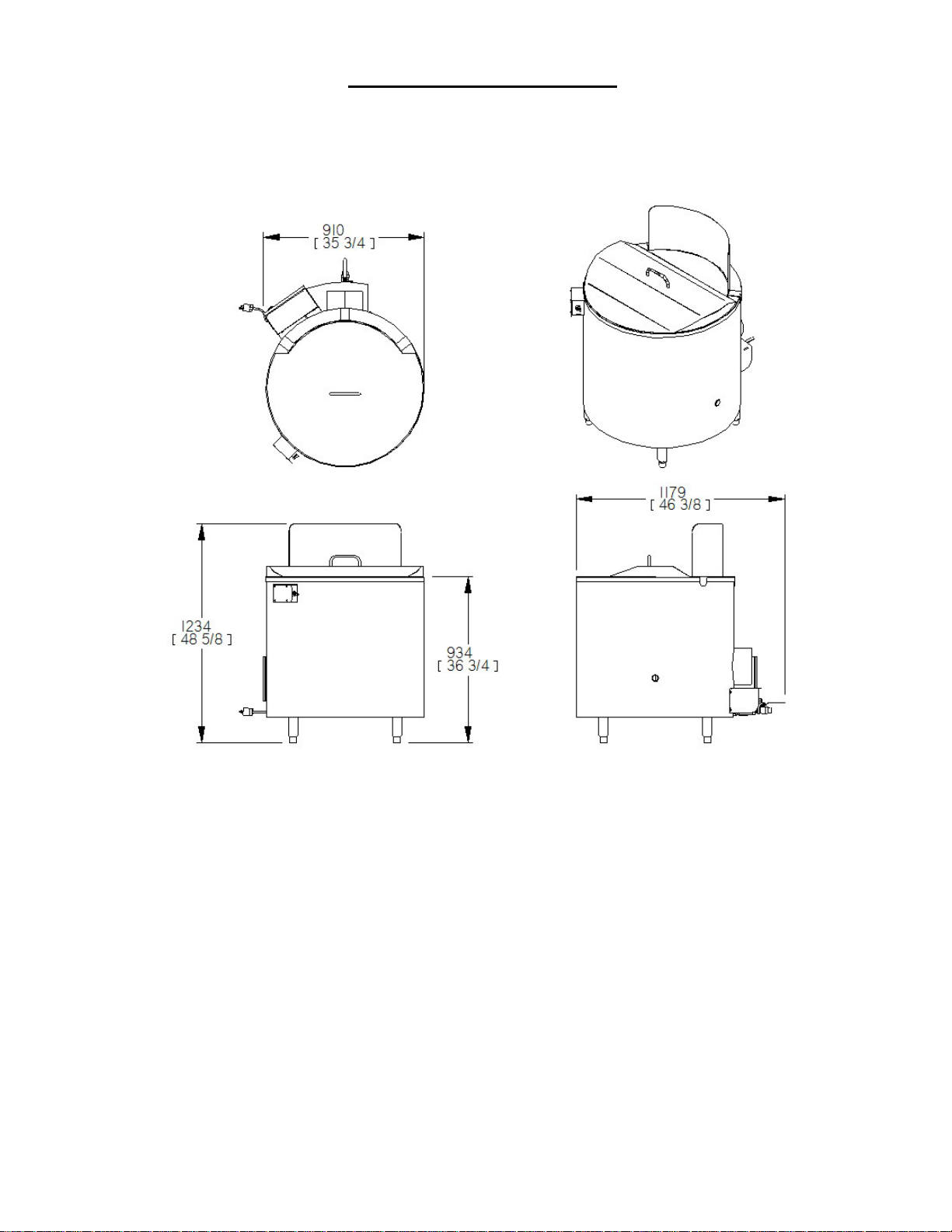
SECTION: INSTALLATION
EXTERNAL DIMENSIONS (BK-45)
17
Page 18
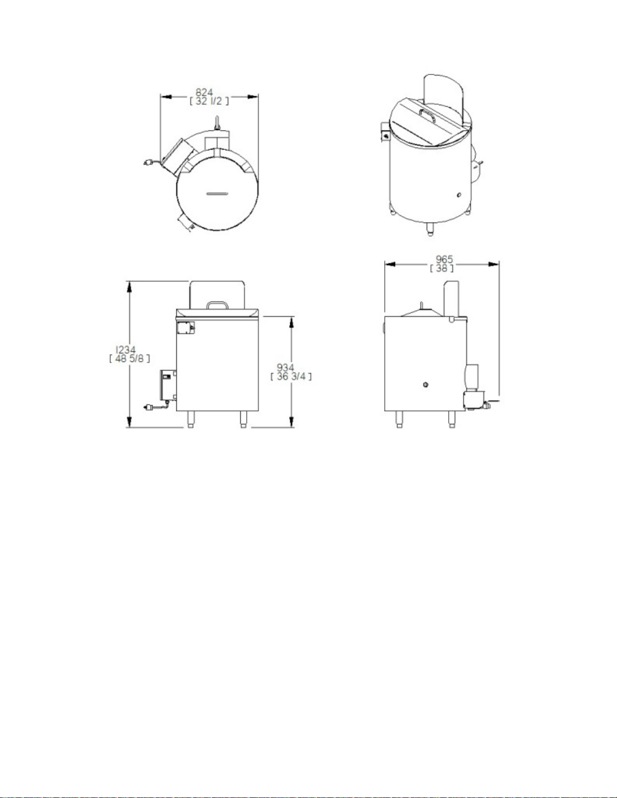
EXTERNAL DIMENSIONS (BK-25)
18
Page 19
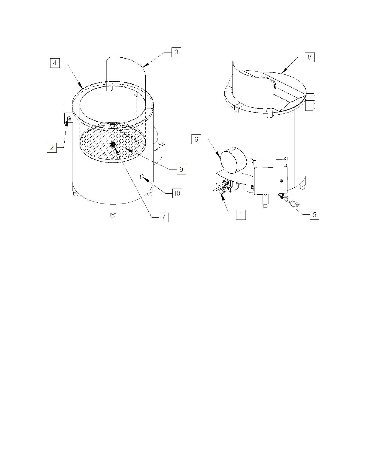
GENERAL COMPONENTS
1. Gas hook- up: ¾ inch NPT.
2. Control button.
3. Splash guard
4. Cauldron
5. Electrical panel
6. Exhaust: 8” OD (203 mm)
7. Drain: 2” NPT (BK-45) 1” NPT (BK-25)
8. Cover
Drain strainer
9.
Flame verification hole
10.
19
Page 20

MINIMAL REQUIRED DISTANCE BETWEEN THE KETTLE AND F LAMMAB L E
COMBUSTIBLE AND NON-COMBUSTIBLE MATERIAL
Kettle side
2 inch of clearance
Kettle back (from flue riser)
24 inches of clearance
Kettle floor
0 inch of clearance non-combustible materiel only
Between units
4 inches or clearance
CAPACITY
LINE
MANIFOLD
4"-6"
COLUMN
LOW – 1.0” W.C.
HI – 3.5” W.C.
12”-14” WATER
COLUMN
LOW – W.C.
HI – W.C.
4"-6"
COLUMN
LOW – 1.0” W.C.
HI – 3.5” W.C.
12”-14” WATER
COLUMN
LOW – W.C.
HI – W.C.
ATTENTION!
NOTE
WARNING!
MATERIAL
GAS CAPACITY AND PRESSURE
MODEL ORIFICE GAS TYPE
BK-25N #65 Natural 62 000
BK-25P Propane
BK-45N #65 Natural 112 000
BK-45P Propane
Picard gas units are manufactured to only be used with the type of gas specified on the rating plates.
The installation must conform to local codes, or in the absence of local codes, to the
ANSI Z223.1 / NFPA 54 (National Fuel Gas Code) CAN/CSA-B149.1 (Natural and or propane gas installation code)
BTU
PRESSURE
WATER
WATER
PRESSURE
IMPROPER INSTALLATION, ADJUSTMENT, ALTERATION, SERVICE OR MAINTENANCE COULD RESULT IN
PROPERTY DAMAGE, INJURY OR EVEN DEATH.
The temperature high limit alarm must always be adjusted to 800° Fahrenheit or 426°Celsius.
20
Page 21
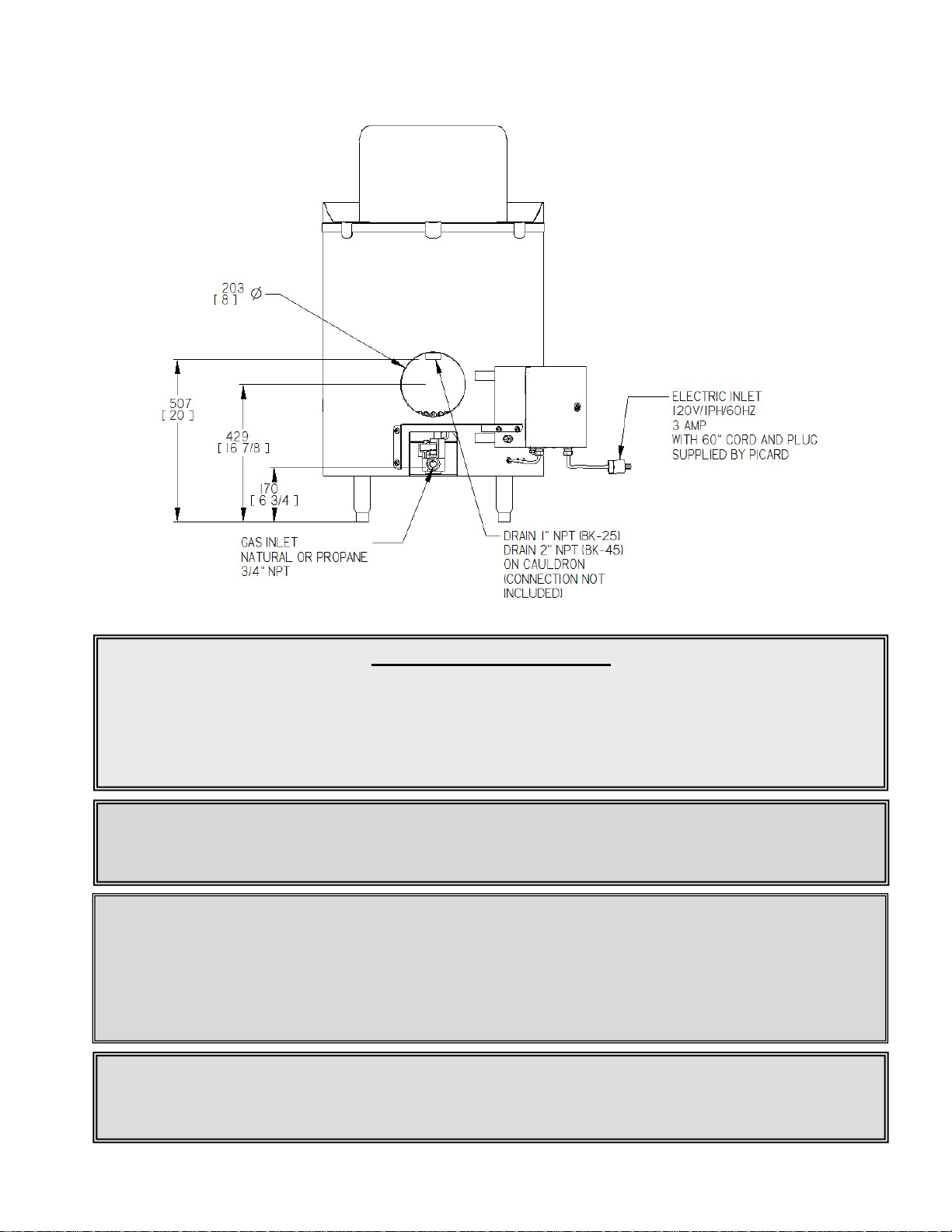
CONNECTIONS LOCATIONS
GAS ENTRY CONNECTION
WARNING
NOTE
IMPORTANT
The kettle must be connected to the gas line by flexible tubing. A gas pressure regulator that complies with ANSI Z21.18 is
required and must be vented properly.
A « quick connect » type connection is recommended (furnished by the client). This will facilitate moving the kettle for
cleaning the walls and floors and it’s long term maintenance.
The diameter of the gas line is dependent on the ducts length; refer to your building codes.
All venting, plumbing and electrical hook ups must be in accordance with federal, state or local code and are the
responsibility and cost of the client.
This kettle must be installed with an adequate anti-air return that conforms to federal, state and local codes.
The gas line of the kettle must be accessible to be turned off manually. In case of emergency or for maintenance, a
manual valve must be close to the equipment and reachable at all time.
21
Page 22
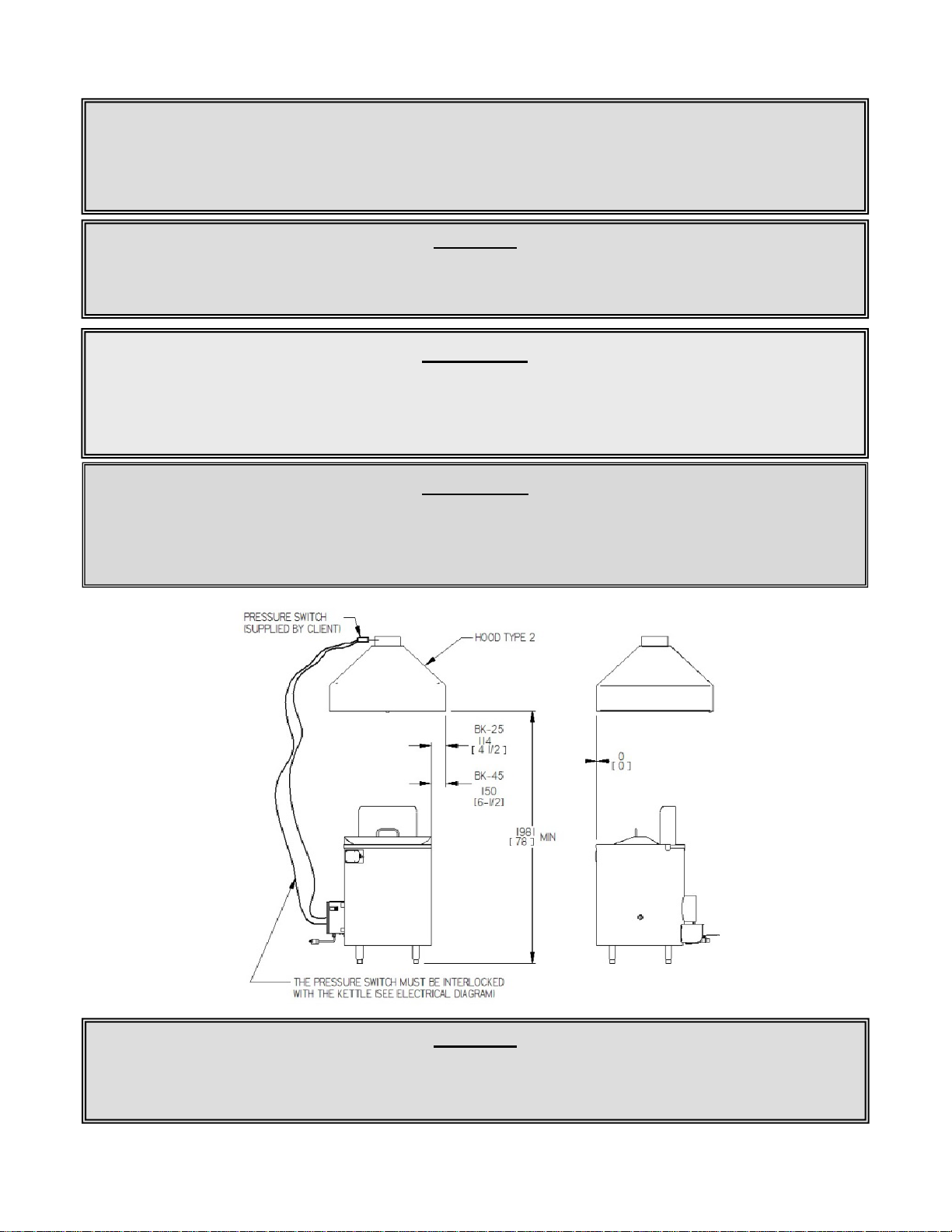
VENTILATION INSTALLATION
IMPORTANT
WARNING
WARNING
ventilation hood must be chosen by a professional as this may vary depending on the distance and the routing between
WARNING
26). A flue riser of 8” in diameter must be attached to the kettle exhaust. The top of the flue
WARNING
Plan ahead a 60’’ (or more) flexible tube for gas inlet (provided by the client) to avoid damages when moving the
All exhaust systems are required to have make-up air system that replaces 100% of the exhaust air. Windows, doors, or
other openings into the establishment cannot be used for the purposes of providing make-up air. A separate duct
providing air into the building is required.
Negative pressure in the room or a faulty exhaust hood installation could damage the electrical components, these type of
damages are not included covered by your warranty.
The Picard kettle must be interlocked with a type 2 venting hood, using a pressure or a vacuum switch (refer to the
electrical diagram on page:
riser must be 2 feet below the hood.
All ventilation connections must in installed to conform to national, provincial or municipal codes in effec t. The type of
the oven and the ventilator and the number of elbows used.
equipment.
22
Page 23

SECTION: RECOMMENDED USAGE
WHAT TO DO IF YOU SMELL GAS?
This appliance does not have a permanent pilot. It has an electronic sparking unit.
Never try to ignite the burner by hand
USAGE INSTRUCTIONS
BEFORE OPERATING, smell for gas odors around the appliance. Be sure to include clo se to the
floor because some gases, like propane, are heavier than air and will settle on the floor.
START UP
1. Connect kettle’s electric plug to a commune plug of 120V/1ph/15A.
2. Fill the cauldron with water
3. Turn the selector button to the “HI” position.
4. Ensure that the burner has been ignited
SHUT DOWN INSTRUCTION
1. Turn the selector button to the “OFF” position
1. Close immediately the manual gas valve.
2. Do not try to turn on any appliances.
3. Do not touch any electrical switch; do not use any phone in your building.
4. Immediately contact your gas supplier us ing a neighbor’s phone. Follow the supplier’s instructions.
5. If you cannot reach your gas supplier, contact the fire depar t ment.
23
Page 24

CONTROL PANEL OPERATION
“OFF” – Turns off the burner
“LOW” – Reduce the burner to low fire rate. Use this mode once the water is boiling.
“HI” – Increase the burner to maximum fire rate.
24
Page 25

SECTION : GENERAL MAINTENANCE
Clean the kettle in general.
Client
Distributor /
Distributor /
Distributor /
IMPORTANT
FICHE D’ENTRETIEN
IT IS VERY IMPORTANT TO DISCONNECT
THE POWER SUPPLY BEFORE SERVICING
AND MAINTENANCE
DAILY
MONTHLY
A
B
Clean the burner pilot *
Change the burner pilot and wire
C
D
Verify and clean the burner *
For repair or maintenance, contact the factory ’s cu sto mer se rv ice department, your sales representative or a local service agency.
www.picardovens.com
*
*
YEARLY
EVERY 6 MONTHS
TO BE MADE OUT
BY:
Certified technician
Certified technician
Certified technician
25
Page 26

CLEANING THE KETTLE:
Important
area. For better security unplug the machine.
• All c leaning of the kettle must be made without hosing or spraying. A s hort damp clothe can be
used with the cleaning product of your choice.
• Avoid liquids from dripping as they can infiltrate into the electrical and mechanical components
causing short and long term problems.
• Avoid the use of scouring pads on stainless steel.
• Avoid water to enter the burner nozzle.
Never light the burner during cleaning. You can damage the kettle or cause bodily injury to people in the
26
Page 27
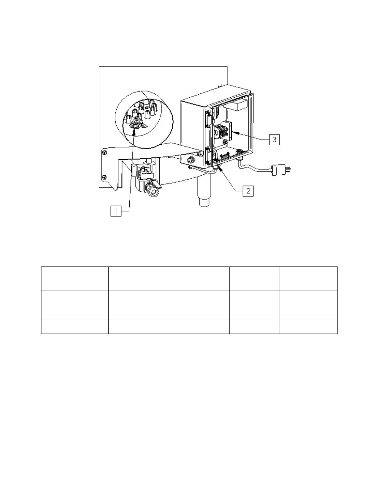
SPARE PARTS
No
Quantity
Description
Part No
Maintenance
1
1
Pilot
PL69-0017
2
1
Ignition wire
EL35-0006
3
1
Fuse 5 amps
EL36-0006
Reference
27
Page 28

TROUBLESHOOTING
Problem
Cause
Solution
The kettle hi limit controller
The kettle has no
-Verify that the kettle is plugged into a power
of the kettle .
The burner isn’t lighting after a
The gas line may be cut.
-Verify that the gas valve on your gas line is in the
12 inches of water column for propane.
The Igniter isn’t
-Verify the fuses, in the el ectric box locat ed on the
-Change the ignition wire.
The burner goes out when it set
The low fire parameters
Communicate with Picard Ovens Customer
won’t turn on after plugging the
main power cord
30 second purge cycle.
to “LOW” position
electricity.
functioning correctly
adjustments are
inadequate.
source.
-Verify the fuses in the electric box on the left side
open position.
-Verify that the gas pressure is between 4 and 6
inches of water column for natural gas and 10 to
left side of the oven.
-Verify that the electrodes are clean.
-Change the igniter.
Service department to schedule a readjustment of
the burner’s parameter s.
28
Page 29

Verification list
Client:
Dealer
Model:
Serial Number:
Circle one
Verify gas pressure is between 4 - 6 W.C for natural gas and 10 –
12 W.C. for propane
Verify the gas manifold pressure: 1.0” W.C. on ”LOW” - 3.5” W.C.
gas)
in the building are in operation.
Person in charge of the kettle
Understands how to use the kettle the right way and safely
Understands maintenance
Customer's name (print): Signature:
Installer's name ( print): Signature:
Installation date:
Gas connections already installed on site Yes No
Ventilation Hood Installed Yes No
Verify all buttons of control panel Yes No
Do you have a pressure Indicator (U tube) Yes No
Yes No
Note the gas line pressure:
on “HI” (Natural gas) / ” W.C. on “LOW” – ” W.C. on “HI” (Propane
Yes No
Note the gas manifold pressure
Verify that the burner works Yes No
Verify that there isn't negative pressure while all venting systems
Yes No
Yes No
Yes No
Understand who to contact for service. Yes No
Notes:
29
Page 30
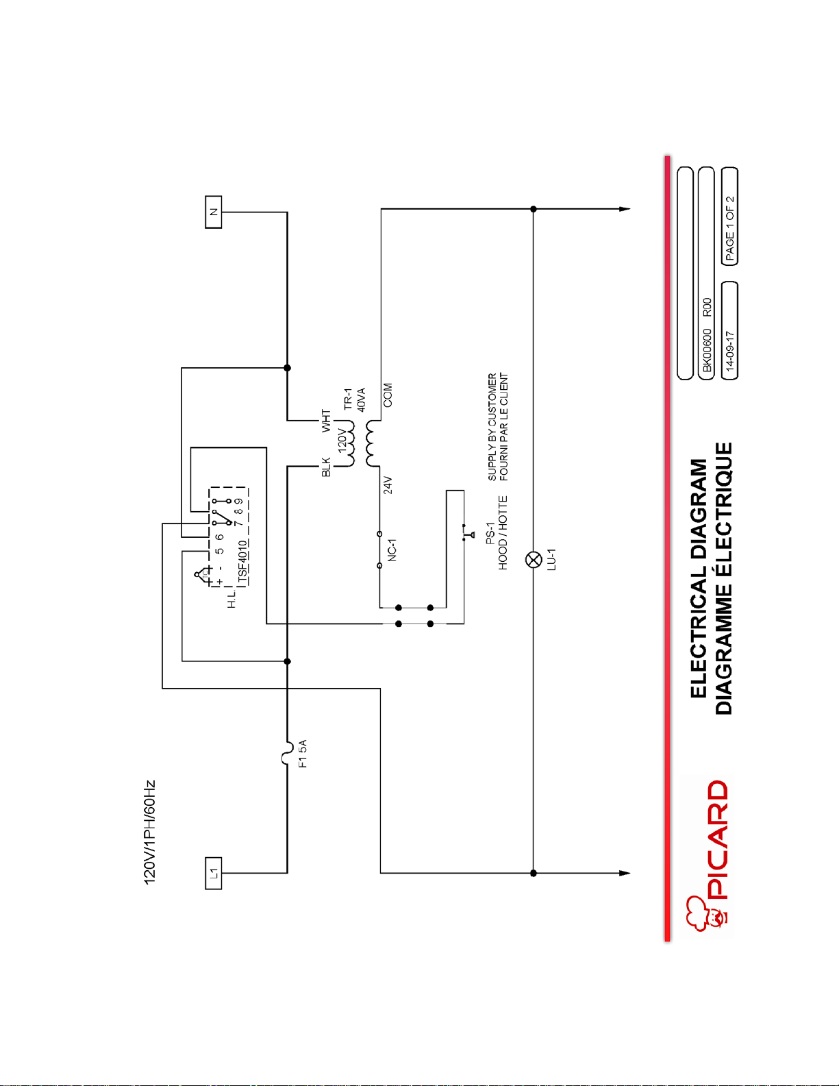
ELECTRIC PLANS
30
Page 31
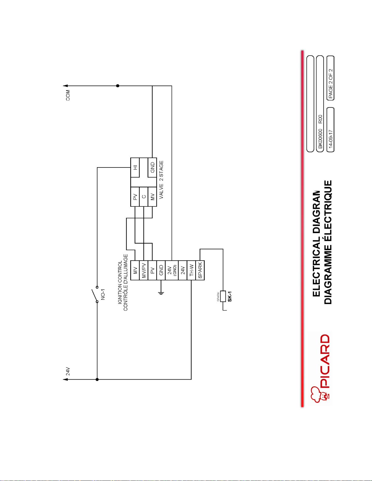
31
Page 32

Client Responsibilities:
Precisions and limitations of liability
USA & Canada Sales Conditions and Limited Warranty
Picard Ovens, inc. warrants its equipment to be free from defect in material and factory workmanship under normal use
for (1) one year from the date of the original Installation at the end client location to the original client. All warranty
service must be pre-approved by Picard Ovens and have service authorization number prior to the execution of any
services. Please contact our service department at 1 819-395-5151 or toll free at 1 855-395-5252. Our business hours
are 8 a.m. to 5 p.m. Monday through Friday, Eastern time zone. If calling during non business hours, follow the recorded
instructions for emergency service and someone will promptly contact you.
All necessary utilities must be installed to code by a licensed contractor and ready at start up. The client must inspect
the equipment and crates at their delivery. Damage during transportation must be reported directly to the transportation
company and to Picard Ovens. When installation of Picard equipment is made by an authorized dealer or any other
person than one of Picard’ employees, even in the presence of a Picard supervisor, the dealer or person installing shall
be the only person responsible of any faulty installation of the equipment, no warranty being given by Picard on an
installation performed by any person other than one of Picard’s own employees. No labor warranty applies in such
cases.
All Installations must be made by authorized service technicians and in accordance to the instructions furnished with the
unit. The client must supply proof of the installation and the initial startup by filling out the forms furnished at the back of
the owners users guide, dually signed by both the client and the service technician as witness that all required steps and
verifications were successfully carried out and the installation is acceptable to the client. The form may be faxed or
mailed to Picard Ovens at the coordinates found at the bottom of the page.
Proper maintenance procedures are found in the operators guide.
This warranty is conditioned upon the following terms:
• The successful registration of the installation and start up forms.
• Terms of payment have been met.
• The equipment has not been accidentally or intentionally damaged, altered, misused or abused.
• Warranty coverage is at the sole discretion and is the exclusive right of Picard Ovens.
• Warranty replacement parts will be sent out under the authority of Picard Ovens, prepaid freight, expedited
in the most rapid manner possible. It is the responsibility of the client to return all defective parts to the
factory prepaid for proper warranty credit to be reimbursed.
In the event of warranty claim or otherwise, the sole obligation of Picard Ovens shall be to repair and / or to replace
equipment or equipment components, at their own discretion. Such repair or replacement shall be at the expense of
Picard Ovens with the exception of travel over 100 miles or two hours, overtime and holiday charges which shall be at
the clients expense. Any repairs or replacement of equipment or its parts, under this warranty does not constitute an
extension of the original warranty for any period. Parts to be replaced under this warranty will be repaired or replaced
with new or functionally operative parts at the option of Picard Ovens.
Picard Ovens liability on any claim of any kind, including claims based on warranty, expressed or implied, contract,
negligence, strict liability or any other theories shall be solely and exclusively the repair or replacement of the product as
stated herein, and such liability shall not include, and purchaser specifically renounces any rights to recover, special,
incidental, consequential or other damages of any kind whatsoever, including, but not limited to, injuries to persons or
damage to property, loss of profits or anticipated profits, or loss of use of the product.
:
Damages are limited to the original purchase price.
32
Page 33

Warranty labor charges will be calculated and paid using reasonable normal business hours and rates. This is to say
Exclusions:
Handling claims:
Picard will pay 8 hours labor at a regular (Monday through Friday 8a.m. to 5 p.m.) hourly rate and within a 100 miles
distance. Any overtime or excess travel charges will be the client’s responsibility.
Any damage incurred during transportation.
Use of any high pressure cleaning equipment will void this warranty.
Normal cleaning and maintenance functions: including lubrication or greasing.
Parts that would normally wear or need replacement under normal use (example: light bulbs, fuses, thermo-couples,
belts and filters).
In the event that:
• There is failure or malfunction of the equipment or any of its components caused by abnormal or
improper use or the failure is otherwise not attributable to a material or manufacture defect.
• Any failure caused by improper use, including but not limited to improper shelf loading.
• The equipment has been altered from its original factory condition.
• The rating plate has been removed, altered or obliterated.
• The equipment has been improperly maintained, proper maintenance is the responsibility of the client.
• Any parts that become defective because of utility services (power surges, high or low voltages, high
or low gas pressure of volume, contaminated fuel or improper utility connections).
This warranty shall not apply if the equipment or any part is damaged as a result of accident, casualty, alteration,
misuse, abuse, improper cleaning, improper installation, improper operation (including improper tray loading resulting in
shelf jams, natural or manmade disasters). In no event shall Picard Ovens be held liable for direct, incidental or
consequential damages arising out of or resulting from the operation of this equipment.
Picard assumes no liability for any contingent or consequential damages incurred by the client, including but not limited
to down time, loss of business, damage or product loss.
In the event that the client denies access to an authorized technician (whom has been scheduled to make a service call)
upon their arrival, releases Picard Ovens from of any and all warranted obligations and all expenses incurred are the
sole responsibility of the client.
Note: Oven facades, windows, light bulbs, granite or baking stones are not covered under this warranty.
In case of any litigation or claim whatsoever regarding this Limited Warranty, the only competent courts shall be the
ones of the judicial district of Drummond, province of Quebec, Canada. This Limited Warranty and all sales agreements
for the equipment shall be construed, interpreted and executed in accordance with the laws in force in the province of
Quebec, Canada.
As soon as a defect is discovered, Picard Ovens must be notified. Our service manager will arrange for an authorized
service agent to make the necessary repairs.
Call or email:
33
Page 34

A
P
P
E
N
D
I
X
34
Page 35
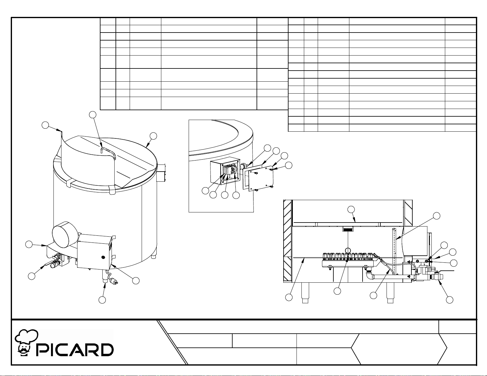
No. Qté No de pièce Description Matériel
15 1 EL35-0006 Fil d'allumage 36"
16 1 BK45015 Assemblage soudé couvercle
17 1 BK45115 Pare feu S.S. 304 2B
18 1 BK45016 Grille du drain du chaudron
19 4 ME41-0067 Patte ajustable 3/4-10 - 6" - acier
inoxydable
20 4 QU28-0022 Vis machine ronde étoile 10-24 x 1/2
acier inoxydable
21 4 QU28-0093 Vis tête goutte de suif 1/4-20 x 1/2 18.8 ss
22 4 QU28-0054 Rondelles plates 1/4 ss S.S.
23 4 QU28-0030 Boulon 1/4 x 3/4 NC autotaraudeuse type f
hexagone avec épaulement
S.S.
S.S.
16
13
No. Qté No de pièce Description Matériel
1 1 BK45008 Soudure du bidon
2 1 BK45005 Assemblage du brûleur
3 1 BK45012 Soudure du chaudron
4 1 BK00130 Cache proble hi limit S.S. 304 2B
5 1 BK00109 Couvercle du boité de contrôle S.S. 304-4
6 1 EL01-0003 Bloc contact N.O pour bouton
7 1 FO79-0010 Bande autocollante 1/2" x 1/8" épais NEOPRÈNE
8 1 EL01-0005 Bloc contacteur N.C pour bouton
9 1 EL37-0049 Lumière 24v ac pour bouton vert
10 1 EL01-0001 Support en plastique pour bouton
11 1 EL01-0048 Sélecteur 3 positions lumineux
12 1 BK45129 Garde valve S.S. 304-4
13 1 BK45014 Soudure du pare éclaboussure
14 1 BK00006 Assemblage du boitié électrique
3
11
7
5
20
6
9
8
10
12
2
19
LES FOURS PICARD INC. / PICARDS OVENS INC.
14
TITRE:
240, blvd Industriel
St-Germain de Grantham
(Qc) J0C 1K0
Tél: (819) 395-5151
Fax: (819) 395-5343
Internet: www.picardsoven.com
ÉCHELLE
1:15
NO° D'ASSEMBLAGE:
(SCALE)
1:8
PROJET
17
Bouilloir 45 gallons
(PROJECT)
S-0001
(ASSEMBLY NO°)
TOLÉRANCES:
(TOLERANCES)
DATE:
(AA/MM/JJ)
FRAC. /32"
x.x ±0.01"
(YY/MM/DD)
14-08-19
23
1:12
X.XX±0.005"
X.XXX ±0.001"
18
4
22
12
21
15
N° DESSIN:
(DRAWING N°)
BK45002
(TITLE)
2
QUANTITÉ:
(QUANTITY)
RÉVISIONS:
(REVISION)
1
0
Page 36
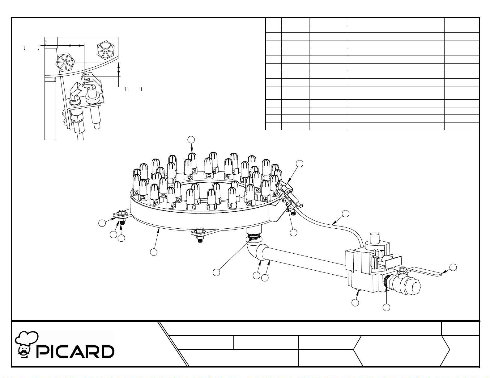
21.62
.851"
15.96
.628"
No. Quantité No de pièce DESCRIPTION Matériel
1 1 BK45011 Assemblage soudé du brûleur
2 1 PL69-0017 Étincelle d'allumage intermittent
3 1 PL07-0024 Valve à gaz 2 stages 24V
4 1 PL07-0011 Valve à bille 3/4 IPS NCI (gaz)
5 1 BK45300 Tuyau d'admission de gaz du brûleur ACIER
6 1 PL29-0025 Coude noir 3/4 x 90 ACIER
7 1 Tube d'admission de gaz du pilote (None)
8 2 PL29-0209 Mamelon noir 3/4 x 1 1/2(cl) ACIER
9 2 QU28-0084 Vis machine ronde carré 10-32 x 1/4
plaqué
10 4 QU28-0009 Écrou 3/8-16 hex nc plaqué gr2 ACIER
11 4 QU28-0059 Boulons 3/8 x 1 hex gr5 plaque ACIER
12 8 QU28-0078 Rondelles plates 3/8 plaque ACIER
13 36 PL70-0012 Buse #65 1/8"NPT
Steel
13
1:2
12
LES FOURS PICARD INC. / PICARDS OVENS INC.
10
11
1
240, blvd Industriel
St-Germain de Grantham
(Qc) J0C 1K0
Tél: (819) 395-5151
Fax: (819) 395-5343
Internet: www.picardsoven.com
TITRE:
ÉCHELLE
1:4
NO° D'ASSEMBLAGE:
BK45002
2
7
9
4
8
(SCALE)
PROJET
6
5
Assemblage du brûleur
(PROJECT)
S-0001
(ASSEMBLY NO°)
TOLÉRANCES:
(TOLERANCES)
DATE:
(AA/MM/JJ)
FRAC. /32"
X.XX±0.005"
x.x ±0.01"
X.XXX ±0.001"
(YY/MM/DD)
14-08-14
3
8
N° DESSIN:
(DRAWING N°)
BK45005
(TITLE)
QUANTITÉ:
(QUANTITY)
RÉVISIONS:
(REVISION)
1
0
Page 37
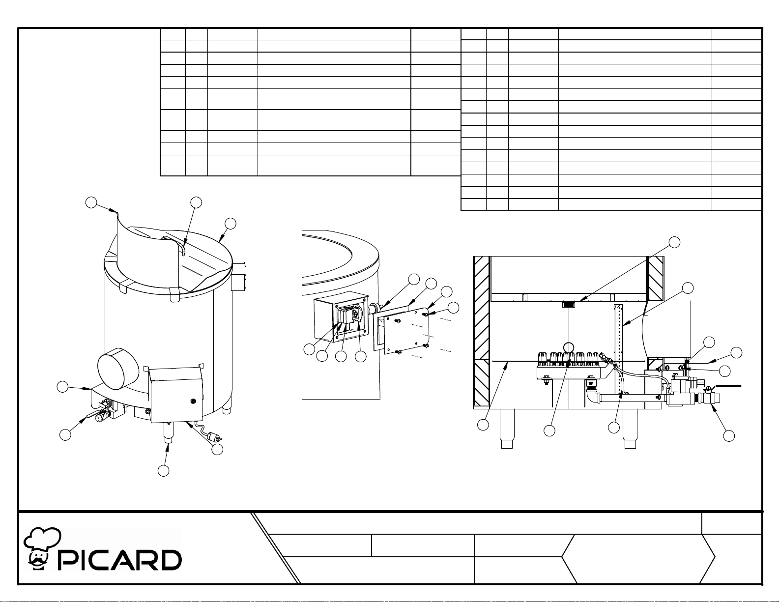
No. Qté No de pièce Description Matériel
15 1 EL35-0006 Fil d'allumage 36"
16 1 BK25015 Assemblage soudé couvercle
17 1 BK25115 Pare feu S.S. 304 2B
18 1 BK25016 Grille du drain du chaudron
19 4 ME41-0067 Patte ajustable 3/4-10 - 6" - acier
20 4 QU28-0022 Vis machine ronde étoile 10-24 x 1/2
21 4 QU28-0093 Vis tête goutte de suif 1/4-20 x 1/2 18.8 ss
22 4 QU28-0054 Rondelles plates 1/4 ss S.S.
23 4 QU28-0030 Boulon 1/4 x 3/4 NC autotaraudeuse type f
13
16
hexagone avec épaulement
inoxydable
acier inoxydable
S.S.
S.S.
No. Qté No de pièce Description Matériel
1 1 BK25008 Soudure du bidon
2 1 BK25005 Assemblage du brûleur
3 1 BK25012 Soudure du chaudron
4 1 BK00130 Cache proble hi limit S.S. 304 2B
5 1 BK00109 Couvercle du boité de contrôle S.S. 304-4
6 1 EL01-0003 Bloc contact N.O pour bouton
7 1 FO79-0010 Bande autocollante 1/2" x 1/8" épais NEOPRÈNE
8 1 EL01-0005 Bloc contacteur N.C pour bouton
9 1 EL37-0049 Lumière 24v ac pour bouton vert
10 1 EL01-0001 Support en plastique pour bouton
11 1 EL01-0048 Sélecteur 3 positions lumineux
12 1 BK25129 Garde valve S.S. 304-4
13 1 BK25014 Soudure du pare éclaboussure
14 1 BK00006 Assemblage du boitié électrique
3
3
11
7
5
4
20
12
2
19
LES FOURS PICARD INC. / PICARDS OVENS INC.
14
TITRE:
240, blvd Industriel
St-Germain de Grantham
(Qc) J0C 1K0
Tél: (819) 395-5151
Fax: (819) 395-5343
Internet: www.picardsoven.com
6
9
ÉCHELLE
1:15
NO° D'ASSEMBLAGE:
22
8
10
12
21
(SCALE)
1:7
PROJET
17
Bouilloir 25 gallons
(PROJECT)
S-0001
(ASSEMBLY NO°)
TOLÉRANCES:
(TOLERANCES)
DATE:
(AA/MM/JJ)
FRAC. /32"
x.x ±0.01"
(YY/MM/DD)
14-08-19
23
X.XX±0.005"
X.XXX ±0.001"
15
N° DESSIN:
(DRAWING N°)
BK25002
(TITLE)
2
QUANTITÉ:
(QUANTITY)
RÉVISIONS:
(REVISION)
1
0
Page 38
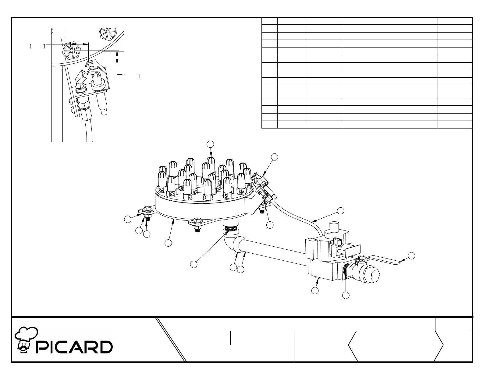
20.66
.813"
15.81
.622"
No. Quantité No de pièce DESCRIPTION Matériel
1 1 BK25011 Assemblage soudé du brûleur
2 1 PL69-0017 Étincelle d'allumage intermittent
3 1 PL07-0024 Valve à gaz 2 stages 24V
4 1 PL07-0011 Valve à bille 3/4 IPS NCI (gaz)
5 1 BK25300 Tuyau d'admission de gaz du brûleur ACIER
6 1 PL29-0025 Coude noir 3/4 x 90 ACIER
7 1 Tube d'admission de gaz du pilote (None)
8 2 PL29-0209 Mamelon noir 3/4 x 1 1/2(cl) ACIER
9 2 QU28-0084 Vis machine ronde carré 10-32 x 1/4
plaqué
10 4 QU28-0009 Écrou 3/8-16 hex nc plaqué gr2 ACIER
11 4 QU28-0059 Boulons 3/8 x 1 hex gr5 plaque ACIER
12 8 QU28-0078 Rondelles plates 3/8 plaque ACIER
13 20 PL70-0012 Buse #65 1/8"NPT
Steel
13
1:2
LES FOURS PICARD INC. / PICARDS OVENS INC.
12
10
11
TITRE:
240, blvd Industriel
St-Germain de Grantham
(Qc) J0C 1K0
Tél: (819) 395-5151
Fax: (819) 395-5343
Internet: www.picardsoven.com
1
8
ÉCHELLE
NO° D'ASSEMBLAGE:
BK25002
1:4
(SCALE)
2
9
6
5
3
Assemblage du brûleur
PROJET
S-0001
(PROJECT)
(ASSEMBLY NO°)
TOLÉRANCES:
(TOLERANCES)
DATE:
(AA/MM/JJ)
FRAC. /32"
x.x ±0.01"
14-08-14
7
X.XX±0.005"
X.XXX ±0.001"
(YY/MM/DD)
4
8
(TITLE)
QUANTITÉ:
N° DESSIN:
(DRAWING N°)
BK25005
(QUANTITY)
1
RÉVISIONS:
(REVISION)
0
Page 39
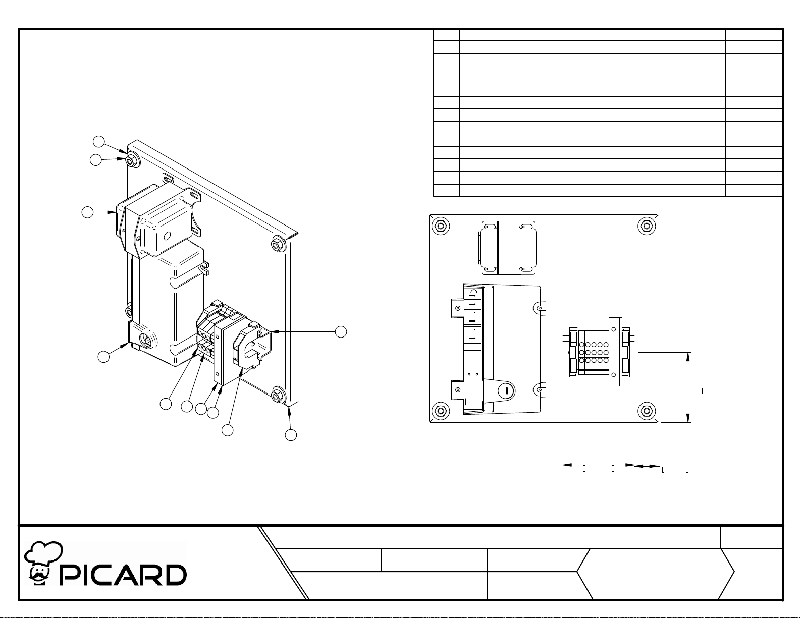
No. Quantité No de pièce DESCRIPTION Matériel
1 1 BK00113 Plaque de fond du boitié électrique S.S. 304 2B
2 1 EL02-0008 Contrôle d'allumage électronique (special
3 1 EL40-0006 Transformateur 40VA 120/208/240V -
4 1 EL36-0012 Porte fusible sur rail
5 1 EL05-0105 Plaquette d'extrémité pour porte fusible
6 1 EL05-0036 Rail/2m barre de 2 mètre GALVANISÉ
9
10
7 1 EL05-0081 Pièce d'embout pour bornier
8 2 EL05-0002 Butées d'arret pour bornier
9 4 QU28-0054 Rondelles plates 1/4 ss S.S.
10 4 QU28-0155 Écrou 1/4 nc ss S.S.
11 5 EL05-0001 Bornier 600V/32A
60/50hz)
24VAC
3
2
7
LES FOURS PICARD INC. / PICARDS OVENS INC.
11
4
5
8
240, blvd Industriel
St-Germain de Grantham
(Qc) J0C 1K0
Tél: (819) 395-5151
Fax: (819) 395-5343
Internet: www.picardsoven.com
TITRE:
6
1
75mm
2.953"
NOTES: FIXER AVEC VIS TEK
Assemblage plaque de fond du boité électrique
ÉCHELLE
1:3
NO° D'ASSEMBLAGE:
BK00006
(SCALE)
PROJET
S-0001
(PROJECT)
(ASSEMBLY NO°)
TOLÉRANCES:
(TOLERANCES)
DATE:
(AA/MM/JJ)
FRAC. /32"
x.x ±0.01"
14-08-18
X.XX±0.005"
X.XXX ±0.001"
(
YY/MM/DD)
73.4mm
2.890"
25mm
.984"
N° DESSIN:
(DRAWING N°)
BK00007
(TITLE)
QUANTITÉ:
(QUANTITY)
RÉVISIONS:
(REVISION)
1
0
Page 40
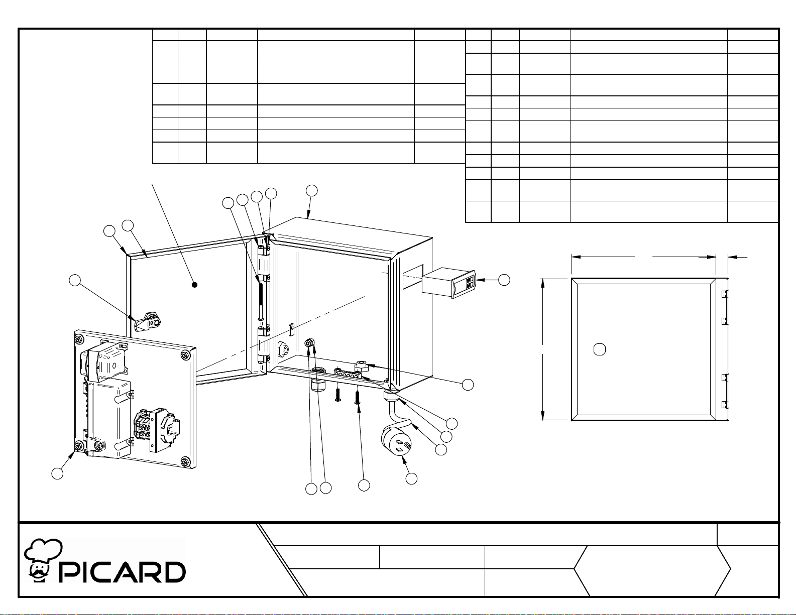
COLLER UN PLAN
ÉLECTRIQUE MINIATURE
DANS LA PORTE
6
4
No. Qté No de pièce DESCRIPTION Matériel
12 2 QU82-0015-1Penture caché acier inoxydable 304 - male
13 2 QU28-0486 Vis tête ronde 10-24 x 2-1/2" phillips acier
14 2 QU28-0446 Vis machine ronde étoile 10-24 x 3/4 acier
15 4 QU28-0007 Écrou 5/16 hex nc ss S.S.
16 4 QU28-0155 Écrou 1/4 nc ss S.S.
17 4 QU28-0055 Écrou hexagone 10-24 nc acier inoxydable S.S.
18 4 QU28-0021 Vis tête fraisé 10-24 x 1/2 phillips m/s 18.8
12
18
17
13
inox.
inoxydable
ss
1
S.S.
S.S.
No. Qté No de pièce DESCRIPTION Matériel
1 1 BK00010 Soudure du boitié électrique
2 1 BK00007 Assemblage plaque de fond du boité
3 1 EL02-0104 Contrôle de température maximale120V
4 1 BK00013 Soudure porte du boité électrique
5 1 QU59-0058 Serrure quart de tour
6 1 FO79-0019 Bande autocollante en "D" EPDM 3/8" x
7 1 EL80-0044 Barette de mise à la terre 6 trous ALUMINIUM
8 6' Fil SWJOO 14/3
9 1 EL05-0052 Fiche mâle 15a 125v jaune
10 2 EL65-0050 Presse étoupe cd13 + o-ring + écrous (1/2"
11 2 EL65-0049 Presse étoupe cd09 + o-ring + écrous (3/8"
électrique
Fahrenheit
1/4"
npt)
npt)
PLASTIQUE
PLASTIQUE
5
2
LES FOURS PICARD INC. / PICARDS OVENS INC.
TITRE:
240, blvd Industriel
St-Germain de Grantham
(Qc) J0C 1K0
Tél: (819) 395-5151
Fax: (819) 395-5343
Internet: www.picardsoven.com
15
16
ÉCHELLE
1:5
NO° D'ASSEMBLAGE:
BKXX002
3
248.5
11
7
10
8
14
9
NOTES:
1- INSTALLER LE BOITIÉ SUR LA MACHINE
2- INSÉRER LE PANNEAU ÉLECTRIQUE
3- INSTALLER LE CONTROLLEUR DE TEMPÉRATURE
Assemblage du boitié électrique
(SCALE)
PROJET
S-0001
(PROJECT)
(ASSEMBLY NO°)
TOLÉRANCES:
(TOLERANCES)
DATE:
(AA/MM/JJ)
FRAC. /32"
x.x ±0.01"
14-08-18
X.XX±0.005"
X.XXX ±0.001"
(YY/MM/DD)
253
N° DESSIN:
(DRAWING N°)
BK00006
(TITLE)
QUANTITÉ:
(QUANTITY)
RÉVISIONS:
(REVISION)
21.6
1
0
 Loading...