

Page 1

Piaggio would like to thank you
for choosing one of its products. We have drawn up this booklet to show you all features of our product. Please read the booklet carefully before using
your vehicle. It includes information, suggestions and warnings regarding your vehicle. You will also be informed of features, details and devices that
will prove the excellence of your choice. We believe that if you follow our suggestions you will soon tune in with your vehicle and use it for a long time
at full satisfaction.
This booklet is an integral part of the vehicle, and upon sale, it should be transferred to the new owner.
Ape TM - Ape TM Diesel
Ed. 01_02/2012
Page 2

INSTRUCTIONS
The instructions given in this booklet are intended to provide a clear, simple guide to using your scooter; details are also given of routine maintenance
procedures and regular checks that should be carried out on the vehicle at an Authorised PIAGGIO Dealer or Service Centre. The booklet also
contains instructions for simple repairs. Any operations not specifically described in this booklet require the use of special tools and/or particular technical
knowledge: to carry out these operations refer to any authorised PIAGGIO Dealer of Service Centre. Read this booklet carefully before using your
vehicle. Follow the instructions contained in this booklet for your personal safety and to ensure long-lasting use of your vehicle. Failure to observe these
instructions may cause personal injury or damage to the vehicle.
2
Page 3
Personal safety
Failure to completely observe these instructions will result in serious risk of personal
Safeguarding the environment
Sections marked with this symbol indicate the correct use of the vehicle to prevent dam-
aging the environment.
The incomplete or non-observance of these regulations leads to the risk of serious
damage to the vehicle and sometimes even the invalidity of the guarantee.
The signs indicated on this page are very important, they highlight the parts of the booklet
that should be read with particular care. Each sign consists of a different graphic symbol,
making it quick and easy to locate the various topics.
injury.
Vehicle intactness
3
Page 4

4
Page 5

INDEX
IDENTIFICATION......................................................................... 7
Vehicle identification number.................................................... 8
SAFE RIDING.............................................................................. 11
Safe drive.................................................................................. 12
Running-in period...................................................................... 12
VEHICLE USE.............................................................................. 13
Checks...................................................................................... 14
Before starting the engine......................................................... 18
Engine start up.......................................................................... 19
Stopping the engine.................................................................. 21
Starting difficulties..................................................................... 21
Gear position............................................................................. 22
Driving Tips............................................................................... 23
DOORS AND LOCKS.................................................................. 27
Keys.......................................................................................... 28
Door locking/unlocking by key............................................... 28
Front door windows................................................................... 29
Engine inspection port.............................................................. 30
SEATS AND SAFETY BELTS..................................................... 31
Using the safety belts................................................................ 32
Fasting the safety belt........................................................... 33
Adjusting the safety belt........................................................ 34
To release the safety belt...................................................... 34
INSTRUMENT PANEL AND CONTROLS................................... 35
Handlebars............................................................................ 36
Steering wheel....................................................................... 39
Controls..................................................................................... 43
Ignition switch........................................................................... 53
GAUGES AND WARNING LIGHTS............................................ 55
Instrument unit and indicators................................................... 56
AIR CONTROL SYSTEM............................................................. 57
Heating.................................................................................. 58
Heating and demisting........................................................... 59
Demisting.............................................................................. 59
MIRRORS AND WINDOW GLASSES......................................... 61
Adjusting the mirror............................................................... 62
Wipers and Brushes.................................................................. 62
INSIDE EQUIPMENT................................................................... 65
ELECTRICAL SYSTEM............................................................... 67
Fuel version.............................................................................. 68
Diesel version........................................................................... 68
EMERGENCY.............................................................................. 71
Wheel replacement................................................................... 72
Maintenance instructions....................................................... 72
MAINTENANCE........................................................................... 75
Check engine oil level........................................................... 76
Oil change and oil filter replacement..................................... 76
Checking the brake fluid level................................................... 79
Gear box oil level...................................................................... 81
Window washer fluid level......................................................... 83
Cooled fluid............................................................................... 83
Changing the engine cooling fluid......................................... 84
Checking and replacing the air cleaner element....................... 84
Replacing the fuel filter............................................................. 85
Air bleeding........................................................................... 86
Fuel exhaustion..................................................................... 86
Checking and replacing the pre-heating plugs.......................... 87
Fuses........................................................................................ 88
Exhaust circulation system (EGR)......................................... 91
Tyres......................................................................................... 91
Pressure................................................................................ 92
Periods of inactivity................................................................... 92
Troubleshooting / What to do if................................................. 98
SPARE PARTS AND ACCESSORIES........................................ 107
Warnings................................................................................... 108
TIPPER VERSION....................................................................... 109
5
Page 6

System Operation..................................................................... 110
Warnings for Loading and Unloading Operations..................... 111
Scheduled Maintenance........................................................... 114
Extraordinary Maintenance....................................................... 116
Trouble-Shooting...................................................................... 117
Warning Plate Symbols............................................................. 120
technical sheet for EC conformity declaration........................... 123
Preface.................................................................................. 123
Equipment Layout................................................................. 124
Analysis of Risks Connected with the Layout and Operation
of the Equipment................................................................... 127
TECHNICAL DATA...................................................................... 135
Vehicle...................................................................................... 138
SCHEDULED MAINTENANCE - CHECKS................................. 149
Scheduled maintenance service............................................... 150
6
Page 7

Ape TM - Ape TM Diesel
Chap. 01
Identification
7
Page 8
01_01
01_02
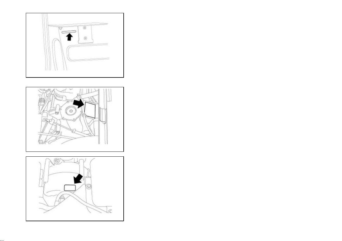
Vehicle identification number (01_01, 01_02, 01_03)
The identification codes consist of a prefix followed by a number punched on the
chassis and on the engine, respectively.
Always quote the serial numbers when ordering spare parts.
The chassis identification number is located on the crossmember under the seat as
shown in the figure.
The frame identification code is:
ZAPT1000000001001
Check that the chassis prefix and number punched on the vehicle correspond to that
shown on the vehicle documents.
The engine identification number is printed as shown in the figure.
The first indicates the location of the plate on the diesel engine, while the second is
on the gasoline engine.
The gasoline version engine identification initials are:
ATM2M
The diesel version engine identification initials are:
LDW 422
01_03
8
Page 9
1 Identification
CAUTION
BE REMINDED THAT ALTERING IDENTIFICATION REGISTRATION NUMBERS
MAY LEAD TO SERIOUS PENAL SANCTIONS (IMPOUNDING OF THE VEHICLE.
ETC.)
9
Page 10

10
Page 11
Ape TM - Ape TM Diesel
Chap. 02
Safe riding
11
Page 12
02_01
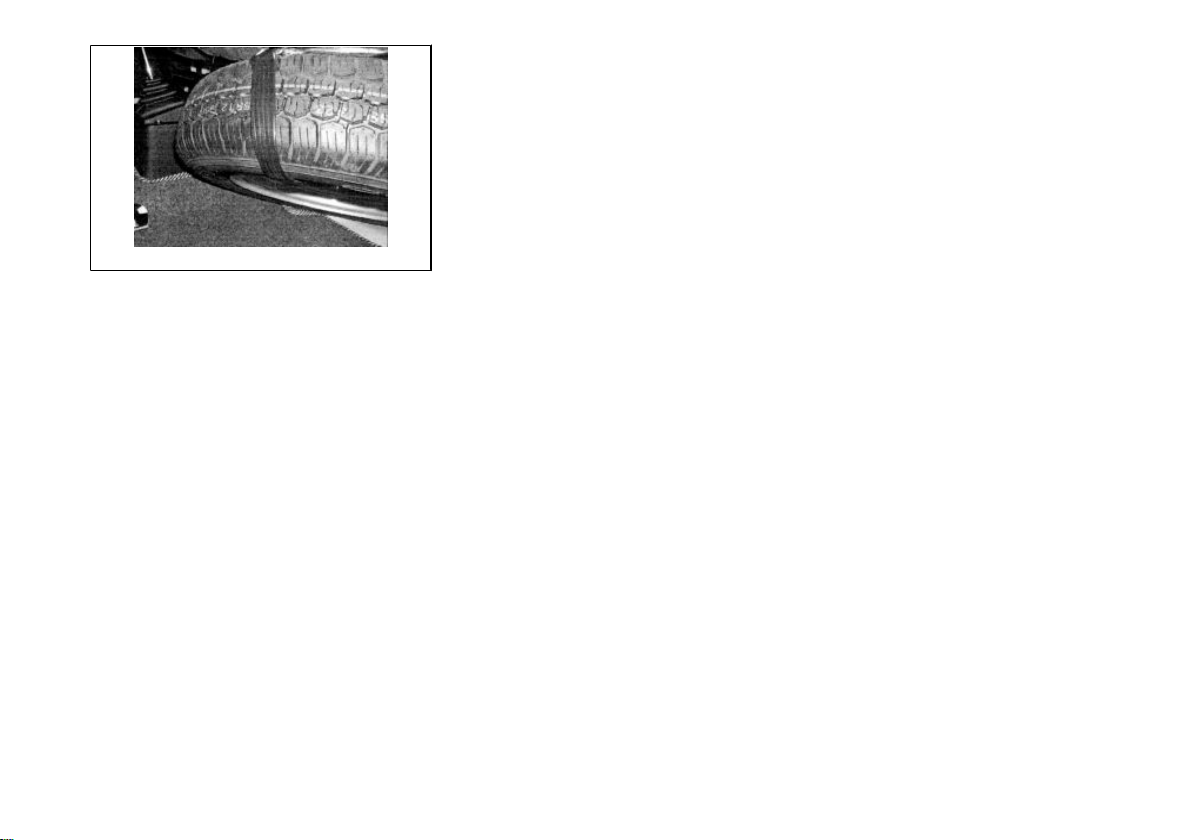
Safe drive (02_01)
ENSURE THE SPARE WHEEL IS CORRECTLY SECURED TO THE SEAT
THROUGH THE RETAINING STRAP, IN ORDER TO PREVENT IT FROM MOVING
IN THE EVENT OF AN EMERGENCY STOP.
Running-in period
During the first 1000 km, do not twist the throttle fully open and avoid driving at constant
speed over long stretches of roads. After the first 1000 km gradually increase speed
until reaching the maximum performance.
12
Page 13

Ape TM - Ape TM Diesel
Chap. 03
Vehicle use
13
Page 14
TYRE PRESSURE
Front tyre pressure 2.5 atm
Rear tyre pressure 4.5 atm
Checks (03_01, 03_02, 03_03, 03_04)
Before using the vehicle, check:
1. That the oil and fuel (for fuel versions) tanks are filled.
2. The engine/transmission oil level (for diesel versions).
3. The brake fluid level.
4. That the tyre inflation pressure is correct.
5. Correct operation of side/taillights, headlights and turn indicators.
6. Front and rear brake operation.
7. Gearbox oil level (for petrol versions).
8. Electrolyte and battery charge check.
9. Check coolant (diesel version)
CAUTION
TYRE PRESSURE SHOULD BE CHECKED WHEN TYRES ARE COLD.
Fuel tank
14
Page 15
3 Vehicle use
The fuel filler cap is fitted with a lock.
To open: insert the supplied key and turn it anticlockwise.
To close: put the filler cap back in position, turn the key clockwise and remove.
For petrol versions, the recommended fuel is as follows:
- unleaded petrol.
For diesel versions, the recommended fuel is as follows:
- diesel normally found on the market.
To this purpose please note that at low temperatures the paraffin elements contained
in diesel spontaneously dissociate, thereby decreasing fluidity. If it is not possible to
use winter type diesel, mix diesel with a special additive in the amounts indicated on
the container.
The additive must be poured into the tank before the diesel and before the process
described above since a late addition generates no effects.
CAUTION
•
WHEN REFUELLING, KEEP THE CAP CLEAN FROM DUST AND DIRT.
CAUTION
BEFORE REFUELLING, STOP THE ENGINE. PETROL IS HIGHLY INFLAMMABLE. DO NOT DROP PETROL ON HOT ENGINE PARTS. DO NOT SMOKE. KEEP
NAKED FLAMES AWAY: FIRE HAZARD. DO NOT INHALE PETROL FUMES.
15
Page 16
FUEL
Total capacity: 15 litres
Fuel (Unleaded petrol)
03_01
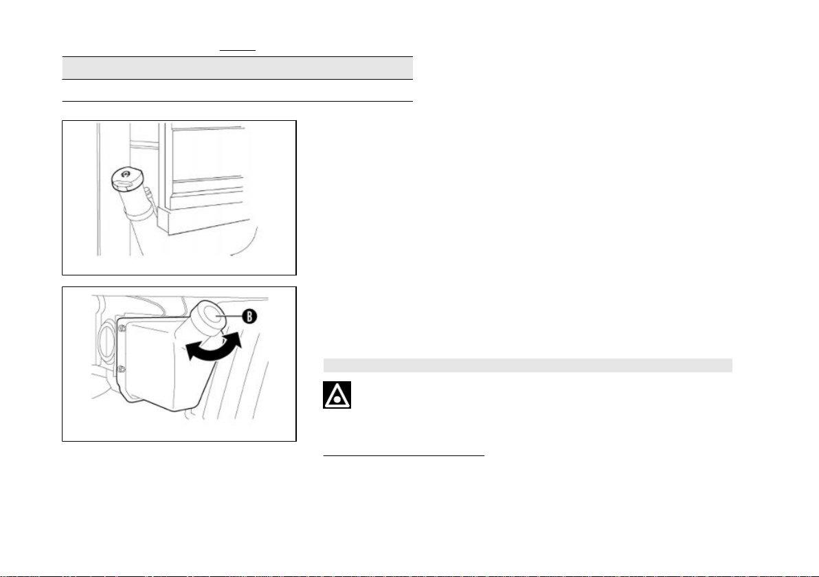
Oil tank (for petrol versions)
The oil tank is provided with a light reserve indicator on the instrument panel.
To top up, remove cap «B» and pour in new oil.
CAUTION
03_02
USING OTHER TYPES OF OIL CAN COMPROMISE ENGINE DURABILITY.
Recommended products
AGIP CITY TEC 2T
Oil for 2-stroke petrol engines
JASO FC, ISO-L-EGD Specifications
16
Page 17
3 Vehicle use
Characteristic
Mixer oil (2.0 l)
RESERVE: 0.6 l
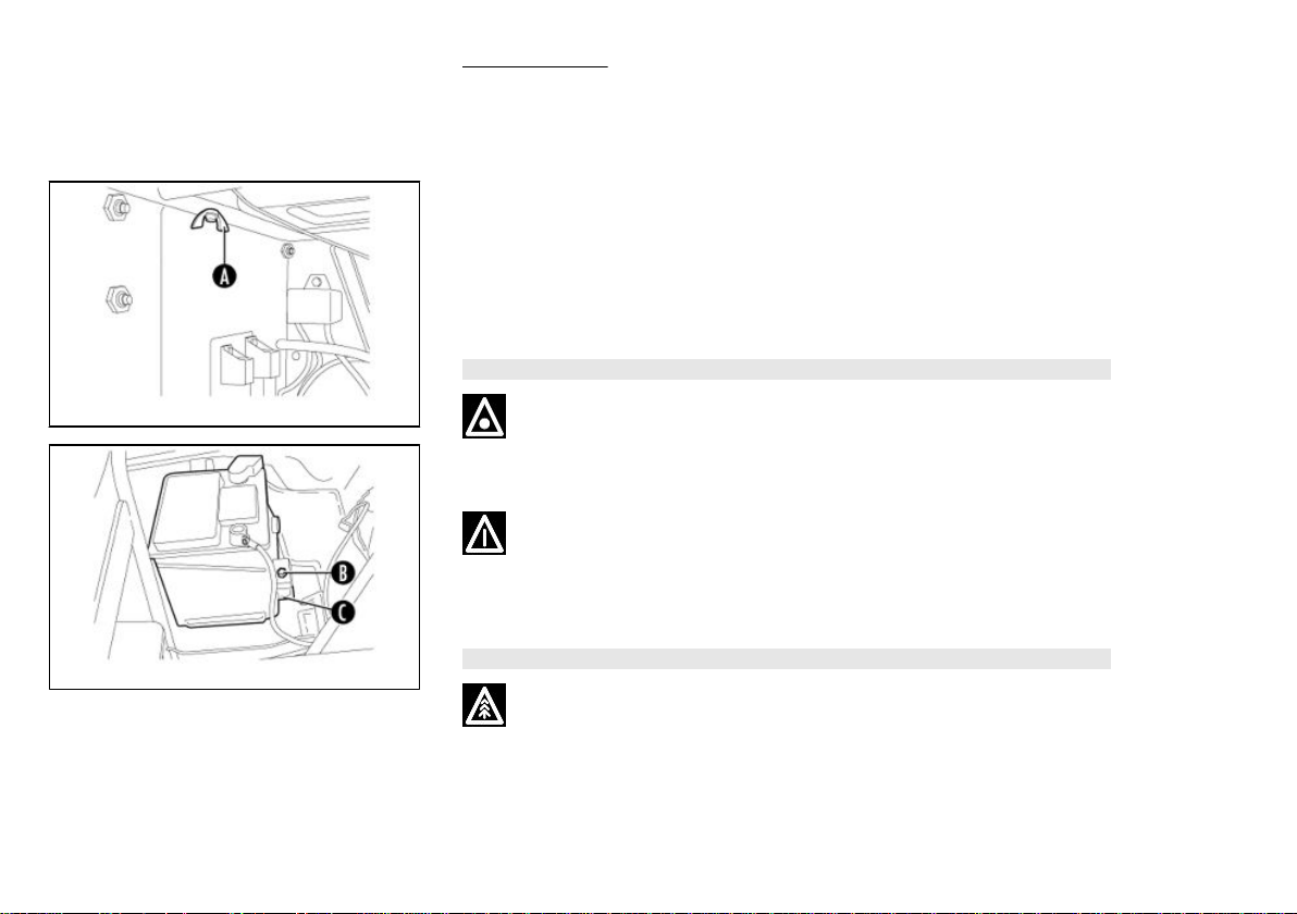
Removing the battery
The battery is located under the seat. The latter can be easily tilted removing the two
nuts «A» located at the two ends below the seat, as shown in the figure.
If it is necessary to remove the battery from its housing (for replacing or charging it),
disconnect the cables, remove nut «B» and release the battery from the locking
bracket «C».
CAUTION
03_03
NEVER DISCONNECT THE BATTERY WHEN THE ENGINE IS RUNNING TO
AVOID DAMAGING THE ELECTRICAL SYSTEM.
BATTERY ELECTROLYTE CONTAINS SULPHURIC ACID: AVOID CONTACT
WITH EYES, SKIN AND CLOTHES. IN THE EVENT OF ACCIDENTAL CONTACT,
RINSE WITH PLENTY OF WATER AND SEEK MEDICAL ADVICE
WARNING
03_04
USED BATTERIES ARE HARMFUL FOR THE ENVIRONMENT AND MUST BE
COLLECTED AND DISPOSED OF IN COMPLIANCE WITH THE LAW.
17
Page 18
Installing a new battery
Make sure the terminals are fitted correctly. The battery is an electrical device that
requires careful checks and diligent maintenance.
CAUTION
DO NOT INVERT THE POLARITIES: DANGER OF SHORT-CIRCUIT AND FAULTS
IN THE ELECTRICAL DEVICES.
Checking electrolyte level
The electrolyte level must be checked frequently and must reach the maximum level.
Top up exclusively with distilled water.
If the battery requires topping up too frequently, check the electrical system - the battery is probably working in overload conditions, which will lead to rapid deterioration.
Before starting the engine
- Ensure that the parking brake is released.
- Ensure that the reverse gear control lever is forward or backward according to
whether you want to move forward or in reverse.
- Ensure that the gear control lever is in neutral position: position N for the handlebar
version, central lever position for the steering wheel version.
THIS PRELIMINARY OPERATION IS NOT REQUIRED IN THE STEERING WHEEL
DIESEL VERSION.
18
Page 19
3 Vehicle use
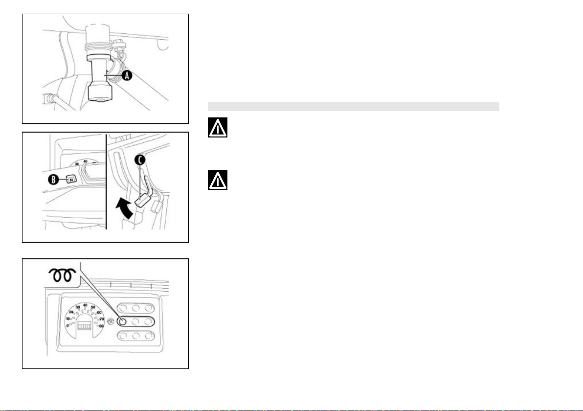
Engine start up (03_05, 03_06)
Engine ignition (gasoline version)
Open the fuel cock «A» (turn it counter clockwise to open and clockwise to close).
With cold engine, pull the starter lever «C» and insert the start key into the key switch,
then turn it to position 2 and at the same time press the accelerator control.
After start up, release the key that will automatically return to position 1.
WARNING
03_05
EXHAUST GASES ARE TOXIC. DO NOT START THE ENGINE IN A CLOSED
PLACE.
WHEN THE ENGINE IS ON, DO NOT HANDLE PARTS AND CONNECTIONS OF
THE ELECTRIC SYSTEM, ESPECIALLY THE SPARK PLUG CABLE.
03_06
Engine start up (03_06, 03_07)
Engine ignition (diesel version)
Introduce the start key into the switch and move it to position 1. On the instrument
panel, the glow plug preheat indicator will light up. The hotter the engine, the sooner
the indicator will turn off. Then move the key to position 2 while pressing the accelerator control at the same time. After start up, release the key that will automatically
return to position 1.
03_07
19
Page 20
WARNING
EXHAUST GASES ARE TOXIC. DO NOT START THE ENGINE IN A CLOSED
PLACE.
Engine start up (03_07, 03_08)
Starting off (versions with handlebar)
With idle engine, pull the clutch lever «A» and turn the gear knob to the 1st gear
(position 1 on the gear indicator «B »). To start off, release the clutch lever «A»
smoothly and accelerate by turning the throttle twist grip «C».
WARNING
03_08
03_09
EXHAUST GASES ARE TOXIC. DO NOT START THE ENGINE IN A CLOSED
PLACE.
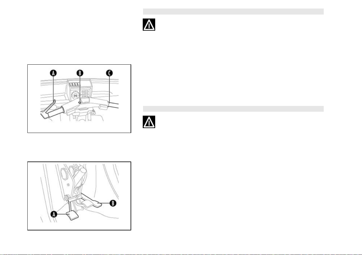
Engine start up (03_08, 03_09)
Start-up (handlebar versions)
With idle engine, press the clutch pedal «A» and engage the first gear with the gearbox
lever. Gently release the clutch pedal while gradually pressing the accelerator pedal
«B».
20
Page 21

Stopping the engine
3 Vehicle use
Stopping the engine (handlebar)
Before stopping the engine, shift to neutral (position «N» on the gear indicator « B »).
Then turn the ignition key to «A».
Stopping the engine (steering wheel)
Before stopping the engine, move the gearbox to neutral (central position), then turn
the switch key to position «A».
Starting difficulties
Engine starting difficulties (gasoline version)
Possible causes and suggested actions:
- Carburettor flooded.
Close the fuel cock, turn the start key to position "1"; with closed starter open the gas
thoroughly and actuate the key switch, moving it to position "2"; open the fuel cock
again and move the key switch to position "2". In any case, do not try starting for more
than 5-6 times.
- Dynamotor or battery inefficiency.
Use an auxiliary battery with equivalent or slightly higher specifications with respect
to the original battery.
If you need to bump start the vehicle (by pushing or towing), follow these instructions:
engage a high gear (2nd or 3rd), do not exceed 20 kph (even when freewheeling),
release the clutch pedal or lever gradually.
21
Page 22
03_10
Before performing this operation, check the reverse lever position. If you cannot start
the engine even with the procedure described above, contact an Authorised PIAG-
GIO Service Centre.
CAUTION
NEVER STRESS THE ENGINE AT LOW TEMPERATURES IN ORDER TO AVOID
POSSIBLE DAMAGE. WHEN DRIVING DOWNHILL, DO NOT EXCEED TOP
SPEED OR THE ENGINE COULD BE DAMAGED BY PROLONGED OVERREVVING.
CAUTION
•
AFTER A LONG JOURNEY ALLOW THE ENGINE TO RUN AT IDLE
SPEED FOR A FEW SECONDS BEFORE SWITCHING IT OFF.
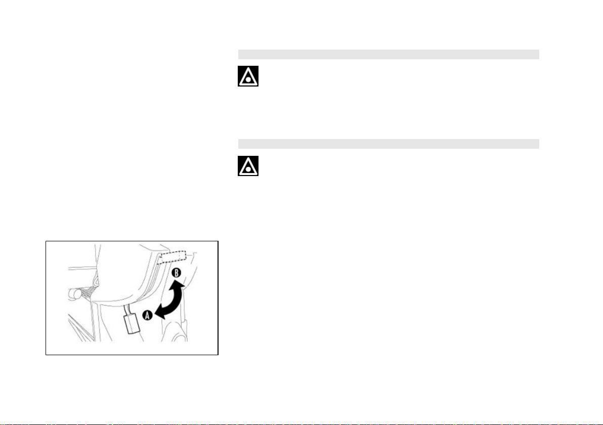
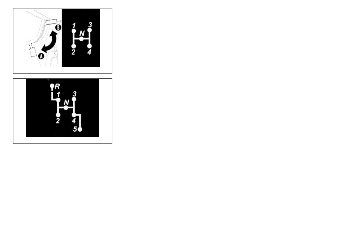
Gear position (03_10, 03_11, 03_12)
To reverse the vehicle, proceed as follows:
1. Stop the vehicle completely and turn the gear selector to neutral (position «N» on
the gear indicator «B») while the engine is idling;
2. For gasoline versions, lift the reverse gear control lever from position «A» to position
«B».
3. Diesel versions are not equipped with a reverse gear control lever.
4. Use the gear control lever to engage gears; («1stgear» for the gasoline version,
«R» for the handlebar version), and gently release the clutch pedal while gradually
pressing the accelerator pedal.
22
Page 23
3 Vehicle use
5. To shift from reverse gear to the forward gears repeat the previously described
procedures and move the reverse gear control lever to the «A» position (in the gasoline version and in the handlebar version).
Note: in the diesel handlebar version, once the reverse gear control lever has been
moved to the «B» position, both the reverse gear and the «1st gear» can be used for
vehicle parking manoeuvring; engagement of higher gears remains disabled until the
reverse gear control lever is set to the «A» position.
03_11
03_12
Driving Tips
Follow these simple recommendations to use your vehicle every day, confidently and
safely.
Your ability and your mechanical knowledge form the basis of safe riding. Practice
driving in a traffic-free area until you acquire a good knowledge of the vehicle.
1. Always drive within the limits of your ability, strictly following the road regulations of
the country where you are driving.
23
Page 24

2. Carefully adjust the position of rear-view mirrors, to easily check the road behind
you.
3. Ensure nothing hinders the pedals stroke (mats, etc.)
4. Ensure that headlights are working properly.
5. To start the vehicle, with idle engine, engage the first gear and gently release the
clutch lever, accelerating at the same time.
6. Reduce speed on badly surfaced roads and drive with caution.
7. Do not brake fully on wet, unsurfaced or slippery roads.
8. Do not shift down when the engine is running at high revs to avoid dangerous over-
revving.
9. On a downhill, do not keep the gearbox to neutral position or the engine off, but
decrease speed closing the accelerator. To facilitate the decrease of speed, use the
brakes without pulling them for too long, to prevent dangerous overheating that would
decrease their efficiency. Shift down to increase the engine brake effect.
10. For rapid pick-up, e.g. for overtaking, shift down a gear to employ all the required
power.
11. When driving up demanding slopes, shift down to employ all the required power.
12. Check that the load is evenly distributed on the loading body, and do not exceed
the provided loads (see chapter: "Technical data -performance") to prevent tilting while
turning on a corner.
ALWAYS DRIVE YOUR VEHICLE WITHIN THE LIMITS OF YOUR ABILITY. DRIVING WHILE DRUNK OR UNDER THE EFFECT OF DRUGS OR CERTAIN MEDICINES IS EXTREMELY DANGEROUS AND INFRINGES THE ROAD REGULATIONS.
24
Page 25

3 Vehicle use
ANY CHANGES TO VEHICLE PERFORMANCE, AS WELL AS ALTERATIONS TO
ORIGINAL STRUCTURE PARTS, RENDERS THE VEHICLE NO LONGER CONFORMING TO THE APPROVED TYPE AND THEREFORE DANGEROUS FOR
DRIVING SAFELY.
25
Page 26

26
Page 27

Ape TM - Ape TM Diesel
Chap. 04
Doors and locks
27
Page 28
04_01
04_02
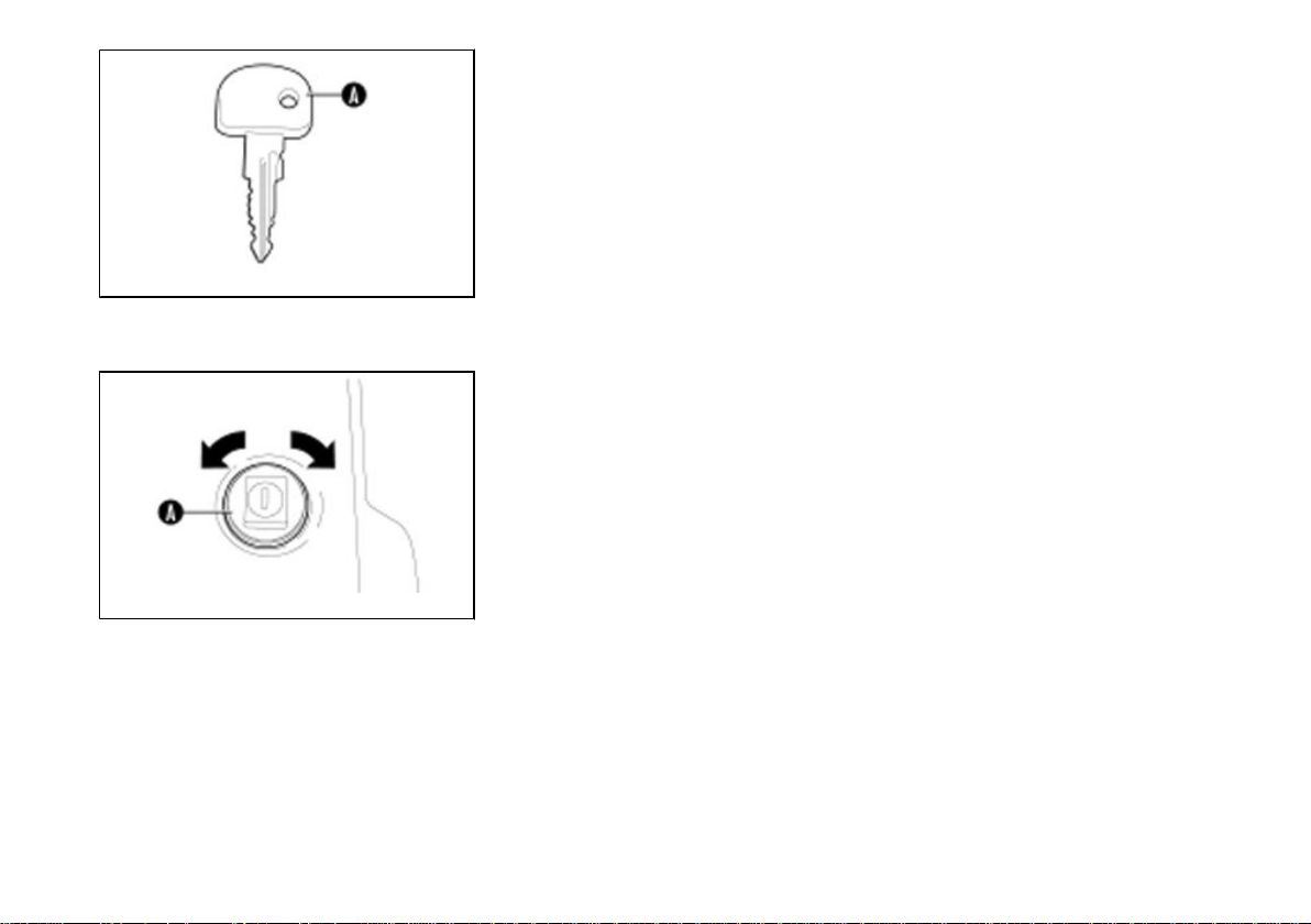
Keys (04_01)
The vehicle is supplied with two copies of the key.
«A»: key for the ignition and start-up switch, the door lock and the fuel tank cover.
The code numbers, in fact, are the only way to identify the key for future copies.
YOU SHOULD KEEP A DUPLICATED KEY AND ITS CORRESPONDING CODE IN
ANY PLACE OTHER THAN THE VEHICLE.
Door locking/unlocking by key (04_02, 04_03)
The doors are provided with antitheft device. To open turn the key clockwise and press
button «A». To close turn the key anticlockwise.
28
Page 29
4 Doors and locks
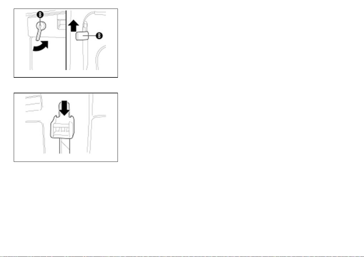
To open both doors from the inside, use the special release control «B».
For the handlebar version, the release control «B» must be lifted, while for the steering
wheel version it must be pushed rightwards.
MAKE SURE IT IS SAFE TO OPEN THE DOORS BEFORE OPENING THEM. BEFORE STARTING OFF, MAKE SURE THE DOORS ARE CLOSED AND LOCKED.
THIS PRECAUTION WILL ENSURE THEY DO NOT OPEN ACCIDENTALLY
WHICH WOULD BE A HAZARD FOR THE DRIVER
04_03
Front door windows (04_04)
To open the windows, press the release lever while moving the handle downwards.
(7 fixed positions are available).
To close the windows, move the handle to "travel end top" position.
04_04
29
Page 30
04_05
Engine inspection port (04_05)
Lower the rear side board and grip the handle «A» pulling it upwards to release the
retain clips «B».
On the vehicles with loading body in light alloy with tilting, to access the engine compartment it is necessary to lower the side and rear boards and then tilt the loading
body.
Use the special safety bar to secure the loading body in tilted position.
NEVER WORK UNDERNEATH THE LOADING BODY WHEN IT IS TILTED WITHOUT HAVING FIRST SECURED THE SAFETY BAR. DANGER OF SERIOUS INJURY.
30
Page 31

Ape TM - Ape TM Diesel
Chap. 05
Seats and safety
belts
31
Page 32

Using the safety belts
Observe the following suggestions for using the seat belts correctly. Failure to follow
these instructions may lead to severe injury in the event of an accident or sudden
braking. Check the seat belts periodically to ensure proper functioning. If its operation
appears faulty, have it checked at an Authorised PIAGGIO Service Centre immediately.
Pregnant women: PIAGGIO recommends using the seat belt. The waist height seat
belt length should adhere snugly to your body as low as possible (on the hips) and not
at your waist. Ask your doctor for advice.
Injured people: PIAGGIO recommends using the seat belt. Ask your doctor for advice.
WARNING
THE SAFETY BELTS ARE DESIGNED TO EXERT THEIR ACTION ON THE BONE
STRUCTURE OF YOUR BODY. THE DIFFERENT BELT SECTIONS SHOULD FIT
SNUGLY TO THE PELVIS, THE CHEST AND SHOULDERS. DO NOT WEAR THE
SECTION WHICH IS SUPPOSED TO FIT ON THE HIPS OVER THE ABDOMEN.
SAFETY BELTS SHOULD BE ADJUSTED TO FIT SNUGLY AND SHOULD BE
ADAPTED TO THE PERSON WEARING THEM, SO AS TO OFFER THE PROTECTION THEY ARE DESIGNED FOR. A LOOSE BELT WOULD CONSIDERABLY
REDUCE PROTECTION TO THE PASSENGER WEARING IT. BE CAREFUL NOT
TO DAMAGE BELTS WHEN CLOSING THE DOORS. DO NOT REMOVE BELTS
FOR CLEANING. WASH THEM WITH WATER AND NEUTRAL SOAP, RINSE AND
LET DRY IN A WARM PLACE. PAY SPECIAL ATTENTION NOT TO DAMAGE THE
SEAT BELTS WITH CLEANING PRODUCTS, OIL, ABRASIVE DETERGENTS,
CHEMICAL AGENTS OR BATTERY FLUIDS
.
32
Page 33

5 Seats and safety belts
WARNING
AFTER A SEVERE ACCIDENT, IT IS ESSENTIAL TO HAVE THE ENTIRE SEAT
BELT ASSEMBLY REPLACED, EVEN IF IT MAY NOT APPEAR DAMAGED. DO
NOT WEAR A TWISTED SEAT BELT. DO NOT WEAR THE SEAT BELT WITH THE
SHOULDER LENGTH UNDER YOUR ARM OR BEHIND YOUR BACK. DO NOT
FASTEN THE SEAT BELT OVER HARD OR FRAGILE OBJECTS, SUCH AS
GLASSES, JEWELLERY, PENS, KEYS. DO NOT WEAR THE SEAT BELT OVER
VERY THICK CLOTHES, AS THIS MAY PREVENT IT FROM BEING POSITIONED
CORRECTLY. DO NOT MODIFY OR DISASSEMBLE THE SEAT BELT ASSEMBLY. AFTER AN ACCIDENT OF A CERTAIN SEVERITY, WE RECOMMEND THAT
YOU HAVE THE SEAT BELT WHICH WAS BEING WORN REPLACED AT AN AUTHORISED PIAGGIO SERVICE CENTRE, EVEN IF IT DOES NOT APPEAR DAMAGED.
Fasting the safety belt (05_01)
Take the metal tongue from its housing.
Insert the metal tongue in the buckle until it clicks.
CAUTION
05_01
TO GUARANTEE THE OPTIMAL PERFORMANCE OF THE SEAT BELT, AFTER
HAVING INSERTED THE METAL TONGUE INTO THE BUCKLE, CHECK IT IS SECURELY BLOCKED AND THE SEAT BELT IS NOT TWISTED.
33
Page 34

05_02
05_03
Adjusting the safety belt (05_02)
Position the seat belt as low as possible on your hips and not at your waist.
Adjust the seat belt so that you can slide your fist between the belt and your chest.
Hold the anchoring at a right angle with respect to the belt and pull the belt to lengthen
or shorten it.
A: wrong
B: right
To release the safety belt (05_03)
Press the button. Insert the metal tongue in its housing when it is not in use.
CAUTION
TO PREVENT DAMAGING SEAT BELTS CHECK THEY DO NOT REMAIN
PINCHED BETWEEN A DOOR AND THE CAR BODY, OR BEHIND THE SEAT
BACK.
34
Page 35

Ape TM - Ape TM Diesel
Chap. 06
Instrument panel
and controls
35
Page 36

Handlebars (06_01)
Apetm
1. External light control switch
2. Tachometer and odometer
3. Ashtray
4. Gear indicator
5. Clutch lever
6. Cigar lighter
7. Turn indicator selector
8. Reverse gear command lever
9. Key switch
10. Emergency or parking brake
11. Heater control lever (red)
12. Starter lever (only in the gasoline version)
13. Brake pedal
14. Headlight switch
15. Horn button
16. Accelerator control
17. Light indicators unit
18. Emergency light switch
19. Rear fog light switch
20. Windscreen wiper control switch
36
Page 37

6 Instrument panel and controls
06_01
Handlebars (06_01, 06_02)
ApetmD
1. External light control switch
2. Tachometer and odometer
3. Ashtray
4. Gear indicator
5. Clutch lever
6. Cigar lighter
37
Page 38

7. Turn indicator selector
8. Reverse gear command lever
9. Key switch
10. Emergency or parking brake
11. Heater control lever (red)
12. Airflow deflector lever: windscreen - floor heating
13. Brake pedal
14. Headlight switch
15. Horn button
16. Accelerator control
17. Light indicators unit
18. Heater fan switch
19. Rear fog light switch
20. Windscreen wiper control switch.
21. Emergency light switch
22. Body tilting button (where available).
38
Page 39

6 Instrument panel and controls
06_02
Steering wheel (06_03)
Apetm
1. Steering wheel
2. Flashing light switch lever
3. Light and horn switch lever
4. Key switch
5. Clutch pedal
6. Brake pedal
39
Page 40

7. Accelerator pedal
8. External light control switch
9. Windscreen wiper control switch
10. Reverse gear control lever
11. Gearbox control lever
12. Emergency or parking brake
13. Heating control lever (red)
14. Starter lever (only gasoline version) (black)
15. Rear fog light switch
16. Cigar lighter
17. Emergency light switch
18. Ashtray
19. Light indicators unit
20. Tachometer and odometer
40
Page 41

6 Instrument panel and controls
06_03
Steering wheel (06_03, 06_04)
ApetmD
1. Steering wheel
2. Flashing light switch lever
3. Light and horn switch lever
4. Key switch
5. Clutch pedal
6. Brake pedal
41
Page 42

7. Accelerator pedal
8. External light control switch
9. Windscreen wiper control switch
10. Reverse gear control lever
11. Gearbox control lever
12. Emergency or parking brake
13. Heating control lever (red)
14. Airflow deflector lever: windscreen - floor heating
15. Rear fog light switch
16. Cigar lighter
17. Heater fan switch
18. Ashtray
19. Light indicators unit
20. Tachometer and odometer
21. Emergency light switch
22. Body tilting button (where available).
42
Page 43

6 Instrument panel and controls
06_04
Controls (06_05, 06_06, 06_07, 06_08, 06_09)
HANDLEBAR VERSION - GASOLINE
External light control switch «A»
0 = Lights off;
1 = Front and rear side/taillights and instrument panel lights on;
2 = Headlights (high or dipped beams on).
43
Page 44

06_05
Windscreen wiper control switch «B»
0 = Disabled;
1 = Windscreen wiper enabled.
2 = Windscreen wiper + sprayer enabled.
Light selector «A»
1 = High beams on.
2 = Dipped beams;
THE SWITCH POSITIONS ARE SUBJECT TO THE OUTSIDE LIGHT CONTROL
SWITCH POSITION.
Horn button
B = horn button.
06_06
44
Page 45

6 Instrument panel and controls
Turn indicator selector «C»
0 = Lights off;
S = Left turn indicators flashing;
D = Right turn indicators flashing.
06_07
Emergency light switch «B»
0 = Lights off;
1 = Direction indicators flashing
Rear fog light switch «A»
0 = Light off;
1 = Rear fog light on.
06_08
STEERING WHEEL VERSION - GASOLINE
Light and horn switch lever «A»
With external light control switch «B» in position enabled.
45
Page 46

1 = Taillights on;
2 = Dipped beams on;
3 = High beams on.
To actuate the horn, press lever «A» upwards.
THE LIGHT SWITCH LEVER POSITIONS ARE SUBJECT TO THE OUTSIDE LIGHT
CONTROL SWITCH POSITION.
Flashing light switch lever «C»
0 = Lights off;
S = Left turn indicators flashing;
D = Right turn indicators flashing.
External light control switch «A»
0 = Lights off;
1 = Lights on.
Windscreen wiper control switch «B»
0 = Disabled;
1 = Windscreen wiper enabled.
2 = Windscreen wiper + sprayer enabled.
Rear fog light switch «C»
0 = Light off;
46
Page 47

1 = Rear fog light on.
6 Instrument panel and controls
Emergency light switch «D»
0 = Lights off;
1 = Direction indicators flashing
Cigar lighter«E»
Press the lighter button and wait until it automatically returns to its initial position. The
lighter is ready for use.
06_09
Controls (06_09, 06_10, 06_11, 06_12, 06_13, 06_14)
HANDLEBAR VERSION - DIESEL
External light control switch «A»
0 = Lights off;
1 = Front and rear side/taillights and instrument panel lights on;
2 = Headlights (high or dipped beams on).
47
Page 48

06_10
Windscreen wiper control switch «B»
0 = Disabled;
1 = Windscreen wiper enabled.
2 = Windscreen wiper + sprayer enabled.
Light selector «A»
1 = High beams on.
2 = Dipped beams;
THE SWITCH POSITIONS ARE SUBJECT TO THE OUTSIDE LIGHT CONTROL
SWITCH POSITION.
Horn button
B = horn button.
06_11
48
Page 49

6 Instrument panel and controls
Turn indicator selector «C»
0 = Lights off;
S = Left turn indicators flashing;
D = Right turn indicators flashing.
06_12
Rear fog light switch «A»
0 = Light off;
1 = Rear fog light on.
Heater fan switch «B»
0 = Fan off
1 = First gear
2 = Second gear
Emergency light switch «A»
0 = Lights off;
1 = Direction indicators flashing
49
Page 50

06_13
Body tilting button «B» (where available)
0 = Body down
1 = Body up
In order to improve safety and prevent unintentional operations, the lifting controls only
becomes live after releasing the safety lever on the right hand side at the back of the
cabin.
Remember to bring the safety lever back onto the 'blocked' position once all tilting
operations are completed.
•
THE BODY LIFTING OPERATIONS MUST BE CARRIED OUT WITH THE
VEHICLE STOPPED AND THE EMERGENCY/PARKING BRAKE ACTIVATED.
STEERING WHEEL VERSION - DIESEL
Light and horn switch lever «A»
With external light control switch «B» in position enabled.
1 = Taillights on;
2 = Dipped beams on;
3 = High beams on.
To actuate the horn, press lever «A» upwards.
THE LIGHT SWITCH LEVER POSITIONS ARE SUBJECT TO THE OUTSIDE LIGHT
CONTROL SWITCH POSITION.
Flashing light switch lever «C»
0 = Lights off;
S = Left turn indicators flashing;
50
Page 51

D = Right turn indicators flashing.
6 Instrument panel and controls
External light control switch «A»
0 = Lights off;
1 = Lights on.
Windscreen wiper control switch «B»
0 = Disabled;
1 = Windscreen wiper enabled.
2 = Windscreen wiper + sprayer enabled.
Rear fog light switch «C»
0 = Light off;
1 = Rear fog light on.
Heater fan switch «D»
0 = Fan off
1 = First gear
2 = Second gear
51
Page 52

06_14
Cigar lighter«E»
Press the lighter button and wait until it automatically returns to its initial position. The
lighter is ready for use.
Emergency light switch «F»
0 = Lights off;
1 = Emergency light on.
Body tilting button «G»
0 = Body down
1 = Body up
52
Page 53

6 Instrument panel and controls
06_15
06_16
In order to improve safety and prevent unintentional operations, the lifting control only
becomes live after releasing the safety lever on the right hand side at the back of the
cabin.
Remember to bring the safety lever back onto the 'blocked' position once all tilting
operations are completed.
•
TIPPING ACTIONS OF THE PLATFORM MUST BE CARRIED OUT WHEN
THE VEHICLE IS STOPPED AND THE HANDBRAKE ENGAGED.
Ignition switch (06_16, 06_17)
According to the version (steering wheel or handlebar), the key switch is on the left of
the steering wheel or on the front side, on the steering column cover.
The key can turn to 3 different positions:
0 = Ignition off, key can be removed, steering locked.
1 = Running position - arrangement of utilities and external lights and start up of pre-
heating glow plug (for diesel versions).
2 = Engine start up (after start up, the key automatically returns to the running position
"1").
Locking the steering (antitheft): with the key switch set to 0, extract the key and turn
the steering wheel leftwards (travel end).
Unlocking the steering: insert the key and turn it to 1.
Steering wheel lock (antitheft): with the key switch set to 0, extract the key and turn
the steering wheel to lock it.
Steering wheel release: insert the key and turn it to 1.
53
Page 54

DO NOT TURN THE KEY TO POSITION 0 WHILE DRIVING.
WARNING
06_17
SHOULD THE STARTING DEVICE BE TAMPERED WITH (E.G. A THEFT ATTEMPT) HAVE IT CHECKED AT THE EARLIEST OPPORTUNITY BY A DEALER
OR AN AUTHORISED PIAGGIO SERVICE CENTRE BEFORE YOU START DRIVING AGAIN.
WHEN YOU LEAVE THE VEHICLE, ALWAYS REMOVE THE KEY TO PREVENT
SOMEBODY FROM ACCIDENTALLY ACTUATING THE CONTROLS. ENGAGE
THE PARKING BRAKE AND THE FIRST OR REVERSE GEAR ACCORDING TO
WHETHER THE VEHICLE IS UPHILL OR DOWNHILL. SUITABLY TURN THE
STEERING WHEEL TO PREVENT BLOCKING THE ROAD IN CASE OF AN ACCIDENTAL RELEASE OF THE EMERGENCY OR PARKING BRAKES.
54
Page 55

Ape TM - Ape TM Diesel
Chap. 07
Gauges and
Warning Lights
55
Page 56

07_01
Instrument unit and indicators (07_01)
A = Speedometer, odometer/mileometre.
B = Preheat glow plug indicator (only on diesel versions - amber colour).
C = Flashing lights on indicator (green colour).
D = High beams on indicator (blue colour).
E = Taillights on indicator (green colour).
F = Rear fog light on indicator (amber colour).
G = High water temperature indicator (only on diesel versions - red colour).
H = Oil reserve indicator (for gasoline versions). Inadequate oil pressure indicator (for
diesel versions).
I = Fuel reserve indicator (amber colour).
L = Battery charge voltage low indicator (red colour).
56
Page 57

Ape TM - Ape TM Diesel
Chap. 08
Air control
system
57
Page 58

08_01
08_02
Heating (08_01)
Cabin heater controls (gasoline):
Lever «A» (with red grip): in position 1.
Control bar «B»: in position 1 (travel end back) located below the driver's seat to allow
opening diaphragm «C».
Shuttering outlets «D» in position 1 (OPEN).
The cabin heater can be disabled by the shuttering outlets «D» or directly by returning
lever «A» to neutral position (position 2).
Heating (08_01, 08_02)
Cabin heating controls (diesel):
Lever «A» (with red grip): position 1, warm air.
Lever «B»: position 1, warm air towards feet.
Lever «B»: position 2, warm air towards the windscreen.
58
Page 59

8 Air control system
Heating and demisting (08_03)
Cabin defrosting/heating controls (gasoline):
Control bar «B» in position 2 (travel end forward).
Shuttering outlets «D» in position 1 (OPEN).
08_03
Heating and demisting (08_03, 08_04)
Cabin defrosting/heating controls (diesel):
Control bar «B» in position 2.
08_04
Demisting (08_05)
Cabin defrosting controls (gasoline):
Control bar «B» in position 2 (travel end forward).
Shuttering outlets «D» in position 2 (CLOSED).
The hot air flow is thus sent to the windscreen only, through the two outlets shown in
the figure.
08_05
59
Page 60

08_06
Demisting (08_05, 08_06)
Cabin heating controls (diesel):
Control lever «B» in position 1.
The hot air flow may be partitioned through the two outlets «D».
60
Page 61

Ape TM - Ape TM Diesel
Chap. 09
Mirrors and
Window Glasses
61
Page 62

9_01
Adjusting the mirror (9_01)
Rear-view mirrors are adjusted by moving the mirror body manually until the ideal
angle is obtained to guarantee full visibility.
CAUTION
NEVER ADJUST MIRRORS WHILE DRIVING AS YOU MAY LOSE CONTROL OF
THE VEHICLE.
Wipers and Brushes (9_02, 9_03)
Blade
•
Clean regularly the rubber part with specific products.
•
Replace the blade if the rubber is misshapen or worn. In any case, blades
should be replaced approximately once a year.
Some simple recommendations can minimise the possibility of damage to the blade:
•
- If the temperature is below zero, make sure the rubber part is not frozen to
the windscreen. If required, use a de-icing product to release the blade.
•
- Remove any snow from the windscreen: this will protect the blade and avoid
overloading and overheating the electric motor.
•
Do not operate the windscreen wiper on a dry windscreen.
DRIVING WITH A WORN WINDSCREEN WIPER BLADE CAN BE EXTREMELY
DANGEROUS AS VISIBILITY IS DECREASED IN POOR WEATHER CONDITIONS.
62
Page 63

9 Mirrors and Window Glasses
9_02
9_03
Replacing the windscreen wiper blade
Replace the windscreen wiper blade as follows:
•
Lift the windscreen wiper arm "A" and position the blade so that it forms a
right angle with the arm;
•
Press retainer tab "B" of the latching spring and extract the blade for arm
"A";
•
Fit a new blade. Insert the tab in its seat on the arm. Make sure it is locked.
Nozzles
•
If there is no jet of fluid, first of all check whether the windscreen washer
reservoir is full.
•
Check whether the holes «A» are clogged. If so, open them with a pin.
•
Direct the windscreen washer nozzles so that the jets are directed towards
the highest position of the blade stroke.
63
Page 64

64
Page 65

Ape TM - Ape TM Diesel
Chap. 10
Inside
equipment
65
Page 66

66
Page 67

Ape TM - Ape TM Diesel
Chap. 11
Electrical
system
67
Page 68

Fuel version
The power for the lighting and indication system devices is provided in direct current
by a dynamotor/battery unit, with a voltage regulator separated by the remote control
switch unit, both installed under the seat in the compartment. The dynamotor acts as
a generator-dynamo and as a starter motor: in particular, upon start-up, it absorbs
current from the battery and operates as an electric motor.
After starting the engine and reaching a certain speed, the dynamotor acts as a normal
dynamo, charging the battery and powering the vehicle system.
Electric characteristic
Battery
12V-32Ah
Diesel version
The power for the lighting and indication system devices is provided in direct current
by a special battery.
The engine is equipped with an 18-pole rotor stator unit, three-phase, 330W MAX.
The preheating device for starting the engine, which is fitted with a light indicator,
controls the special preheat glow plug.
FOR ESPECIALLY COLD AREAS, WE RECOMMEND INSTALLING A 12V-60AH
BATTERY.
WHEN INTERVENING ON THE ELECTRICAL SYSTEM, MAKE ESPECIALLY
SURE THAT THE WIRES LEADING TO THE ELECTRONIC CONTROL UNIT ARE
CORRECTLY CONNECTED AND RESPECT THE COLOUR CODING GIVEN ON
THE CONTROL UNIT.
Electric characteristic
Battery
68
Page 69

11 Electrical system
12V-50Ah
69
Page 70

70
Page 71

Ape TM - Ape TM Diesel
Chap. 12
Emergency
71
Page 72

12_01
12_02
Wheel replacement (12_01, 12_02)
The tyre replacement operation and the use of jack require some precautions which
are given below.
WARNING
SIGNAL THE PRESENCE OF THE VEHICLE AS PRESCRIBED BY THE HIGHWAY
CODE IN FORCE.
PLACE THE JACK IN THE POSITIONS SHOWN SO AS NOT TO DAMAGE MECHANICAL PARTS OR THE BODY
WARNING
WHENEVER POSSIBLE, REPLACE TYRES WITH THE VEHICLE ON LEVEL
GROUND. IF THE GROUND IS SLOPING OR BADLY SURFACED, PUT WEDGES
OR ANY OTHER SUITABLE MATERIAL UNDER THE WHEELS TO BLOCK THE
VEHICLE. DO NOT GREASE BOLT THREADS BEFORE REFITTING: THEY
COULD COME UNDONE SPONTANEOUSLY.
NEVER TAMPER WITH THE INFLATION VALVE. DO NOT PLACE TOOLS BETWEEN RIM AND TYRE.
Maintenance instructions
They are located into the compartment, below the seat.
72
Page 73

CAUTION
12 Emergency
THE JACK CAN ONLY BE USED TO REPLACE THE WHEELS. NEVER USE THE
JACK TO PERFORM REPAIRS UNDER THE VEHICLE. THE VEHICLE MAY FALL
IF THE JACK IS NOT POSITIONED CORRECTLY
CAUTION
PERIODICALLY CHECK TYRE PRESSURE ACCORDING TO THE VALUES GIVEN IN THE: «MAINTENANCE
».
73
Page 74

74
Page 75

Ape TM - Ape TM Diesel
Chap. 13
Maintenance
75
Page 76

13_01
13_02
Check engine oil level (13_01)
Engine oil level check (diesel version)
To check the engine oil level, proceed as follows:
1. Check with engine off and vehicle on a flat surface;
2. Extract the level bar from the rear side of the vehicle and check that the level is
between the MIN and MAX positions;
3. If a top up is required, add new oil by the filler located into the engine compartment;
WARNING
TOP UP USING OIL OF THE SAME TYPE ALREADY CONTAINED INTO THE ENGINE.
Oil change and oil filter replacement (13_02, 13_03, 13_04)
Replacing the engine oil (diesel version)
To replace the engine oil proceed as follows:
1. Loosen the drainage cap «A» and drain the oil;
2. When drainage is complete, tighten cap «A», remove cap «B» and pour new oil by
the filler; the oil level must always be between the MIN and MAX positions marked on
bar «C»;
3. Periodically check the oil level;
76
Page 77

13 Maintenance
WARNING
REPLACE THE OIL WHEN THE ENGINE IS WARM.
CAUTION
13_03
13_04
RUNNING THE ENGINE WITH INSUFFICIENT LUBRICATION OR IMPROPER LUBRICANTS ACCELERATES THE WEAR OF ALL MOVING PARTS AND MAY
RESULT IN SERIOUS DAMAGES.
CAUTION
USED OIL IS HARMFUL TO THE ENVIRONMENT. WHEN REPLACING THE OIL,
WE SUGGEST TO CONTACT A PIAGGIO AUTHORISED SERVICE POINTS
EQUIPPED FOR DISPOSING SPENT OILS IN THE RESPECT OF NATURE AND
IN COMPLIANCE WITH THE LAWS IN FORCE.
Characteristic
new oil:
2.8 litres
77
Page 78

13_05
Oil change and oil filter replacement (13_04, 13_05)
Engine oil cartridge replacement (Diesel version)
To gain access to the oil cartridge proceed as follows:
1. Remove the engine inspection door (or lift the metal alloy plate);
2. Drain the engine crankcase;
3. Remove the filtering body «F»;
4. Lubricate the new cartridge seal and screw it in as far as it will go, and then tighten
it by hand by half a turn;
5. Fill up with fresh oil, then start the engine whilst inspecting for oil leaks.
WARNING
TO PREVENT DAMAGING THE ENGINE, FILL THE FILTER WITH NEW OIL BEFORE PROCEEDING TO THE REASSEMBLY.
IN CASE OF REPLACEMENT OF THE FILTER, THE AMOUNT OF OIL CONTAINED INTO THE CRANKCASE IS OF ABOUT 2.8 LITRES (THE TOTAL CIRCUIT
CAPACITY IS 3.5 LITRES).
WARNING
USING NON-ORIGINAL SPARES SERIOUSLY IMPAIRS THE VEHICLE PERFORMANCE AND LIFE.
78
Page 79

13 Maintenance
13_06
WARNING
TO DISPOSE OF OLD FILTERS, TURN TO A PIAGGIO SERVICE CENTRE. FOLLOW THE SPECIFIC ENVIRONMENT-RELATED REGULATIONS IN FORCE.
Checking the brake fluid level (13_06)
Checking level (gasoline version)
The rear brake fluid tank is located into the driver compartment, above the brake pedal.
Check the level as follows:
1. Stop the vehicle on level ground;
2. Check the oil level is between 1 cm under the surface of cap «A» (MAX level) and
1 cm over the bottom of the reservoir (MIN level).
If the oil is under the minimum level contact a PIAGGIO Dealer or Authorised Service
Centre to have the brake system checked.
Topping up brake fluid
To fill the reservoir, unscrew cap «A» and top up.
In normal climates, replace the fluid every 20,000 km or every 2 years.
Qualified and skilled personnel is required for this operation. We recommend you go
to a PIAGGIO Dealer or Authorised Service Centre.
Recommended products
AGIP DOT4 BRAKE FLUID
Brake fluid
79
Page 80

13_07
FMVSS DOT 4
Checking the brake fluid level (13_06, 13_07)
Level check (Diesel version)
The rear brake fluid reservoir is located inside the vehicle, underneath the cover on
the right-hand side of the instrument panel.
To check the level, remove the two fixing screws and the cover, then follow the procedure outlined in the previous paragraph.
CAUTION
ONLY USE DOT 4 CLASSIFIED BRAKE FLUIDS.
CAUTION
BRAKE FLUID IS HAZARDOUS: WASH WITH WATER IN THE EVENT OF ACCIDENTAL CONTACT.
CAUTION
BRAKING CIRCUIT FLUID IS VERY CORROSIVE; AVOID CONTACT WITH PAINTED PARTS.
THE BRAKING CIRCUIT FLUID IS HYGROSCOPIC, I.E., IT ABSORBS HUMIDITY
FROM THE SURROUNDING AIR. IF THE HUMIDITY IN THE BRAKE FLUID EX-
80
Page 81

13 Maintenance
13_08
13_09
CEEDS A CERTAIN VALUE, IT WILL LEAD TO INEFFICIENT BRAKING. NEVER
USE BRAKE FLUID FROM PREVIOUSLY OPENED OR PARTLY-EMPTY CONTAINERS.
Gear box oil level (13_08, 13_09, 13_10)
To check the gearbox oil, proceed as follows:
1. Check with engine off and vehicle on a flat surface;
2. Loosen the two screws fixing the SAS to the support bracket and move the SAS so
as to access the cap «A»;
3. Loosen the inspection cap «A», then check that the oil level is between the MIN
and MAX references on the bar contained into the cap;
4. If you need to top up the level, extract the cap with the bar and restore the level;
5. Replace the SAS to the original position.
TOP UP USING OIL OF THE SAME TYPE ALREADY CONTAINED INTO THE
GEARBOX.
81
Page 82

13_10
To replace the gearbox oil proceed as follows:
1. Remove the cap «A», loosen cap «B» and drain the oil; when drainage is complete,
replace cap «B».
2. Pour some oil into the top hole and let the engine run for a few seconds; then, drain
the crankcase again.
3. Refill with new oil, periodically checking the level with the bar until the mark MAX
is reached.
WARNING
REPLACE THE OIL WHEN THE ENGINE IS WARM.
•
AN EXCESSIVE AMOUNT OF OIL CAN SPILL OUT AND DIRTY THE ENGINE.
WARNING
•
USED OIL CONTAINS SUBSTANCES HARMFUL TO THE ENVIRONMENT. FOR OIL REPLACEMENT, CONTACT ANY AUTHORISED PIAGGIO SERVICE CENTRE AS THEY ARE EQUIPPED WITH LAW-ABIDING
ENVIRONMENTALLY- FRIENDLY OIL DISPOSAL SYSTEMS
Recommended products
AGIP ROTRA MP 80W-90
Oil with specifications SAE 80W-90, API GL-5
Gearbox oil
Characteristic
Oil amount for gasoline version:
82
Page 83

13 Maintenance
13_11
13_12
885 grams (approx. 1000 cm3)
Window washer fluid level (13_11)
Topping up windscreen washer fluid
The windscreen washer fluid reservoir is located inside the cab on the front right panel.
To fill the reservoir, unscrew cap «A» and top up. Use a specific detergent.
Cooled fluid (13_12)
Coolant top-ups (Diesel version)
Loosen the filler cap on the expansion tank.
Fill up the tank with coolant (permanent 50% water + ethyl glycol fluid recommended).
The correct level is indicated on the expansion tank by the LEVEL reference mark.
Circuit air-bleed: start the engine up and let it run at idle so to allow for any air bubble
trapped inside the circuit to leave the cooling system.
The coolant level will gradually decrease and then settle. Stop the engine and top-up
the circuit as explained in the previous paragraph. After a few hours of normal use,
check the level with the engine cold.
Cooling circuit hose inspection (every 10,000 Km)
83
Page 84

13_13
Check the coolant circuit hoses for signs of wear (alligatoring of the rubber) and also
check that all fittings are properly sealed. If any of the hoses is worn, please contact
your nearest Authorised Piaggio Service Centre to have it replaced.
Changing the engine cooling fluid
Drain the circuit completely and refill following the procedure given in the previous
paragraphs.
Checking and replacing the air cleaner element (13_13, 13_14)
Replacing the air filter (gasoline version)
To replace the air filter, proceed as follows:
1. Lower the rear side and remove the engine cover;
2. Loosen the three knobs «A» fixing the filter cover, then remove the cover;
3. Remove the filtering element «B»;
4. Replace the filtering element and refit the cover.
13_14
84
Page 85

Checking and replacing the air cleaner element (13_14, 13_15,
13 Maintenance
13_16)
13_15
13_16
Replacing the air filter (diesel version)
To replace the air filter, proceed as follows:
1. Loosen the fixing know «A» and remove the filter box cover «B»;
2. Extract the filtering element «C» and replace it with a new one;
3. Refit the cover and tighten the knob «A».
CAUTION
THE FILTERING ELEMENT MUST BE REPOSITIONED INSIDE THE AIR-BOX
PROPERLY, FOLLOWING THE REMOVAL OPERATIONS BUT IN REVERSE ORDER.
Replacing the fuel filter (13_17)
Replacing the diesel filter
The diesel filter «A» can be removed by turning it anticlockwise.
At the bottom of the cartridge there is the screw «B» for draining condensation water.
To drain the condensation water, loosen the screw «B»; tighten it again when diesel
without water comes out.
13_17
85
Page 86

13_18
13_19
Air bleeding (13_18)
Bleed air once the injection system has been emptied for checking due to running out
of fuel.
To this purpose, repeatedly actuate the lever controlling the hand pump, until you feel
a resistance during the pumping phase.
Normally, a totally empty system is filled with about 40 pumping actions.
Fuel exhaustion (13_19)
Running out of fuel (diesel version)
If you run out of fuel, refuel and then actuate the lever controlling the hand pump, as
described for the air bleeding, until you feel a certain resistance during the pumping
phase.
Then, start the engine according to the standard procedure.
If you feel a certain resistance in the pumping and the stroke of the hand pump control
lever is not complete, turn the driving shaft by another revolution to return the mark
«D» at the reference «E».
Actuate the hand pump again until the injection system is totally bled.
N.B.
IN CASE OF AIR BLEEDING AND OF RUNNING OUT OF FUEL, IN ORDER TO
OBTAIN THE MAXIMUM CAPACITY OF THE HAND PUMP IT IS NECESSARY TO
TURN THE DRIVING SHAFT UNTIL THE MARK «D» PUNCHED ON THE CLUTCH
BOX MATCHES THE REFERENCE «E» (TDC) OF THE CRANKCASE.
86
Page 87

13 Maintenance
13_20
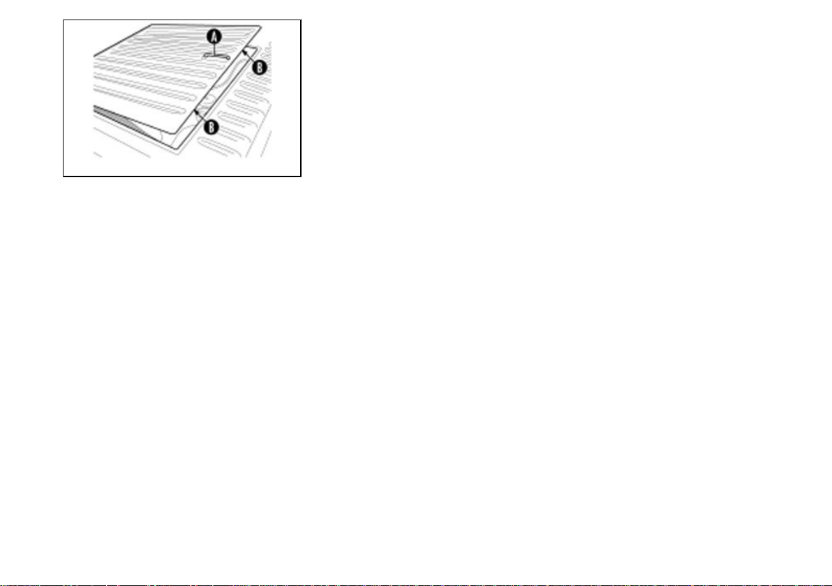
Checking and replacing the pre-heating plugs (13_20)
Access the spark plugs as follows:
1. remove the plate releasing the three fixing clamps;
2. disconnect the high voltage wire cap «A» from the spark plug «B»;
3. remove the spark plug using the provided tool;
4. when refitting, place the spark plug in place at the correct slant and screw it by hand.
Use the tool for locking only;
5. insert cap «A» fully on the spark plug and refit the rear washer.
THE SPARK PLUG SHOULD BE REMOVED ONLY WHEN THE ENGINE IS COLD.
CHANGE THE SPARK PLUG EVERY 4,000 KM. USING SPARK PLUGS WITH
DIFFERENT VALUE WITH RESPECT TO THE PRESCRIPTIONS OR WITH INCORRECT THREADING CAN SEVERELY DAMAGE THE ENGINE.
Characteristic
Recommended spark plugs:
BOSCH W3AC
CHAMPION RL78C
NGK BR8HS
87
Page 88

13_21
13_22
Fuses (13_21, 13_22, 13_23)
The electrical system is protected by six 8A fuses located underneath the instrument
panel, to the left of the steering column.
To the left of the fuse-box are two fuses: 15A fuse «G» protecting the cigarette lighter,
and 15A fuse «I» guarding the heater fan.
Van versions are also fitted with an 8A fuse located underneath the right-hand side
seat and protecting the van lighting circuit.
The vehicle is also protected by the main fuse «H» located underneath the passenger
seat.
The function of general fuse «H» varies according to the version:
- Gasoline = 40 A Safeguarding all services with the exception of the start-up power
circuit.
- Diesel = 40 A Safeguarding the preheating and charging circuits.
Next to the main fuse, on the tipper version, is an additional 80A fuse safeguarding
the body tilting system.
The six 8 A fuses safeguard different circuits depending on the vehicle's version.
BEFORE REPLACING THE BLOWN FUSE, TRY TO ELIMINATE THE FAULT
THAT CAUSED IT TO BLOW. NEVER ATTEMPT TO REPLACE A FUSE USING A
DIFFERENT MATERIAL (I.E. A PIECE OF ELECTRIC WIRE) OR A HIGHER AMP
FUSE.
13_23
88
Page 89

13 Maintenance
IF YOU WANT TO FIT ADDITIONAL UNITS ON THE VEHICLE (E.G. ADDITIONAL
LIGHTS) WE POINT OUT THAT INCORRECT DERIVATIONS ON THE ELECTRIC
CONNECTIONS MAY CAUSE DAMAGE TO THE INSTALLATION.
Handlebar gasoline version
A. Dipped beams (left and right), rear fog light circuit.
B. High beams (left and right), high beams indicator.
C. Emergency (key OFF), windscreen wiper, horn, glass bowl.
D. Emergency (key ON), flashing lights, indicator circuits (recharge, oil reserve, fuel
reserve, tilting), stop lights, reverse gear lights.
E. Instrument lighting, light indicator, number plate lighting, taillights (left rear and
front), cigar lighter lighting.
F. Taillights (right rear and front).
Steering wheel gasoline version
A. Emergency (key OFF), windscreen wiper, horn, glass bowl.
B. Emergency (key ON), flashing lights, indicator circuits (recharge, oil reserve, fuel
reserve, tilting), stop lights, reverse gear lights.
C. Right dipped beam.
D. Left dipped beam, rear fog light circuit.
E. Instrument lighting, light indicator, number plate lighting, taillights (left rear and
front), cigar lighter lighting.
F. Taillights (right rear and front).
89
Page 90

Handlebar diesel version
A. Emergency (key OFF), windscreen wiper, horn, glass bowl.
B. Emergency (key ON), flashing lights, indicator circuits (recharge, oil pressure, oil
temperature, fuel reserve, preheating, tilting), stop lights, reverse gear lights, solenoid
valve, preheating (power circuit excluded).
C. Right dipped beam.
D. Left dipped beam, rear fog light circuit.
E. Instrument lighting, light indicator, number plate lighting, taillights (left rear and
front), cigarette lighter lighting.
F. Taillights (right rear and front).
Handlebar diesel version
A. Dipped beams (left and right), rear fog light circuit.
B. High beams (left and right), high beams indicator.
C. Emergency (key OFF), windscreen wiper, horn, glass bowl.
D. Emergency (key ON), flashing lights, indicator circuits (recharge, oil pressure, oil
temperature, fuel reserve, tilting, preheating), stop lights, reverse gear lights.
E. Instrument lighting, light indicator, number plate lighting, taillights (left rear and
front), cigarette lighter lighting.
F. Taillights (right rear and front).
90
Page 91

13 Maintenance
13_24
13_25
Exhaust circulation system (EGR) (13_24)
Secondary air box - SAS (gasoline version)
Remove the two screws «A» of the aluminium SAS cover, without extracting the metal
pipe from the cover/sleeve. Remove the plastic cover and the plate, pull the sponge
out and wash with soap and water.
Dry with compressed air before reassembling. Reinstall the plate into the seat on the
two plastic and aluminium covers.
Replace the box sealing O-Ring housed in the cover seat at every disassembly.
TURN TO AN AUTHORISED PIAGGIO SERVICE CENTRE FOR THIS OPERATION.
Tyres (13_25)
•
Periodically check the inflation pressure of each tyre.
•
Tyres feature wear indicators; replace tyres as soon as these indicators become visible on the tyre tread.
•
Also check that there are no cuts on the sides of the tyres or irregular tread
wear; in such cases, contact an authorised service centre for the replacement.
Characteristic
TYRES
4.50 - 10''
91
Page 92

TYRE PRESSURE
Front tyre pressure 2.5 atm
Rear tyre pressure 4.5 atm
Pressure
ACCORDING TO THE PROVISIONS OF THE REGULATIONS IN FORCE, THE
TYRE TREADS MUST BE OVER 1.6 MM THICK.
CHECK TYRE PRESSURE WHEN COLD. INCORRECT TYRE INFLATION PRESSURE WILL CAUSE UNEVEN THREAD WEAR AND MAKE DRIVING DANGEROUS.THE TYRE MUST BE REPLACED WHEN THE TREAD REACHES THE WEAR
LIMITS SET FORTH BY LAW.
Periods of inactivity
Prolonged inactivity
If the vehicle is not to be used for long periods, the battery must be charged periodically
(when not in use, the battery will discharge over a period of about three months). If
the battery is removed, make sure you connect the leads correctly at the time of installation
Perform the following operations:
1. Clean the vehicle;
92
Page 93

13 Maintenance
NO START-UP (GASOLINE VERSION)
Connectors to the spark plug
disconnected
DIFFICULTIES WHEN STARTING (GASOLINE
VERSION)
Fuel tank empty Refuel
Clogged or dirty filters, jets or
carburettor
Starter control lever in lowered
position
2. Remove the air filter and close the intake and exhaust ducts;
3. Lift the vehicle from the ground, resting the wheels on wooden supports;
4. Drain the fuel tank. Cover the unpainted metal parts with rustproof grease;
5. For the battery, follow the procedures indicated in the «Maintenance» section.
FOR THE GASOLINE VERSION WITH ENGINE ON AND AT LOW SPEED, POUR
30 CC OF SAE 40 OIL THROUGH THE CARBURETTOR CHOKE.
Restore connection
Contact an Authorised PIAGGIO
Service Centre
Move it to lifted position
93
Page 94

DIFFICULTIES WHEN STARTING (DIESEL VERSION)
Connectors to the glow plug
disconnected, or inefficient glow
plug
No fuel in tank Refuel
Air into the injection system Bleed the air
Water in the diesel Drain the water and replace the
Injector dirty or faulty Contact an Authorised PIAGGIO
Restore the connection or replace
the preheating glow plug
filter, if required, then bleed the air
Service Centre
IGNITION FAILURE (GASOLINE VERSION)
No spark on spark plug Check whether the electrodes are
clean (clean with white spirit and
wire brush or sandpaper).
Check spark plug insulation: if
cracked or broken, replace the
spark plug. If the spark plug is in
good conditions, contact an
Authorised PIAGGIO Service
Centre.
CAUSE: HIGH VOLTAGE. THIS INSPECTION SHOULD BE
CARRIED OUT BY A SKILLED MECHANIC.
94
Page 95

POOR COMPRESSION (GASOLINE VERSION)
13 Maintenance
Spark plug seat threading
damaged; head bolts insufficiently
torqued, piston seals worn
Contact an Authorised PIAGGIO
Service Centre
HIGH FUEL CONSUMPTION AND POOR
PERFORMANCE (GASOLINE VERSION)
Air filter blocked or dirty Replace the air filter
ENGINE IRREGULAR OPERATION (DIESEL VERSION)
Injector faulty Contact an Authorised PIAGGIO
Air into the injection system Bleed the air
Diesel filter clogged Replace the filter and bleed the air
Service Centre
POOR PERFORMANCE (DIESEL VERSION)
Injector faulty Contact an Authorised PIAGGIO
Diesel filter clogged Replace the filter and bleed the air
Service Centre
95
Page 96

WHITE FUMES UPON EXHAUST (DIESEL VERSION)
Injector faulty Contact an Authorised PIAGGIO
Delayed injection Contact an Authorised PIAGGIO
Service Centre
Service Centre
BLACK FUMES UPON EXHAUST (DIESEL VERSION)
Air filter clogged Replace the air filter
Wrong injection pump calibration Contact an Authorised PIAGGIO
Injector faulty Contact an Authorised PIAGGIO
Service Centre
Service Centre
THE ENGINE KNOCKS
Injection advanced Contact an Authorised PIAGGIO
Injector faulty Contact an Authorised PIAGGIO
Service Centre
Service Centre
96
Page 97

POOR SUSPENSION
13 Maintenance
Oil leaks or inadequate spring
loading; stroke end bumpers worn.
Contact an Authorised PIAGGIO
Service Centre
TRANSMISSION IS NOT SMOOTH
Gearbox failure Contact an Authorised PIAGGIO
Gearcase noise Contact an Authorised PIAGGIO
Service Centre
Service Centre
POOR BRAKING ACTION
Drums greasy, brake shoes worn Contact an Authorised PIAGGIO
Air into the circuit pipes Bleed the air
Shoe self-adjustment device faulty Contact an Authorised PIAGGIO
Irregular friction material wear Contact an Authorised PIAGGIO
Oil leaks from the circuit Contact an Authorised PIAGGIO
Air in the brake circuit Bleed the air Contact an
Service Centre
Service Centre
Service Centre
Service Centre
authorised PIAGGIO service
centre.
97
Page 98

ELECTRIC SYSTEM INEFFICIENCY
Faulty controls (switches) or lights
and indicators
Battery inefficient Contact an Authorised PIAGGIO
Contact an Authorised PIAGGIO
Service Centre
Service Centre
Troubleshooting / What to do if... (13_26)
Idle adjustment
Adjust the idle speed as follows:
1. Release the three clamps and remove the plate.
2. Start the engine and take it to its normal operating temperature, i.e., 5 minutes run
at a medium speed.
3. Turn the gas valve travel end adjustment knob «A» to approach the minimum stop
13_26
limit of engine spontaneous stop.
4. Then, adjust the mixture flow adjustment screw «B» to reach the highest rpm number. If the rpm number reached is excessive, decrease it by knob «A» to reach a
regular minimum speed.
If this is problematic, go to a PIAGGIO Dealer or Authorised Service Centre.
THE IDLE ADJUSTMENT MUST BE PERFORMED WITH HOT ENGINE AND ACTIVE CATALYTIC CONVERTER. BEFORE PROCEEDING, CHECK THAT THERE
IS NO PLAY ON THE THROTTLE CONTROL. IF REQUIRED, GO TO A PIAGGIO
DEALER OR AUTHORISED SERVICE CENTRE TO HAVE THE THROTTLE CONTROL PLAY ADJUSTED.
98
Page 99

13 Maintenance
CAUTION
IN CASE OF PROBLEMS WHEN ADJUSTING THE IDLE SPEED, IT MAY BE NEC-
ESSARY TO ADJUST EXHAUST EMISSIONS (CO). THIS OPERATION MUST BE
PERFORMED AT AN AUTHORISED PIAGGIO SERVICE CENTRE.
Characteristic
Idle adjustment
(approx. 1250 - 1450 rpm)
Troubleshooting / What to do if... (13_26, 13_27)
Brakes adjustment
The brake shoes are provided with a self-adjustment device that automatically restores the proper clearance between blocks and drums, regardless of the friction
material wear, so it is not necessary to perform manual adjustments.
The brake drums are provided with hole with screw cap «A» through which it is possible to inspect the wear of the friction material: In case of excessive wear, replace
the brake shoes. For this operation, turn to a Concessionaire or to an Authorised
PIAGGIO Service Centre.
13_27
Troubleshooting / What to do if... (13_27, 13_28)
Parking brake
Pull the lever to engage parking brake. Lift the lever slightly to release the brake, press
the button with the thumb and lower the lever completely.
13_28
•
BEFORE SETTING OFF ENSURE THE PARKING BRAKE IS FULLY RELEASED AND THE WARNING LIGHT IS OFF. SHOULD THE PARKING
BRAKE BE PARTIALLY PULLED, THIS WOULD CAUSE THE BRAKES
99
Page 100

13_29
TO OVERHEAT RESULTING IN LOSS OF BRAKING EFFICIENCY AND
EARLY WEAR OF THE FRICTION MATERIAL.
WHEN PARKING THE VEHICLE ON HILL ROADS, ALWAYS PULL THE PARKING
BRAKE LEVER FULLY AND MOVE INTO THE LOWEST GEAR OPPOSITE THE
DIRECTION FACED BY THE VEHICLE. IN ADDITION, POSITION WEDGES BEHIND THE WHEELS.
•
TO IMPROVE SAFETY AND AVOID ACCIDENTAL ACTIVATIONS, WE
SUGGEST YOU ALWAYS PULL THE PARKING BRAKE BEFORE, OPERATING THE LIFTING/LOWERING BODY CONTROL.
Troubleshooting / What to do if... (13_28, 13_29)
Air bleeding from the braking system
In case of anomalies of the brake performance, accompanied by idle pumping, have
the system drained by the Concessionaires or Authorised PIAGGIO Service Cen-
tres.
IN FACT, THE BRAKE FLUID IS HIGHLY CORROSIVE AND IT MUST BE DIS-
POSED ACCORDING TO PRECISE REGULATIONS. MOREOVER, ANY INTERVENTION TO THE BRAKING SYSTEM MUST BE CARRIED OUT ONLY BY
QUALIFIED PERSONNEL.
100
 Loading...