

Page 1

OPERATING
INSTRUCTIONS
AND
PARTS
LIST
FOR
MOTOR SCOOTER
r------
MODEL NUMBER 788.94331
This is
the
Model
Numberofyour
Allstate
Motor
Scooter.
It will
be
found
onaplate
fastenedtothe
chassis
under
the
fuel
cock.
Always
mention
this
number
when
communicating
with
us
regarding
the
Scooter,orwhen
ordering
repair
parts.
r-----
HOW TO ORDER REPAIR PARTS
All
parts
listed
herein
may
be
ordered
through
any
Sears
retail
or
mail
order
store. In
ordering
parts
by
mail
from
the
mail
order
store
which
selVes
the
territory
in
which
you
live, Selling
Prices
will
be
furnished
on
request
or
parts
will
be
shipped
at
prevailing
prices
and
you
willbebilled
accordingly.
WHEN
ORDERING REPAIR PARTS, ALWAYS GIVE
THE
FOLLOWING INFORMATION:
1.
The
Part
Numberinthis List.
2.
The
Part
Nameinthis List.
3.
The
Model
Numberofthe
item.
This list is valuable. It will
assure
your
being
able
to
obtain
proper
parts
service
at
all
times.
We
suggest
you
keep
it
with
other
valuable
papers.
SEARS, ROEBUCK
AND
CO.
Scooterworks USA Inc.
5709
N.
Ravenswood
Chicago,IL60660
ph: 773.271.4242
fx:
773.271.5012
Page 2

Page 3

Fig. 1 .
AUST"TE•
Crui.aira•Motor
xoot.r
WARNING
lO<ltlon
of
fnm.
Number
lo<ationof."9in.
Number
Fig. 2 •
lO<ltlonof..
rill
number
Serill
numbers
are
preceded
by
pretixM:
V A1~T,
for
frame;
VNB 5 M, for
1"9;n
•.
In
order
to keep
your
ALLSTATE
Scooterinperfect
running
condition
and
nottovoid
the
guarantee,
always
have
your
machine
repaired
at a Sears, Roebuck
and
Co. Store.
Special care
shouldbetaken
with
regardtothe
fuel
mixture
which
should
be
regular
gasoline
and
oil
of
the
make,
grade
and
in
the
amount
prescribed
in this
booklet.
Ethyl
~asoline
should
never
be used.
Do
not
use
Allstate
compounded
motor
oilorother
Praemium
Huvy
Duty
Oil
with
detergents.
The
inexperienced
operator
should
exercise
caution
in
applying
front
wheel
brake,
to
avoid
locking.
C\-
\
'lg.
3 •
Control.of"Ilstat.
xoot.r
1.
Gear
chenge
twistgriO
with
clutch control
lever·2.Front
brake
lever·
3. Throttle con-
trol
grip.•.
light
and
dimmer
,witch
.
S.
Front
brake
iaws
..6.Rear
brake
pedal.
7.
Kickstarter
.•.
Gear
,hi
Iter
. 9. Rear
brake
iaws.•10.
Clutch.11.
Carburettor,
air
cleaner.
12.
Starter
push
pull
rod·
13.
F"el
cock.
Page 4

";.
4 • l"9In.
Inltallatlon
and
....
p4n.I.M.
1
r--------/-I
6
Ignition.•By
flywheel
magneto.
Engin.
to
wheel
trensmission
retios:
First 13.35 0 1
Second
9.32
to
1
Third
6.64
0 1
Fourth 4.85
to
1
fit. 5 • 1
..
1ti_
ojl
......
1.
Ignillon
coli in
flywh_1
mlQn.«>
··2.
Rolor
~m
•J.Brea
.....~.Con-
danlO".5.
Sparlcplvg .,.Engin.
cvl·
""eon.wilch.
Clutch..Wet
type;
multiplate,
with
facingsofcod
..
composition
applied
to
the
driving
discs.
Geer
box..4 -
speed
drive
with
mesh
gears
in
od
bath.
Its
two-<able
controliscoupled
with
that
of~e
clutch,
on
left
hand
side
of
handlebars.
123.4 cc.
(7.53
cu.
in.)
52.5
mm.
(2.06
in.)
57
mm.
(2.24
in.)
4.6
HP
7 : 1
5000
rpm
MAIN
SPECIFICATIONS
Trtlnlmlulon.
Oi
re<:tly
from
engine
to
rearwheel
gh
clutch,
cushion
drive
and
gear
box.
SYrtlng
..
By
means
of
kickstlHter,
right
hand
side
SCooter.
1.
~
c.olvmn
and
Irone
svspension
. 2. Engln
...J.Cranlcc
....
half,
c1vtch
sid.,
wilh
swinging
arm.4.
Raar
svspension
spring
with
hy-
dravlic
damper.
IIv.f
eonsumption:
1M.
oil
milcture)
130
miles
per
gal.
'P"d
.
46.6
m.p.h.
bue .
46.4
in.
wldttt
on
hendlebus
25.7 in.
~;tn
of
the
scooter
68 in.
~Ight.
. . . . 38.7 in.
~Ight
of.
·f1oorboud
8 in.
drcl.
59 in.
(
un'ed.n)
. 182 Ibs.
~.m
•..
Of
pressed
and
spot-welded
steel
sheet,
th
Itreem-lined
monocoque-type
structure.
M~nslon
.•
Front
wheel:
coil
spring.
Rear
wheel:
I9
rin
g
and
coaxial
hydraulic
shock
absorber.
L,gln
•..
Two·
stroke,
flat
cast
iron
cylinder
and
Iluminium
alloy
cylinder
head.
Cooling
effected
by
rifugal fan w ichisembodied
in
the
flywheel
of
tn4Igneto.
lacement
-4-
Page 5

lubrication.
- By the
oilinfuel
mixture
for
piston,
cylinder,
wrist
pin,
con. rod, cranks
aft,
main
bea-
rings.
Both clutch
and
gear
box
operate
in oil
bath.
Carburettor.-With
float-cham-
ber
(see
fig.11);
air cleaner
moun-
ted on the
engine.
Air
goes to the
carburettor
through
a
large
inlet
tube
and a silencing
chamber
with
filter.
Modelofcarburettor:
Dell'Or-
to
51
20/15
C -
Venturi
15
mm.
(0".59)
-
Main
jet
82/100
(0".
0323)
-Idler
iet
42/100
(0".0163)
-
Air-vent
for
main
jet
120/100
(0".0473)-Air
holeonmixer
top
150/100
(0".05)-Mixer
tipe
BE
1.
-
Air-vent
to
idler
jet
140/100
(0"
.055)
- Spray nozzle
200/100
(0"
.0788)
-
Sta
rter
jet
55/100
(0".0216)
- Float
chamber
fuel le-
vel
20.5 ± 1
mm.
(0"
.87)-Oil
recovery
vent
50/100
(0".0197).
Feeding. - Fuel
feed
to the
carburettor
is
pr.ovided
for
by
gravity
(see
fig.
11)
with
gasoline-oil
mixture.
Fuel
tank.
- Total
capacity:
2,03
gals.;
Reserve:
V1
1/3
gal.;
Three-way
cock:
«open»
. «
closed»
- « reserve
».
Mumer.-Expansion
and
absorption
combined
type.
Handleb.rs
..
Pressure
die
cast in
light
alloy
and
designed
so
as
to house
both
headlamp
and
speedo-
meter.
All
the
control
cables
and
electrical
wi
res to
this
group
are concealed
therein.
(See
fig.
3).
Steering
column..The
steering
column
bears the
handlbears,
clamped
on its
top
end,
and
the
front
wheel
swinging
hub,
pivoted
at its
bottom
end
throughastub
axle.
lighting
.nd
hom.
- By
flywheel
magneto,
feeding
both
head
lamp
(two-beam),
tail
lamp,
horn
and stop
light
(see
fig.
9).
Brakes. -
Expanding
type.
Front
brake:
control
lever
on
right
hand
side
of
handlebars.
Rear
brake:
control
pedal
on
right
hand
side
of
floorboard.
The rear
brake
jaws
are
hinged
on
indepen-
dent
pivots.
Wheels. -
Of
pressed steel sheet,
interchangeable
and
easily
removable,
since
they
are
assembledinan
auto-
mobile-like
system.
Tires:
dia.
3.50
x 8
in.
Steering
lock..A
suitable
security
lockisarranged
on the
frame,
near
the
handlebars.
Turning
the
key
counter-clockwise
and
the
handlebars
to
the
left,
the
lock engages
the
lugs
welded
on
the
steering
column,
so that the
machine
can
only
turn
around.
Turn the
key
clockwise
and
the
handlebars
back
to
normal
position
for
releasing
the
steering
system
(see
Fig.
7).
Do
not
Fig. 6 •
Sealon0/engine
1. Air
cleaner
and
carbvrettor
. 2..Piston·
3.
Cranksnaft-4.
Clutcn
S.
Mainsnaft
. 6.
Gear
snifter.
7.
Fliywneel
magneto·
•.
Kid
starter
9.
Crankcase
n.lf.
clutcn
side.
witn
swinging
arm.
attempt
to
ride
the
machine
unless
the
keyisin,
and
re-
mainsinthe
lock,
and
the
handlebars
are
moving
freely.
Do
not
lubricate
the
steering
lock.
Security
lock
on
tool
box
wing.
- The
compartment
flap
on the
left
wing
of
the
vehicle
is
equiped
with
a
key
operated
security
lock.
Centr.1 Stan. - A
two-legged
standisarranged
un-
der
the
floorboard.
A
strong
return
spring
holds
it in
~.
7 -
s.cvrity
Io«k
1. Norm.1
position.
2.
Closed
- 5 -
Page 6

'IV·
• -
Spar.
wh
••
1
and
buck.t
...
...
,
\
\
\
I
I
I
I
"
~
//
-~~---
\/
",
10
5
,-------------------
..
"'Tt---------..
--~!:O~~~__+_---.(O
------+-+-----+r"'"
Tool Kit. - 1
four-ended
box
wrench
(11
- 14 -
21
22
m);1double
open-enQed
wrench
(8
- 14
mm);
1
single
open·
ended
wrench
(7
mm);
1
screw-driver.
These
hand
tools
are
containedina roll
whichisplaced
in
the
left
wing.
Speedometer.-The
speedometer
has
its
housing
in
the
middle
of
the
handlebars
and
adds
to
the
perfor-
mance
and
appearance
of
the
scooter.
Accessories
(See
Table
XX).-On
request
the
Allstate
scooter
can
be
equipped
with
the
spare
wheel
and
bracket.
A
FiV.
9 -
Schem.
of
EIKtTic Wlri"",
contact
witt'e
oorboard
and
keepsitfrom
:ibrating
wnile
the
scooterisbeing
ridden.
Spare
wheel
.nd
br.cket
(see
fig.
8).
- The
wheel
bracket
sheet
steel
pressing,
canbesecuredtothe
scooter
frame
behind
luggage
carrier
(see
Table
XX,
«Spare
parts
list»).
_
Itisvery
robust
and
simple
and
holds
the
wheel
in
such a
position
whereitis
easily
accessible.
1.
Flywh~~1
m~n~to
-2.low
t~nsion
t~rminal
1.
STOP
li~ht
(6
V . 3 w
bulb)
-4.Toil
lamp
(6
V . 3 w
bulb)
- S.
Spar"plu~
-6.STOP
switch
.7.light
and
dimm~r
switch
-a.6V·22/22
W
doubl~
r.lam~nl
bulb-9.
Horn.10.
Insid~
vi~w
of
heed
lamp.A:
Engin~
cuI·
out:
B:
li~hls
off
.
c:
H~ad
lamp
and
toil
lampon.
0:
L~v~r
for
country
and
lrafioc
beam.E:
Horn
button.
Page 7

OPERATION
IF
THE
SPEEDOMETER
(WITH
MilE
DIAL)
HAS
BEEN
DISMANTlED,
FOR
REASSEMBliNG
PROCEED
AS
FOllOWS:
(See
fig.
10)
Filii.
10·
How
10
aU41mble
the
Ip
..
dome4er
unit
lodged
in
the
square
cut·
out
of
the
speedo.
drive
pinion.
Make
sure
that
the
end
of
the
flex
drive
enters
the
square
section
hole
of
the
speedometer
drive
pinion.
Rotate
the
wheel
by
hand
for
several
timesinorder
to
make
sure
thatitturns
freely.
Grease
pinion
c I
~
.
support
bush
c L
~
assy
through
lubricator
on
ring
c K
~.
Duetothe
simple
and
conventional
design
of
the
Allstate
scooter,
no
particular
skill
is
required
for
its
operation,
nor
skilled
personnel
for
its
maintenance.
The tasks can be
quite
well
carried
out
by
.,ny
customer,
even
inexperienced,
by
carefully
following
some
general
rules.
Running-
in.-Important
rulestobe
followed
while
running.
in
(1200
miles)
:
Do
not
exceed
following
speeds:
1st
gear
13
mph.
2nd
gear
19
mph.
3rd ge1H
25
mph.
4th
gear
37
mph.
Do
not
hold
these
max
speeds
for
long
periods
neither
use
full
throttle
opening
up-hill.
Change
oil
in
the
gear
box
and
check
thl!lt
nuts
and
bolts
are
not
slack
after
the
first
600
miles.
to
flow
out;
otherwise
top
up
with
ALLSTATE REGULAR
S.A.E.
30.
With
the
help
of.,pilot
wire
slide
the sheath c A
~
for
the
flex
drive,
into
the
steering
column,
from
the
top
end,
untilitemerges
from
the
bottom
end
(indicated
with
an
arrowinthe
figure).
Pull
the
pilot
wire
outofthe sheath,
grease
the
flex
drive
generously
and
slide it
in.
Assemble
packing
c C
~
and
then
the
speedometer
head
c B
~
on the
bracketE,already
mounted
with
rubber
buffer
c F
~
fixing
with
the
apposite
screw
c U
~
and
spring
washer
c T
~
ensuring
that
said
screwisnot
tightened
too
firmlytoavoid
deformation
of
the
speedometer
head.
Insert
the
upper
end
of
the
flex
drive
into
housing
in
the
speedometer
head
and
secure
both
flex
drive
and
sheath
by
meansofknurled
ring
nut
c G
~.
Now
secure the
group
speedometer
and
bracket
to
the
handlebars
by
means
of
the
screw
c S
~
and
plain
washer
c R
~.
Completed
the
above
operations
reassemble
the
head·
lamp.
Fill
up
hub
with
grease in
order
to
lubricate
the
portion
of
the
wheel
spindle
meshing
with
the
spee-
dometer
drive
pinion
c I
~.
Mate
the
pinion
c I
~
to the
support
bush
c L
~,
then
mount
ring
(with
lubricator)
c K
~
on
the
latter;
screw
the
support
bush
c L
~
on
the
wheel
hub.Ifan
axial
play
between
drive
pinion
and
centre
pin
of
0.25to0.8
mm.
(0".01
to
0".03)
is
not
obtained
on
assembling
the
part
c L
~
into
the
hub,
interpose
the
spacer
washer
c M
~.
Slide
the
rubber
cap c N~,the
threaded
ring
c 0
~
and
biconical
ring
c P
~
over
the
sheath
end;
fit
the
washer
c Q
~
on
the
cable
portion
which
protrudes
from
the
sheath, P.,ss
the
I.,tter
between
the
front
brake
control
cable
.,nd
the
wheel,
then
screw
and
tighten
threaded
ring
c 0
~
on
bush
c L
~
and
po-
sition
rubber
cap c N
~.
Ensure
that
the
end
of
the
flex
drive
is
accurately
-1-
Keep
the
breather
of
filling
cap
clean.
Fuel
$upply..Fuel
mixture,
both
during
and
after
running
in,
should
be
composed
of
regular
gasoline
and
pure
mineral
oil
SAE
30at2%,i.e.:
-
If.I.
pint
of
oil
1%
gallons
of
gasoline.
When
using
pre-diluted
or
additive
oils,oroils
for
outboard
motors,
mix
1,4
pint
of
oil
per
gal.
Oil
level.
- Remove
the
level
screw,
on
crankcase,
markedcOLIO~as
indicated
on
page
11
Fig.
20,
to
check
oil
level
in
gear
box
before
starting
the
engine.
The
scooter
standing
upright,
oil
should
just
be
about
Page 8

----
Stlrtinlil·.Open
:ne
fuel
valve,
put
the
gear",
box
in
neutral
and
slightly
open
the
throttle
in
slow
running
position,
kick
the
starting
lever.
With
cold
engine,
operate
starter
push
pull
rod.
Push
said
rod
backassoonasthe
engine
fires.
See
Fig.11;
note
the
three
positionsofthe
fuel
valve:
open,
closed,
reserve.
C.ution
..
Do
not
open
throttle
wide
when
releasing
clutch.
In
case
of
starting
troubles,
due
to
engine
being
flooded
(unvaporized
fuel
mixture
has
reached
the
cy.
linder
and
combustion
becomes
therefore
very
difficult),
proceed
accordingtoeither
oneofthe
following
methods:
a)
Push·
start
the
scooter:
shift
into
second
gear,
declu
ch
and
push
the
machine;
quickly
release
the
clutch
lever
and
pullitbackassoonasthe
engine
starts.
b)
Close
the
fuel
cock,
remove
the
spark
plug
and
rotate
the
engine
by
means
of
the
kickstarter.
Wipe
the
plug
dry
and
replace.
Open
the
fuel
cock
and
kick
the
starting
lever.
FiQ.11.
Feeding
circuit
1. Fuel
cock
lever:
A)
Reserve.
B J
Open.C)Closed·2.Floal .J.Air
eleaner
and
carburellor.J/l.
Air
filler
.•.
Slaner
iel.5.
Sel
screw
for
lhrollie
slide·6.ThrOllle
slide·
7. Air
venl
for
main
jel .a.Hole
on
mixer
top·
9.
Mixer·
10.
Main
jel.11.
Idling
let.
12.
Air
venl
for
idling
iel.1J.
Plug for
inlet
hole
for
oil:
for
layingup. 1•.Idling
adju'ter.15.
Slaner
valve·
16.
Intake
port·
17.
Tran,fer
pon,
.
11.
ExhauH
duct.
FiQ.
1::l•Opentlon.
to
clrry
out
I.,
ttlrtl"9
tho
e"9;n.
"':
open
lhe
fuel cock .B:'electcneulral•.C:
operlle
'larter
push
pull
rod
(with
cold'
engine).0:
lhrollie
conlrol
gripinidling
po,ition.E:
deprell
the
kick'larter
and
turn
grip•O.
by
,hort
'lroke,.
- 8 -
Page 9

1
:1
I
i
i
For
acceutothe
engin.,
take
off
the
engine
cowlin~
then
proceed
as
follows.
Pull the
lever
« 1
~
(Fig.
13)
and
turnitso
as
to
release
it
from
bonnet.
Then
move
the
bonnet
slightly
outwards,
until
front
pivott(2~is
extracted
from
the
hole
on
the
frame.
Push the
bonnet
from
the
front
upwards
and
turn
it
(see
position
indicatedbydotted
line),
thus releasing
the
fixing
hook
« 3
~
from
frame.
Move
bonnet
outwards
round
its
hooked
pivot
« 4
~
until
the
latter
disengages
from
the
hole
on
frame.
Thus the
bonnetisremoved.
Forre-
assembly,
follow
the
reverse
procedure.
Setting
the
machineinmotion.-Let
the
engine
idle,
depress the
clutch
and
turn
the
gear
change
twistgrip
so
that the
line
engraved
onitcoincides
with
the
figure
«1~(1st
gear)
engraved
on
handlebars
(see
Fig.
14).
Now
letinthe
clutch
gently,
while
opening
the
throttle
gradually
to set
the
machineinmotion.
Gear
change.-On
attaining
the
required
speed in
1
st
gear,
quickly
close
the
throttle,
release the
clutch
and
turn
the
gear
change
twistgrip
so
that
the
engraved
line
coincides
with
figure
« 2
~
(2nd
gear);
let in
the
clutch
and
open
the
throttle.
FJ9.
13
•
(nvI-
bonnet
,..
....
0
...
1
1.
EnQine
bonnet
locking
lever.2.
Front
pivot•3.
Fixing
hook
•
4.
Hooked
pivot
Repeat
this
procedure
for
changing
into
3rd
and
4th
gear
and
for
changing
down.
See the
drive
system
on
Fig. 14.
When
you
reduce
the
speedofyour
machine,
change
down
without
delary
to
avoid
irregular
engine
running
and
stallingatlow
revs.
"9.1•.
Od".
"y"t.m
1.
Gear
change
twistgrip.2.
Clutch
control
lever.3.
Gear
chan9"
control
c.ble.-•.
Gear
.hifter•5.
Sele<tor
stem·
6.
Selector·
7.1st
gear·•.2nd
gear-,.
3rd
gear·
10.
4th
gear·
11.
Mainshaft_12.
Cush
gear.13.
Clutch.
N.II..
Positions
1·2
- 3-.of
the
gelr
ch.nge
twi.tgrip
correspond
to
1st.
2nd.
3rd
.nd
4th
gear
respectively;
«0.
indicales
the
n~utr.1
position.
Do
not
turn
the
gear
change
twistgrip
while
the
engineisnot
running.
As soon
as
gear
change
troubles
arise,
particularly
when
the
control
becomes
hard,
customers
should
have
their
machines
adjusted
by
a Sears
Store.
Slow
running
adjustment••No
hand
toolisrequir.
ed
for
this
job.
Idling
revs can be
raised
or
reduced
respectively
by
simply
tightening
or
slackening
the
knurled
slotted
screw
on
air
cleaner
steel
sheet
cover
(No.5,
Fig.
11).
This
screw
controls
the
throttle
slide
valve.
The
adjuster
screw
for
the
throttle
control
cable
is
installed
on
the
air
cleaner
case. This
screw
is
to be
reset
only
when
necessary
and
while
dismantling
and
re •
assembling.
Opposite
to
said
adjuster
screw
there
is
on
the
air
cleaner
case a
plugged
hole
for
access
to
another
screw
(spring
loaded);
see Fig.
11
No.
14.
This
screw
controls
the
flow
of
carburated
air
through
the
duct
from
the
idling
jet,
and
consequently
the
idling
revs.
We
recommend
that
customers
refrain
from
re-
setting
this
screw
unless
absolutely
necessary
or
during
-9-
Page 10

:'
FiV·
15 . Olsmlntlir>g
th.
frontwh••
1.
dismantling
and
re -
assembling
operations
that
should.
anyway,
be
entrusted
to a
Sears
Store.
Stopping
the
engine
..
Push
the
earthing
button.
This will
leave
the
cylinder
fulloffuel
vapours,
and
the
next
start
will be
much
easier.
Tires. - The
wheels
are
interchangeable,
i.e.they
can
be
assembled
either
in
front
or
rear,
provided
of
course
that
they
are
inflated
to
pressures
respectively
hereunder
prescribed.
When
a flat tireisto
be
replaced,
unscrew
the
four
nuts
which
secure
the
wheel
to
its
flange,
pull
wheel
sideways
off
the
studs
(see
Fig.
15),
repairitor
replace
with
spare
wheel.
To
remove
the
tube,
first
deflate,
then
separate
the
felloe
from
the
ring
by
unscrewing
the
nuts
which
join
them
(see
Fig.
16).
Av·
16.h",o.ir>g
Ik.
Inno,
IUbo
Tire
pressure
should
be
18
-;.20psi
on
rear
wh~
14
.'c- 15,.5
psi
on
front
wheel.Ift e
AllstateISordi
aril
ridden
by
both
driver
and
passenger.
he
pressure
c
he
re,H
tire
should
be
28.5
-;.
31
psi.
®
F1V·17.
8,.lto
Idjurtmont
Br.ke
.djustment.-Brakes
are
properly
adjus
ed
if:
the
wheel
rotates
freely
when
respective
control
le-
ver
or
pe~t
ire
in
resting
position;
the
braking
action
starts
as
soon
as
respective
con-
trols
are
operated.
These
conditions
are
achieved
adjusting
the
cables
by
means
of
screws
indicllted
with
an
arrow
in Fig. 17.
a
F19.
1••Adjustmontofclut.:h
control
.)
Adjusting
nut•b)
Clutch
lever.
eng,ne
.ide
- 10 -
Page 11

MAINTENANCE
I
i
~
Adiustment
of
clutch
control..Adlustment
of
clutch
controls
is
achieved
operating
on
adjusting
nut
(a),
screwed
to
the
engine
bracket
(see
Fig.
18),
by
means
of
open
ended
wrench
82199
in
the
tool roll.
The
cable
is
to
be
tensioned
or
loosened,
as
the
Cleaning
the
scooter.-Brushing
kerosene
and
wi·
ping
dry
clean
rags
is
advisable
for
external
cleaning
of
engine.
All
painted
surfaces
should
be
washed
with
water,
rinsed
by
means
ofasponge
and
wiped
dry
with
a
chamois.
Do
not
use
kerosene
on
such
surfaces,
since
it
damages
paint
and
turnsitdull
..
If
necessary,
blow
the
head
lamp
reflector
clean
or
wipe
off
dust
withavery
soft
feather.
Do
not
use
a
cloth
and
keep
your
fingers
off
reflector
surface.
Before
setting
the
machineinmotion,
(ifithas
been
delivered
directly
to
the
customer
by
the
Factory)
check
oil
level
in
gear
box
by
unscrewing
the
level
screw
marked"
OLIO,.
from
the
cranckase
(see
Fig.
21
).
The
scooter
standing
upright,
oil
should
just
be
about
to
flow
out.
After
the
fint
600
miles.-Replace
oil in
the
gear
box
by
the
procedure
as
explained
in
the
lubrication
chart,
page
13.
The
crankcase
can
be
drained
through
the
hole
indicated
in Fig. 21.
Every
2.500
miles:
(1)-
Remove
air
cleaner
cover
and
unscrew
the
two
filter
retainer
screws.
Extract
the
filter
(n.
3/1
fig.
11
)
from
carburettor,
w~sh
in
gasoline
and
if
possible
air
blast
dry.
(2)
Check
oil
level
in
the
gear
box
(see
above).
(3)
Grease
all
joints
on
the
brake
controls.
(4)
Clean
the
sparkplug
electrodes
with
very
fine
emery
cloth
or
suitable
files,
and
adjust
the
gap
to
0.6
mm.
(0.023").
Inspect
the
insulation
material
of
sparkplug;
re-
place
the
latterifthe
porcelain
is
cracked.
Wash
with
neat
gasoline.
Use
the
sparkplug
type
Marelli
CW
230
A-
T;
Marell;
CW
225
N -T;Bosch W
225
T 1 ;
Champion
L
86;
AC
43
F;
KLG
F 70orF
75.
Important:
using
the
proper
type
of
sparkplug
will
eliminate
many
engine
troubles.
(5)-Grease
the
felt
which
lubricates
the
cam
of
fly-
wheel
magneto.
(6)-Clean
the
two
lubricators
on
front
wheel
hub
and
refil
them
by
means
ofagrease
gun.
N. B.•All
operations
indicated
hereunder
should
1M
carned
out
by
a SEARS
store.
case
m~y
besothat
control
lever,
on
h~ndlebMs,
makes
a
strokeof2
mm.
(0.078")
before
lever
(b),
on
engine
starts
moving.
Wrong
play
in
the
control
may
cause
the
clutch
plates
burning
out
even
in
normal
running
conditions.
(7)
-
Lubricate
the
speedometer
drive
pinion
and
flex
drive.
(8)
-
Clean
the
muffler
and
decarbonize
the
engine
as
explained
hereunder.
Remove
the
muffler,
the
cooling
hood,
the
cylinder
head
and
the
cylinder
(see
Fig.
20).
Decarbonize
the
piston
crown
and
the
cylinder
ports
from
all
carbon
deposits.
Decar.
bonize
the
inner
side
of
the
cylinder
head.
Care.
fully
clear
the
cylinder
carbon
deposits.
Heat
the
exhaust
pipe
of
the
muffler
and
clean
it
either
by
scraping
internally
withahooked
wire
or
blowing
air
through
from
the
other
orifKe;
in
both
cases
the
muffler
should
be
held
so
that
the
exhaust
pipe
is
turned
downwards.
'i9.19.
Bruhr
points
..
) Max.
gapofbr.a'.r
points
cA.
should
~
0.0
II"
. 0
019"
In
case
of
shock·
absorber
troubles,
overhaul
or
simply
clean
the
assembly
and
changeoiI.
These
operations
should
be
carried
out
by
your
SEARS
store.
Page 12

(1)
.
Every .5.000
mil..:
Clean
the
breaker
points.
In
order
to
avoid
ignition
troubles
or
abnormal
running,
have
the
breaker
points
adjusted
in a
Sears
stores;
the
gap
should
not
be
more
than
0.011"
. 0.019"
(see
Fig. 19)
and
the
points
should
begin
to
open
when
the
current
in the
primary
ignition
circuit
has
attained
its
peak
value.
(2)
Grease
the
control
cables.
(3)
Change
the
oil
in the
gear
box,
as
stated
on
page
13.
(4)
.
Grease
the ratchet
quadrant
of
the
gear
shifter.
Disuse:
(
1)
In such a case,
cleaning
the
scooter
throughly
is
advisable.
(2)-With
engine
not
running
and
with
throttle
control
twistgrip
completely
rotated,
(full
throttle
opening)
pump
40
cc.
of
Allst.te.
Regulu
Oil
SAE
30
or
AlIst.te
Outboud
Motor
Oil
through
hole
in the
air
cleaner
cover
into
the
carburettor
intake,
by
means
of
an
oiler.
Then
operate
the
kickstarter
three
of
four
times.
(3)
Rest
the
floorboard
on
two
wooden
blocksinorder
to
take
the
weight
off
the
tyres.
(4)
Drain
all
fuel
from
both
tank
and
carburettor.
(5)
Grease
all
unpainted
metal
parts.
-
12
-
Fill·20.Cl..
ninq
the
cyllnd.,
hNd,
cyllnd.,
and
pinon
Page 13

LUBRICATION
CHART
PoUTTOBE
O'ElATION
I
TIM
E
I
THE
OF
lUB_ICANT
lUBlllCA
TED
i
I
I
Mix
gasoline
with
the
following
amount
t
At
each
refillingofthe
fuel
i
Pure
mineral
oil
SAE
30.
Engine
I
of
lubricating
oil:
tank.
I
-
~~
pintofoil
to/Vz
gallonsofgasoline.
I
I
N.B.-
With
pre-dilutedoradditive
oils,
!
mix~~pintofoil to each
gallon
I
of
gasoline.
I
Gear Box
Warm
up
the
engine
and
drain
off
oil.
I
After
the first
600
miles
I
Allsta e
Regular
SAE
30.
I
Pour some fresh
oil
in and run the en-
and
every
5000
miles.
I
I
gine
forafew
seconds. Flush and
refil
I
I
with
new
oil
(about7oz.).
I
Refill
with
new
oil
to
oil
level
hole.
I
Every
5000
miles.
I
I
Front
wheel
hub
I I
Speedometer
I
Lubricate
with
grease
gun.
Every
2500
miles.
High
Pressu
re
Chassis
flex
drive
and
I
pinion
!
Joints
on
brake
I
Grease.
I
Every
2500
miles.
Allstate
all -
purpose.
controls
Gear
Lubricator
SAE
140.
Shock-a
bsorber
I
Change
oil.
Only
when
the
shock·
abo
Allstate
Shock.
sorber
is
out
of
order.
Absorber
Fluid.
Control
cablesIClean and
lubricate.
Every
5000
miles.
Allstate
all -
purpose.
I
I
Gear
Lubriclltor
SAE
140.
I
Feltofflywheel
I
Small
spot
of
grease
on
the
felt.
Every
2500
miles.
Allstate
Bearing
Grease.
cam
Ratchet qua-
Grease.
I
Every
5000
miles.
Allstate
all -
purpose.
drant
of
gear
I
Gear
Lubricator
SAE
140.
I
shifte
r
I
I
HIGH
PRESSURE
CHASSIS
GREASE
'19.
21 -
lubrication
Kheme
1. Filling
hole·
2.
Draining
ho!e
ENGlNE
LUBRICATED
B
Page 14

LOCATING
TROUBLES
...
ANO RUNNING
IRREGULARITIES
C.rry
out
following
cnecKs
wnen
tn.
engine
does
not
sbrt
euily
or
runs
irregul.rly.
lo<atin<jl
tha
troubla
OlnlCULT
STAITING
Top
up
oil
leyel.
Tighten
on
draining
hole.
~
ReoloSe
e
I
Replace
both
plates
and
springs.
Adiust
(see
r,g.
18).
I
Gaar
pinionl
dl"f>9Age
of
own.
a«ond.
a)
Clutch
snatches·
Gear
pinions
c,~
lubricated
pro-
p"r1y.
Clutch
slip.,
Springs
f""ble.
Plates
womorbumt.
s.
dry.
i
I
Turntoc
reserve
t.
~efll
cB
soon
IS
b)
pOSSible.
i
~
Remoye
and
washingasoline.
Blowc)Clutch
does
not
diseng,oge
Com.
pletely,
Excessive
playonconlrol
cable
Clogged.
dirty
1
.•
Fual
systam.
Fuel
lank
emply.
Filteroncarburettor
I
Fuel
lap
body
C.,bureltor
body
Main
iel
,
Atomizer
Pocking01lu,,1
tap
2
..
Cari><Jratlon
Timing
wrong.
Breaker
points
complelely
worn
pilted.
c..ar
change
control
cobles
OutofAdjull.
adiuslm"nt.
Engine
/loading
Float
perforoled
Air
c1ean"r
chokedordirty
Starter
valve
sticking
3
..
Ignition
Sparkplug
dirty
Porc"lain01sparkplug
crocked
Br
...
ker
points
dirty.
pHtially
or
pitted.
Gap
b..lw""n
br"aker
poinls
reel.
j
Seepag"
8.
I
Replace.
I
I
Clean
(se"
page
I 1 ).
Release.
I
I
,Disconn"ct
the
plug
lead.
Ch"ck
il
I
sparking
occurs
b..tw""n
lead
and
I
crankase
when
th"
kic",tart"r
is
I
operated.
i
CI"an.
Correct
gap'
to
0.6
mm.
(023").
i
;
Replace
the
plug.
I
wornrClean
with
suitable
fdesorvery
fIne
I
emery
paper.
incor·
Correct
(see
fog.
19).
or
Qep/ace.
I
Re·
time
ignition.
Springofstirrup
broken.
le"ble
missing.
s"lector
amns
chamfered.
Dogs
of
9"ar
pinions
chipped
worn.
6.
High
fual
cons~mptlon.
Should
the
centrol
have
exceSSr"'e
play
in
neutral,
tensIon
con:r::!!
cables
by
screwing
back
Ihe
ro-
spective
adjuster
screw
(on
coble
sh"ath
end.
rolenet
quadrant
siCe)
withan8
mm.
open
ended
wrench
If
the
ceble
tensioninneutral
is
correct
but
the
reference
marks
of
the
handl"barsdonot
tally.
tighlen
one
of
the
adiuster
scr"w
.'d
unscrew
the
ocher
onetothe
U:;"le
extent.
so
Ihat
the
cable
tensien
is noc
altered.
or
Replace.
I
I
:
Replace
Ihe
seleclor.
orIReplace
the
pinion.
:
:
INCORRECT
RUNNING
Elhaust
port
partially
closedbycar·
D",arbonize
cylind"r.
piston
and
cy.
bon
deposit.
Iind"r
h"ad.
Clean
with
pure
gasoline
and
blo
..
dry.
:
Dismount
and
clean
carburettor
:n
gasoline
and
compressed
air.
For
type
and
diameter
01
j"ts
ane
vents.
see
pa9"
5.
I Fuel
level
too
highincarb'J.
retlor,
Float
perforato-d.
Replace.
II
Air
clean",
cho"",,dordirty.
III
Jeborv"nbofthe
carburetlor
blocked
or
dirty;
incorrect
or
incre.sed
diameter.
CI"an
(s"e
pa9"
11).
Replace.
1. . loclrofpowa,.
Muffler
outl"t
pip"
carbonized
Cylinder
bOle
9asket
not
sealing
Sparkplug
not
w,,11
Icrew"d
downInTighten
(21
mm.
box
wrench).
cylind"r
head.
IV
Reta,ded
ignition.
V
Poor
compression.
7
.•
Control.
not
oparatlng
properly.
R,,·
time.
Se"
No.2of
this
paragraph.
Lubricate
or,
if
necessary,
replace.
Adjust.
•.•St..rin<jl
column
ba<oma.
ttl".
Top
race
01
top
ball
b..aring
100
Slacken.
tight.
CI
...nthe
rings
and
grooves.
PisIon
rings
gumm"d
up.
Cylinder
heed
not
fitting
properly
s"t
the
h"ad
properly
and
tighten
Inner
cables
rusted.
inlO
the
spigotontopofcylinder
the
nuts.
Exc"ssive
play.
1.
ExpiOilon.a'mu"'--
ar
carb
...
,.ttor.
Sparki"Q
plug
carbon·
coatedorwith
Replaceorclean
th"
plu9
and
cor·
Bottom
race'
of
the
two
b..arings
Replace.
excessive
el"'trode
gap
rect
th"
gap
to
0.6
mm
(.023").
pitied.
Carbon
pearls
on
sparkplug
insula·CI...
n.
tion.
9
.•
Ellcaul
..a
play
of
rt
..
r1nv
column
Pre·
ignition.
a)
Fitona
proper
Iype01sparkplug.
Top
raceoftop
b..aring
loose.
b)
Re·
time
the
ignilion.
Tighten.
Not
enough
mixture
flowing10th"
s""
paragraph
carbur"tlor.
No.
I.
Tipofcontact
break"r
loose.
Condens"r
screw
loose.
Replac".
Tighten.
10
.•
I'oor
bralr1nv.
Stroke01p"d
liar
lev"i
too
lon9.
Adiust
(see
Fig.
17).
Brake
linings
oily
or
worn
down
Wash
with
gasoline
or
replace.
c DiffICult
starting
>.
Brake
drums
and
linings
scratched.
R"place.
14
-
Page 15
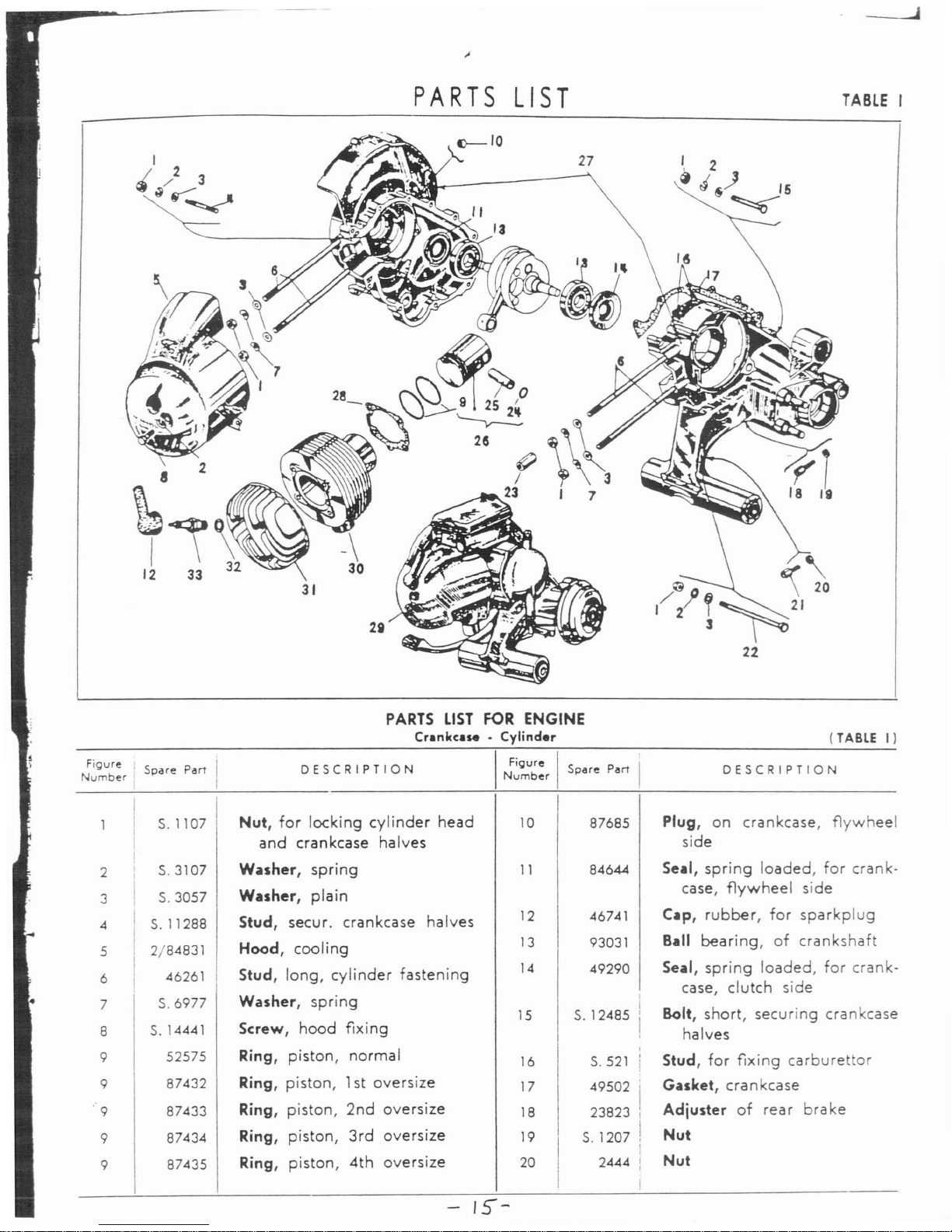
PARTS
LIST
27
a
;\~
12
33 32
31
2a
PARTS
LIST
FOR
ENGINE
Cr.nkc.se
. Cylinder
TABLE
I
(TABLE
I)
.J
Figure I I
N b
. Spare
Part
urn
er
I
DESCRIPTION
I
Fi<;lure
I I
Number
Spare
Pl!IrT
DESCRIPTION
2
3
4
5
6
7
8
9
9
'9
9
9
S.1107
5.3107
5.3057
S.11288
2/84831
46261
5.6977
S.14441
52575
87432
87433
87434
87435
Nut,
for
locking
cylinder
head
and
crankcase
halves
Washer,
spring
Washer,
plain
Stud,
secur.
crankcase
halves
Hood,
cooling
Stud,
long,
cylinder
fastening
Washer,
spring
Screw,
hood
fixing
Ring,
piston,
normal
Ring,
piston,
1st
oversize
Ring,
piston,
2nd
oversize
Ring,
piston,
3rd
oversize
Ring,
piston,
4th
oversize
10
11
12
13
14
15
16
17
18
19
20
87685
84644
46741
93031
49290
5.12485
S.521
49502
I
23823 I
I
S,
1207 ,
I
I
2444 :
I
Plug,
on
crankcase,
flywheel
side
Se.l,
spring
loaded,
for
crank-
case,
flywheel
side
C.p,
rubber,
for
sparkplug
B.II
bearing,
of
crankshaft
Seal,
spring
loaded,
for
crank-
case,
clutch
side
Bolt,
short,
securing
crankcase
halves
Stud,
for
fixing
carburettor
Gasket,
crankcase
Adjuster
of
rear
brake
Nut
Nut
Page 16

P.rt,
II"
for
.nQin.
- Cranke:.t,. -
Cylind.r
-
C~r':
ue<:J
"
89267
4 267
Piston,
4th
oversize
with
Wr
pin
(with
figs.
24-25
- S
Crankcase
assy.
(Figs.
n.
t.
22-17
- 10 - 1 - 3 - 2 - <
15-16T.I;
27-28-3C
9 -
10-31
-
32
-
26
T. I
1 - 4 -
26-24-25
- 3 - :
23-7T.IV;
31-33-3L
41
T.
"I).
Gasket,
cylinder
base
Engine,
g.
a.
Cylinder
Head,
cylinder
Gasket,
copper,
of
sparkplul
Sparkplug,
with
gasket
DESCRIPTION
(TABLE
II
DESCRIPTION
Washer,
shim,
of
clutch
gear
Washer,
plain,
for
securing
clutch
cover
Washer,
spring
Screw,
securing
clutch
cover
Gasket,
between
clutch
cover
and
crankcase
Breather,
with
inserts
Plate,
clutch
centralizing
Spring,
for
fixing
clutch
cen·
tralizing
plate
Thruster,
clutch
lever,
inner,
clutch
Cover,
clutch,
with
inserts
Packing,
between
clutch
cover
and
outer
lever
Spring,
return,
of
outer
clutch
control
lever
87423
97453
89120
99262
93808
92230
318
13903
19301
16821
14457
46740
89858
83806
50100
5.6708
48834
5. 3056
5.3106
5.14413
:7781
26
12
13
27
17
18
19
24
14
15
16
23
28
29
30
31
32
33
20
21
22
I
Figure
NumberISpare
Part
Adjuster
of
clutch
Bolt,
securing
crankcase
halves
Nut,
spacer,
hood
fixing
Circlip,
for
locking
wrist
pin
Wrist
pin
Wrist
pin,1st
oversize
Wrist
pin,
2nd
oversize
Piston,
with
standard
wrist
pin
(with
figs.
24-25-9).
Piston,1st
oversize,
with
wrist
pin
(with
figs.
24-25-9).
Piston,
2nd
oversize
with
wrist
pin
(with
figs.
24-25-9).
Piston,
3rd
oversize
with
wrist
pin
(with
figs.
24-25-9).
DESCRIPTION
DESCRIPTION
I
~~~u~:r
I
Spare
Part I
-
16
-
PARTS
LIST
FOR
ENGINE
Crankshaft.
Clutch
Crankshaft
(with
partn.87442
fig.
5)
Nut,
securing
flywheel
Washer,
shake
proof,
for
nut
securing
flywheel
Key,
woodruff,
for
crankshaft
(flywheel
side)
Bronze
bush
of
con.
rod
small
end
Key,
woodruff,
for
crankshaft
(clutch
side).
Washer
spring,
for
castle
nut
securing
clutch
Nut,
castle,
for
securing
clutch
Spindle,
hollow,
for
hydraulic
shockabsorber
Bush,
bottom,
rubber,ofshock-
absorber
Circlip,
locking
spacer
87421
87422
87
..20 I
2040
46684
5.
1447
5.6615
2/51992
87436
87437
86944
6 97
5
87442
8 20375
9
94727
2
5.12066
I
3 686
7 22313
11
46266 I
21
22
23
24
25
25
25
26
10
40316
26
26
26
Fi"ure
I
.,.
Spare
Parr
Number
I
FiQure I
Spdle
Part
Number
Page 17

_
17_
TABLE
1/
DESCRIPTION
13
\
I~
G I
15
@~
16
2
II
I
Figure
I I
Number
Spllre
Part
DESCRIPTION
25
97984
lever,
outer,
clutch
33
32005
Ring,
elastic,
for
stopping
26
a)
47946
Sp~cer,
clutch
side
clutch
plat~
27
59588
Bush,
rubber,
clutch
side
34
94780
Driving
disc,
external,ofclutch
28
59590
Washer,
plain
35
94425
Plate,
~mooth,
of
clutch
29
98028
Clutch,
g.a.(Figs.
n. 41 -
40
-
36
94743
Plate,
clutch,
with
linings
I
33-42-37-39-38-35
-
37
59109
Washer,
spacer
34-36).
38
94380 Gear,
clutch
30
I
59589
Bush,
rubber,
flywheel
side
39
94379
Plate,
spring,
of
clutch
31
I
47944 Spindle,
hollow,
for
engine
40 22821 Spring,
clutch
I
I
suspension
41
21868
Cup,
clutch
spring
I
32
I
47945 Spacer,
flywheel
side
42
59369
Body,
clutch
I
36
Figure
i I
NumberISpare
Part
Puts
""
of
engine
-
Crankule
• Clutch -
Continued.
.)
Parts
48988or48989
canbeassembled
insteadofspacer
47946,toatlainanaxial
forceinthe
bush
59588togive0-;-
1,5 mm.
(0
-;-
.06")
compression.
Page 18

r
I
TABLE
III
.)
The
total
axial
playofthe
assemblyofthe4gear
pinionsinrespecttotheir
seat
must
be
contained
between
.006"
and
.012".
Should
this
play
exceed
said
tolerances,
the
normal
shoulder
washer
must
be
repla.~ed
by
another
with
proper
oversize.
1
I
S.12131
Nut,
for
securing
wheel
10
46700
Circlip
2 S.3111
Washer,
spring,
for
nut
secu-
11
97181
Axle,
cam,
of
rear
brake
with
ring
wheel
packing
(
fig.
12)
.
3
87714
Washer,
plain,
for
nut
securing
12
S.6714
Packing
wheel
flange
13
78522
Spring,
return,
of
brake
jaws
4 S.12787
Split pin,
for
locking
castle
nut
14
46688
Ring,
locking
ball
bearing
5
S.2314
Nut,
castle,
for
securing
wheel
15
17821
Seledor,
gear
flange
16
7563
Ball
bearing
of
mainshaft
6
2021
Screw,
for
joining
brake
drum
17
7886
Pad
to
flange
18
78170
Jaw,
rear
brake,
with
lining
7
23831
Drum, rear
brake
19
61
Clip,
spring,
for
brake
jaws
8
94535
Flange,
female
spline,
with
20
85673
Bolt,
for
securing cable to
(fig.
1)
brake
links
9
46699
Seal,
spring-loaded
of
main-
21
S.
3204
Split pin, on
pin
for
brake
links
shaft
22
a)
82085
Mainshaft
DESCRIPTION
PARTS
LIST
FOR
ENGINE
Gear
box . R..r
wheel
fl.nge
DESCRIPTION
I
~~~~:r
I
Spare
Part
N
FiQubreISpare
Part
um
er
-
18-
(TABLE
III)
Page 19

Pam
lilt
for
engine.GMr
box
.
Rear
wheel
flange-Ccntlnued.
FigureISpare
Part
umber
23
24
25
26
27
29
30
31
32
33
34
35
36
37
38
42048
94779
42047
S.1426
S.3109
42043
5.
3208
78171
78521
78164
78163
92098
5.13768
47190
a)
18558
DESCRIPTION
Pin,
for
rear
brake
links
link,
brake
link,
brake
Nut,
on
bolt
securing
brake
links
Washer,
spring
Arm,
rear
brake
control
Split
pin,
for
cam
axle
Dust
cover
Packing
washer
Packing
washer
Packing
washer
Stem,
selector
Washer,
tab,
on
selecto(
stem
Bush,
guide,
of
selector
stem
Washer,
shoulder,
normal,
of
gear
pinions
I
FigureISpare
Par
Numoer
38
a)
20321
38
a)
20322
38
a)
20323
38
a)
20324
39
18447
40
a)
51123
41
12869
42 92240
43
a)
59007
44
a)
51124
DESCRIPTION
Washer,
shoulder,
1st
oversize
(thickness:
2,2
mm.
=
0".086)
Washer,
shoulder
2nd
oversize
(thickness:
2,35
mm.
=
0".092)
Washer,
shoulder
3rd
oversize
(thickness:
2,50
mm.
=
0".098)
Washer,
shoulder
4th
oversize
(thickness:
2,65
mm.
=
0".104)
Circlip,
retaining
shoulder
washer
Gear,
3rd
speed
Screw,
for
dust
cover
Gear,
4th
speed
Gear,
2nd
speed
Gear,
low
speed
aj
The
alai
axial
play
of
he
assembly
of
the4gear
pinioninrespect
to
their
seat
must
be
contained
between
.006"
and
.012".
Should
I
IS
play
exceed
saId
tolerances,
the
normal
shoulder
washer
mustbereplaced
by
another
with
proper
oversize.
Figure
I I
Number
Spare
Part
PARTS
LIST
FOR ENGINE
Cush
gear•Kickmrter
DESCRIPTION
I
Figure
I 5
dre
Number
p
(TABLE
IV)
DESCRIPTION
i
1
47160
I
Race,
roller
bearing
of
main-
18
89913
Washer,
plate,
of
cush
drive
shaft
springs
2
82086
Cage,
roller
bearing
19
17887
Spring,ofcush
drive
3
81842
Roller
20
92074
Drive,
cushion,
g.
a.
(Figs.
n.
4
47161
Washer,
shoulder,
roller
bea-
19-21-22
- 18 -
17)
ring
21
58677
Gear,
multiple
5
I
47218
Spring,
return,
of
kickstarter
22
89911
Gear,
outer,
of
cush
drive
6
I
77413
Sedor,
starting
23
S.10790
Rivet,
for
securing
blades
7
I
46631
Plug
24
48002
Pad,
blades
I
8
I
97338
Kickstarter
g.
a.
(Figs.
n. 9 -
25
54071
Blade,
long,
for
sta
rtingsector
I
10-11
-12-13)
26
48000
Blade,
short,
for
starting
sector
9 49642
Rubber
sleeve
27
5.6637
Circlip,
for
locking
multiple
10
I
5.8507
Bolt,
securing
kickstarter
gear
ball
bearing
11
I
S.3109
Washer,
spring
28
2457
Roller,
for
multiple
gear
12
I
5.3060
Washer,
plain,
of
kickstarter
29
94417
Layshaft
13
S.1109
Nut
30 32494
Ball
bearing,
of
multiple
gear
14
S.6721
Packing
31
S.13940
Wuher,
plain,
for
nut
securing
15
46742
Buffer,
for
starting
sector
layshaft
16
58680
Geary
starting
32
58560
Washer,
spring,
for
nut
secu-
17
5.
10776
Rivet,
for
sec.
plate
washer
ring
layshaft
I
I
I
Page 20

TABLE
IV
5--
-
31
'---------
~-----~/
20
PARTS
LIST
FOR
ENGINE
Flywheel
M.gneto•Fin
(TABLE
V)
Figure
IS P rt
Number
pare
a
DESCRIPTION
I
Figure
I I
Number
Spare
Part
DESCRIPTION
6
S.
3055
7 S.3105
8
S.
10047
. 9
46675
10
97191
1
2
3
4
5
46764
14501
662
674
87594
Cable,
earth,
with
terminal
Terminal
Terminal
Circlip,
for
flywheel
extraction
Stator,g.a.
(Figs.n.42-23
-
33-22-34-36-24-30
-
32-37-46
- 1 -
38-39
-
45-21-44-47
- 6 -
35
-
7 -
27-31-28-29).
Washer,
plain,
for
screws
se-
curing
stator
and
coils
Washer,
spring,
for
screw
se-
curing
stator
Screw,
for
securing
stator
Cam
Flywheel
fan
(Figs.n.16
- 12 -
9-14-13-15)
11
12
13
14
15
16
17
18
19
20
21
22
23
97189
6562
S.10775
78070
S.
12533
2946
S.
3056
2856
47577
S.3106
83408
625
622
Flywheel,
magneto
g. a.
(Figs.
n.5-10)
Washer,
plain,
of
cam
Rivet,
for
securing
cam
Dust
cover
Washer,
spring
Screw,
short,
for
securing
fan
casing
cover
and
dust
cover
Washer,
spring
Screw,
long,
for
securing
fan
casing
cover
Cover,
fan
casing
Washer,
spring
Pad,
securing
low
tension
coil
No.3
Fork
spring
Washer,
shim,
of
breaker
_
?n
_
Page 21

TABLE
V
22
r
'Wi
07
~ir
'/1
):I}I5
I.
12
13
l~
6
l
9
/
40
Puts
list
for
engine
-
Flywheel
Magneto•Fan-Continued.
Figure
I I
Number
Spare
Part
DESCRIPTION
I
Figure
II
I
Number
Spare
Part
DESCRIPTION
-21
24
25
26
27
28
29
30
31
32
33
34
35
36
97478
94357
16418
5.12331
S.
13800
5.13801
16419
S.
12332
16420
624
3213
S.3103
16417
i
Gusset-breaker
assy
(Figs.
n.
25 -
26)
Breaker
with
platinum
point
Gusset,
contact
Bolt,
retaining
coil
terminals,
condenser
and
breaker
blade
Washer,
plain
Washer,
insulating
Ring,
insulating
Screw,
securing
blade
with
cam
greasing
felt
Cam
Nut
Screw,
securing
condenser
and
felt
blad~
Washer,
spring
for
felt
blade
Axle,
breaker
37
16421
38
83386
39
83125
40
84737
41
86475
42
603
43
46766
44
83545
45
83387
46
46750
47
86482
48
86483
Blade
felt,
with
inserts
Coil,
low
tension,
No.
Stator
Tube,
for
part
86475
(Fig.41)
lead,
plug,
with
inserts
Screw,
for
securing
coils
Grommet
Coil,
low
tension,
NO.3
Coil,
low
tension,
No. 2
Condenser
Coil,
H.
T.
Coil,
ignition,g.a.
(Figs.n.41
43-47).
Page 22

·1
I
TABLE
VI
9
19
~
PARTS
LIST
FOR
ENGINE
(TABLE
VI)
Cuburettor
. Air
Cleaner
Figure
I
Spare
Part
I
DESCRIPTION
I
Figure
I
Spare
Part
DESCRIPTION
Number
Number
I
87856
I
Cover,
air
cleaner,
with
plug
15
50274
Plug
(
fig.
2)
16
59708
Air
cleaner,
body
2
87975
Plug,
on
air
cleaner
17
94245
Joint
3
58364
Packing
18
92181
Carburettor,
Dell
'Orto
SI
20/15
4
84797
Puking,
air
cleaner
C -
Typeg.a.
(Figs.
n.
41
-
5
S.
14436
Screw,
for
air
cleaner
body
56-27-58-55-60-57
-
6
S.3105
Washer,
spring
59-33-37-50-46-48
-
7
S.
10074
Screw,
for
air
cleaner
body
40-45-51-49-53
- 32 -
8
59710
I
Air
filter
26-35-36
- 20 -38-39-
9
92263
I
Air
cleaner,
g.a.(Figs. n. 15 -
43
- 22 - 25 -23- 24 -
44
-
3 - 16 - 8
- 4 - 1 -
6·7-
52-47-54
- 34 -
42-21
5 -
19)
I
61
)
10
49542
Screw,
for
securing
carburettor
19
S.
14583 I
Screw,
for
air
cleaner
Washer,
spring
I
Screw,
fo
r cover
of
iets
11
S.3109
20
85306 ;
12
S.13762
Washer,
plain
21
92772
Cover,
for
jets
13
94244
Gasket,
forcarbu
rettor
22
85795
Jet,
idling
14
S.14540
Screw,
for
air
cleaner
body
23
89188
Air
hole
on
mixer
top
-22-
Page 23
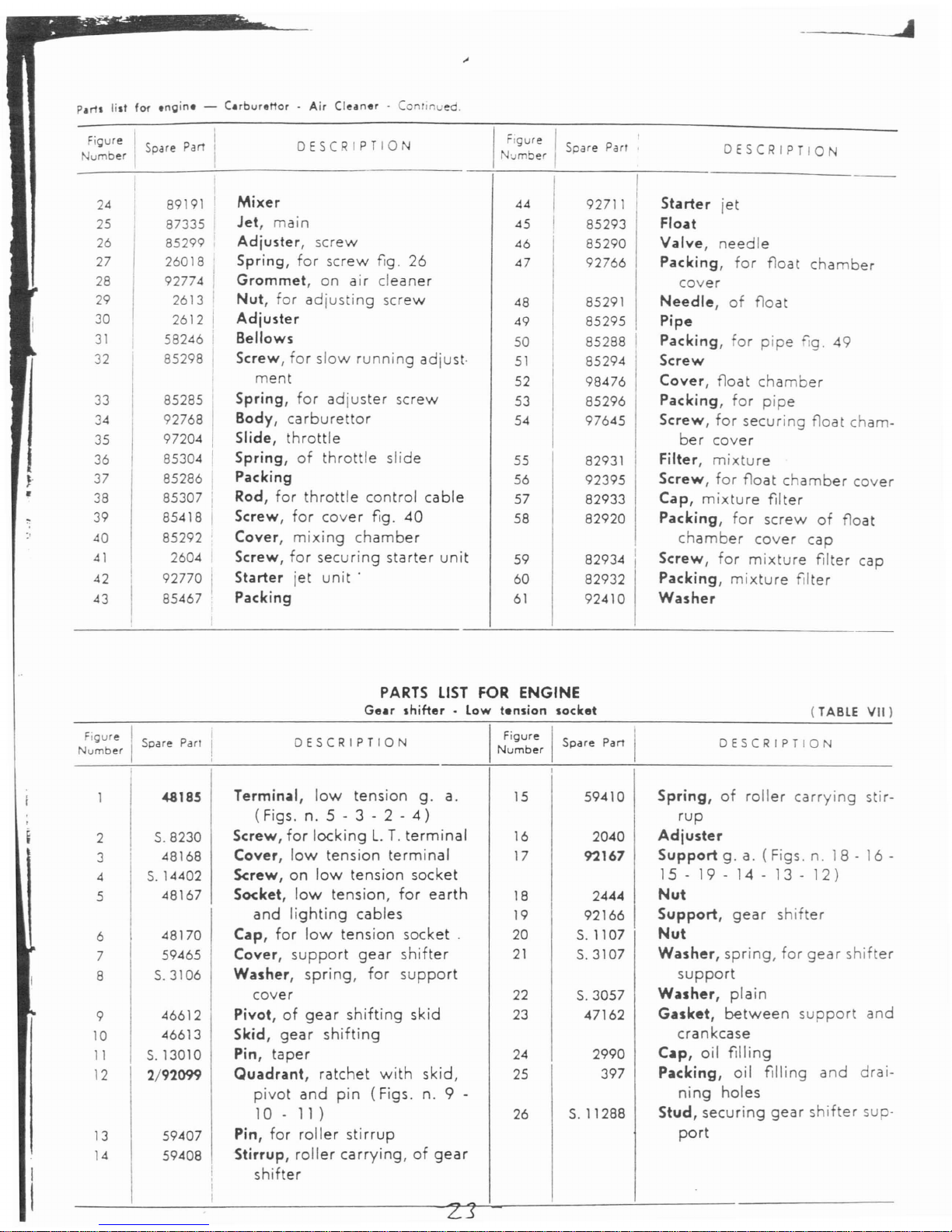
--~
....
Parts
list
for
engine
-
Carburettor.Air
Cleaner·
Conrlnued.
cap
cover
oat
ber
cham-
DESCRIPTION
I
Figure I '
b
Spare
Parr
\.1m
er
44
I
92711
Starter
jet
45
I 85293
Float
46
I
85290
Valve,
needle
47
92766
Packing,
for
float
cham
cover
48
85291
Needle,
of
float
49 85295
Pipe
50
85288
Packing,
for
pipe
fig.
49
t·
51
85294
Screw
52
98476
Cover,
float
chamber
53 85296
Packing,
for
pipe
54
97645
Screw,
for
securing
float
ber
cover
55
82931
Filter,
mixture
56
92395
Screw,
for
float
chamber
57 82933
Cap,
mixture
filter
58 82920
Packing,
for
screw
of
fl
chamber
cover
cap
it
59
82934
I
Screw,
for
mixture
filter
60 82932
Packing,
mixture
filter
61
92410
Washer
DESCRIPTION
Mixer
Jet,
main
Adjuster,
screw
Spring,
for
screw
fig.
26
Grommet,
on
air
cleaner
Nut,
for
adjusting
screw
Adjuster
Bellows
Screw,
for
slow
running
adjus
ment
Spring,
for
adjuster
screw
Body,
carburettor
Slide,
throttle
Spring,
of
throttle
slide
Packing
Rod,
for
throttle
control
cable
Screw,
for
cover
fig.
40
Cover,
mixing
chamber
Screw,
for
securing
starter
un
Starter
jet
unit'
Packing
Figure I
Spare Part
umber
24
89191
25
87335
26
85299
27
26018
28
92774
29
2613
30
2612
31
58246
32
85298
33
85285
34
92768
35
97204
36
85304
,.
37 85286
•
38
85307
39
85418
40
85292
41
2604
42
92770
43
85467
PARTS
LIST
FOR ENGINE
Gear
shifter
• Low
tension
socket
Figure I Spare Parl
Number
DESCRIPTION
I
~~~u~:r
I
Spare
Part
(TABLE
VII)
DESCRIPTION
2
3
4
5
6
7
8
9
10
11
12
13
14
<48185
5.8230
48168
S.14402
48167
48170
59465
5.3106
46612
46613
S.13010
2/9'2099
59407
59408
Termin~l,
low
tension
g.
a.
(Figs.n.5 - 3 - 2 -
4)
Screw,
for
lockingL.T.
terminal
Cover,
low
tension
terminal
Screw,
on
low
tension
socket
Socket,
low
tension,
for
earth
and
lighting
cables
Cap,
for
low
tension
socket
Cover,
support
gear
shifter
Washer,
spring,
for
support
cover
Pivot,ofgear
shifting
skid
Skid,
gear
shifting
Pin,
taper
Quadrant,
ratchet
with
skid,
pivot
and
pin
(Figs.
n. 9 -
10-11)
Pin,
for
roller
stirrup
Stirrup,
roller
carrying,
of
gear
shifter
15
16
17
18
19
20
21
22
23
24
25
26
59410
2040
92167
2444
92166
5.1107
5.3107
5.3057
47162
2990
397
5.11288
Spring,
of
roller
carrying
stir-
rup
Adjuster
Support
g.a.(Figs.n.18-16
-
15
- 19 -
14-13-12)
Nut
Support,
gear
shifter
Nut
Washer,
spring,
for
gear
shifter
support
W~sher,
plain
Gasket,
between
support
and
crankcase
C~p,
oil filling
Packing,
oil filling
and
drai-
ning
holes
Stud,
securing
gear
shifter
sup·
port
Z3
Page 24

TABLE
VII
17
8
/
~'~
7
I
~
~
............-9
}
~_IO
12
~~
~My'~
~~jh~6
~-18
~_19
~'()
0
~
/ I \
22
21
20
-=->
,I
26
25
I
2~\~
~
i
I,
: I
'"
~
I
!
:i
PARTS
LIST
FOR
CHASSIS
Saddle
• Fuel
tank•luggage
carrier
, I
I
(TABLE
VIII)
~~~~:r
I
Spare
Part I .
DESCRIPTION
I
Figure
I
Number
Spare
Part
DESCRIPTION
5 85247
I
167246
7
44:5
8 84222
9
I
2319
10
4433
11
S.3212
2
3
4
87802
97341
84424
97232
I
Saddle,g.a.
(Figs.n.49
·41
-
39-46-45-42
- 3 -
47
-
31-50-51-2-48-40)
Cover,
saddle
Grip,
on
saddle
Tank,
fuel,
with
filling
cap
(Figs.
n. 9 -10- 7 - 6 -
8-
5 -
11)
Transfer,
indicating
gas
- oil
ratio
of
fuel
Cap,
filler,
of
fuel
tank,
with
inserts
Screw,
tie,offiller
cap
Nut,
wing,
for
filler
cap
Packing,
of
filler
cap
Pivot
Split
pin
for
supporting
tie
screw
12
13
14
15
16
17
18
19
20
21
22
23
24
82994
94147
2398
S.3107
S.14441
83995
3221
87467
84262
9641
9640
26042
26041
Filter,
mixture
Packing,
between
chassis
and
fuel
tank
Screw,
securing
saddle
Washer,
spring,
for
securing
carrier
and
fuel
tank
Screw,
securing
carrier
and
fuel
tank
Carrier,
package
Strap,
pipe
fastening
Pipe,
plastic,
from
fuel
tap
to
ca
rbu
rettor
Grommet
Sediment
bowl
tie -
rod
Sediment
bowl
Packing
Filter
- 24 -
Page 25
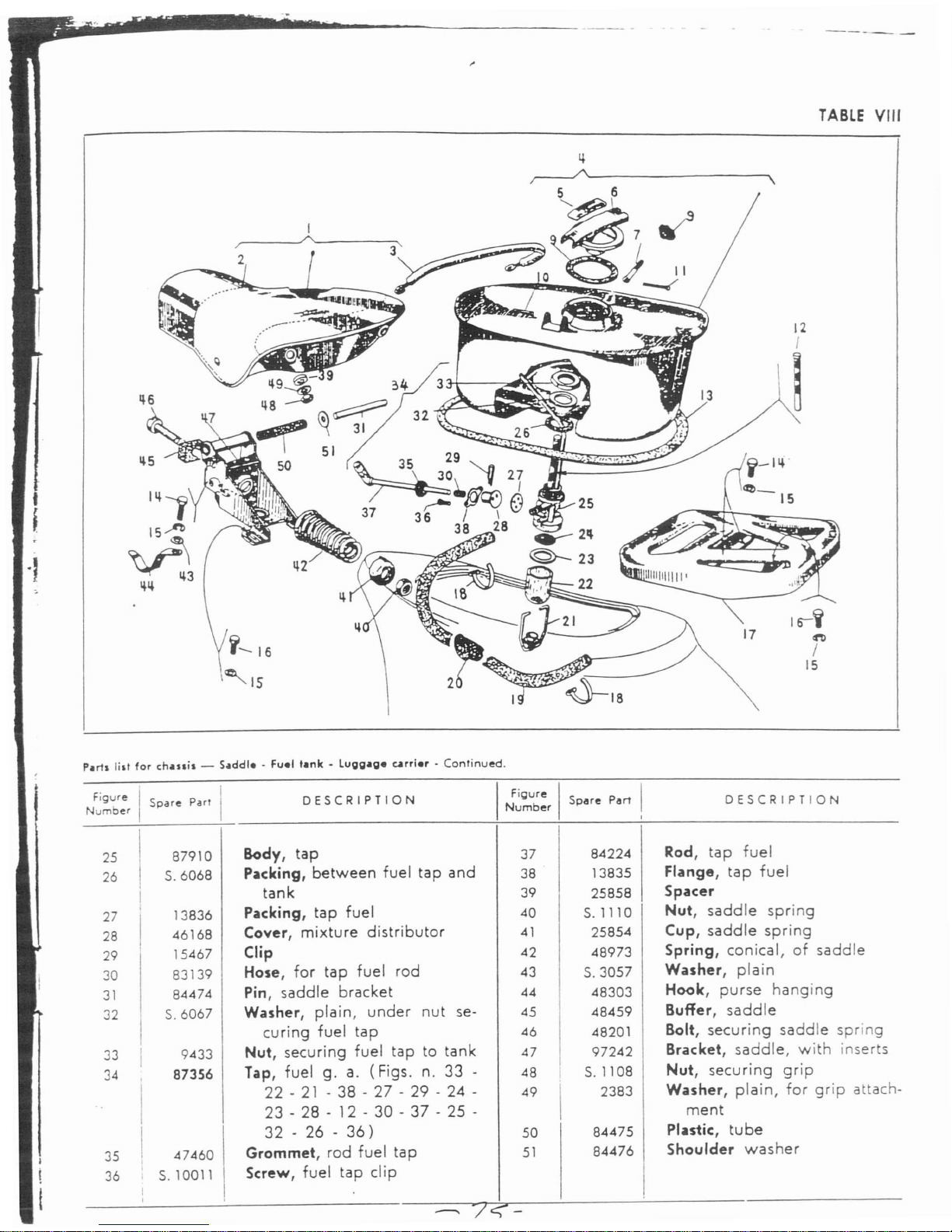
i..-
....
--.
......
----------
----
TABLE
VIII
t
;
oJ
Puts
lill
for
ch.u,i,
-
S.ddle-Fuel
t.nk
•
Lugg.ge
arrier
.
Continued.
DESCRIPTION
I
~~~~:r
I
Spare
Part
I
----
7
c;-
DESCRIPTION
I
25
87910
Body,
tap
37
84224
Rod,
tap
fuel
26
5.6068
Packing,
between
fuel
tap
and
38
13835
Flange,
tap
fuel
I
tank
39
25858
Spacer
27
I
13836
Packing,
tap
fuel
40
5.1110
Nut,
saddle
spring
28
I
46168
Cover,
mixture distributor
41
25854
Cup,
saddle
spring
29
15467
Clip
42 48973
Spring,
conical,
of
saddle
30
83139
Hose, for tap fuel rod
43
5.3057
Washer,
plain
31
84474
Pin,
saddle
bracket
44 48303
Hook,
purse
hanging
32
5.6067
Washer,
plain,
under
nut
se-
45 48459
Buffer,
saddle
I
curing fuel
tap
46
48201
Bolt,
securing
saddle
spring
33
I
9433
Nut, securing fuel tap to tank 47
97242
Bracket,
saddle,
with
inserts
I
34
87356
Tap, fuel g.
a.
(Figs. n.
33
- 48
i
5.1108
Nut,
securing
grip
I
22 -21- 38 - 27 - 29 - 24 -
49
2383
Washer,
plain,
for
grip
attach-
'.
23 - 28 - 12 - 30 - 37 - 25 -
ment
I
32 - 26 -
36)
50
84475
Plastic,
tube
35
47460
Grommet,
rod fuel
tap
51
84476
Shoulder
washer
I
36
5.10011
Screw,
fuel
tap
clip
I
I
Figubre I
Spare
Part
I
Num
er
Page 26
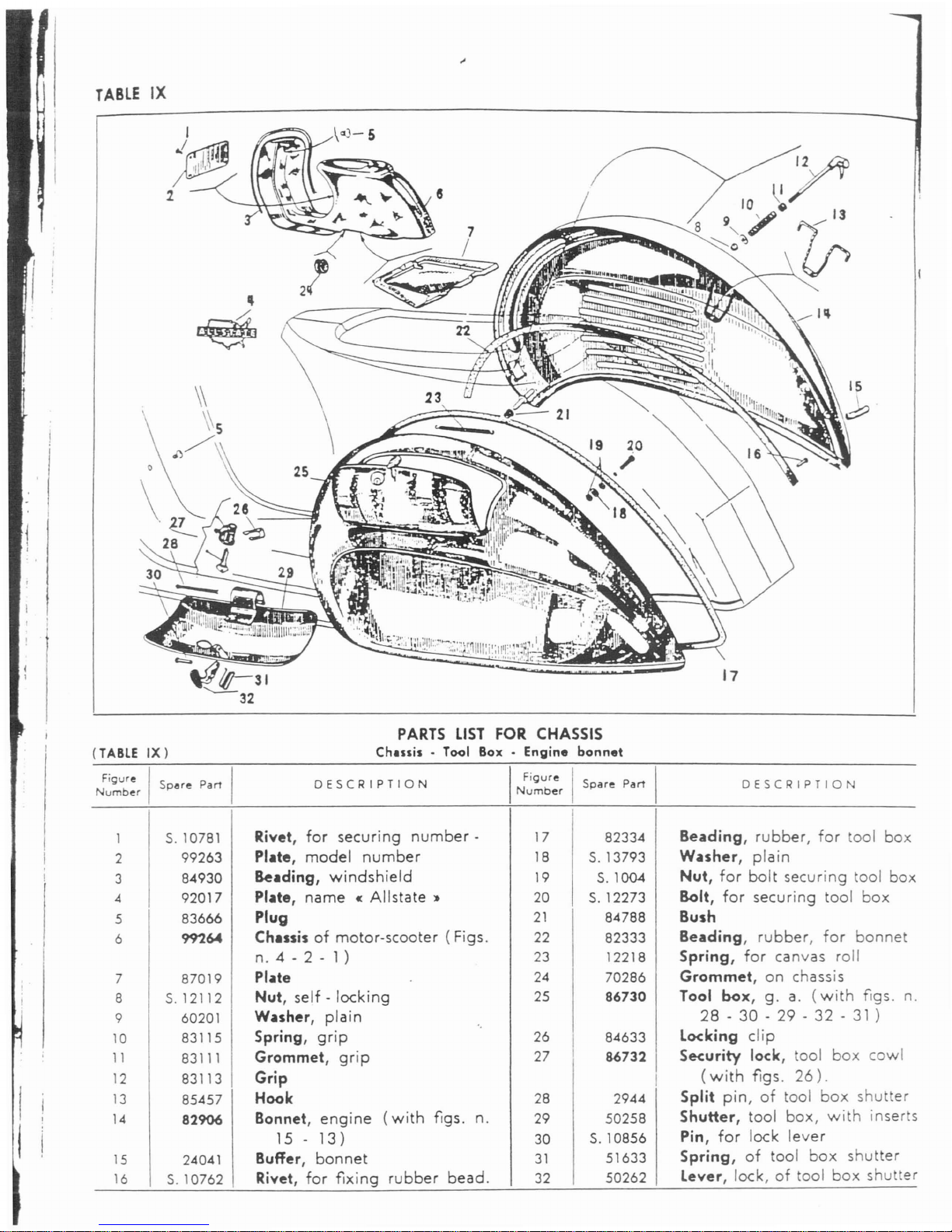
1
S.10781
Rivet,
for
securing
number-
17
82334
Beading,
rubber,
for
tool
box
2
99263
Plate,
model
number
18
S.13793
Wuher,
plain
3
84930
Beading,
windshield
19
S.l004
Nut,
for
bolt
securing tool
box
4 92017
Plate, name «
Allstate
:t
20
S.12273
Bolt,
for
securing
tool
box
5
83666
Plug
21
84788
Bush
6
99264
Chusis
of
motor-scooter
(Figs.
22
82333
Beading,
rubber,
for
bonnet
n. 4 - 2 - 1)
23
12218
Spring,
for
canvas
roll
7 87019
PI.lte
24
70286
Grommet, on chassis
8 S.12112
Nut,
self·
locking
25
86730
Tool box,
g.
a.
(with
figs.
n.
9 60201
Wuher,
plain
28-30
- 29 - 32 -31)
10
83115
Spring,
grip
26
I
84633
locking
clip
11
83111
Grommet,
grip
27
86732
Security lock, tool
box
cowl
12
83113 Grip
I
(with
figs.
26).
13
85457
Hook
28
2944
Split
pin,
of
tool
box
shutter
14
82906
Bonnet,
engine
(with
figs. n.
29 50258
Shutter,
tool
box,
with
inserts
15
-
13 )
30
S.10856
Pin,
for
lock
lever
15
24041
Buffer,
bonnet
31
51633
Spring,
of
tool
box
shutter
16
S.10762
Rivet,
for
fixing
rubber
bead.
32
50262
lever,
lock,oftool
box
shutter
PARTS
LIST
FOR
CHASSIS
Chusis
• Tool Box . Engine bonnet
DESCRIPTION
I
Figure
I
Number
Spare
Part
DESCRIPTION
N
FigubreISpllre
Part
um
er
TABLE
IX
(TABLE
IX)
Page 27

TABLE
X
I~
18~
17-e
~-
6
(1
__
5
N
FigUbreISpare
Part I
um
er
PARTS
LIST
FOR CHASSIS
Reu
suspension spring . Reer
damper
DESCRIPTION
I
~~~~:r
,
Spare
ParI
(TABLE
X)
DESCRIPTION
1
S.3109
Washer,
spring,
for
shock
8 70635
Tube,
protection,
of
shock-ab-
absorber
anchoring
pin
sorber
2
70646
Spring,
rear
suspension
9 70641
Stem
of
shock-absorber
3
70658
Shock - absorber,
hydraulic,
10
S.6018
Washer,
support,
spring
rear,g.a.
(Figs.n.28-29
-
11
22827 Spring,
for
valve
pin
24
- 8 -
25-26-20-22
-
23.27
- 7 -
21
-
35)
12
17285
Pin,
valve
4
60536
Bracket,
elastic
13
93468 Piston,
of
shock-absorber
5
S.3108
Washer,
spring
14
32812
Spring,
for
valve
pin
6
S.12109
Nut,
securing
brackettoframe
15
S.
13768
Washer,
support,
spring
7
70634
Nut,
spacer,
of
shock-absorber
16
17122
Ring, lock,
of
piston
I
I
Page 28

Parts list for
chanis
-
Rur
ouopenoion
opring
-
Rear
dafuper
Con
JESC:(I?
ION
Spar'!
Parr
Figure
Spare
ParI
0
ESC
RIPTION
I
Numoer
I
---~----------
----------------
-
--_.-
----------
I
i '
I
I
17
18
19
20
21
22
23
24
22828'
Valve
discharging, with inserts
17385 Washer, seal
84603 Spring,
of
seal
washer
70640 Tube,
inner,ofhydraulic
shock-
absorber
5.6721'
Packing
83819
Bush,
guide,
of
shock - absor-
ber
stem
84608 Seal,
of
shock -
absorber
48591 Cap,
threaded,
of
shock - ab-
sorber
27
28
29
30
31
32
33
70647
2/22832
70638
S.
1214
S.3114
S.
14689
81803
Stem,
g.a.(Figs.
n.
16
- 2
11
-14-9-13-10-15:
Valve,
discharge
g.a.(Figs.
n
18-17-19)
Body,
shock-absorber
Nut,
for
securing
engine
to
chassis
Washer,
spring
Bolt,
securing
shock -
absorber
bottom
Bolt,
securing
engine
to chassis
S.
13940,
Washer,
spacer
,
~.,
~,
'lo
"
25
26
57104
48596
Buffer
Buffer
34
35
S.
13957
Washer,
suppor
. '
.J
PARTS
LIST
FOR
CHASSIS
Ch.nnels
. Center
sund
. Silencer
(TABLE
XI)
N
FiQubreISpare
Pan
um
er
DESCRIPTION
I
~~~u~:r
I
Spare
Pan
DESCRIPTION
81098
Cap,
strip
9
81925
2
S.10869
Rivet,
securing
outer
strips
cap
of
floorboard
10
a)
47243
3
S.10868
Rivet,
securing
inner
strips
cap
11
S.10805
of
floorboard
4
89156
Cap,
strip
12
93207
5
93209
Strip,
short,offloorboard,R.H.
13
93211
6
93210
Strip,
short,offloorboard,L.H.
14
S.3107
7
93212
Channel,L.H.
(outer)
8
3907
Rivet, secu ri
ng
outer
strips
of
15
S.1107
I
floorboard
I
I
a)
Order
by
meler~
Dr
feel.
Ii
- 28 -
Muffler,
with
figs.
n.
15-16
-
14 )
Strip,
rubber,
of
floorboard
Rivet,
securing
inner
strip
of
floorboard
Channel,
R.
H.
(inner)
Channel,
R.
H.
(outer)
Washer,
spring,
for
securing
muffler
to
cylinder
Nut,
for
securing
muffler
to
cylinder
Page 29

at
d
II
\
..
~I
\;Y
~
.
----
,~,
J
TABLE
XI
-4
Puts
lid
for
eNub
-
Ch.nnels-Center
&tand -
Silencer
-
Continued.
Figure I I
Number
Spare
Part
DESCRIPTION
I
:~~u~:r
I
Spare
Part
I
DESCRIPTION
16
5.3057
Wuher,
plain
25
S.3106
Wuher,
spring,
for
center
Ch.annel,
L.
H.
(inner)
stand
attachment
17
93208
Screw,
self-locking
26
S.1106
Nut,
for
securing
stand
18
S.
897
27
54146
Shoe,
R.
H.
19
85073
R.H.mat
retainer
strip
54147
Shoe,
L.
H.
27
19
85074
l.
H.
mat
retainer
strip
28
54140
Stand,
with
rubber
shoes
( Fig.
20
85072
Rubber
mat
n.
27)
21
47872
Spring,
return,
of
stand
legs
29
S.12306
Bolt, secur.
muffler
to
engine
Spring
retainer
clip
30
5.3060
Washer,
plain,
for
screw
se-
22
77252
curing
muffler
to
engine
23
S.12281
Bolt, securi
ng
stand
Washer,
spring,
for
securing
31
S.3110
24
59188
R.
H.
clip,
of
centre
stand
muffler
to
engine
24
59189
l.
H.
-clip,
of
centre
stand
I
/'1
-
Page 30

.'
I
,j
,
i
I
I
i
TABL£
XII
17
23
I
.-
($)
. -
#8
28
~l
PARTS
LIST
FOR
STEERING
COLUMN
Steering column •
Mudguard
. Front Wh..1 hub
(TABLE
XII)
FigureISpare
Part
Number
DESCRIPTION
I
FiQure
I I
Number
Spare
Part
DESCRIPTION
2
3
4
5
6
7
8
9
S.12131
S.3111
2002
2021
S.1105
S.3105
60201
S.14467
2957
Nut, securing
wheel
Washer,
spring,
for
nut
secu-
ring
wheel
Drum,
front
brake
Screw,
clamping
brake
drum
Nut,
for
bolt
securing
mud-
guard
Washer,
spring,
under
nut
se-
curing
mudguard
Washer,
plain,
for
bolt
securing
mudguard
Bolt, securing
mudguard
Bolt,
for
securing
mudguard
to
steering
column
10
11
12
13
14
15
16
17
18
19
S.
3055
86895
85508
89301
8440
97196
25641
22001
61
94534
Washer,
plain,
for
securing
mudguard
Crest,
with
fig.
12
Ring,
clamp
Mudguard,
with
crest
fig.
11
Shoulder,
rod
Steering
column,
with
inserts
Hub,
front
wheel,
with
plug
and
shoulder
rod
(Fig.
n.
14
)
Jaw,
brake,
with
lining
Clip,
spring,
for
brake
jaws
Axle,
front
wheel
with
fig.
1
Page 31

St••ring
column.Mudgu.rd
FrontWh••1hub
. Conti
ued.
P.rt1
lilt
tor"••
ring
Column
FiQure I
Spare
ParI
Number
DESCRIPTION
Ball
bearing,
for
front
wheel
axle-R.
H.
side
Washer,
lock,
for
ball
bearing
Nut,
securing
front
wheel
axle
Nut,
locking
ball
bearing
Bush,
for
front
wheel
bearing
rollers
Washer
shoulder
Cover,
dust,
spindle
front
wheel
Washer,
shoulder
Nut,
securing
front
wheel
spindle
Washer,
spring,
under
nut
se-
curing
front
wheel
spindle
Washer,
plain,
for
nut
securing
front
wheel
spindle
Washer,
spring
2800
2007
2443
2019
18247
5.3060
32386
5.1210
5.3110
S.
13810
32381
5. 12528
34
35
36
37
38
39
40
41
42
43
44
45
I
Figure
!
I'
Number!Spare
ParI
DESCRIPTION
Axle,
anchoring
trunnion
and
brake
jaws
Spring,
return,
of
brake
jaws
Seal,
front
wheel
axle
Spindle,
front
wheel
Ball
bearing,
for
front
wheel
axle-L.
H.
side
Washer,
shoulder
Ring,
shoulder,
for
rollers
Washer,
plain,
for
nut
securing
trunnion
axle
Roller,
bearing,
of
front
wheel
Washer,
spring,
under
nut
se-
curing
trunnion
axle
Washer,
spacer
Nut,
securing
trunnion
axle
lubricator,
stauffer
Washer,
plain,
for
stauffer
lu-
bricator
5598
25990
2018
16781
2802
32389
32385
I
5.3058
I
5021
5.3108
15982
5.1108
19556
S.
13840
20
21
22
23
24
25
26
27
28
29
30
31
32
33
PARTS
LIST
FOR
STEERING
COLUMN
Front
suspension
. Security lock
(
TABLE
XIII)
Figure I
Spare
ParI
DESCRIPTION
I
Figure
I
Spare
Part
DESCRIPTION
Number
Number
I
11109
Ring,
threaded,
for
locking
7
I
19264
Washer,
protection,
of
steering
steer.
colum
top
ball
bearing
column
bottom
ball
bearing
2
3751
Washer,
lock,
of
steering
co-
8
I
55986
Seat,
upper,ofsteering
column
lumn
to
ball
bearing
I
top
ball
bearing
3
26383
Cover,
dust
9
I
77024 Ball
cage,
for
steering
column
4 56642
Seat,
upper,ofsteering
cotumn
I
top
bearing
bottom
baIIbeari
ng
10
93041
Seat,
lower,
of
steering
column
5
77023
Ball
cage,
for
steering
column
i
top
ball
bearing
bottom
bearing
11
82416
lock,
security
I
6
55989
Seat,
lower,ofsteering
column
12
12643
Washer,
for
threaded
ring
of
bottom
ball
bearing
security
lock
~
(3~'
Page 32

DESCRIPTION
12
III
'b
~
~
25
26 33
2i
,27
I q
~~
__
------"
~~30
II
\
2.8
~32
I
Figure
I
Number
Spare
Par'
-
32
-
DESCRIPTION
Front
IUlp.nlion-S.curity
lock-Continued.
13
S.1108
Nut,
securing
front
suspension
24
19556
I
Lubricator,
stauffer
spring
25
2040
i
Adjuster
of
front
brake
14
S.3108
Washer,
spring,
under
nut
se-
I
curing
spring
top
26
2444
I
Nut,
jam,
for
front
brake
adju-
ster
15
35623
Plate,
top
16
35585
Spring,
front
suspension
27 2036
I
Bolt,
securing
cable
to
brake
i
links
17
S.1109
Nut,
securing
spring
bottom
i
18
S.3109
Washer,
spring,
under
nut
28
2083
I
Pin,
for
brake
links
se-
!
curing
spring
bottom
29
97590
Lever,
front
brake
19
35582
Plate,
bottom
30
5.1207
Nut,
on
bolt
securing
brake
20
11623
Packing,
for
trunnion
links
21
S.13770
Washer,
plain,
for
trunnion
31
97108
Link,
front
bra
ke,L.H.
22
S.
13771
Washer,
plain,
for
trunnion
32
S.
3204
Split
pin,
on
pin
for
brake
links
23
35581
Trunnion
for
front
suspension
33
83608
Link,
front
brake,
R.
H.
I
spring
FiQure I I
Number
Sp<lre Part
TABLE
XIII
".m
Iht
for
It_ring
c.olumn
Page 33

(TABLE
XIV)
TABLE
XIV
II
~
/10
~
........
9
@
/)-19
--
.......
0-
7
~'6
/7
13~@
I
II;
PART
LIST
FOR
HANDLEBARS
Handlebars.Controls
2\
DESCRIPTION
I
Figure
I
N
b
I
Spare
Part
umer,
I
DESCRIPTION
I
I
1
70578
Lever,
clutch
and
front
brake
16
29928
Tube,
with
inserts,
for
gear
I
control
change
control
I
Wuher,
spring,
for
securing
17
S.1105
Nut
2
I
17492
Washer,
spring
control
levers
18
S.12528
19
84240 Lever
throttle
control
3
I
97734
Washer
20
S.12329
Screw
4
I
97733
Washer
21
99268
Handlebars,
g.a.(Figs.
n. 2 -
5
S.14629
Screw,
securing
control
levers
1 - 4 -
23
- 12 - 3 - 7 - 8 -
6
I
60566
Wuher,
plain
6 - 15 -
19
- 16 -
26-22
7
60565
Washer,
spring
17
- 18 - 10 -
27-28-11
I
8
I
60557
Geu
change
crank
24
- 13 -
20
- 5 - 9 -
14)
I
9
I
S.
13880
Washer,
plain
Tube,
for
throttle
control
I
22
94370
10
S.3106
Washer,
spring
23
60304
Rubber,
twistgrip
11
I
S.12281
Bolt
24
S.12136
Nut,
for
screw
securing
control
12
I
60312
Washer,
spacerongear
change
levers
sleeve
25
51220
Switch,
housing
13
S.
12355
Bolt,
securing
handlebars
to
26 98481
Handlebar
casting
(with
fig.
steering
column
25)
14
S.13792
Washer,
plain
27
S.12030
Nut
15
84239 Plate,
anchor
28
S.
3110;
Washer,
spring
FigureISpare
Part
Number
- 33
--
Page 34

1 93282
Wire,
gear
change
control,g.a.
13
S.3109 Washer,
spring
(Figs.n.6-5-4)
14
S.
3204 Split
pin
2 14657 Nipple
15
92796
Pin,
for
brake
links
3
a)
2174
Ferrule
16
S.1426
Nut,
for
bolt
securing
cable
to
4
26247
C.ble,
gear
change
control,
I
brake
links
with
nipple
fig. 2
17
i
15350 Tube,
protection
I
5
26249
Terminal
18
I
82385
Clip,
gear
change
control
I
6
93280
Sheath,
for
clutch
and
gear
19
I
57321
Protective,
bellows
change
control
cables,
with
20
I
15395
I
Nipple,
threaded
ferrule
fig. 3
21
I
S.10016
I
Screw,
clamp,
for
gear
change
7
S.11510
Pin,
locking,
for
rear
brake
I
control
cable
pedal
22
83333
Clip,
rear
brake
8
I
94451
Rear
brake
pedal
g.
a.
(with
23
I
9393<' Sheath,
gear
change
control
I
fig.
9)
cable,
with
ferrule
fig.
24
9
93100
Rubber
sleeve,
brake
pedal
24
a)
23825
Ferrule
10
85673
Bolt,
securing
cables
to
brake
25
85547
Cable,
rear
brake
control
links
26
93953
Wire,
rear
brake,
g.
a.
(Figs.
11
I
92795
link,
rear
brake,L.H.
n.
25-23)
12
I
92794 Link,
rear
brake,
R.
H.
27 97326
Clip,
for
gear
change
sheats
PARTS
LIST
FOR
CONTROLS
Gear
change
and
rear
brake
control
cables•Pedal
DESCRIPTIO
I
Figure
,
N
b
Spare
ParT
'
um
er
.
DESCRIPTION
N
FigubreISpare
ParT
um
er
TABU
XV
(TABLE
XV)
i.
a)
Ferrules
No.
2174
and
23825
must
be
lightly
squashed
on
the
cable
sheath
on
assembly.
-34-
Page 35

TABLE
XVI
(TABLE
XVI)
DESCRIPTION
PARTS
LIST
FOR
CONTROLS
Front br.lce, throttle, clutch control
ubles
. Choice
DESCRIPTION
I
~~~~:r
I
Spare
Part I
Spare
Parr I
I
I
!
i
Grommet
I
I
Nipple,
carburettor
side
1
I
77055
13
24929
I
2
I
50188
Sheath,
starter
with
ferrule
14
19093
I
Sheath,
for
front
brake
control,
fig.
4
cable,
with
ferrule
fig.
4
3
I
92371
Cable,
starter
15
81345
I
Cable,
front
brake
control,
with
4
a)
2174
Ferrule
,
I
nipple
fig.
9
5
50207
Spring,
starter
control rod
16
I
84810
Wire,
throttle
control,
g.
a.
6
2/49625
Starter
control
rod I
I
(Figs.
n. 7 - 13 -
21-12)
7
19079
Sheath,
throttle
control,
with
17
I
85051
Wire,
front
brake
control,g.a.
ferrule
fig.
4
I
I
(Figs.
n. 14 -
15)
Cable,
clutch
control,
with
nip-
I
Wire
clutch
control,g.a.
(Figs.
8
84783
18
I
98411
I
pies
fig.
9
I
n.9-7-8)
I
9
I
2777
Nipple
19
I
48171 Grommet
10
I
18699
Nipple,
on
front
brake
and
20
I
92370
Starter cable
g.
a.
(Figs.
n.
1 -
clutch
control
cables
I
2 -
3)
Nipple,
handlebars
side
,
Nipple,
handlebars
side
11
i
26252
21
I
26249
12
26587
Cable,
throttle
control,
with
22
I
S.10016
Screw,
for
terminal
nipples
fig.
11
23
I
15395
Nipple,
threaded
I
FiQure
Number
a)
Ferrules
No.
2174
must
be
slightly
squashed
on
the
cable
shellthatthe
assembly.
- 35 -
Page 36

I
S.
12011 I
I
1
170831
Wheel, g. a.
(Figs.
n. 3 - 2 -
4)
5
I
Nut
2 2736
Tube,
inner
6
S.
3108
I
Washer,
spring
3
2735
I
Tire,
3,50x8"
motor-scooter
7
Flange
I
17084 I
2/17085
I
type
8
14342
Rim,
with
fig. 9
4
Rim,
g.a.(Figs.
n. 8 - 7 - 6 -
5)
9
S.
12468
Bolt
I
PARTS
LIST
FOR
ELECTRIC
EQUIPMENT
(
TABLE
XVIII)
Head
lamp . Tail
lamp.
Horn·
Switch·
Stop
1
896421
Cover,
switch
10
28334
i
Screw
switch
clamps
2
28329
I
Spring,
switch
11
89668
I
Switch,
g.
a.
(Figs.
n.
2 - 10 -
3
87058
Washer,
spring
!
3-5-7-9-1-4-8-6)
4
89665
Cap,
insulating
12
83264
Socket,
bulb
5
87554
Dipping
lever
13
25323
Refledor,
head
lamp
6
S.14404
Screw,
securing
switchtohan-
14
25325
Packing,
between
glass
and
dlebar
reflector
7
87555
Pin
15
97268
I
Head
lamp
g.a.(Figs.
n.
13
-
8
93066
Board,
clamp
I
14-16-17-12-18-19)
9
87556
Contad
16
25324
!
Glass,
head
lamp
PARTS
LIST
FOR
WHEEL
Rim . Tire
DESCRIPTIO
I
:~~u~:r
I
Spare
Parr
-.36-
DESCRIPTION
FiQur~
Spar~
Pan
Numb~r
I
TABL£
XVII
(
TABLE
XVII)
Page 37
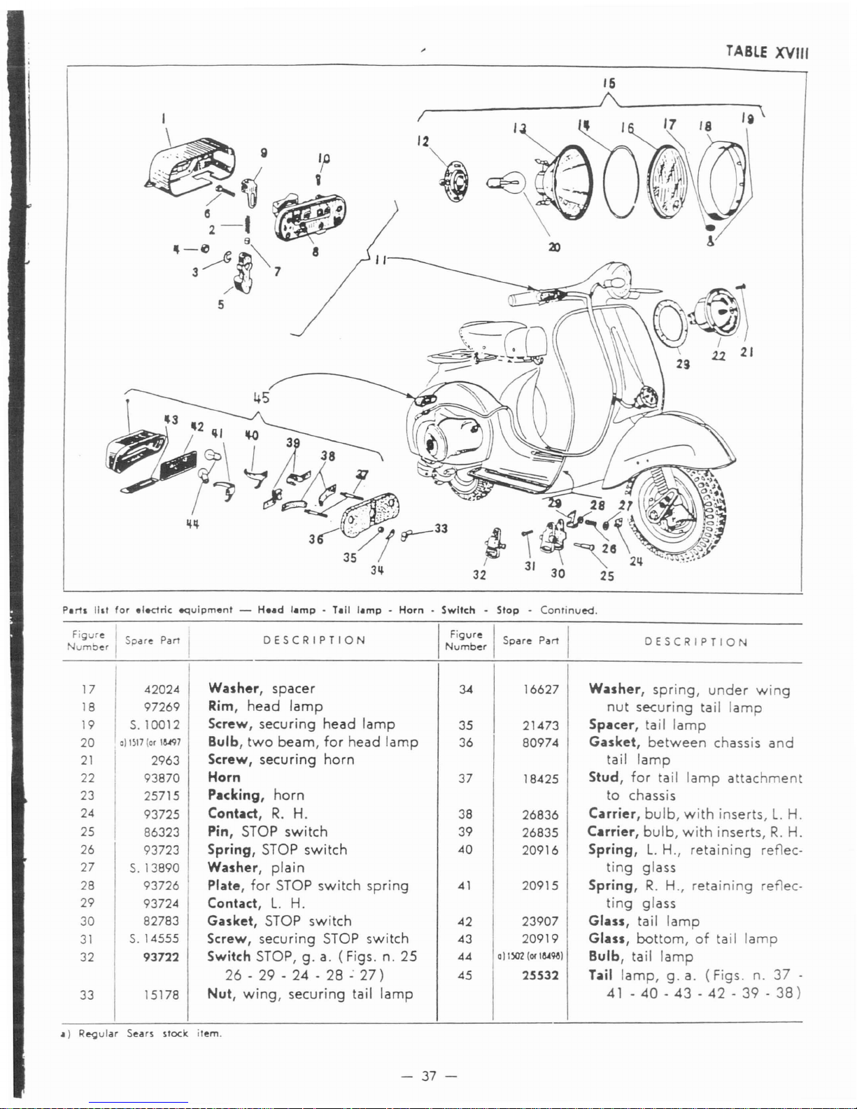
TABLE
XVIII
/5
,-
---~I\.'---------.,
/I
If
'i
I
\
~9
~~
/1~
e .
2-!
..,",'
~-~~~
3 . 7
/
5
Puts
11&1
(or
el.one
equipment
-
Head
lamp
- Tall
lamp-Horn-Switch-Stop-Continued.
F~~~:r
,
Spdfe
Part
IDE
S C
RIPTION
I
~~~~:r
I
Spare
Part
I
DESCRIPTION
17
42024
Washer,
spacer
34
16627
Wuher,
spring,
under
wing
18
97269
Rim,
head
lamp
nut
securing tail
lamp
19
S.10012
Screw,
securing
head
lamp
35 21473
Spacer,
tail lamp
20
al1517
(or
1~7
Bulb,
two
beam,
for
head
lamp
36 80974
Gasket,
between
chassis
and
21
I
2963
Screw, securing horn ta
il
lamp
22
93870
Horn
37
18425
Stud,
for tail
lamp
attachment
23
25715
Packing, horn
to chassis
24
93725
Contact,
R.
H.
38
26836
Carrier,
bulb,
with
inserts,
L.
H.
25
86323
Pin, STOP switch
39
26835
Curier,
bulb,
with
inserts,
R.
H.
26
93723
Spring,
STOP switch
40
20916
Spring,L.H.,
retaining
renee-
27
S.13890
Washer,
plain
ting glass
28
93726
Plate, for STOP switch spring
41
20915
Spring,
R.
H.,
retaining
renec-
29
93724
Contact,
L.
H.
ting glass
30
82783
Gasket,
STOP switch
42
23907
Glass,
tail lamp
31
S.14555
Screw, securing STOP switch 43
20919
Glass,
bottom,
of
tail lamp
32 93722
Switch STOP, g. a. (Figs. n. 25
44
all~
(01
laA9a)
Bulb, tail lamp
26
- 29 -
24-28.:27)
45 25532
Tail
lamp,g.a. (Figs.
n.
37
-
33
15178
Nut,
wing,
securing tail lamp
41-40-43-42-39-38)
.)
R~ular
Sears
sloek
item.
- 37 -
Page 38
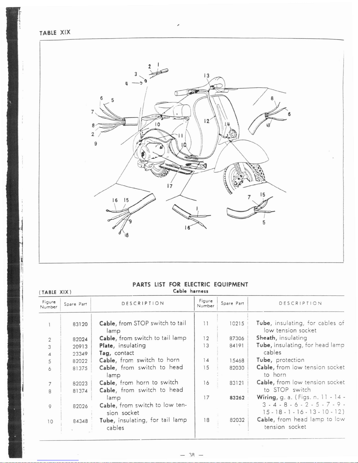
TABLE
XIX
\6
PARTS
LIST
FOR
ELECTRIC
EQUIPMENT
(TABLE
XIX)
C.ble
nuness
Figure I
DESCRIPTION
I
Figure
I
Spare
Part
DESCRIPTION
Num~r
Spare
Part
Number,
I
I
I
Cable,
from
STOP
switchtotail
I
Tube,
insulating,
for
cables
of
83120
11
10215 I
lamp
low
tension
socket
I
Cable,
from
switch
to tail
lamp
Sheath,
insulating
2
I
82024
12
87306
3
20913
Plate,
insulating
13
84191
Tube,
insulating,
for
head
lamp
4
23349
Tag,
contact
cables
5
82022
Cable,
fran:
switch
to
horn
14
15468
Tube,
protection
6
81375
Cable,
from
switch
to
head
15
82030
Cable,
from
low
tension
socket
lamp
to
horn
7
82023
Cable,
from
horn
to
switch
16
83121
Cable,
from
low
tension
socket
8
81374
Cable,
from
switch
to
head
to
STOP
switch
lamp
17
83262
Wiring,
g.a.(Figs.
n.11- 14 -
9
82026
Cable,
from
switch
to
low
ten-
3 - 4 - 8 - 6 . 2 - 5 - 7 - 9 -
sian
socket
15-18-1-16-13-10-12)
10
84348
Tube,
insulating,
for
tail
lamp
18
82032
Cable,
from
head
lamp
to
low
cables
tension
socket
-'/\-
Page 39

TABLE
XX
(TABLE
XX)
~
~
J
ft
j1
21
22
20
18
~
__
-~v
27
:~i~~~~-
==-~=:-=:--
:.:-
::.7'_-
-_._---
-----
l---."
~!i=-~~.--.!'~
I
II
PARTS
LIST
FOR
HAND
TOOLS,
SPEEDOMETER
AND
ACCESSORIES
Tool
kit·
Speedometer.
Spare
wheel
and
bracket
7
FigureISpare
Part
I
Number
DESCRIPTION
I
Figure
I I
Number
Spare
ParI
DESCRIPTION
2
3
4
5
6
7
8
9
83204
83202
83203
5.13920
5.
12113
93121
5.
13862
84741
Frame,
for
speedometer
glass
Glass,
for
speedorr.eter
Packing,
between
glass
and
frame
Ptlcking,
for
speedometer
hou-
-ing
Packing
Nut
Speedometer,
miles
(with
figs.
n. 2 - 3 - 1 - 4 - 6 -
5)
Washer,
stop,
on
fleXi
drive
Flex,
drive
(Figs.n.36-38
-
37 -
10)
10
11
12
13
14
15
16
17
18
19
9<4052
93113
5.3105
,
I
5.12490i
23969
5.13882
5.10018
I
11469 I
3202
.
82204 .
Cable,
flex
drive
with
washer
fig.
39
Support,
speedometer
Spring,
washer
Screw
Rubber
pad
Washer,
plain
Screw,
securing
speedo.
Roll, tool
Spanner,
box
(11
- 14 -21and
22
mm.)
Roll,
tool,
complete
(Figs.
n.
18-20-17-21
-22)
- 39 -
Page 40

Pinion,
drive
of
speedometer
Ring,
with
lubricator
Bush,
for
speedometer
drive
pinion
Ring,
biconical
-
Ring,
threaded,
for
sheath
Cap
Washer,
for
speedometer
cable
.--'
Rim,
g.
a.
(see
Table
XVII
Booklet
«Operating
instruc_
tions
and
parts
list
:.
Washer
>...
I
._-~:
~"
-
-'~'~
~-.
",t1
0,""
••c.111.,1
. '1 ....-
'
..
t'
:
f
•.
'.,
~.
,
~.
:
-',
~re
I
DESCRIPTION
I
Figure
!
Spare
Pan
Spare
Pan
Number
I
Number
I
20
3204
Screwdriver
30
2/17085
Spanner,
single
open
end
(7
I
21
17855
31
99938 I
mm.)
i
22
82199
Spanner,
double
open
end
(8
32
S.
13863
i
14
mm.)
Bolt
33
83973
23
S.14610
Washer,
spring
34
83883
24
S.3107
Bracket,
for
sparewheeI(wi
th
35 83880
25
872~
figs. n. 29 - 26 - 24 -
23)
Spacer
36
15718
26
85382
Bracket·
rim,
assy.
(Figs.
n. 25
37
80280
27
92209
30)
38
80279
28
85058
Measure,
for
fuel
mixture
39 94048
29
2814'
Nut
f
(
h.nd
tooll and
.".uorie,
-
Tool
kit·
Spe.dom.ter
. Sp4re
wh.el
and
brack.t
C:n
Inu~.
,..rt-a
lilt
0
 Loading...