

PHONIC ICON300, ICON700 User Manual
ICON300/ICON700
CONTRACTOR POWER AMPLIFIER
AMPLIFICADOR DE POTENCIA PARA CONTRATISTA
功率放大器
ICON300
ICON700
User’s Manual
Manual del Usuario
使用手册
English / Español / 简体中文

ICON300/ICON700
CONTRACTOR POWER AMPLIFIER
AMPLIFICADOR DE POTENCIA PARA CONTRATISTA
功率放大器
CONTENTS
Introduction.................................4
Features......................................4
Precautions.................................4
About This Manual......................4
Front Panel.................................5
Rear Panel.................................5
Balance Barrier Strip Input
Connections......................6
Barrier Strip Output
Connections.......................6
Audio Transformer Outputs.........6
CONTENIDO
Introducción......................................10
Características..................................10
Precauciones....................................10
Acerca de Este Manual..........................10
Panel Frontal.....................................11
Panel Trasero....................................11
Conexiones de Entrada Balanceada de
bornes de Seguridad.............12
Conexiones de Salida de los Bornes
de Seguridad.............................12
Salidas del Transformador de
目录
简介................................16
功能................................16
警示................................16
使用手册........................16
前面板............................17
背板................................17
平衡端子台输入
连接.......................18
端子台输出
连接.......................18
音频变压器输出..............18
Parallel Mono
Conguration.....................7
Specications..............................8
Block Diagrams.........................21
Phonic preserves the right to improve or alter any information within this document without prior notice
Phonic se reserva el derecho de mejorar o alterar cualquier información provista dentro de este documento sin previo aviso
Audio........................................12
Conguración Mono Paralelo............13
Especicaciones...............................14
Diagrama de Bloque.........................21
PHONIC保留不预先通知即可更新本文件的权利
并联MONO
设置.......................19
规格................................20
线路图............................21
V1.0 11/13/2008

1. Read these instructions before ope rat ing this
apparatus.
2. Keep these instructions for future reference.
3. Heed all warnings to ensure safe operation.
4. Follow all instructions provided in this document.
5. Do not use this apparatus near water or in locations
where condensation may occur.
6. Clean only with dry cloth. Do not use aerosol or liquid
cleaners. Unplug this apparatus before cleaning.
7. Do not block any of the ventilation openings. Install
in accordance with the manufacturer
’
s instructions.
8. Do not install near any heat sources such as radiators,
heat registers, stoves, or other apparatus (including
.
9. Do not defeat the safety purpose of the polarized or
grounding-type plug. A polarized plug has two blades
with one wider than the other. A grounding type plug
has two blades and a third grounding prong. The wide
blade or the third prong is provided for your safety. If
the provided plug does not into your outlet, consult
an electrician for replacement of the obsolete outlet.
10. Protect the power cord from being walked on or
pinched particularly at plug, convenience receptacles,
and the point where they exit from the apparatus.
11. Only use attachments/accessories by the
manufacturer.
12. Use only with a cart, stand, tripod, bracket, or
table by the manufacturer, or sold with
the apparatus. When a cart is used, use caution
wh en mo ving the cart /appa rat us
combination to avoid injury from tipover.
13. Unplug this apparatus during lighting
storms or when unused for long
periods of time.
14. Refer all servicing to service personnel.
Servicing is required when the apparatus has been
damaged in any way, such as power-supply cord or
plug is damaged, liquid has been spilled or objects
have fallen into the apparatus, the apparatus has
been exposed to rain or moisture, does not operate
normally, or has been dropped.
IMPOrTaNT SafETY INSTruCTIONS
CAUTION: TO REDUCE THE RISK OF ELECTRIC SHOCK,
DO NOT REMOVE COVER (OR BACK)
NO USER SERVICEABLE PARTS INSIDE
REFER SERVICING TO QUALIFIED PERSONNEL
The lightning flash with arrowhead symbol, within an
equilateral triangle, is intended to alert the user to the
presence of uninsulated
“
dangerous voltage
”
within the
product
’
magnitude to constitute a risk of electric shock to persons.
The exclamation point within an equilateral triangle is in-
tended to alert the user to the presence of important operat-
ing and maintenance (servicing) instructions in the literature
accompanying the appliance.
WarNING: To reduce the risk of or electric shock, do
not expose this apparatus to rain or moisture.
CauTION: Use of controls or adjustments or performance
of procedures other than those may result in
hazardous radiation exposure.
The apparatus shall not be exposed to dripping or splashing and that no objects with liquids, such as vases,
shall be placed on the apparatus. The MAINS plug is used as the disconnect device, the disconnect device shall
remain readily operable.
Warning: the user shall not place this apparatus in the area during the operation so that the mains switch
can be easily accessible.
CauTION
rISK Of ElECTrIC ShOCK
DO NOT OPEN

4 ICON 300/700
INTrODuCTION
Congratulations on your purchase of the Phonic Icon 300 or 700
power amplier. The Icon Series is a line of professional power
ampliers specically designed for contracting application.
These two models each has independent channels and is
available for driving 200V, 140V, 100V, 70V, 50V or 25V
"constant voltage" lines. Each channel has its own power
transformer (toroidal type) secondary to provide maximum audio
separation (minimum sound leakage) between two channels,
minimizing interaction that can otherwise occur on ampliers
with a common power supply.
fEaTurES
● Automatic dual-speed, high efciency fan cooling
● Rear panel detented gain controls for security and
resetability
● Stereo, bridge or parallel operating modes
● XLR and barrier strip inputs
● XLR in and outs for multiple amplier operation & easy
signal pass-through
● Fully short-circuit, temperature and DC offset protection
● Barrier strip connection determines output mode - 25V, 70V,
100V and direct outputs available simultaneously
● Toroidal output transformers provide full electrical isolation
and meet worldwide safety agency approval
● Built-in 45 Hz subsonic lter prevents speaker transformer
saturation with minimal effect on program material
● Power-up muting
PrECauTIONS
1. When rst powering up the amp, keep the amplier gain
controls all the off, in order to block potentially damaging or
annoying sounds caused by defective cables or hookups.
When turning up the gain, do it gradually, until normal
operation is veried. These precautions are necessary with
all high-power ampliers, since they have enough power to
blow most speakers in abnormal situations.
2. Check the AV Voltage before connecting the AC plug
3. Speaker Output Shock Hazard! The Icon 300 and 700 amps
are capable of producing hazardous output voltages. To
avoid electrical shock, make sure the cover is in place over
the output terminals, and do not touch any exposed speaker
wiring while the amplier is operating.
abOuT ThIS MaNual
Please be reminded that a power amplier is a high-current,
high-power device and should be treated with respect and care.
Please read this manual before connecting and operating your
unit, and le it in a safe place for future reference.

Front Panel DescriPtion
+ - 0 70 100
1. Power switch
The power ON/OFF switch with an LED indicator.
2. Protect leD indicator
The Icon 300/700 features several types of protection to prevent
damage to the circuitry during turn-on or fault conditions. If the
LEDs light up, this indicates that one of the various protections
is safeguarding the different sections of the amplier and in
these cases, the power output is normally switched off until
normal operating conditions are restored.
Loudspeaker protection: the power-on protection relay
prevents damaging thumps to the speakers as the power
comes on. When the amp is switched on, the protect LED
will light for a few seconds, and then go out, indicating that
the relay has closed.
Thermal protection on the heat sink: If the amp overheats,
thermal shutdown protects the circuitry until the temperature
is reduced to a safe level.
Short circuit protection: The Protect LED Indicator will also
light up if the speaker terminals are short-circuited, or the
impedance of the load is too low. In these circumstances,
the Protect LED will stay on until the fault conditions are
rectied.
Some protection situations require the amplier to be
switched off and then back on for normal operating
conditions to be restored.
3. clip leD indicator (icon 300)
The LEDs light up at clipping status, whenever any conditions
occur that could cause problems for the amp, such as an outof-spec load and waveform distortion. Because of the Icon's
ability to enter and exit clipping with as few audible artifacts as
possible, you may not hear any distortion even if the indicator
ashes. In general, a few ashes every now and then will not be
a problem. However, if the LEDs ash often or remain on for any
extended period of time, then turn down the volume controls
to reduce the signal level going to the Icon amp. If this doesn't
solve the problem, check your output cables and speakers.
4.Signal “Status” LED Indicator
Each channel of the Icon 300/700 features a signal LED to show
that there is an audio signal at the input to the channel. The
threshold for the indicator is -26dB, which should be enough to
avoid noise triggering the LED.
5. limit leD indicator (icon 700)
The Icon 700 has a built-in limiter on each channel to prevent
clipping. Should the signal reach a level high enough to cause
clipping (ie. output power is over 400W per channel), the limiter
momentarily reduces the input signal level, just enough to
prevent it. The limit LED lights whenever this occurs.
rear Panel DescriPtion
6. Gain controls
These two knobs and the level controls for channels one and
two respectively. Turning clockwise will increase its gain and
counter clockwise will decrease its gain. Please always powerup with the volume all the way down, and increase the volume
slowly to make sure that no conditions exist which could annoy
your audience or harm your speakers.
7. cH1/cH2 inputs (Xlr connectors)
These inputs are provided for making balanced connection to
mixers, preamps, etc. The XLR inputs are wired as per the
following convention:
8. Balanced Barrier strip inputs
These connection points provide the best option for permanent
or long-term installation. Connections should be screwed down
tight to exclude oxygen, and care should be taken to avoid loose
strands of wire that may cause short circuits.
9. CH1/CH2 Parallel Pass Through XLR Connectors
These XLR output connectors are provided for parallel
connection to another Icon or other amplier.
10. Stereo/Parallel/Bridge Switch
In stereo operation, two separate signals are treated separately
by channels 1 and 2 of the ampliers.
In Parallel operation, one signal is treated by bother channel
1 and 2 of the amplier. In other words, a signal connected to
Input CH1 (6) or CH2 (7) is sent to both Output CH1 (10) and
CH2 (11).
In Bridge operation, both channels are congured to drive a
single load with a single signal to CH1 (only CH1 is operative,
and CH2 input must be vacant) at twice the power.
This switch should only be used when the Amplier is off;
otherwise the speakers' components could be damaged.
11. Direct output connectors, cH1/cH2
These are barrier strips to connect low impedance speakers.
Spade lugs and bare wires should both be screwed down tight
to exclude oxygen, and care should be taken to avoid loose
strands of wire that may cause short circuits.
12. audio transformer outputs, cH1/cH2
These are barrier strips to connect distributed line (25V, 70V,
100V, 140V and 200V). Spade lugs and bare wires should both
be screwed down tight to exclude oxygen, and care should
be taken to avoid loose strands of wire that may cause short
circuits.
5ICON 300/700

6 ICON 300/700
banlance barrier Strip Input Connections
Balanced connection - Attach as shown. Connect the (+) wire
and ground wire to terminal pins as marked.
Direct low impedance:
Unbalanced connection - Attach input signal wires as shown.
Use the non-inverting (+) input and the ground terminals of the
header, and also connect a wire jumper between the inverting
(-) input and the ground terminal. The wire jumper will prevent a
reduction in gain caused by a oating unbalanced input.
Input sensitivities - - Audio signals of these levels will produce
full rated output power at 8 ohms.
ICON 300 - 1.02Volts (+2.4dbu)
ICON 700 - 1.02Volts (+2.4dbu)
barrier Strip Output Connections
Barrier strips located on the rear panel allow speaker cable
connections to the amplier output. See the diagrams for
details on connecting speakers and/or distributed (23-, 70-,
or 100-volt) lines. Insulated connectors of the type shown are
recommended.
Always make sure the amplier is turned off before you
change any output connections.
Output connection for Icon 300/700,
bridge mono mode
Output connection for Icon 300/700,
direct low impedance
Bridge Mono Conguration for Direct Outputs
1. Set into bridge mode
2. Connect the signal to channel 1's input only. Do not
connect an input signal to channel 2.
3. Use on channel 1's gain control to set the level. Both
channels' signal and clip indicators should ash identically
when the amplier is operating.
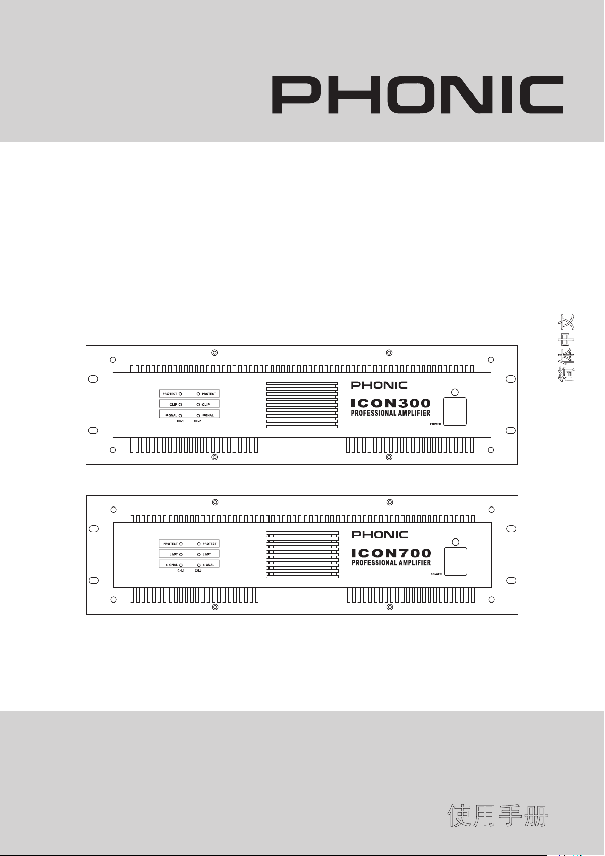
audio Transformer Outputs
Make sure the sum of the power settings of all the speakers
does not exceed the power rating of the amplier. It is a good
practice to allow a 20% safety margin. For example, if the
amplier has a power rating of 300W, it is always a good idea to
make sure the sum of the loudspeaker loads on the distributed
line is 240W or less.
25 volt line output connection
Loose screw terminals, insert wire connectors under screws.
Tighten screw terminals.
50 volt line output connection
100 volt line output connection
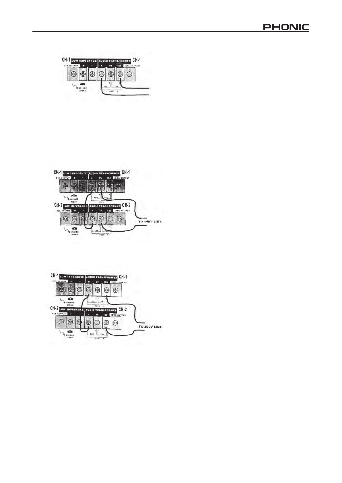
Bridge Mono Conguration for Audio Transformer Outputs
1. For driving 140V or 200V distributed lines, the amplier must
be set into bridge mono mode.
2. Connect the signal to channel 1's input only. Do not
connect an input signal to channel 2.
3. Use only channel 1's gain control to set the level. Both
channels signal and clip indicators should ash identically
when the amplier is operating.
Parallel Mono Conguration
The "Parallel mode" ties the two channel inputs together so
that both are driven by the same signal, without the need for
external jumpers or wiring. After the inputs, both channels
operate independently. Though they carry the same signal, their
gain controls affect only their respective channels, which must
be used separately. Please refer to the previous Rear Panel
Description. Never parallel the speaker outputs.
Low-Impedance and Distributed Speakers on Icon
Ampliers
If your application calls for connection of an 8 ohm speaker and
a distributed line to the same amplier channel, the Icon 300
and Icon 700 are among the very few ampliers that can do
that. However, since most of the audio power is drawn by the
direct-connected speaker, you must derate the distributed line;
and the distributed line should have a total power load of no
more than one-fourth of the ampliers normal distributed line
power rating.
Computing maximum allowable distributed line load with a
known low-impedance load
MaxTOP = [MaxRatedPL - ((2 x MaxRatedPL)/Impedance)]/2
MaxTOP is the sum of the power taps of the speakers connected
to the Audio Transformer outputs.
MaxRatedPL is the maximum rated power of the amplier into
a two ohm load.
Impedance is the load impedance connected to the direct
outputs.
Example: One channel of an Icon 700 has an 8-ohm load
connected to the Direct (low impedance) output. Then the
maximum power left available to drive a distributed line is:
140 volt line output connection,
bridge mono mode
200 volt line output connection,
bridge mono mode
MaxTOP = [550-((2x550/8)/2)] = 206 Watts
7ICON 300/700

Specications
ICON 300 ICON 700
Direct Power Out
Max.average power at 45Hz-20kHz
With 0.1% THD
8 ohm 120W×2 240W×2
4 ohm 200W×2 400W×2
2 ohm,1kHz,1%THD 300W×2 550W×2
Bridged mono 8 ohm,1kHz,1%THD 420W 850W
Bridged mono 4 ohm,1kHz,1%THD 540W 1100W
Isolated Constant Voltage Out
200V or 140V Bridege 300W 700W
100V or 70V 150W×2 350W×2
25V 120W 280W×2
frequency response
Direct Outputs (+0/-2dB) 50Hz-50kHz
Isolated Outputs (+0/-2dB) 50Hz-16kHz
Total harmonic Distortion <0.05 <0.05
Sensitivity (fro full output) 1.02V 1.02V
Voltage Gain 28dB 32dB
Input Impedance
Balanced/Unbalanced 20k/10k ohm
Damping factor >200(direct output)
S/N ratio Less than 100dB below rated output (20Hz-20kHz)
Output offset voitage protection
Protection Circuits
Controls
Front Panel Power Switch
Rear Panel Ch1 & Ch2 gain controls (41 click); Parallel/Stereo/Bridge switch
Connectors
Input XLR jack ×2,Barrier strip ×1
Output Covered Barrier strip ×2;heavy-duty binding post
Cooling One dual speed fan
Indicators
Dimensions(h×W×D) 132×480×428mm 132×480×428mm
Net Weight 24.3KG 24.3KG
Shipping Weight 26.0KG 26.KG
Clip:Red Signal:Green Pro-
tect:Yellow Power:Red
Heat sink overheat protection
Transformer overheat protection
Load shorting protection
Power on/off protection
Limit:Red Signal:Green Pro-
tect:Yellow Power:Red
8 ICON 300/700
 Loading...