

Page 1
iAMP 1620
iAMP 3020
User's Manual
Manual del Usuario
Page 2

iAMP1620 / iAMP3020
DIGITAL AMPLIFIER
AMPLIFICADOR DIGITAL
ENGLISH .....................................I
ESPAÑOL .....................................II
V1.3 07/27/2012
iAMP 1620
iAMP 3020
English Español
Page 3

3
iAMP1620 / iAMP3020
English
INTRODUCTION 1
FEATURES 1
FRONT PANEL 1
BACK PANEL 2
SPECIFICATIONS 3
APPENDIX
APPLICATIONS 1
DIMENSIONS 2
BLOCK DIAGRAMS 3
CONTENTS
USER'S MANUAL
Phonic preserves the right to improve or alter any information within this
document without prior notice
Page 4

4
iAMP1620 / iAMP3020
English
1. Read these instructions before operating t his
apparatus.
2. Keep these instructions for future reference.
3. Heed all warnings to ensure safe operation.
4. Follow all instructions provided in this document.
5. Do not use this apparatus near water or in locations
where condensation may occur.
6. Clean only with dry cloth. Do not use aerosol or liquid
cleaners. Unplug this apparatus before cleaning.
7. Do not block any of the ventilation openings. Install
in accordance with the manufacturer
’
s instructions.
8. Do not install near any heat sources such as radiators,
heat registers, stoves, or other apparatus (including
.
9. Do not defeat the safety purpose of the polarized or
grounding-type plug. A polarized plug has two blades
with one wider than the other. A grounding type plug
has two blades and a third grounding prong. The wide
blade or the third prong is provided for your safety. If
the provided plug does not
into your outlet, consult
an electrician for replacement of the obsolete outlet.
10. Protect the power cord from being walked on or
pinched particularly at plug, convenience receptacles,
and the point where they exit from the apparatus.
11. Only use attachments/accessories
by the
manufacturer.
12. Use only with a cart, stand, tripod, bracket, or
table
by the manufacturer, or sold with
the apparatus. When a cart is used, use caution
when moving the cart/apparatus
combination to avoid injury from tipover.
13. Unplug this apparatus during lighting
storms or wh en unused for long
periods of time.
14. Refer all servicing to
service personnel.
Servicing is required when the apparatus has been
damaged in any way, such as power-supply cord or
plug is damaged, liquid has been spilled or objects
have fallen into the apparatus, the apparatus has
been exposed to rain or moisture, does not operate
normally, or has been dropped.
IMPORTANT SAFETY INSTRUCTIONS
CAUTION: TO REDUCE THE RISK OF ELECTRIC SHOCK,
DO NOT REMOVE COVER (OR BACK)
NO USER SERVICEABLE PARTS INSIDE
REFER SERVICING TO QUALIFIED PERSONNEL
The lightning flash with arrowhead symbol, within an
equilateral triangle, is intended to alert the user to the
presence of uninsulated
“
dangerous voltage” within the
product
’
magnitude to constitute a risk of electric shock to persons.
The exclamation point within an equilateral triangle is in-
tended to alert the user to the presence of important operat-
ing and maintenance (servicing) instructions in the literature
accompanying the appliance.
WARNING: To reduce the risk of or electric shock, do
not expose this apparatus to rain or moisture.
CAUTION: Use of controls or adjustments or performance
of procedures other than those
may result in
hazardous radiation exposure.
The apparatus shall not be exposed to dripping or splashing and that no objects
with liquids, such as vases,
shall be placed on the apparatus. The MAINS plug is used as the disconnect device, the disconnect device shall
remain readily operable.
Warning: the user shall not place this apparatus in the
area during the operation so that the mains switch
can be easily accessible.
CAUTION
RISK OF ELECTRIC SHOCK
DO NOT OPEN
Page 5
1
iAMP1620 / iAMP3020
English
INTRODUCTION
Congratulations on your purchase of another great Phonic product.
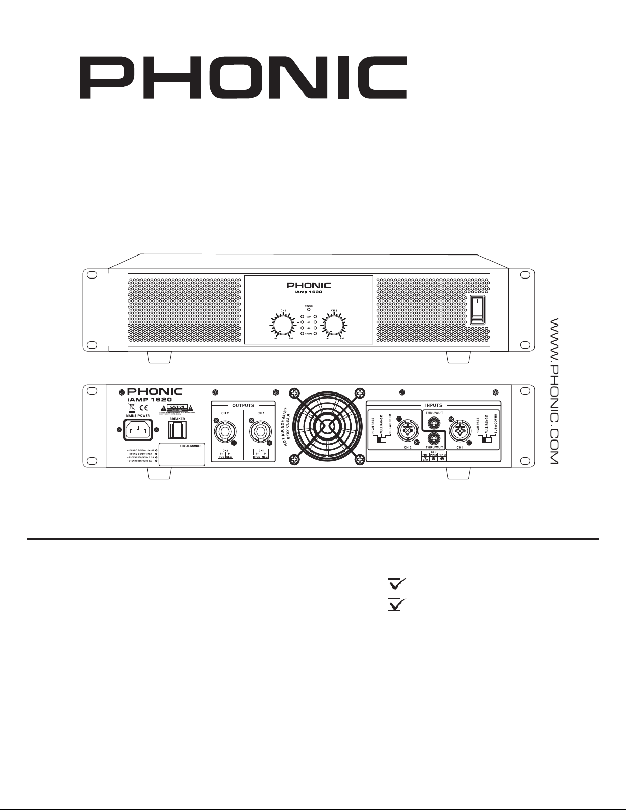
The iAMP1620 and iAMP3020 were carefully designed so as to
provide phenomenal power in a low-weight, easily-manageable
construction that is rack-mountable. Phonic combines its revolu-
tionary D-class amplier technology with stable, reliable power
supplies for fantastic amplication even under the most rigorous
of conditions.
Various operation modes are available on each channel, providing users with an easy way to use the iAMP with subwoofers or
mid-high frequency speakers without additional gear. Combination inputs were included allowing for more versatile input, while
professional-standard speakon output connectors are included for
connection to speakers. The iAMP further offers ¼” thru jacks to
daisy-chain the input signal into further ampliers.
We know how eager you are to get started – getting the amp out
and hooking all your gear up is probably your number one priority right now – but before you do, we strongly urge you to take
a look through this manual. Inside, you will nd important facts
and gures on the set up, use and applications of your brand
new iAMP. Remember that safe operation of an amplier is of the
utmost importance, so we strongly recommend that users heed
all warnings and instructions listed in this manual.
FEATURES
• Each channel runs 1600 or 3000 Watts of power into 2 ohms
• Innovative class D amplication circuitry
• Independent fourth-order Linkwitz-Riley crossover
• Convenient combo jacks accepting ¼” and XLR inputs
• Detented front panel input gain controls
• Independent ¼” thru jacks for expanded operation
• 4 pole professional speaker twist lock outputs
• Full range of safety circuits for full protection
FRONT PANEL
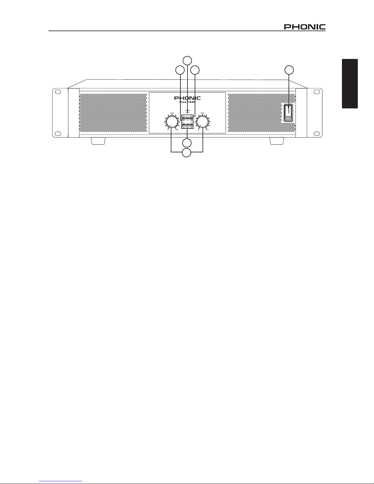
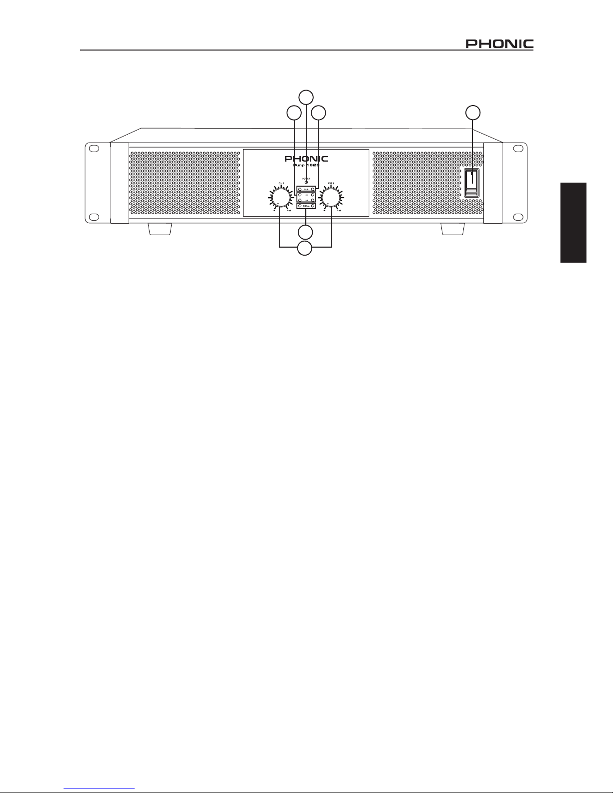
1. Gain Controls
These controls adjust the incoming level received by the respective channel 1 and channel 2 input jacks on the rear of the iAMP.
It is idea to set these controls to the right-most position to allow
optimal use of the incoming signal whenever possible.
2. Signal LED
These LED indicators will light up whenever the iAMP produces a
signal through the corresponding input channels, equal to about
4 volts RMS.
3. Level LEDs
These LEDs will illuminate when the output level of the iAMP
reaches the levels indicated, -20 and -10 dB. For best results,
set the Gain controls to a level that lets the -20 indicator ash
steadily.
4. Clip LED
The Clip LED will light up just prior to the clipping of the output
signal, giving users a clear way to know whether to lower the
Gain controls to reduce the outgoing signal. A steady ashing or
constant illumination will require attention by the user, whereas an
occasional ash doesn’t necessarily indicate immediate issues.
5. Power LED
This LED will light up when the iAMP is turned on.
6. Power Switch
This switch is used to activate and deactivate the iAMP. Be sure
to power on all input devices, including mixers and/or signal processors before turning the iAMP on, and ensure the iAMP is the
rst device you turn off.
2
1
3
6
5
4
Page 6

2
iAMP1620 / iAMP3020
English
BACK PANEL
7. Combo Input Jacks
Both channels of the iAMP offer actively balanced ‘combination’
input jacks. These accept either 3-pin XLR or ¼” TRS connectors.
The design of the iAMP’s circuitry allows for the highest possible
input signal level to be received from the majority of sources.
8. Channel Mode Switch
This switch allows the users to select from three operation
modes.
High Pass: This position will activate a high-pass lter on the
corresponding channel. This is a Linkwitz-Riley lter that will cut
all frequencies below 100 Hz. This is ideal for use when additional
subwoofer cabinets will be used in the setup, allowing the ampli-
er to concentrate on signals above 100 Hz for use with mid-high
frequency speakers.
Full Range: This position will allow all frequencies to pass through
the amplier; high, mid and low. This setting will typically be used
when full-range speakers are connected to the iAMP.
Subwoofer: Selecting this position on the Channel Mode Switch
will allow all frequencies below 100 Hz to pass through the amplier. Again, this is a Linkwitz-Riley lter. This position is ideal for
use with dedicated subwoofer speakers, allowing the amplier to
concentrate on these frequencies and thus improving the level of
bass and your overall ‘thump’.
9. Thru Output
These balanced ¼” outputs allow users to patch the incoming
signals directly out to additional ampliers or input devices.
10. Speaker Connectors
The iAMP offers a professional-standard 4 pole speaker connector
for each output channel. Twist the cable clockwise to lock speakers
into place and counter clockwise to release.
11. Breaker Switch
In the unlikely event that an external inuence posses an issue
that could potentially harm the unit, the iAMP’s breaker will trip.
Check all wiring and cables before resetting a tripped breaker. If
the breaker trips again, it would be advisable to get in touch with
your country’s Phonic distributor for repairs and services.
12. AC Power Connector
This input connector is for IEC power cables, allowing for AC power
to be sent to the unit. Please use the power cable provided with
the unit to power the iAMP. We strongly suggest that you under no
circumstances remove the grounding pin from the cable. Doing so
could be detrimental to the iAMP’s operation and to your safety.
13. Cooling Fan
Due to the heat that can be accumulated when amplifying signals,
Phonic includes a variable-speed fan that is temperature sensitive
– activated and deactivating as necessary.
10
7
8
8
9
12
13
11
Page 7

3
iAMP1620 / iAMP3020
English
SPECIFICATIONS
iAMP 1620 iAMP 3020
1KHz, 0.5% THD
Output Per Channel
Output Power 8 ohms 600W 1200W
Output Power 4 ohms 1060W 2000W
Output Power 2 ohms 1600W 3000W
Input Sensitivity
0.775 volts +/- 3% for 1 kHz 4 ohm rated power,
0.68 volts +/- 3% for 1 kHz. 2 ohm rated power
Input Connector One Combo Jack (XLR+1/4") per channel
Signal Through Out One 1/4" phone jack per channel
Frequency Response 10Hz – 50KHz
Speaker Output One Speakon connector per channel
Built-in Filters High-Pass, Sub-woofer, switchable
S/N Ratio (20 Hz – 20 KHz) > 105dB A-Weighted
THD@ 1 kHz (10% Rated Output) Less than 0.1%
Protection Circuitry
Multiple Protection designs against DC bias,
thermal fault, load mismatch, etc.
Power Consumption 800W 2Ω LOAD STEREO 1500W 2Ω LOAD STEREO
Dimensions (WxHxD) 483 x 105 x 415 mm (19.02" x 4.13" x 16.34")
Weight 6.1 kg (13.4 lbs) 6.8 kg (14.9 lbs)
Page 8

iAMP1620 / iAMP3020
4
iAMP1620 / iAMP3020
English
SERVICE AND REPAIR
For replacement parts, service and repairs please contact the Phonic distributor in your
country. Phonic does not release service manuals to consumers, and advice users to not
attempt any self repairs, as doing so voids all warranties. You can locate a dealer near you at
http://www.phonic.com/where/.
WARRANTY INFORMATION
Phonic stands behind every product we make with a no-hassles warranty. Warranty coverage
may be extended, depending on your region. Phonic Corporation warrants this product for a
minimum of one year from the original date of purchase against defects in material and
workmanship under use as instructed by the user’s manual. Phonic, at its option, shall repair
or replace the defective unit covered by this warranty. Please retain the dated sales receipt as
evidence of the date of purchase. You will need it for any warranty service. No returns or repairs
will be accepted without a proper RMA number (return merchandise authorization). In order to
keep this warranty in effect, the product must have been handled and used as prescribed in the
instructions accompanying this warranty. Any tampering of the product or attempts of self repair
voids all warranty. This warranty does not cover any damage due to accident, misuse, abuse,
or negligence. This warranty is valid only if the product was purchased new from an authorized
Phonic dealer/distributor. For complete warranty policy information, please visit
http://www.phonic.com/warranty/.
CUSTOMER SERVICE AND TECHNICAL SUPPORT
We encourage you to visit our online help at http://www.phonic.com/support/. There you can find
answers to frequently asked questions, tech tips, driver downloads, returns instruction and other
helpful information. We make every effort to answer your questions within one business day.
support@phonic.com
http://www.phonic.com
Page 9

5
iAMP1620 / iAMP3020
English Español
iAMP1620 / iAMP3020
CONTENIDO
Manual del Usuario
Phonic se reserva el derecho de mejorar o alterar cualquier información
provista dentro de este documento sin previo aviso.
INTRODUCCIÓN 1
CARACTERÍSTICAS 1
PANEL FRONTAL 1
PANEL POSTERIOR 2
ESPECIFICACIONES 3
APÉNDICE
APLICACIONES 1
DIMENSIONES 2
DIAGRAMAS DE BLOQUE 3
Page 10

6
iAMP1620 / iAMP3020
English Español
Page 11
1
iAMP1620 / iAMP3020
English Español
INTRODUCCIÓN
Felicitaciones por la compra de otro fantástico producto de
Phonic. Los iAMP1620 y iAMP3020 han sido meticulosamente
diseñados para brindarle una potencia fenomenal en peso liviano,
construcción fácil administrable de rack montable. Phonic combina
su tecnología revolucionaria de amplicadores clase D con un
suministro de potencia able para excelente amplicación bajo
las condiciones más rigurosas.
Varias operaciones de modo están disponibles en cada canal
ofreciendo a los usuarios con una facilidad de uso del iAMP con
subwoofers o altavoces de frecuencia media-alta sin dispositivos
extras. La combinación de entradas ha sido incluida para entradas
más versátiles, con conectores profesionales estándar speakon
que incluyen para más conexiones de altavoces. Los iAMP ofrecen
¼” jacks para enlazar entrada de señal a más amplicadores.
Sabemos que usted está ansioso de comenzar el uso de dicha
unidad- antes de comenzar el encablado y salida de amp de todo
su equipo es probablemente unas de las prioridades ahora-pero
antes de hacer tales procesos, le sugerimos que lea este manual.
Dentro usted, encontrará información importante y guras sobre
la instalación, usos y aplicaciones para su nuevo iAMP. Recuerde
que la operación segura de un amplicador es lo más importante,
así que le recomendamos hacer caso a las advertencias e instrucciones listadas en este manual.
CARACTERÍSTICAS
• Cada canal ejecuta 1600 Watts o 3000 Watts de potencia a 2 ohms
• Circuito innovador amplicador clase D
• Crossover independiente de cuarta orden Linkwitz-Riley
• Conveniente combo jacks aceptando entradas ¼” y XLR
• Fijador de controles de ganancia en el panel frontal
• Independiente ¼” mediante jacks para ampliar operaciones
• 4 polos twist lock de salida para altavoces profesionales
• Gama completa de protección para circuitos de seguridad
PANEL FRONTAL
1. Ganancias de Controles
Estos controles ajustan los niveles de entrada recibidos por las
entradas jacks del panel posterior del iAMP del respectivo canal
1 y canal 2. Es la idea de congurar estos controles a la posición
más correcta para tener un uso óptimo de las señales de entrada
posibles.
2. Señal LED
Los indicadores LED se iluminarán cuando el iAMP produzca
una señal mediante la entrada de canal correspondiente, igual a
o igual 4 volts RMS.
3. Nivel de LED
Estos LED se iluminarán cuando los niveles de salida del iAMP
llegue al nivel indicado, -20 y -10 dB. Para mejores resultados,
congure los controles de Ganancia a un nivel que deje a los
indicadores ash de -20 rmes.
4. Clip LED
El Clip LED se iluminará solo antes que del recorte de la señal de salida,
ofreciendo a los usuarios una manera clara de cómo bajar los controles
Ganancia en reducir la salida de canales. Un ash rme o constante
iluminación requerirá la atención del usuario, donde en ocasiones el
ash no es necesariamente indica cuestiones inmediatas.
5. Power LED
Este LED se iluminará cuando el iAMP está activado.
6. Interruptor de Potencia
Este interruptor es usado para activar y desactivar el iAMP.
Asegúrese de encender todas las entradas de los dispositivos
incluyendo mezcladoras y/o procesadores de señal antes de
encender el iAMP, y asegure de que el iAMP es primer dispositivo
que usted apague.
2
1
3
6
5
4
Page 12

2
iAMP1620 / iAMP3020
English Español
PANEL POSTERIOR
7. Combo de entradas Jacks
Ambos canales del iAMP ofrece combinación activa balanceada de
entradas jack. Estas aceptan un 3-pin XLR o conectores ¼” TRS.
El diseño del circuito del iAMP permite posibles entradas de señal
de nivel alto a ser recibidos desde las fuentes principales.
8. Interruptor para Modo de Canal
Este interruptor permite a los usuarios en seleccionar tres modos
de operaciones.
Paso-Alto (High Pass): Esta posición activará un ltro de paso
alto en los canales correspondientes. Este ltro de Linkwitz-Riley
cortará todas las frecuencias bajo 100 Hz. Es ideal para los usos
de gabinetes de subwoofer adicionales en ser usados en las
instalaciones, permitiendo que los amplicadores se concentren
en las señales sobre 100 Hz para usos de altavoces de frecuencia
media-alta.
Gama-Completa: Esta posición permitirá que todas las frecuen-
cias pasen mediante el amplicador; alto, medio y bajo. Esta
conguración será empleado típicamente cuando los altavoces
estén a gama completa conectados al iAMP.
Subwoofer: Seleccione esta posición en el interruptor de Modo
del Canal que le permitirá todas las frecuencias bajo 100Hz a
pasar mediante el amplicador. Nuevamente, este es un ltro
Linkwitz-Riley. Esta posición es ideal para usos con altavoces
subwoofer dedicados, permitiendo al amplicador a concentrarse
en estas frecuencias y mejorar el nivel de bass en su todo su
¨thump¨(golpe seco).
9. Mediante Salida
Estas salidas balanceadas ¼” permite a los usuarios en parchar
las señales entrantes directo a la salida a amplicadores adicionales o entradas de dispositivos.
10. Conectores de Altavoz
El iAMP ofrece un conector de altavoz profesional estándar de 4
polos para cada salida de canal. El torcido del cable en dirección
en sentido a las agujas del reloj para cerrar los altavoces en lugar
y en sentido contrario para liberarlo.
11. Disyuntor ( Breaker Switch)
En un evento de caso poco probable una inuencia externa
posee una cuestión que puede dañar potencialmente la unidad,
los disyuntores del iAMP se activarán. Revise todo los encabla-
dos y cables antes de re-congurar un disparador disyuntor. Si
el disyuntor es activado nuevamente, le sugerimos en que se
ponga en contacto con su distribuidora Phonic de su país para
reparaciones y servicios.
12. Conector de Potencia AC
Esta entrada de conector es para cables de potencia IEC, permitiendo que la potencia AC sea enviada a la unidad. Favor de usar
el cable de potencia que viene con la unidad para potenciar el
iAMP. Le recomendamos que bajo ninguna circunstancia remueva
la varada (grounding pin) del cable. En hacer esto eliminará la
seguridad operativa de su iAMP.
13. Ventilador
El calor acumulado durante las amplicaciones de señales, Phonic
ha incluído un ventilador de velocidad variable que es sensitivo a la
temperatura que será activa y desactivada al ser necesitado.
10
7
8
8
9
12
13
11
Page 13

3
iAMP1620 / iAMP3020
English Español
ESPECIFICACIONES
iAMP 1620 iAMP 3020
1KHz,0.,5%THD
Salida por Canal
Salida de Potencia 8 ohms 600W 1200W
Salida de Potencia 4 ohms 1060W 2000W
Salida de Potencia 2 ohms 1600W 3000W
Entrada de sensibilidad
0.775 voltios +/- 3% por 1 kHz 4 ohm potencia nominal,
0.68 voltios +/- 3% por 1 kHz. 2 ohm potencia nominal
Entrada de Conector Un Combo jack/ cada Canal
Señal mediante Salida 1x1/4" phone jack/ Canal
Respuesta de Frecuencia 10Hz – 50KHz
Salida de Altavoz Un Speakon cada Canal
Filtros Integrados Paso Alto, Subwoofer intercambiable
S/N Relación (20Hz-20KHz) 105dB Ponderación-A 20Hz-20KHz
THD@ 1 kHz (10% Salida Nominal) Menos de 0.1%
Circuito de Protección Diseños de Múltiple Protección contra DC sesgo, falla deTermal, Carga de desajustada, ect.
Potencia de Consumo 800W 2Ω CARGA ESTÉREO 1500W 2Ω CARGA ESTÉREO
Dimensiones (An x Alt x P),mm 483 x 105 x 415 mm (19.02" x 4.13" x 16.34")
Peso 6.1 kg (13.4 lbs) 6.8 kg (14.9 lbs)
Page 14

4
iAMP1620 / iAMP3020
English Español
SERVICIO Y REPARACIÓN
Para refacciones de reemplazo y reparaciones, por favor póngase en contacto con nuestro
distribuidor de Phonic en su país. Phonic no distribuye manuales de servicio directamente a los
consumidores y, avisa a los usuarios que no intenten hacer cualquier reparación por si mismo,
haciendo ésto invalidará todas las garantías del equipo. Puede encontrar un distribuidor cerca
de usted en http://www.phonic.com/where/.
INFORMACIÓN DE LA GARANTIA
Phonic respalda cada producto que hacemos con una garantía sin enredo. La cobertura de
garantía podría ser ampliada dependiendo de su región. Phonic Corporation garantiza este
producto por un mínimo de un año desde la fecha original de su compra, contra defectos en
materiales y mano de obra bajo el uso que se instruya en el manual del usuario. Phonic, a su
propia opinión, reparará o cambiará la unidad defectuosa que se encuentra dentro de esta
garantía. Por favor, guarde los recibos de venta con la fecha de compra como evidencia de la
fecha de compra. Va a necesitar este comprobante para cualquier servicio de garantía. No se
aceptarán reparaciones o devoluciones sin un número RMA apropiado (return merchandise
autorization). En orden de tener esta garantía válida, el producto deberá de haber sido
manejado y utilizado como se describe en las instrucciones que acompañan esta garantía.
Cualquier atentado hacia el producto o cualquier intento de repararlo por usted mismo,
cancelará completamente esta garantía. Esta garantía no cubre daños ocasionados por
accidentes, mal uso, abuso o negligencia. Esta garantía es válida solamente si el producto fue
comprado nuevo de un representante/distribuidor autorizado de Phonic. Para la información
completa acerca de la política de garantía, por favor visite http://www.phonic.com/warranty/.
SERVICIO AL CLIENTE Y SOPORTE TÉCNICO
Le invitamos a que visite nuestro sistema de ayuda en línea en www.phonic.com/support/. Ahí
podrá encontrar respuestas a las preguntas más frecuentes, consejos técnicos, descarga de
drivers, instrucciones de devolución de equipos y más información de mucho interés. Nosotros
haremos todo el esfuerzo para contestar sus preguntas lo antes posible.
support@phonic.com
http://www.phonic.com
Page 15
1
iAMP1620 / iAMP3020
Appendix Apéndice
iAMP1620 / iAMP3020
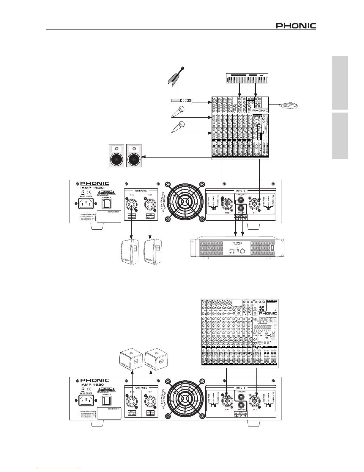
APPLICATIONS APLICACIONES
STEREO OPERATION
OPERACIÓN ESTÉREO
SUBWOOFER OPERATION
OPERACIÓN SUBWOOFER
MAIN OUT
KEYBOARD
AM442D
AM642D
LR
CD or
MP3 PLAYER
REPRODUCTOR
CD O MP3
ACTIVE MONITOR
MONITORES ACTIVOS
MICROPHONES
MICRÓFONOS
GUITAR
GUITARRA
iSK12
iAMP1620
PASSIVE SPEAKER
A
LTAVOCES PASIVOS
ADDITIONAL AMPLIFIERS
GUITAR EFFECTS
EFECTOS DE GUITARRA
SUBWOOFERS
SUBWOOFERS
䞡Ԣ䷇ㆅ
㹿ࡼᓣᡀໄ఼
CDMP3᪁ᬒ఼
TECLADO
⬉ᄤ䬂⨈
⬉ঢ়ᅗᬜᵰ఼
Џࡼᓣⲥু
呺ܟ亢
⬉ঢ়ᅗ
AMPLIFICADORES ADICIONALES
SALIDA PRINCIPAL
乱ⱘࡳ⥛ᠽᴎ
Џ㽕䕧ߎ
েໄ䘧
Ꮊໄ䘧
Page 16

2
iAMP1620 / iAMP3020
Appendix Apéndice
measurements are shown in mm/inches
DIMENSIONS DIMENSIONES
Todas las medidas están mostradas en mm/pulgadas.
482 / 19
88 / 3.5
415 / 16.4
Page 17
3
iAMP1620 / iAMP3020
Appendix Apéndice
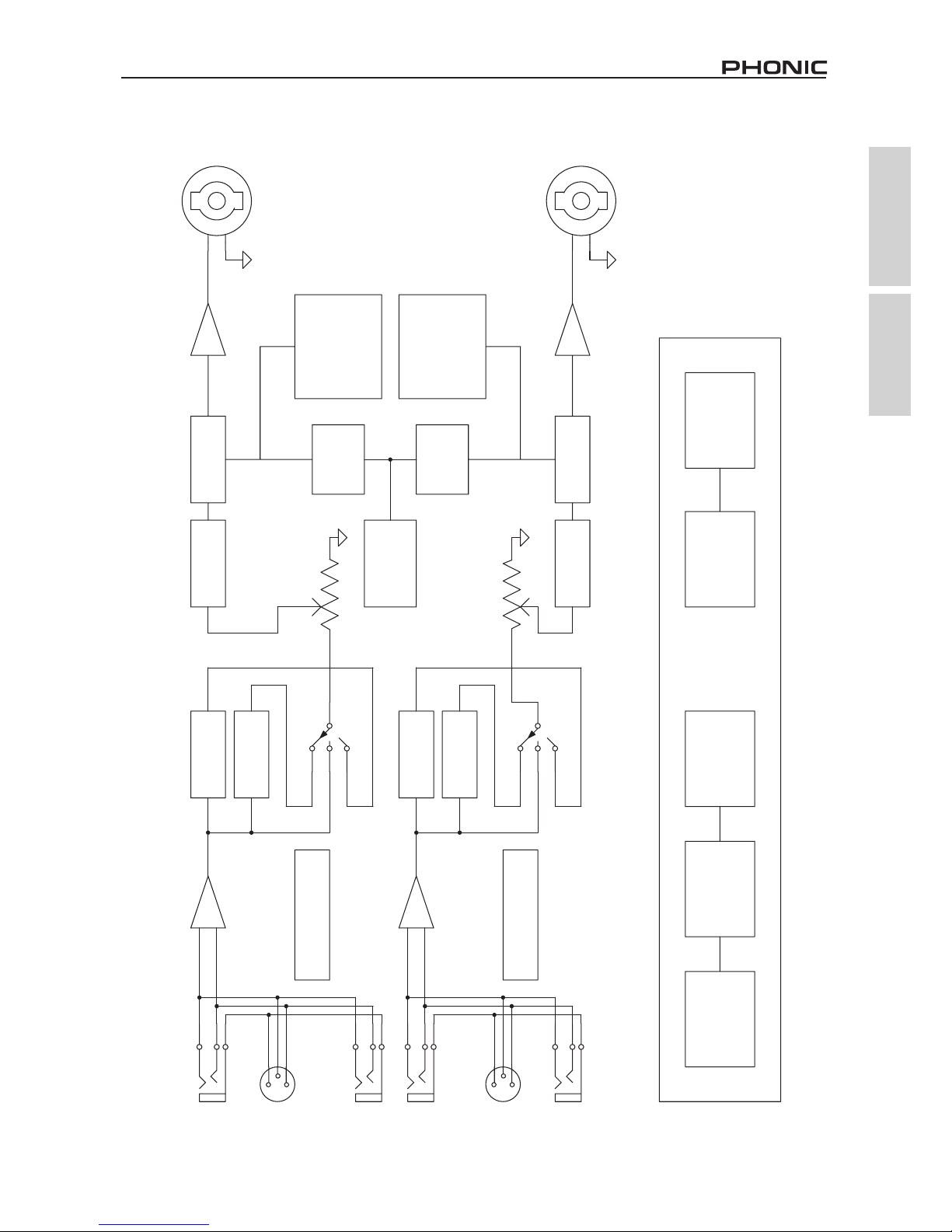
BLOCK DIAGRAM DIAGRAMA DE BLOQUE
CH1 CLASS D AMP
MUTING
R
CH2 PREAMP
MUTING
100HZ LOW
PASS FILTER
CH1 LIMITER
100HZ HIGH
PASS FILTER
T
CH2 CLASS D AMP
100HZ LOW
PASS FILTER
100HZ HIGH
PASS FILTER
CH1 PREAMP
R
CH2 LIMITER
T
OVER
CURRENT
DETECTION
EMI FILTER
SWITCHING POWER SUPPLY
INRUSH RELAY
SHUTDOWN
TRIGGERS
HALF-BRIDGE
RESONANT
CONVERTERS
OVER CURRENT
OVER VOLTAGE
UNDER VOLTAGE
DC FAULT
PROTECTION
THERMAL
SENSING
OVER CURRENT
OVER VOLTAGE
UNDER VOLTAGE
DC FAULT
PROTECTION
THERMAL
SENSING
DC FAN SPEED
ATTENUATOR
ATTENUATOR
CH2 LED INDICATOR
CH1 LED INDICATOR
FULL
FULL
SUB
HP
SUB
HP
CH1
CH2 OUT
CH1 OUT
THRU CH1
THRU CH2
1
2
3
CH2
XLR-1/4COMBO JACK
1
2
3
1
2
3
XLR-1/4COMBO JACK
1
2
3
Page 18

 Loading...