

Page 1

i7600
User's Manual
Manual del Usuario
Page 2

English Español
i7600
Digital graphic EqualizEr with rta
Eq gráfico Digital con rta
ENGLISH ..................................................I
ESPAÑOL ..................................................II
V1.1 06/07/2012
Page 3

USER'S MANUAL
CONTENTS
English
introDuction
fEaturES
hooKing it up
worKing with thE i7600
thE Eq MoDulE
thE rta MoDulE
SpEcificationS
APPENDIX
DiMEnSionS
factorY prograMS
uSEr prograMS
1
1
1
2
5
7
9
1
2
12
phonic preserves the right to improve or alter any information within this
document without prior notice
3i7600
Page 4
4 i7600
English
1. read these instructions before operating this
apparatus.
2. Keep these instructions for future reference.
3. heed all warnings to ensure safe operation.
4. follow all instructions provided in this document.
5. Do not use this apparatus near water or in locations
where condensation may occur.
6. clean only with dry cloth. Do not use aerosol or liquid
cleaners. unplug this apparatus before cleaning.
7. Do not block any of the ventilation openings. install
in accordance with the manufacturer’s instructions.
8. Do not install near any heat sources such as radiators,
heat registers, stoves, or other apparatus (including
.
9. Do not defeat the safety purpose of the polarized or
grounding-type plug. a polarized plug has two blades
with one wider than the other. a grounding type plug
has two blades and a third grounding prong. the wide
blade or the third prong is provided for your safety. if
the provided plug does not into your outlet, consult
an electrician for replacement of the obsolete outlet.
10. protect the power cord from being walked on or
pinched particularly at plug, convenience receptacles,
and the point where they exit from the apparatus.
11. only use attachments/accessories by the
manufacturer.
12. use only with a cart, stand, tripod, bracket, or
table by the manufacturer, or sold with
the apparatus. when a cart is used, use caution
when moving the cart/apparatus
combination to avoid injury from tipover.
13. unplug this apparatus during lighting
storms or when unused for long
periods of time.
14. refer all servicing to service personnel.
Servicing is required when the apparatus has been
damaged in any way, such as power-supply cord or
plug is damaged, liquid has been spilled or objects
have fallen into the apparatus, the apparatus has
been exposed to rain or moisture, does not operate
normally, or has been dropped.
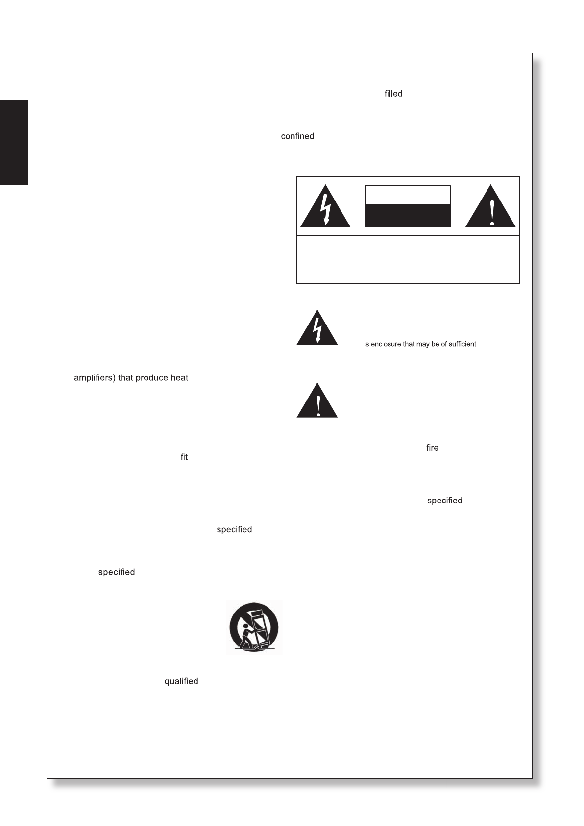
IMPOrTANT SAfETY INSTruCTIONS
caution: to rEDucE thE riSK of ElEctric ShocK,
Do not rEMoVE coVEr (or BacK)
no uSEr SErVicEaBlE partS inSiDE
rEfEr SErVicing to qualifiED pErSonnEl
the lightning flash with arrowhead symbol, within an
equilateral triangle, is intended to alert the user to the
presence of uninsulated “dangerous voltage” within the
product
’
magnitude to constitute a risk of electric shock to persons.
the exclamation point within an equilateral triangle is intended to alert the user to the presence of important operating and maintenance (servicing) instructions in the literature
accompanying the appliance.
WArNING: to reduce the risk of or electric shock, do
not expose this apparatus to rain or moisture.
CAuTION: use of controls or adjustments or performance
of procedures other than those may result in
hazardous radiation exposure.
the apparatus shall not be exposed to dripping or splashing and that no objects with liquids, such as vases,
shall be placed on the apparatus. the MainS plug is used as the disconnect device, the disconnect device shall
remain readily operable.
Warning: the user shall not place this apparatus in the area during the operation so that the mains switch
can be easily accessible.
CAuTION
rISk Of ELECTrIC SHOCk
DO NOT OPEN
Page 5

INTrODuCTION
fEATurES
thank you for choosing a phonic professional audio
product. the i7600 i SupraCurve is an innovative
product that combines a digital graphic equalizer with
a full-feature real-time spectrum analyzer (rta) in a
slender one-rack-space body. what sets the i7600
apart from the crowd is its ability to perform the rta
tasks without interrupting the Eq operations.
for a system as complex as the i7600, the controls
are surprisingly simple and intuitive. all operations
are performed on just two knobs and two buttons,
conveniently located at the center of the front
panel.
this manual is designed to be both concise and
comprehensive. it is concise enough to help you
get a quick start on using your new i
SupraCurve. it is comprehensive enough to help
you gain a full understanding of the ne product you
have purchased. we hope you will soon discover
that you have made a wise investment in buying a
phonic product.
rack mountable with a one-rack-space (1u)
chassis
total of 780 bright lED
Dual-channel, 30-band, 1/3-octave digital
graphic equalizer
Dual-channel 29-band real-time spectrum
analyzer (rta)
24-bit aD/Da converters and 32-bit digital
signal processor (DSp)
+/- 12 dB boost/cut
channel-link function
Stores up to 60 programs: 30 factory-set, 30
user-dened
Selectable unit of measurement for rta line
signal: dBu or dBV
6 viewing range options for band-level
measurement
6 response time options:
35 ms, 125 ms, 250 ms, 500 ms, 1 sec.,
and 2 sec.
peak-hold options: permanent and none
3 weighting options: a weighting, c weighting,
and at
pink noise generator outputs balanced test
signals at 0 dB
Bypass function
Variable low-pass lter (LPF) and high-
pass lter (HPF)
Balanced Xlr and 1/4" trS connectors
operating levels of +4 dBu and -10 dBV
independently selectable for input and output
user controlled key-lock function
automatic save of settings after 10 seconds of
inactivity
English
HOOkING IT uP
1. use the supplied power cord to connect the
i7600 to an ac power outlet of a suitable
voltage.
2. connect the left and right main outputs of your
mixer to the CH 1 and CH 2 ANALOG IN of
the i7600. See figure 1 for an illustration of
the rear panel.
3. connect the CH 1 and CH 2 ANALOG OuT of
the i7600 to a pair of speakers.
4. Depress or release the OPErATING LEVEL
toggle buttons so that the operating level of
ANALOG IN matches that of your mixer, and
the operating level of ANALOG OuT matches
that of your speakers.
5. turn on the POWEr switch of i7600.
1i7600
Page 6
2 i7600
English
WOrkING WITH THE i7600
Controls and Display
the i7600 consists of two modules: Eq Module and
rta Module. the Eq Module has four control modes,
and the rta Module has three. the behaviors of the
control knobs and the displayed information on the
i7600 depend largely on which module and control
mode is being used. identifying your current control
mode is the key to master the behaviors of the
controls. table 1 is designed to help you learn how
to identify the current control mode.
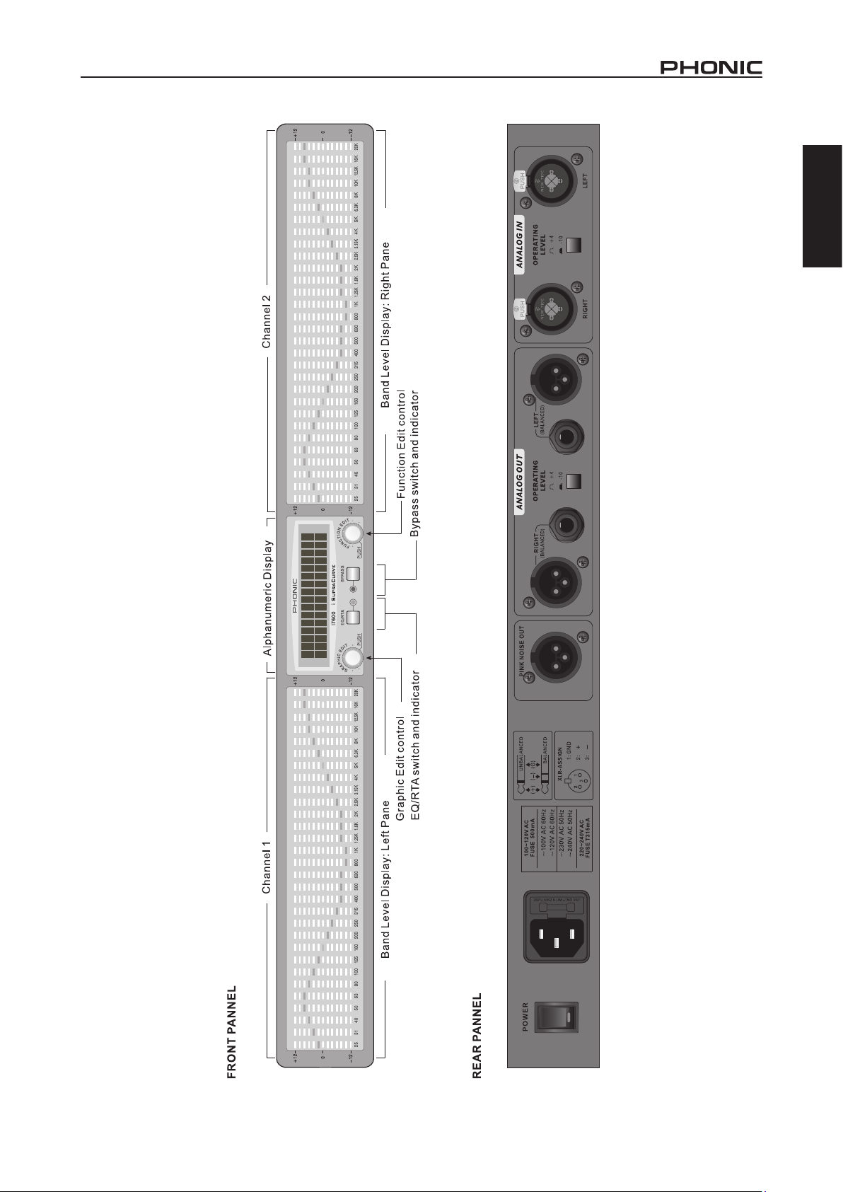
Band Level Display
the most prominent parts on the face the i7600
are the two wide panes of Band level Display. See
figure 1 for an illustration of the front panel. the left
pane is for displaying frequency and level information
of channel 1, and the right pane is for channel 2.
inside either pane are 30 columns of lEDs that
represent the 30 iSo-standard bands of the
audio spectrum in 1/3-octave intervals. Directly
below every column is a number that indicates the
center frequency of the band.
Alphanumeric Display
Between the two panes of Band level Display is
a two-line alphanumeric lcD. what information is
shown in the alphanumeric Display largely depends
on the current control mode. there is, however, a
closely followed rule: the upper line displays the
system-wide or channel-specic status, whereas
the lower line provides either the band-specic
information or the names and values of various
functions.
Clip warning
when a high-level signal exceeds the maximum
capability of the unit, the signal is automatically
compressed (clipped) in order to prevent damages
to the system circuitry. when clipping occurs in one
or both channels, a warning message is shown in
the alphanumeric Display. table 2 describes the
possible messages for clip warning.
Display Meaning
clip1 clipping at channel 1
clip2 clipping at channel 2
clip1+2 clipping at both channels
table 2: clip warning messages
if clip warnings often appear in the alphanumeric
Display, try to reduce the signal level to prevent
audio distortion. a real-time spectrum analyzer,
such as the i7600 rta Module, is the ideal tool for
identifying the frequency that is being clipped. the
i7600 can also help you nd out whether the clipped
signal is at the input (Pre EQ) stage or the output
(Post EQ) stage.
EQ Module rTA Module
Band Select
Mode
Eq/rta indicator
information type
in lcD (lower line)
flashing words
in lcD (lower line)
cursor blink rate Slow fast Slow
off off off off on on on
frequency frequency function function frequency function function
Band Edit
Mode
function
Select
Mode
Entire line Value only Entire line Value only
function Edit
Mode
Band Select
Mode
function
Select
Mode
function Edit
Mode
Table 1: Identifying modules and control modes
Page 7
English
Figure 1 : Front and rear panels
3i7600
Page 8

4 i7600
English
EQ/rTA switch and indicator
pressing the EQ/rTA button lets you switch
between the Eq Module and rta Module. the
accompanying green lED lights up when you are in
the rta Module.
GrAPHIC EDIT control
the behavior of this control knob depends on the
current control mode. generally, this knob adjusts
the band-specic settings. We will discuss this
control in greater detail later.
Bypass switch and indicator
pressing the Bypass button lets you switch the
bypass function on or off. when a channel is
bypassed, as indicated by the accompanying red
lED, none of the Eq settings are applied to the input
signal of that channel. as a result, the signal you get
from the channel output is identical to the original
input signal. this feature lets you make a quick
comparison between the original and processed
sounds. it is particularly useful when you are setting
up your system.
notE: the Channel Link status affects the
behavior of the Bypass button. when Channel
Link is on, pressing the Bypass button affects the
bypass status of both channels. when Channel
Link is off, however, which channel will be affected
by the Bypass button is determined by the location
of the cursor (that is, the blinking lED in the Band
level Display, or the left-most blinking lED in a
multiband group). if the cursor is in the left pane,
pressing the Bypass button affects only the bypass
status of channel 1. likewise, if the cursor is on the
right pane, pressing the Bypass button affects only
the bypass status of channel 2.
fuNCTION EDIT control
the behavior of this control knob also depends on
the current control mode. generally, this knob adjusts
the system-wide and channel-specic settings. We
will discuss this control in greater detail later.
Page 9

THE EQ MODuLE
functions
Controls and Display
To edit a single band
with the Eq/rta indicator off, turning or pushing the
GrAPHIC EDIT knob will bring you to the Eq Band
Select Mode. See table1 for tips on identifying the
control modes. to select a band, simply turn the
GrAPHIC EDIT knob. the selected band is the one
that has a slow-blinking lED (the cursor). to change
from channel 1 to channel 2, turn the GrAPHIC
EDIT knob clockwise until the cursor "jumps" to the
right pane. once a band is selected, you can edit
its boost/cut level by pushing the GrAPHIC EDIT
knob once. the cursor will blink faster to indicate
that you are now in the Eq Band Edit Mode. while
in this mode, turning the GrAPHIC EDIT knob will
boost or cut the gain level of the band. after you
are done editing the band level, push the GrAPHIC
EDIT knob once again to return to the Eq Band
Select Mode.
To edit a multiband group
while in the Eq Band Select Mode, turning the
fuNCTION EDIT knob lets you select multiple
bands as a group. for example, if the lED is
originally blinking only at the 10k band of channel
1, turning the fuNCTION EDIT knob clockwise
by two notches will make these three lEDs blink:
10k, 12.5k, and 16k. if instead of two notches, you
turn the knob clockwise by ve notches, you will
notice that the blinking lEDs are no longer limited
to channel 1 (at 10k, 12.5k, 16k and 20k hz), but
also include two bands of channel 2 (at 25 and 31
hz). this means you can group across the channels
even when Channel Link is off. in practice, you
may often want to raise or lower the boost/cut level
of the entire spectrum of both channels. this crosschannel grouping makes the task quick and easy
without having to link the channels.
once a group is selected, push the GrAPHIC EDIT
knob to enter the Eq Band Edit Mode; notice the
lEDs are blinking faster. now turn the GrAPHIC
EDIT knob to edit simultaneously the boost/cut level
of all selected bands. push the GrAPHIC EDIT
knob again to return to the Eq Band Select Mode.
with the EQ/rTA indicator off, pushing the fuNCTION
EDIT knob once will bring you to the Eq function
Select Mode. See table 1 for tips on identifying the
control modes. while in the Eq function Select
Mode, the upper line of the alphanumeric Display
provides important information on the current Eq
settings. This information includes the following ve
values.
program number: P1 through P30 are factory-
set programs, and u1 through u30 are user-
dened programs.
Low-pass lter: The letters LPf appears
when the low-pass lter is active. This value is
channel dependent.
High-pass lter: The letters HPf appears
when the high-pass lter is active. This value
is channel dependent.
gain: G+ indicates that a gain increase is been
applied to the output; G– is for gain decrease;
and G= is for zero gain. this value is channel
dependent.
channel link: appears when the channel link
is on. otherwise, is displayed.
the lower line of the alphanumeric Display shows
a function name and its current value. when you
are in the Eq function Select Mode, the entire
lower line is ashing. This is to remind you that, if
you turn the fuNCTION EDIT knob now, you will
be "scrolling" through the function menu. turn the
fuNCTION EDIT knob to nd the function that you
want to edit. press the fuNCTION EDIT once to
enter the Eq function Edit Mode. notice that the
function name is no longer ashing and that only
the variable value is. turning the fuNCTION EDIT
knob now will change the value for that function.
When you have nished adjusting the value, press
the fuNCTION EDIT knob again to return to the Eq
function Select Mode.
the following sections describe all functions you
can adjust in the Eq function Edit Mode.
English
5i7600
Page 10

6 i7600
English
Channel Link
when this function is set to On, all settings of channel
1 are copied to channel 2; and all subsequent
adjustments will be simultaneously applied to both
channels. when Channel Link is Off, you can
adjust each channel separately; the location of the
cursor determines which channel is to be affected.
when the cursor is in the left pane, the adjustment
is made to channel 1; and when it is in the right
pane, channel 2 is affected.
Gain
this function lets you increase or decrease the gain
level of the channel output. the range of control is
from negative innity to +6 dB. When Channel Link
is set to Off, you can adjust the gain level for each
channel separately.
Low-Pass filter (LPf)
A low-pass lter lets you "cut out" the unwanted high
frequencies. You may set the threshold frequency
anywhere between 1 khz to 20 khz in 1/6-octave
intervals. Alternatively, you may remove the lter
by setting it to Off. this function is channel
dependent.
High-Pass filter (HPf)
a high-pass lter lets you "cut out" the unwanted low
frequencies. You may set the threshold frequency
anywhere between 20 hz to 1 khz in 1/6-octave
intervals. Alternatively, you may remove the lter
by setting it to Off. this function is channel
dependent.
Store
this function lets you store your favorite settings.
You may store up to 30 programs, from u1 to u30.
information stored in a program includes all following
values for both channels: the channel-link status,
gain levels, low-pass-? lter frequencies, high-pass? lter frequencies, and boost/cut levels of all bands.
appendix B provides 30 blank diagrams for you to
record your stored programs.
key Lock
the lock function can be activated by simply
pressing the graphic and function Edit controls
simultaneously. Enabling locking means that you are
then unable to change any settings of the i7600 until
you have unlocked it once more. this helps prevents
accidental alteration of settings while the device is
in use. to turn the lock off, once again press the
graphic and function Edit controls simultaneously.
Auto Store
if the controls on the i7600 remain unused for
more than 10 seconds, your current settings will
automatically be saved and will be stored, even
after the power is turned off. this ensures that your
settings are never lost in unexpected power outages
and that you get the settings you desire most on
start up.
recall
this function lets you recall a previously stored
program. this is an easy way to set up your Eq; it is
especially useful during live events that often call for
quick changes to the Eq settings in etween songs.
You may recall any of the 60 stored programs (30
factory-set programs, from p1 to p30; and 30 userde? ned programs, from u1 to u30). See appendix
a for all factory programs. See also appendix B for
blank diagrams where you can record your favorite
settings.
caution: when you recall a program, the current
Eq settings of both channels will be lost, regardless
of the channel-link status. if you plan to use the
current setting in the future, consider storing it
before performing a recall.
Page 11

THE rTA MODuLE
Controls and Display
with the EQ/rTA indicator on, turning the
GrAPHIC EDIT knob brings you to the rta Band
Select Mode. See table 1 for tips on identifying the
control modes. continue to turn the knob to select
a band. the selection is indicated by the blinking
cursor at the bottom row of the Band level Display.
once a band is selected, the alphanumeric Display
provides the following three pieces of information:
the channel number (Channel 1 or Channel 2), the
center frequency of the band, and the real-time level
(if Peak hold is off) or the peak level (if Peak hold
is on) of the band.
notE: in the rta Module, the right-most lED
column (marked 20k) in each pane of the Band
level Display does not show the level of the 20kilohertz band; rather, it shows the over-all level of
the channel. to avoid confusion, special markings
are printed above the two 20k columns (▼―lEV)
and at the center-bottom of the front panel (▼―rta/
ch lEVEl), reminding you that these two columns
show the channel levels in the rta Module.
functions
with the EQ/rTA indicator on, turning the fuNCTION
EDIT knob brings you to the rta function Select
Mode. See table 1 for tips on identifying the control
modes. while in the rta function Select Mode, the
upper line of the alphanumeric Display provides
important information on the current rta settings.
This information includes the following ve values,
all of which are system-wide (channel-independent)
values.
The rst two values indicate the viewing
range of the Band Level Display. The rst
value represents the maximum level that can
be represented in the Band level Display. in
other words, it corresponds to the top lED in
each column. the second value, on the other
hand, represents the minimum level, and
corresponds to the bottom lED.
notE: the reference marks (+12, 0, and -12)
beside the panes of the Band level Display
are applicable only in the Eq Module. while
in the rta Module, the reference values for
the top and bottom lEDs are adjustable, and
are shown in the alphanumeric Display as
described in the previous paragraph.
weighting type: the letter A stands for a
weighting, C for c weighting, and f for at.
Signal source: the word Post indicates that
the current measurement is taken from the
processed (post-Eq) signal, whereas Pre
indicates that the measurement is taken from
the original (pre-Eq) input signal.
pink noise: the letter P appears when the
Pink noise function is set to ON.
the following sections describe all functions you
can adjust in the rta function Edit Mode.
range
this function lets you select the viewing range of
the Band level Display. two values are associated
with each selection. The rst value represents the
maximum level that can be represented in the
Band level Display. in other words, it corresponds
to the top lED in each column. the second value,
on the other hand, represents the minimum level,
and corresponds to the bottom lED. table 3 lists all
available viewing ranges.
MAX MIN
+ 30 - 6
+ 21 - 15
+ 12 - 24
+ 6 - 30
0 - 36
- 12 - 48
Table 3: Viewing ranges
Use this function to nd the appropriate viewing
range for your program. for instance, when there is
little or no action in the Band level Display, and you
are certain that signals are being fed into at least
one of the channels, you probably have set a range
that is too high. in other words, all the activities are
happening below the viewable range. try lowering
the range to resolve the problem.
English
7i7600
Page 12

8 i7600
English
on the other hand, if you see the top lEDs in most
of the bands are often lit, you probably have set a
range that is too low. try raising the range to see
whether the problem is resolved. if the problem
continues even when the highest range is selected,
try to lower the gain setting in the Eq Module (if the
measurement is post-Eq) or the output level of the
source device (if the measurement is pre-Eq).
response Time
this function determines the length of the time span
within which measurements are averaged. the
average value of each interval is represented by the
height of the lit lED in a column. in effect, the value
you choose for the response time will determine
how fast the lEDs respond to the changes in sound
intensity.
Different types of sound have different rates
of change in intensity. in order to see a faithful
representation of the sound on the lED display, you
need to adjust the response time according to the
type of sound that is being measured. choose, for
example, a short response time for a fast-attack and
fast-decay sound, such as snare-drum beats; but
opt for a longer response time for the long-sustaining
sound of a typical wind instrument.
Because of this effect, the scale of a soundlevel meter must be "weighted" in order to better
represent the loudness as perceived by an average
person. the i7600 offers two types of weighting:
the A weighting is designed to represent human
hearing for low-level sounds, at 40 phons (40 dB
Spl at 1 khz); whereas the C weighting mimics the
hearing for high-level sounds, at 100 phons (100
dB Spl at 1 khz). when you want to measure the
straightforward Spl of the signal, remember to set
the Weighting type to f (flat) for the un-weighted
scale.
unit of Measurement (dBu/dBV)
this function lets you choose the unit of measurement
for the signal level. the unit dBu is referenced to
0.775 volts rMS (0 dBu = 0.775 V), whereas the
unit dBV is referenced to 1 volt rMS (0 dBV = 1
V).
Peak Hold
when this function is set to ON, the highest level
reached in each band is indicated by an lED that
stays lit in the corresponding column in the Band
level Display. this lit lED will hold its position in
the column until it is "pushed up" by a higher-level
signal in the band.
options for the response time are: 35 ms, 125 ms,
250 ms, 500 ms, 1 second, and 2 seconds.
Weighting Type
the human ear responds differently to sounds
at different frequencies. Even when the sound
pressure level (Spl) is identical at all frequencies,
an average person tends to hear a louder midrange
sound as compared to the bass or high-frequency
sounds. however, as the Spl is increased equally
at all frequencies, the perceived loudness difference
between the midrange and bass sounds becomes
less predominant, and the difference between the
midrange and high-frequency sounds becomes
more apparent.
Signal Source (Pre EQ/Post EQ)
this function lets you choose which signal is to be
measured. Set to Pre EQ if you want to measure
the input signal in its original, unprocessed form. on
the other hand, if the processed (equalized) sound
is what you want to measure, then Post EQ is the
choice.
Pink Noise
the i7600 can generate a continuous stream of pink
noise to help you calibrate your system. turn on
this function to send out the signal stream through
the PINk NOISE OuT connector in the back of the
unit.
Page 13

SPECIfICATIONS
INPuT
connectors Balanced Xlr and 1/4” trS (combo)
nominal operating level +4 dBu or -10 dBV (determined by a rear panel switch)
impedance 20k ohms
Maximum input level +16 dBu
OuTPuT
connectors Balanced Xlr and 1/4” trS
nominal operating level +4 dBu or -10 dBV (determined by a rear panel switch)
impedance 220 ohms
Maximum output level +16 dBu
SYSTEM
frequency response 20 hz to 22 khz, +/- 0.5dB
Dynamic range 96 dB typical
thD 0.004% typical at +4 dBu, 1 khz
S/r < -90 dB
crosstalk < -80 dB, 20 hz to 22 khz
fuNTIONS
Eq Module
rta Module response time, level view range, weighting, peak hold, pink noise
DIGITAL PrOCESSING
converters 32-bit sigma-delta, 64/128-times oversampling
Sampling frequency 44.1 khz
prograM MEMorY 30 factory-set programs (read only), 30 user-dened programs (read/write)
frONT PANEL
Switches Eq/rta, Bypass
rotary controls graphic Edit, function Edit
Display Digital alphanumeric lcD
rEAr PANEL
connectors
Switches
POWEr rEQuIrEMENTS
uSa/canada ~120 V ac, 60 hz
uK/australia ~240 V ac, 50 hz
Europa ~230 V ac, 50 hz
fuse 100-120 V ac: 1 a, 200-240 V ac: 0.5 a
power consumption 15 w
power connector Standard iEc receptacle
PHYSICAL
Dimensions (wxhxD) 483 x 44 x 206 mm (19” x 1.7” x 8.1”)
weight 2.5 kg (5.5 lbs)
Dual iSo-standard 30-band, 1/3-octave, 20 hz to 20 khz, lpf, hpf,
channel gain
input x 2 (Xlr and 1/4” trS combo), output x 2 (Xlr and 1/4 trS), pink
noise (Xlr)
input operating level switch (+4 dBu/-10 dBV). output operating level
switch (+4 dBu/-10 dBV).
English
9i7600
Page 14

English
SERVICE AND REPAIR
For replacement parts, service and repairs please contact the Phonic distributor in your
country. Phonic does not release service manuals to consumers, and advice users to not
attempt any self repairs, as doing so voids all warranties. You can locate a dealer near you at
http://www.phonic.com/where/.
WARRANTY INFORMATION
Phonic stands behind every product we make with a no-hassles warranty. Warranty coverage
may be extended, depending on your region. Phonic Corporation warrants this product for a
minimum of one year from the original date of purchase against defects in material and
workmanship under use as instructed by the user’s manual. Phonic, at its option, shall repair
or replace the defective unit covered by this warranty. Please retain the dated sales receipt as
evidence of the date of purchase. You will need it for any warranty service. No returns or repairs
will be accepted without a proper RMA number (return merchandise authorization). In order to
keep this warranty in effect, the product must have been handled and used as prescribed in the
instructions accompanying this warranty. Any tampering of the product or attempts of self repair
voids all warranty. This warranty does not cover any damage due to accident, misuse, abuse,
or negligence. This warranty is valid only if the product was purchased new from an authorized
Phonic dealer/distributor. For complete warranty policy information, please visit
http://www.phonic.com/warranty/.
CUSTOMER SERVICE AND TECHNICAL SUPPORT
We encourage you to visit our online help at http://www.phonic.com/support/. There you can find
answers to frequently asked questions, tech tips, driver downloads, returns instruction and other
helpful information. We make every effort to answer your questions within one business day.
support@phonic.com
http://www.phonic.com
10 i7600
Page 15

Manual del Usuario
CONTENIDO
English Español
introDuccion
caractEriSticaS
conEctanDo toDo
traBaJanDo con El i7600
El MoDulo DE Eq
El MoDulo rta
ESpEcificacionES
APPENDIX
DiMEnSionES
prograMaS DE faBrica
prograMaS DEl uSuario
1
1
2
2
5
7
9
1
2
12
phonic se reserva el derecho de mejorar o alterar cualquier información
provista dentro de este documento sin previo aviso.
11i7600
Page 16

12 i7600
English Español
Page 17

INTrODuCCION
CArACTErISTICAS
gracias por escoger uno de los productos de audio
profesional de phonic El i7600 i Supracurve es un
producto novedoso que combina a un ecualizador
graco digital, con un analizador de espectro en
tiempo real realcen características completas (rta),
en una unidad de rack estándar. lo que separa
al i7600 del montón, es su posibilidad de realizar
trabajos rta sin interrumpir las operaciones del
Eq.
para un sistema tan complejo como el i7600, los
controles son sorprendentemente intuitivos y simples.
todas las operaciones son hechas con solo dos
perillas y dos botones, localizados convenientemente
al centro del panel frontal.
Este manual esta diseñado para ser conciso y
comprensivo. Es lo sucientemente conciso para
ayudarte a tener un rápido inicio al utilizar tu nuevo
iSupra Curve. Es lo sucientemente comprensible
para ayudarte a ganar entendimiento total del
producto tan no que has comprado. Esperamos
que pronto descubras que has hecho una inversión
inteligente al comprar uno de los productos de
phonic.
Montable en rack con chasis de 1 unidad de
rack (1ru)
780 lEDs en total
Ecualizador graco digital de canal dual, 30
bandas a 1/3-octava
analizador de espectro en tiempo real de canal
dual a 29 bandas (rta)
convertidores a/D D/a a 24-bits y procesador
digital de señal (DSp) a 32 bits
+/- 12 dB de realce/corte
función de link de canal
almacena hasta 60 programas: 30 de fabrica,
30 denidos por el usuario
unidad de medición seleccionable para el nivel
de señal de línea del rta: dBu o dBv
6 opciones de visualización de rangos para
medición de niveles de bandas
6 opciones de tiempos de respuesta:35 ms, 125
ms, 250 ms, 500 ms, 1 seg., y 2 seg.
opciones de peak-hold: permanente y
ninguna
English Español
3 opciones de ponderación (weighting) : a
weighting, C weighting y at
Salidas de generador de señales de prueba de
ruido rosa balanceadas a 0dB
función Bypass
Filtro pasa bajas variable (LPF) y ltro pasa altas
variable (hpf)
conectores Xlr y 1/4" trS balanceados
niveles de operación de +4dBu y -10dBv
seleccionables independientemente para las
entradas y salidas
función bloqueo de tecla controlada por el
usuario
Almacenado automático de conguraciones
después de 10 segundos de inactividad
1i7600
Page 18

2 i7600
English Español
CONECTANDO TODO
TrABAJANDO CON EL I7600
1. utiliza el cable de voltaje incluido para
conectar el i7600 a un tomacorriente de voltaje
adecuado
2. conecta las salidas principales izquierda y
derecha de tu mixer a los canales CH1 y CH2
de entrada ANALOGAS del i7600. Véase la
gura 1 para una ilustración del panel trasero
3. conecta los canales CH1 y CH2 de SALIDA
ANALOGA del i7600 a un par de altavoces.
4. libera o presiona los botones de NIVEL DE
OPErACIÓN, de tal manera que el nivel de
operación de la ENTrADA ANALOGA iguale la
de tu mixer, y el nivel de operación de la salida
ANALOGA iguala a la de tus altavoces.
5. Enciende al i7600
Controles y Display
El i7600 consiste de dos módulos: Modulo de
Eq y Modulo rta. El modulo de Eq tiene cuatro
modalidades de control, y el modulo rta tiene 3
modalidades. El comportamiento de las perillas
de control y la información del display en el i7600
dependen mucho del modulo y los controles que
se estén utilizando. la tabla 1 esta diseñada para
ayudarte a que aprendas como identificar los
controles de las modalidades correspondientes
Display de Nivel de banda
las partes más prominentes en la cara del i7600
son dos amplios paneles de Displays de niveles de
Bandas. Véase la gura 1 para una ilustración del
panel frontal. El panel izquierdo es para desplegar
la frecuencia y la información del nivel del canal 1,
y el panel derecho es para el canal 2. Dentro de
cualquier panel se encuentran 30 columnas de lEDs
que representan las 30 bandas iSo-estándar del
espectro del audio en intervalos de 1/3 de octava.
Directamente debajo de cada columna, un numero
indica la frecuencia central de esa banda.
Display Alfanumérico
Entre los dos paneles de Display de nivel de Banda,
se tiene un display alfanumérico lcD. la información
que sea mostrada en el Display alfanumérico
depende enormemente de la modalidad de control
correspondiente. Se tiene, de cualquier manera,
una regla a seguir: las líneas superiores muestran
el estatus del sistema en general o de un canal en
especico, mientras que las líneas inferiores proveen
ya sea información especifica de bandas o los
nombres de los valores de las distintas funciones.
Page 19

English Español
slena
p
r
a
er
dna
t
n
or
F
:
1 er
u
giF
PANEL FRONTAL
PANEL TRASERO
CANAL 1 DISPLAY ALFANUMERICO CANAL 2
DISPLAY DE NIVEL DE BANDA: PANEL IZQUIERDO
CONTROL DE EDICION GRAFICA
SELECTOR RTA EQ CON INDICADOR
CONTROL DE FUNCIONDE EDICION
DISPLAY DE NIVEL DE BANDA: PANEL DERECHO
3i7600
Page 20

4 i7600
English Español
Alarma de Clip
cuando una señal de alto nivel excede la capacidad
máxima de la unidad, la señal es automáticamente
comprimida (clipped) en orden de prevenir daños a
los circuitos del sistema. cuando se da el clip en
uno o en amos canales, se presentara un mensaje
de alarma en el Display alfanumérico. la tabla 2
describe los posibles mensajes para alarmar acerca
del clip.
Display Signicado
clip1 clipping en canal 1
clip2 clipping en canal 2
clip1+2 clipping en ambos canales
NOTA: El estatus de la función de link de canal afecta
el comportamiento del botón de Bypass. cuando el
link de canal esta activado (on), presionar el botón
de función de Bypass afectara el estatus de baypass
de ambos canales. cuando este desactivada la
función de link de canal, sin embargo, el canal
que será afectado por el botón de bypass, estará
determinado por la posición del cursor (esto es, el
lED que este intermitente en un grupo multibanda).
Si el cursor esta en el panel izquierdo, presionar el
botón de Bypass solo afectara el estatus del canal
1. De la misma manera, si el cursos esta en el panel
derecho, presionando la función de bypass afectara
solamente el estatus del canal 2.
Control de EDICION GrAfICA
Tabla 2: Mesanjes de alarma de Clip
Si aparecen continuamente avisos de clip en el
Display alfanumérico, intenta reducir el nivel de
la señal para prevenir distorsión en el audio. un
analizador de espectro en tiempo real, como el
modulo rta del i7600, es la herramienta ideal para
identicar la frecuencia que esta siento recortada. El
i7600 también puede ayudarte a encontrar si la señal
saturada esta en la etapa de entrada (pre Eq) o en
la etapa de salida (post Eq).
El comportamiento de esta perilla de control depende
de la modalidad de control actual. generalmente,
esta perilla ajusta la configuración de la banda
especica. Discutiremos este control en más detalle
más adelante.
Control de fuNCION DE EDICION
El comportamiento de esta perilla de control depende
de la modalidad de control actual. generalmente,
esta perilla ajusta toda la conguración del sistema y
la conguración del canal en especico. Discutiremos
este control en más detalle más adelante.
Selector EQ/rTA con indicador
presionando el botón Eq/rta te permitirá seleccionar
entre los módulos de Eq y rta. El lED de color
verde que lo acompaña se iluminara cuando estés
en el Modulo rta.
Selector de Bypass con Indicador
presionando el botón de bypass, te permitirá
encender o apagar esta función. cuando un canal
este en bypass, indicado por el lED rojo que lo
acompaña, nos e aplicara ninguno de los ajustes de
la ecualización a la señal de entrada de ese canal.
como resultado, la señal que obtienes en la salida
del canal es idéntica a la señal de entrada de origen.
Esta característica te permite hacer una comparación
rápida entre la señal original y el sonido procesado.
Es particularmente útil cuando estas congurando
tu sistema.
Page 21

EL MODuLO DE EQ
Controles y Display
Para editar una sola banda
con el indicador Eq/rta apagado, girar o presionar
la perilla de EDicion grafica (graphic edit) te
llevara a la Selección de Modalidad de Bandas
de EQ. Reerase a la Tabla 1 para consejos en la
identicacion de las modalidades de control. Para
seleccionar una banda, simplemente gira la perilla de
EDicion grafica. la banda seleccionada sera la
que tenga un lED que se ilumine intermitentemente
y lentamente (el cursor). para cambiarse del canal
1 al canal 2, gira la perilla de EDicion grafica
en sentido de las manecillas del reloj hasta que el
cursor ´´salte´´ al panel derecho. una vez que es
seleccionada una banda, puedes editar si nivel de
refuerzo/recorte (boos/cut) al presionar la perilla de
EDicion grafica una sola vez. El cursor estara
intermitente para indicar que estas ahora en la
Modalidad de Edición de Banda de Eq. cuando te
encuentres en esta modalidad, al girar la perilla de
EDicion grafica reforzara o recortara el nivel
de ganancia de la banda. Despues de que termines
de editar el nivel de la banda, presiona la perilla de
EDicion grafica una vez más para regresar a la
Modalidad de Seleccion de Banda de Eq.
Para editar un grupo multibanda
Mientras estes en la Modalidad de Selección de
Bandas de Eq, al girar la perilla de EDicion DE
funcion te permite seleccionar multiples bandas
como un grupo. por ejemplo, si el lED originalmente
esta intermitente solo en la banda de 10K del canal
1, girando la perilla de EDicion DE funcion en
sentido contrario del reloj dos posiciones, hara que
estos tres lEDs sean intermitentes: 10k, 12.5K y
16K. Si en lugar de dos posiciones, giras la perilla
en sentido del reloj cinco posiciones, notaras que
los lEDs intermitentes no estaran limitados al canal
1 (a 10k, 12.5k, 16k y 20khz), pero también incluye
dos bandas de Canal 2 (a 25 y 31 Hz). Esto signica
que puedes agrupar en los canales aun cuando
la función de link de canal este apagada. En la
practica, tal vez querras elevar o disminuir el nivel
de refuerzo/recorte (boost/cut) del espectro total de
ambos canales. Este agrupamiento entre canales,
hace que las tareas sean rapidas y fáciles sin tener
que utilizar el link de canal.
una vez que se selecciona un grupo, presiona la
perilla de EDicion grafica (graphic edit) para
entrar a la Modalidad de Edición de Banda de Eq;
nótese que los lEDs estarán intermitentes muy
rápidamente. ahora, gira la perilla de EDicion
grafica para editar simultáneamente el nivel de
refuerzo/recorte (boost /cut) de todas las bandas
seleccionadas. presiona la perilla de EDicion
grafica nuevamente para regresar a la Modalidad
de Selección de Bandas de Eq
funciones
con el indicador Eq/rta apagado, presionando la
perilla de funcion DE EDicion una vez, te dará
la Modalidad de Selección de función de Eq. Véase
la Tabla 1 para consejos en la identicación de las
modalidades de control. Mientras que se este en
la Modalidad de Selección de función de Eq, la
línea superior del Display alfanumérico provee de
información importante en los ajustes actuales del
Eq. Esta información incluye los siguientes cinco
valores.
programa número: p1 hasta p30 son programas
de fabrica, y u1 hasta u30 son programas
denidos por el usuario.
filtro pasa Bajas: las letras lpf aparecen
cuando los ltros pasa bajas están activos. El
valor depende del canal
filtro pasa altas: las letras hpf aparecen
cuando los ltros pasa altas están activos. El
valor depende del canal
ganancia: g+ indica que se ha aplicado un
incremento en la ganancia en la salida; ges para disminuir la ganancia; y g= es para
ganancia 0. Este valor es dependiente del
canal.
link de canal: aparece cuando el link de
canal este activado. De otra manera, es
desplegado.
la línea inferior del Display alfanumérico, muestra
el nombre de una función y su valor actual. cuando
estés en la Modalidad de Selección de función de
Eq, la línea inferior completa estará intermitente. Esto
es para recordarte, si giras la perilla de funcion
DE EDicion hacia abajo, estarás navegando en
el menú de funciones. gira la perilla de funcion
DE EDicion para encontrar la función qué quieras
editar. presiona la funcion DE EDicion una vez
para entrara a la Modalidad de Edición de función
de Eq. nota que el nombre de la función no esta
intermitente y solamente el valor variable estará así.
girando ahora la perilla de funcion DE EDicion
cambiara el valor para esa función. cuando hayas
terminado de ajustar los valores, presiona la perilla de
English Español
5i7600
Page 22

6 i7600
English Español
funcion DE EDicion nuevamente para regresar a
la Modalidad de Edición de función de Eq.
las secciones siguientes describen todas las
funciones que puedes ajustar en la Modalidad de
Edición de función de Eq.
Link de Canal
cuando esta función este activada, todos los ajustes
del canal 1 serán copiados al canal 2; y todos
los ajustes subsecuentes serán simultáneamente
aplicados en ambos canales. cuando la función de
link de canal este apagada, puedes ajustar cada
canal por separado, la posición del cursor determina
cual canal será afectado. cuando el cursor este en
el panel izquierdo, los ajustes serán hechos en el
canal 1, y cuando este en el panel derecho, el canal
2 será afectado.
Ganancia
Esta función te permite incrementar o disminuir
el nivel de ganancia del canal de salida. El rango
de control es desde negativo innito, hasta +6dB.
cuando el link de canal esta apagado, puedes ajustar
el nivel de ganancia para cada canal por separado.
lo general necesitan cambios rápidos para los ajustes
del Eq entre canciones. podrás utilizar más de 60
programas almacenados (30 de fabrica, de p1 a p30,
y 30 de usuario, de u1 hasta u30). Ve el apéndice a
para ver todos los presets de fabrica. también revisa
el apéndice B para diagramas en blanco, donde tu
puedes guardar tus conguraciones favoritas.
PrECAuCIÓN: cuando cargues un programa, la
conguración actual del EQ de ambos canales se
perderá, a pesar del estatus del link de canal. Si
tienes planeado utilizar la configuración actual,
considera guardarlos antes de cargar un nuevo
preset.
Almacenar
Esta función te permite almacenar tus conguraciones
favoritas. podrás guardar hasta 30 programas,
desde u1 hasta u30. la información contenida
en los programas incluyen todos los valores de
ambos canales, el estatus de link de canal, niveles
de ganancia, frecuencias de filtros pasa bajas,
frecuencias de filtros pasa altas y, niveles de
refuerzo/recorte (boost/cut) para todas las bandas.
El apéndice B provee de 30 diagramas de bloque
para tu archivo de programas almacenados
filtro Pasa Bajas (LPf)
un filtro pasa Bajas te permite ´´cortar´´ las
frecuencias agudas no deseadas. Puedes congurar
el umbral de frecuencia en cualquier lado entre
1khz a 20khz en intervalos de 1/6 de octava.
alternativamente, tu podrás remover el filtro al
colocarlo en la posición off. Esta función es
dependiente del canal.
filtro Pasa Altas (HPf)
un filtro pasa altas te permite ´´cortar´´ las frecuencias
agudas no deseadas. Puedes congurar el umbral
de frecuencia en cualquier lado entre 20khz a 1khz
en intervalos de 1/6 de octava. alternativamente, tu
podrás remover el ltro al colocarlo en la posición
off. Esta función es dependiente del canal.
recall
Esta función te permitirá volver a utilizar o llamar
un programa previamente almacenado. Esta es
una manera muy fácil de configurar tu Eq. Es
especialmente útil durante eventos en vivo que por
Seguridad de Teclas
Esta función puede ser activada al presionar
simplemente los controles de Edición grafica
y de función simultáneamente. permitiendo
medios de seguridad para que no puedas cambiar
ninguna conguración del i7600 hasta que tengas
desbloqueada la unidad. Esto ayuda a prevenir
alteraciones accidentales de las conguraciones
cuando el dispositivo este en uso. para quitar el
seguro, presiona nuevamente los botones de Edición
Graca y de Función simultáneamente.
Almacenado Automático
Si los controles del i7600permanecen sin uso por
más de 10 segundos, tus ajustes actuales serán
automáticamente guardados y se mantendrán, aun
después de que se apague la unidad. Esto asegurara
que tus configuraciones nunca se perderán en
apagones y que tendrás los ajustes que hiciste
cuando enciendas la unidad.
Page 23

EL MODuLO rTA
MAX MIN
+ 30 - 6
+ 21 - 15
+ 12 - 24
+ 6 - 30
0 - 36
- 12 - 48
Controles y Display
con el indicador Eq/rta activado, girando la perilla
de EDicion grafica (graphic edit) te dará la
Modalidad de Selección de Banda de rta. Véase
la tabla 1 para consejos en la identicación de los
modos de control. continua girando la perilla para
seleccionar una banda. la selección se indicara
por el cursor que estará intermitente al fondo de la
columna del Display de nivel de Banda. una vez que
se seleccione una banda, el Display alfanumérico
proveerá de la siguiente información: el numero de
canal (canal 1 o canal 2), la frecuencia central de la
banda, y el nivel en tiempo real (si la función peak
hold esta apagada), o el nivel de pico (si la función
peak hold esta encendida) de la banda.
NOTA: En el modulo rta, la columna de lEDs mas
a la derecha (marcadas como 20K) en cada panel
del Display de nivel de Bandas no muestra el nivel
de la banda de 20 khz, en su lugar, muestra el nivel
total del canal. para evitar confusiones, se imprimen
marcas especiales por encima de las dos columnas
de 20K (▼─lEV) y en el botón central del panel
frontal (▼─rta/ch lEVEl), recordándote que estas
dos columnas muestran los niveles de canal en los
módulos rta.
funciones
con el indicador Eq/rta activado, girando las
perillas de EDicion DE funcion (function edit)
tendrás la Modalidad de Selección de función rta.
Véase la tabla 1 para consejos en la identicación
de las modalidades de control. Mientras que se este
en la Modalidad de Selección de función de rta,
la línea superior del Display alfanumérico provee
de infamación importante en la conguración actual
en el rta. Esta información incluye los siguientes
cinco valores, todos estos son el sistema total
(independientes del canal).
los primeros dos valores indican el rango
de visión del Display de nivel de Bandas. El
primer valor representa el nivel máximo que
puede ser representado en el Display de nivel
de Bandas. En otras palabras, corresponde a
la parte superior de los lEDs en cada columna.
El segundo valor, por otro lado, representa el
nivel mínimo y, corresponde a la parte inferior
de los lEDs.
NOTA: las marcas de referencia (+12,0 y -12)
a un lado de los paneles del Display de nivel de
Bandas son validos únicamente en el modulo
de Eq. Mientras que en el Modulo rta, los
valores de referencia para los lEDs inferiores
y superiores son ajustables, y son para mostrar
en el Display alfanumérico como se describe
en la gráca previa.
tipo de ponderación (weigthing): la letra a
signica ponderación A, C para ponderación C
y f para flat.
Señal fuente: la palabra post, indica que la
medición actual es tomada desde la señal
procesada (post Eq), mientras que la palabra
pre, indica que la medición es tomada desde la
señal (pre Eq) de entrada de origen.
ruido rosa: la letra p aparece cuando la
función de ruido rosa esta activada (on)
las siguientes secciones describen todas las
funciones que puedes ajustar en la Modalidad de
Edición de función de rta.
rango
Esta función te permite seleccionar el rango de
visión del Display de nivel de Banda. Dos valores
son asociados con cada selección. El primer
valor representa el nivel máximo que puede ser
representado en el Display de nivel de Banda. En
otras palabras, corresponde a la parte superior de
los lEDs en cada columna. El segundo valor , por
otro lado, representa el nivel mínimo y, corresponde a
los lEDs del fondo. la tabla 3 lista todos los rangos
de visión disponibles.
Tabla 3 Rangos de visión
utiliza esta función para encontrar el rango de
visión apropiado para tu programa. cuando hay
muy poca o ninguna actividad en el Display de nivel
de Bandas, y no estas seguro de que las señales
serán alimentadas en al menos uno de los canales,
probablemente habrás congurado un rango que
es muy alto.
English Español
7i7600
Page 24

8 i7600
English Español
En otras palabras, todas las actividades estarán
pasando por debajo del rango visible. intenta reducir
el rango para resolver el problema.
por otro lado, si tu ves que la parte superior de los
lEDs en muchas de las bandas están intermitentes
continuamente, probablemente has colocado el
rango a un nivel muy mínimo. intenta elevando el
rango para ver si el problema fue resuelto. Si el
problema continua aun cuando el rango máximo
ha sido seleccionado, intenta reducir la ganancia
en el Modulo de Eq (si la medición es post-Eq) o
el nivel de salida del equipo fuente (si la medición
es pre-Eq).
entre los sonidos de frecuencias altas, y medias se
harán más aparentes.
Debido a este efecto, la escala de un medidor de
sonido, deberá ser ´´pesada´´ (weighted) esto para
representar de mejor manera la sonoridad (loudness)
como es percibida por una persona promedio. El
i7600 ofrece dos tipos de escalas (weighting): la
escala a esta diseñada para representar la audición
humana a niveles de sonidos bajos, a 40 phons
(40dB Spl a 1 khz): mientras que la escala c imita
la audición para niveles de sonido altos, a 100
phons (100 dB Spl a 1 khz). cuando quieras medir
la fortaleza de Spl de una señal, recuerda colocar
el tipo de escala de medición a f (flat) para tener
completamente sin ltros la medición.
Tiempo de respuesta
Esta función determina la duración del tiempo en
el que las mediciones serán promediadas. El valor
promedio de cada intervalo es representado por la
altura de los lEDs en una columna. En efecto, el
valor que escogiste para el tiempo de respuesta
determinara que tan rápidos los lEDs responderán
a los cambios en la intensidad del sonido.
unidad de Medición (dBu/dBV)
Esta función te permite escoger la unidad de
medición para el nivel de la señal. la unidad dB esta
referenciada a 0.775 volts rMS (0dBu= 0.0775V),
mientras que la unidad dBV esta referenciada a 1
Volt rMa (0dBV= 1V).
Peak Hold
Diferentes tipos de sonidos tienen diferentes valores
de cambios en intensidad. En orden de poder ver
una representación el del sonido en el Display
lED, necesitaras ajustar el tiempo de respuesta de
acuerdo al tipo de sonido que esta siendo medido.
Escoge, por ejemplo, un tiempo de respuesta
corto para un ataque (attack) y caída (decay) de
sonidos rápidos, como batidos de tambor; pero
opta por un tiempo de respuesta más largo para
sonidos sostenidos por largo tiempo como los de un
instrumento de viento típico.
las opciones para los tiempos de respuesta son:
35ms, 125ms, 250ms, 500 ms, 1 segundo y 2
segundos.
cuando esta función esta activada (on), el nivel
más alto alcanzado en cada banda es indicador por
el lED que permanece parpadeante en la columna
correspondiente en el Display de nivel de Banda.
Este lED parpadeante, detendrá su posición en la
columna hasta que sea ´´empujado´´ por una señal
de mayor nivel de señal.
Señal fuente (Pre EQ/Post EQ)
Esta función te permite escoger cual señal será
medida. Selecciona pre Eq si quieres medir la señal
de entrada en su origen, sin procesar. por otro lado,
si el sonido procesado (ecualizado) es lo que quieres
medir, entonces selecciona post Eq para hacerlo.
Tipo de Escalas (Weighting)
El oído humano responde diferente a diferentes
sonidos a diferentes frecuencias. aun cuando el nivel
de presión sonora (Spl) sea idéntico en todas las
frecuencias, una persona promedio tiende a escuchar
los sonidos de frecuencias medias más fuertes,
comparadas con los sonidos graves o de frecuencias
agudas. Sin embargo, mientras que el Spl se
incremente de igual manera en todas las frecuencias,
la sonoridad (loudness) percibida diferenciara entre
los sonidos de frecuencias de rango medio y graves
ruido rosa
El i7600 pude generar un ujo constante de ruido
rosa para ayudarte a calibrar tu sistema. Enciende
esta función para enviar la señal de audio de salida
a través del conector de salida de ruido rosa (pink
noise out) en la parte trasera de la unidad.
Page 25

ESPECIfICACIONES
ENTrADA
conectores Xlr balanceadas y 1/4” trS (combo)
nivel de operación nominal +4 dBu o -10 dBV (determinado por el selector del panel trasero)
impedancia 20k ohms
nivel de Entrada Máximo +16 dBu
SALIDA
conectores Xlr balanceadas y 1/4” trS
nivel de operación nominal +4 dBu o -10 dBV (determinado por el selector del panel trasero)
impedancia 220 ohms
nivel de Salida Máximo +16 dBu
SISTEMA
respuesta en frecuencia 20 hz a 22 khz, +/- 0.5dB
rango dinámico 96 dB típicos
thD 0.004% típicos a +4 dBu, 1 khz
S/r < -90 dB
crosstalk < -80 dB, 20 hz a 22 khz
fuNCIONES
Módulo de Eq
Módulo de rta
PrOCESAMIENTO DIGITAL
convertidores 32-bit sigma-delta, 64/128-tiempos de sobre muestreo
frecuencia de Musetreo 44.1 khz
MEMoria DE prograMaS 30 presets de fabrica (solo lectura), 30 presets de usuario (lectura/escritura).
PANEL frONTAL
Selectores Eq/rta, Bypass
controles giratorios Edición Gráco, Edición de Función
Display lcD Digital alfanumérico
PANEL TrASErO
conectores
Selecotres
rEQuErIMIENTOS DE POTENCIA
uSa/canadá ~120 V ac, 60 hz
uK/australia ~240 V ac, 50 hz
Europa ~230 V ac, 50 hz
fusible 100-120 V ac: 1 a, 200-240 V ac: 0.5 a
consumo de potencia 15 w
conector de Voltaje receptaculo iEc estándar
fISICO
Dimensiones (anxalxl) 483 x 44 x 206 mm (19” x 1.7” x 8.1”)
peso 2.5 kg (5.5 lbs)
30 bandas duales estándar iSo, 1/3-octava, 20 hz a 20 khz,
lpf, hpf, ganancia de canal
tiempo de respuesta, rango de visión de nivel, escala (weighting),
peak hold, ruido rosa
Entradas x 2 (Xlr y 1/4” trS combo),
Salida x 2 (Xlr y 1/4 trS) ruido rosa (Xlr).
Selector de nivel de operación de entrada (+4 dBu/-10 dBV),
selector de nivel de operación (+4 dBu/-10 dBV).
English Español
9i7600
Page 26

English Español
SERVICIO Y REPARACIÓN
Para refacciones de reemplazo y reparaciones, por favor póngase en contacto con nuestro
distribuidor de Phonic en su país. Phonic no distribuye manuales de servicio directamente a los
consumidores y, avisa a los usuarios que no intenten hacer cualquier reparación por si mismo,
haciendo ésto invalidará todas las garantías del equipo. Puede encontrar un distribuidor cerca
de usted en http://www.phonic.com/where/.
INFORMACIÓN DE LA GARANTIA
Phonic respalda cada producto que hacemos con una garantía sin enredo. La cobertura de
garantía podría ser ampliada dependiendo de su región. Phonic Corporation garantiza este
producto por un mínimo de un año desde la fecha original de su compra, contra defectos en
materiales y mano de obra bajo el uso que se instruya en el manual del usuario. Phonic, a su
propia opinión, reparará o cambiará la unidad defectuosa que se encuentra dentro de esta
garantía. Por favor, guarde los recibos de venta con la fecha de compra como evidencia de la
fecha de compra. Va a necesitar este comprobante para cualquier servicio de garantía. No se
aceptarán reparaciones o devoluciones sin un número RMA apropiado (return merchandise
autorization). En orden de tener esta garantía válida, el producto deberá de haber sido
manejado y utilizado como se describe en las instrucciones que acompañan esta garantía.
Cualquier atentado hacia el producto o cualquier intento de repararlo por usted mismo,
cancelará completamente esta garantía. Esta garantía no cubre daños ocasionados por
accidentes, mal uso, abuso o negligencia. Esta garantía es válida solamente si el producto fue
comprado nuevo de un representante/distribuidor autorizado de Phonic. Para la información
completa acerca de la política de garantía, por favor visite http://www.phonic.com/warranty/.
SERVICIO AL CLIENTE Y SOPORTE TÉCNICO
Le invitamos a que visite nuestro sistema de ayuda en línea en www.phonic.com/support/. Ahí
podrá encontrar respuestas a las preguntas más frecuentes, consejos técnicos, descarga de
drivers, instrucciones de devolución de equipos y más información de mucho interés. Nosotros
haremos todo el esfuerzo para contestar sus preguntas lo antes posible.
support@phonic.com
http://www.phonic.com
10 i7600
Page 27

DIMENSIONS DIMENSIONES
Appendix Apéndice
measurements are shown in mm/inches
todas las medidas están mostradas en mm/pulgadas.
1i7600
Page 28

2 i7600
Appendix Apéndice
fACTOrY PrOGrAMS PrOGrAMAS DE fABrICA
Page 29

Appendix Apéndice
3i7600
Page 30

4 i7600
Appendix Apéndice
Page 31

Appendix Apéndice
5i7600
Page 32

6 i7600
Appendix Apéndice
Page 33

Appendix Apéndice
7i7600
Page 34

8 i7600
Appendix Apéndice
Page 35

Appendix Apéndice
9i7600
Page 36

10 i7600
Appendix Apéndice
Page 37

Appendix Apéndice
11i7600
Page 38

12 i7600
Appendix Apéndice
uSEr PrOGrAMS PrOGrAMAS DEL uSuArIO
1u
2u
3u
Page 39

Appendix Apéndice
4u
5u
6
u
13i7600
Page 40

14 i7600
Appendix Apéndice
7
u
8u
9
u
Page 41

Appendix Apéndice
0
1u
1
1u
21u
15i7600
Page 42

16 i7600
Appendix Apéndice
31
u
41u
5
1
u
Page 43

Appendix Apéndice
6
1u
7
1u
81u
17i7600
Page 44

18 i7600
Appendix Apéndice
91
u
02u
1
2
u
Page 45

Appendix Apéndice
2
2u
3
2u
42u
19i7600
Page 46

20 i7600
Appendix Apéndice
52
u
62u
7
2
u
Page 47

Appendix Apéndice
8
2u
9
2u
03u
21i7600
Page 48

 Loading...