

i7350
User's Manual
Manual del Usuario

ENGLISH ..................................................I
ESPAÑOL ..................................................II
V1.1 06/07/2012
DIGITAL EFFECTS PROCESSOR
PROCESADOR DIGITAL DE EFECTOS
i7350
English Español

3i7350
English
INTRODUCTION
1
FEATURES
1
GETTING STARTED
1
FRONT-PANEL DESCRIPTION
2
REAR-PANEL DESCRIPTION
2
SAMPLE CONNECTIONS
3
SPECIFICATIONS
4
APPENDIX
DIGITAL EFFECTS TABLE
1
CONTENTS
USER'S MANUAL
Phonic preserves the right to improve or alter any information within this
document without prior notice

4 i7350
English
1. Read these instructions before operating this
apparatus.
2. Keep these instructions for future reference.
3. Heed all warnings to ensure safe operation.
4. Follow all instructions provided in this document.
5. Do not use this apparatus near water or in locations
where condensation may occur.
6. Clean only with dry cloth. Do not use aerosol or liquid
cleaners. Unplug this apparatus before cleaning.
7. Do not block any of the ventilation openings. Install
in accordance with the manufacturer’s instructions.
8. Do not install near any heat sources such as radiators,
heat registers, stoves, or other apparatus (including
.
9. Do not defeat the safety purpose of the polarized or
grounding-type plug. A polarized plug has two blades
with one wider than the other. A grounding type plug
has two blades and a third grounding prong. The wide
blade or the third prong is provided for your safety. If
the provided plug does not into your outlet, consult
an electrician for replacement of the obsolete outlet.
10. Protect the power cord from being walked on or
pinched particularly at plug, convenience receptacles,
and the point where they exit from the apparatus.
11. Only use attachments/accessories by the
manufacturer.
12. Use only with a cart, stand, tripod, bracket, or
table by the manufacturer, or sold with
the apparatus. When a cart is used, use caution
when moving the cart/apparatus
combination to avoid injury from tipover.
13. Unplug this apparatus during lighting
storms or when unused for long
periods of time.
14. Refer all servicing to service personnel.
Servicing is required when the apparatus has been
damaged in any way, such as power-supply cord or
plug is damaged, liquid has been spilled or objects
have fallen into the apparatus, the apparatus has
been exposed to rain or moisture, does not operate
normally, or has been dropped.
IMPORTANT SAFETY INSTRUCTIONS
CAUTION: TO REDUCE THE RISK OF ELECTRIC SHOCK,
DO NOT REMOVE COVER (OR BACK)
NO USER SERVICEABLE PARTS INSIDE
REFER SERVICING TO QUALIFIED PERSONNEL
The lightning flash with arrowhead symbol, within an
equilateral triangle, is intended to alert the user to the
presence of uninsulated “dangerous voltage” within the
product
’
magnitude to constitute a risk of electric shock to persons.
The exclamation point within an equilateral triangle is intended to alert the user to the presence of important operating and maintenance (servicing) instructions in the literature
accompanying the appliance.
WARNING: To reduce the risk of or electric shock, do
not expose this apparatus to rain or moisture.
CAUTION: Use of controls or adjustments or performance
of procedures other than those may result in
hazardous radiation exposure.
The apparatus shall not be exposed to dripping or splashing and that no objects with liquids, such as vases,
shall be placed on the apparatus. The MAINS plug is used as the disconnect device, the disconnect device shall
remain readily operable.
Warning: the user shall not place this apparatus in the area during the operation so that the mains switch
can be easily accessible.
CAUTION
RISK OF ELECTRIC SHOCK
DO NOT OPEN

1i7350
English
INTRODUCTION
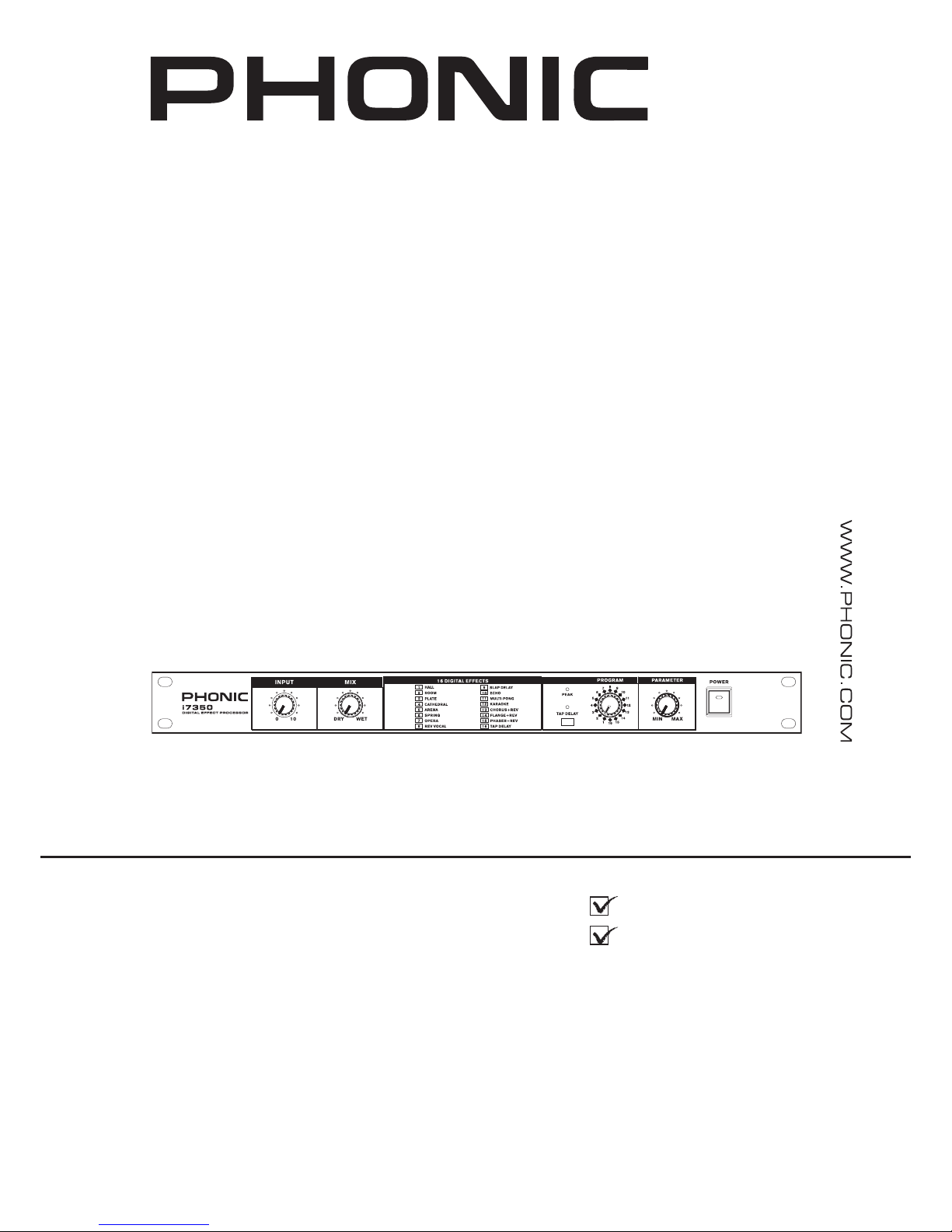
Congratulations on your purchase of the Phonic i7350 digital
reverberator. The i7350 is a high quality and easy-to-use stereo
digital reverberator. To take full advantage of the i7350’s functions,
and enjoy a long and trouble-free use, please read this user’s
manual carefully and keep it for future reference.
FEATURES
● 16 digital effects
● Programs include hall, room, spring, rev vocal, slap delay and
multiple reverb variations
● 32/40-bit digital signal processing plus 24-bit A/D and D/A
converters
● Dedicated parameter control for adjusting each effect’s main
parameter
● Auto-bypass when power is off
● Tap delay button and indicator
GETTING STARTED
1. Check the AC voltage before connecting the plug. Choose
the main supply for the sound system with care. Do not share
sockets or earthing with light dimmers.
2. Run audio cables separately from dimmer wiring, using
balanced lines wherever possible. If necessary, cross audio
and lighting cables at 90 degree right angles to minimize the
possibility of interference. Keep unbalanced cabling as short
as possible.
3. Check your cables regularly and label each end for easy
identication.
4. Before switching on the main power, keep all output rotary
faders all the way down to prevent damage or excessive
noise caused by bad level adjustment, wrong wiring, defective
cables, or bad connections.
5. Always turn on the i7350 before the power amplier; turn off
the i7350 after turning off the amplier.
6. Always turn off the unit before connecting or disconnecting
the unit to the power source.
7. Never use any solvents to clean the unit. Clean it with a soft,
dry cloth.
2 i7350
English
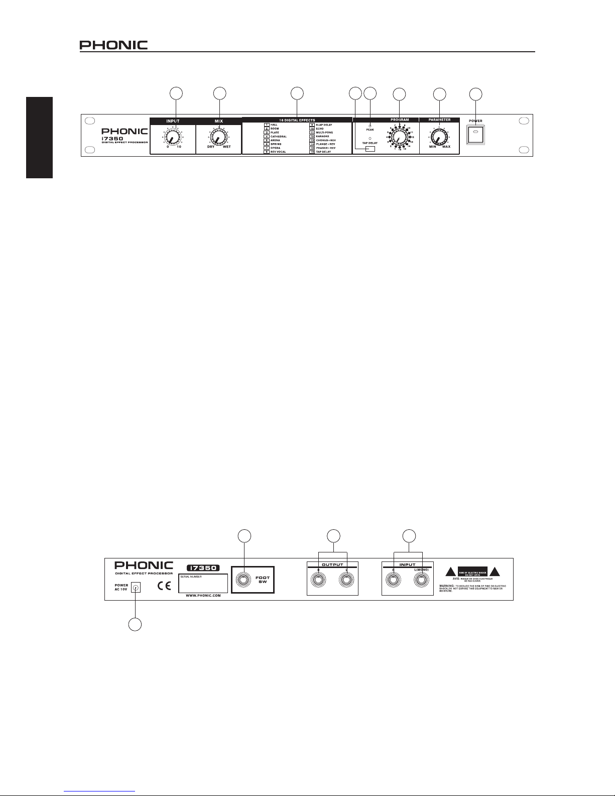
FRONT-PANEL DESCRIPTION
1. INPUT LEVEL CONTROL
The input level control sets the level going into the i7350. You
should set the level so that Peak indicators only ash RED
occasionally.
2. MIX (DRY / WET) CONTROL
This control sets the balance between the unaffected signal coming
through the inputs and the effects being generated by the I7350
i.e. the balance of wet (effect) and dry (no effect) sounds. By
keeping the Mix somewhere in the center, a blend of dry and wet
signal can be achieved.
3. EFFECT NAMES
Each effect and its corresponding effect number is listed here.
4. TAP DELAY BUTTON AND LED
When the tap delay button is selected, this control will adjust the
delay time used for the effect. Pushing it twice is succession will
measure the time between the two pushes and use this as the
delay time. In the case the button is pushed multiple times, the time
between the last two taps will be used. The LED that accompanies
this control will ash at the selected intervals.
5. PEAK LED
This LED will light up when the input signal of the i7350 hits high
peaks, just prior to overload occuring. If this LED lights up too
frequently and there are noticeable problems with the audio, it is
suggested that the input level control be reduced.
6. PROGRAM SELECT KNOB
Turning this control will allow users to select a new digital effect.
Each number on this control corresponds with a single effect, which
are listed in the effect names section. For further details on effects
and their parameters, please check the digital effect table.
7. PARAMETER CONTROL
This rotary control adjusts the level of the selected effect’s
parameter. Each effect has its own designated parameter. Users
are advised to check the digital effect table for details.
8. POWER SWITCH
This switch turns the power of the i7350 on/off. When the power
is off, the i7350 will be in signal bypass position automatically i.e.
this feature allows the direct signal to pass through the I7350 even
when the power is not switched on.
REAR-PANEL DESCRIPTION
9. AC 10V IN INLET
The supplied AC Adapter is plugged into this connector.
10. FOOTSWITCH
This is a 1/4” stereo phone jack. If a foot switch is connected to
this jack, you can use your foot to switch the effect mute on/off
(bypass).
11. OUTPUT (LEFT & RIGHT)
There are 1/4” phone jacks which connect to devices such as the
effects returns on a mixing console or power amplier inputs.
12. INPUT (LEFT/MONO & RIGHT)
There are 1/4” phone jacks which connect to sources such as the
effects sends of mixing consoles. For mono application, use the
“Left/Mono” input.
1 2 3 5
6 7 8
4
10
1
9
11 12
 Loading...