

Page 1
AM55/AM85
AM105/AM105FX
AM125/AM125FX
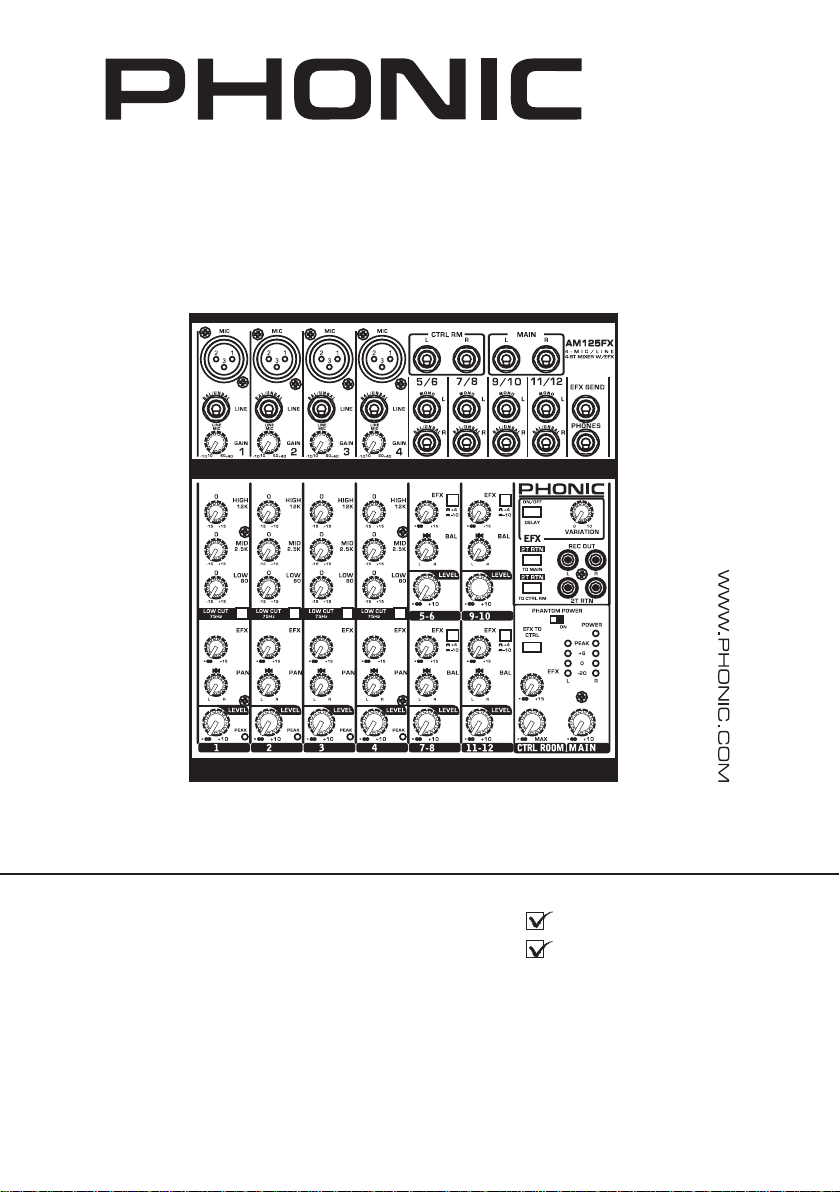
AM125FX
User's Manual
Manual del Usuario
Page 2

English Español
AM55/AM85
AM105/AM105FX
AM125/AM125FX
COMPACT MIXERS
MIXERS COMPACTAS
ENGLISH .....................................I
ESPAÑOL .....................................II
V1.1 05/25/2012
Page 3

USER'S MANUAL
CONTENTS
English
INTRODUCTION
FEATURES
INSTANT SETUP
MAKING CONNECTIONS
CONTROLS AND SETTINGS
SPECIFCATIONS
APPENDIX
APPLICATION
DIMENSIONS
Phonic preserves the right to improve or alter any information within this
document without prior notice
1
1
2
3
4
6
1
5
AM55/AM85/AM105/AM105FX/AM125/AM125FX
3
Page 4
1. Read these instructions before operating this
apparatus.
2. Keep these instructions for future reference.
3. Heed all warnings to ensure safe operation.
4. Follow all instructions provided in this document.
5. Do not use this apparatus near water or in locations
where condensation may occur.
6. Clean only with dry cloth. Do not use aerosol or liquid
cleaners. Unplug this apparatus before cleaning.
7. Do not block any of the ventilation openings. Install
in accordance with the manufacturer’s instructions.
8. Do not install near any heat sources such as radiators,
heat registers, stoves, or other apparatus (including
.
9. Do not defeat the safety purpose of the polarized or
grounding-type plug. A polarized plug has two blades
with one wider than the other. A grounding type plug
has two blades and a third grounding prong. The wide
blade or the third prong is provided for your safety. If
the provided plug does not into your outlet, consult
an electrician for replacement of the obsolete outlet.
10. Protect the power cord from being walked on or
pinched particularly at plug, convenience receptacles,
and the point where they exit from the apparatus.
11. Only use attachments/accessories by the
manufacturer.
12. Use only with a cart, stand, tripod, bracket, or
table by the manufacturer, or sold with
the apparatus. When a cart is used, use caution
when moving the cart/apparatus
combination to avoid injury from tipover.
13. Unplug this apparatus during lighting
storms or when unused for long
periods of time.
14. Refer all servicing to service personnel.
Servicing is required when the apparatus has been
damaged in any way, such as power-supply cord or
plug is damaged, liquid has been spilled or objects
have fallen into the apparatus, the apparatus has
been exposed to rain or moisture, does not operate
normally, or has been dropped.
IMPORTANT SAFETY INSTRUCTIONS
CAUTION: TO REDUCE THE RISK OF ELECTRIC SHOCK,
DO NOT REMOVE COVER (OR BACK)
NO USER SERVICEABLE PARTS INSIDE
REFER SERVICING TO QUALIFIED PERSONNEL
The lightning flash with arrowhead symbol, within an
equilateral triangle, is intended to alert the user to the
presence of uninsulated “dangerous voltage” within the
product
’
magnitude to constitute a risk of electric shock to persons.
The exclamation point within an equilateral triangle is intended to alert the user to the presence of important operating and maintenance (servicing) instructions in the literature
accompanying the appliance.
WARNING: To reduce the risk of or electric shock, do
not expose this apparatus to rain or moisture.
CAUTION: Use of controls or adjustments or performance
of procedures other than those may result in
hazardous radiation exposure.
The apparatus shall not be exposed to dripping or splashing and that no objects with liquids, such as vases,
shall be placed on the apparatus. The MAINS plug is used as the disconnect device, the disconnect device shall
remain readily operable.
Warning: the user shall not place this apparatus in the area during the operation so that the mains switch
can be easily accessible.
CAUTION
RISK OF ELECTRIC SHOCK
DO NOT OPEN
English
4
AM55/AM85/AM105/AM105FX/AM125/AM125FX
Page 5

INTRODUCTION
Congratulations on purchasing one of Phonic’s
many quality compact mixers. The entire AM series
of mixers – designed by the ingenious engineers
that have created a variety of mixers fantastic in
style and performance in the past – displays simi-
lar prociency that previous Phonic products have
shown; with more than a few renements, of course.
The AM series features full gain ranges, amazingly
low distortion levels, +22 dBu line signal handling,
and incredibly wide dynamic ranges, just showing
the dominance these small machines will have in
the studio or live venues.
We know how eager you are to get started – wanting to get the mixer out and hook it all up is probably
your number one priority right now – but before you
do, we strongly urge you to take a look through this
manual. Inside, you will find important facts and
gures on the set up, use and applications of your
brand new mixer. If you do happen to be one of the
many people who atly refuse to read user manu als, then we just urge you to at least glance at the
Instant Setup section. After glancing at or reading
through the manual (we applaud you if you do read
the entire manual), please store it in a place that is
easy for you to find, because chances are there’s
something you missed the rst time around.
FEATURES
AM55
Audiophile-quality mic preamps & ultra low noise
1 mic/line and 2 stereo channels
2-Band EQ on mono input channel
2T RTN & 2T REC for CD or tape recorder
Dual 4-segment master level meter
Headphones output with volume control
Peak LED on mono input channel
Balanced master output
AM85
Audiophile-quality & ultra low noise
Two balanced Mic/Line inputs with 3-band EQ
Two stereo inputs with 3-band EQ
One stereo aux return
Post-fader EFX send on every input
Global +48V phantom power
Peak and VU Metering
Peak indicators on each mono input channel
2T RTN assignable individually to Main or Control
room
Balanced master output
AM105
Audiophile-quality & ultra low noise
Two balanced Mic/Line inputs with 3-band EQ and
low cut
Four stereo inputs with +4/-10 select button
Post-fader AUX send on every input
Global +48V Phantom Power
CTRL RM and headphones outputs
Peak indicators on each mono input channel
Convenient RCA stereo I/O
AM105FX
Audiophile-quality & ultra low noise circuitry
Two balanced Mic/Line inputs with 3-band EQ and
low cut
Four stereo inputs with +4/-10 select button
Post-fader AUX send on every input
Global +48V Phantom Power
CTRL RM and headphones outputs
Peak indicators on each mono input channel
Convenient RCA stereo I/O
Variable delay effect with variation control
Balanced master output
AM125
Audiophile-Quality & ultra low noise
4 mono mic/line channels
4 stereo channels
AUX sends on each channel
75Hz low-cut lter on mono channel
3-band EQ on each mono channel
+48V phantom power on mic channels
Control room/Phones source matrix for maximum
monitor exibility
AUX send cue for monitoring individual channel
AM125FX
Audiophile-Quality & ultra low noise
4 mono mic/line channels
4 stereo channels
AUX sends on each channel
75Hz low-cut lter on mono channel
3-band EQ on each mono channel
+48V phantom power on mic channels
Control room/Phones source matrix for maximum
monitor exibility
AUX send cue for monitoring individual channel
Variable delay effect with variation control
Balanced TRS output
English
AM55/AM85/AM105/AM105FX/AM125/AM125FX
1
Page 6

INSTANT SETUP
Getting Started
1. Ensure all power is turned off on your mixer. To
English
totally ensure this, the AC cable should not be
connected to the unit.
2. All faders and level controls should be set at the
lowest level and all channels switched off to ensure no sound is inadvertently sent through the
outputs when the device is switched on. All levels
can be altered to acceptable degrees after the
device is turned on.
3. Plug all necessary instruments and equipment
into the device’s various inputs as required.
This may include line signal devices, such as
keyboards and drum machines, as well as microphones and/or guitars, keyboards, etc.
4. Plug any necessary equipment into the device’s
various outputs. This could include ampliers and
speakers, monitors, signal processors, and/or
recording devices.
5. Plug the supplied AC power supply into the inlet
on the rear of the device and then into a power
outlet of a suitable voltage.
6. Turn the power switch on and follow the channel setup instructions to get the most out of your
equipment.
Channel Setup
1. To ensure the correct audio level of the input
channel is selected, each of the level input controls of the Mixer should be turned counterclockwise as far as they will turn (which should be the
-∞ mark).
2. No input other than the one being set should
have any device plugged in. This will ensure the
purest signal is used when setting channels.
3. Ensure the channel has a signal sent to it similar
to the signal that will be sent when in common
use. For example, if the channel is using a microphone, then you should speak or sing at the
same level the performer normally would during a
performance; if a guitar is plugged into the channel, then the guitar should also be strummed as
it normally would be (and so on). This ensures
levels are completely accurate and avoids having
to reset them later.
4. Set the gain so the level meter indicates the audio level is around 0 dB.
5. This channel is now ready to be used; you can
stop making the audio signal.
6. You can repeat the same process for other channels.
2
AM55/AM85/AM105/AM105FX/AM125/AM125FX
Page 7
MAKING CONNECTIONS
Inputs and Outputs
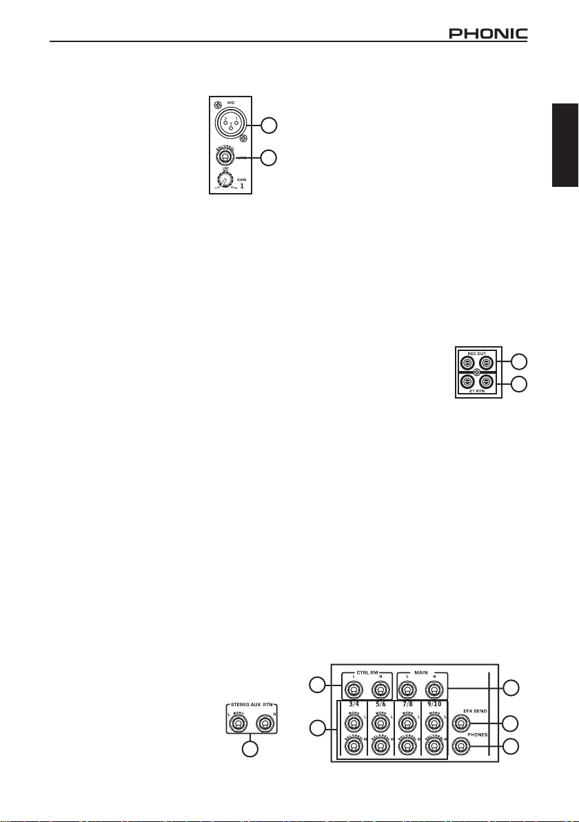
1. XLR Microphone Jacks
These ja cks accept typical
3-pin XLR inputs for balanced
and unbalanced signals. They
can be used in conjunction
with microphones – such as
professional condenser, dynamic
or ribbon microphones – with
standard XLR male connectors,
and feature low noise preamplifiers, serving for
crystal clear sound replication. With exception to
the AM55, each of the AM series mixers features
two standard XLR microphone inputs for your
convenience.
NB. When these inputs are u sed with c o n denser
microphones, the Phantom Power should be activated.
However, when Phantom Power button is engaged, single
ended (unbalanced) microphones and instruments should not
be used on the Mic inputs unless specically approved by the
microphone manufacturer.
2. Line Inputs
This input accepts typical 1/4” TRS or TS inputs for
balanced or unbalanced signals. There are various
numbers of these inputs depending which mixer
you are using. They can be used in conjunction with
various line level devices, such as keyboards, drum
machines, electric guitars, and a variety of other
electric instruments.
3. Stereo Channels
Each of the AM Mixers feature a few stereo channels,
thrown in for maximum flexibility. Each of these
stereo channels features two 1/4” phone jacks, for
the addition of various line level input devices, such
as electronic keyboards, guitars and external signal
processors or mixers. These stereo channels can
also be used as mono channels, where the signal
from any 1/4” phone jack plugged into the left stereo
input will cause the signal to duplicate to the right
input also. This does not work in reverse, however.
4. Main L and R Output
These two ports will output the nal stereo line level
signal sent from the main mixing bus. The primary
purpose of these jacks is to send the main output to
external devices, which may include power ampliers
(and in-turn, a pair of speakers), other mixers, as well
as a wide range of other possible signal processors
(equalizers, crossovers, etcetera).
5. Stereo AUX Return (AM85 only)
These 1/4” TS inputs are for the
return of audio to the AM85 mixer,
processed by an external signal
processor. If really needed, they can
also be used as additional inputs, with
a level control located on the face of
AM55/AM85/AM105/AM105FX/AM125/AM125FX
1
2
AM85
5
the mixer. The Stereo AUX Return can also accept
mono signals. Like with the stereo input channels,
these inputs can be used as mono channels by
plugging the 1/4” phone plug of any mono device into
the Stereo AUX return’s left input.
6. AUX/EFX Send (AM85, AM105, AM105FX,
AM125 and AM125FX only)
These 1/4” TS outputs may be used to connect to
an external digital effect processor, or even to an
amplier and speakers (depending on your desired
settings) to the mixer. The signal is taken from the
AUX control on each input channel. On the AM105FX
and AM125FX, the signal sent from this output is
taken from the built-in effect engine. This output
is only featured on the AM85, AM105, AM105FX,
AM125 and AM125FX mixers; therefore you shouldn’
t go looking for it on the AM55.
7. Phones
This stereo output port is suited for use with
headphones, allowing monitoring of the mix. The
audio level of this output is controlled using the
Phones or Phones/Control Room control.
8. 2T Record / Record Out
These outputs will accommodate
RCA cables, able to be fed to a
variety of recording devices.
9. 2T Return
These RCA inputs are used to connect the mixer
with parallel external devices, such as sub mixers or
external effect processors, receiving the processed
signal from another source and feeding it to either
the Main L and R or the Phones mixing bus.
10. Control Room Outputs (AM85, AM105,
AM105FX, AM125 and AM125FX only)
These two 1/4” phone jack outputs feed the signal
altered by the Control Room/Phones level control
on the face of the mixer. This output has extensive
use, as it can be used to feed the signal from the
mixer to an active monitor, for the monitoring of the
audio signal from within a booth, or, alternatively, for
the addition of external signal processing devices
or mixers, as well as acting as a “side fill” output,
supplying audio to indoor areas that the main
speakers do not reach. This output is featured on
the AM85, AM105, AM105FX, AM125 and AM125FX
mixers only.
10
3
8
9
4
6
7
3
English
Page 8
Rear Panel
11. Power Connector
This port is for the addition of the
English
external power supply, allowing power to
be supplied to the mixer. Please use the
power supply unit that is included with
the mixer only.
CONTROLS AND SETTINGS
Channel Controls
12. Line/Mic Gain Control
This controls the sensitivity of the
inputsignal of the Line/Microphone
input. Th e gain sh ou ld b e
adjusted to a level that allows the
maximum use of the audio, while
still maintaining the quality of the
feed. This can be accomplished
by adjusting it to a level that
will allow the peak indicator
occasionally illuminate. The AM55 features a single
gain control for channel 1, located on the face of the
mixer, whereas the AM85, AM105 and AM105FX
all feature gain controls on both channels 1 and 2,
located directly below the Line inputs. The AM125
and AM125FX feature gain controls on channels 1
through 4.
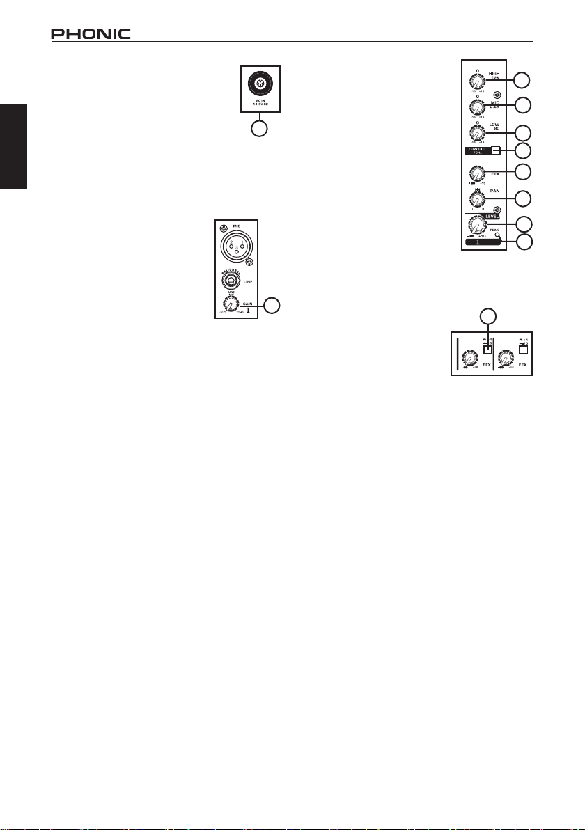
13. High Frequency Control
This control is used to give a shelving boost or cut
of ±15 dB to high frequency (12 kHz) sounds. This
will adjust the amount of treble included in the audio
of the channel, adding strength and crispness to
sounds such as guitars, cymbals, and synthesizers.
14. Low Cut Filter (75 Hz) (AM85, AM105,
AM105FX, AM125 and AM125FX only)
This button will activate a high pass filter that
reduces all frequencies below 75 Hz at 18 dB per
octave, helping to remove any unwanted ground
noise or stage rumble. This button can be found on
mono channels of the AM85, AM105, AM105FX,
AM125 and AM125FX only.
15. Middle Frequency Control (AM85, AM105
and AM105FX only)
This control is used to provide a peaking style of
boost and cut to the level of middle frequency sounds
at a range of ±15 dB. Changing middle frequencies
of an audio feed can be rather difficult when used
in a professional audio mix, as it is usually more
desirable to cut middle frequency sounds rather
than boost them – soothing overly harsh vocal and
instrument sounds in the audio.
4
11
16. Low Frequency Control
This control is used to give a
shelving boost or cut of ±15 dB
to low frequency (80 Hz) sounds.
This will adjust the amount of
bass included in the audio of the
channel, and bring more warmth
and punch to drums and bass
guitars.
17. AUX/EFX Control (AM85,
AM105, AM105FX, AM125
and AM125FX only)
These controls alter the signal
level that is sent to the AUX or
EFX Sends, which can be used
in conjunction with external signal
processors, or simply as an auxiliary output for any
means required. On the AM105FX and AM125FX,
the EFX control is used to alter the signal level that is
sent to the internal effects mix.
12
18. +4 / -10 Switch (AM85,
AM 1 05 , A M1 0 5 FX ,
AM125 and AM125FX
only)
This switch is used adjust
the inputsensitivity of the
corresponding channels, which will adapt the mixer
to external devices which may use different operating
levels. If the inputsource is -10 dBV, it is best to
engage the switch, allowing the signal to be heard.
The +4 dBu mode is suitable for use with professional
audio level signals, which are considerably higher
than the consumer level. If you are unsure of the
source’s operating level, we suggest leaving the
switch disengaged until you test the source’s signal.
You can then engage if necessary (if the level of
input is obviously too low).
19. Pan / Balance Controls
This alternates the degree or level of audio that the
left and right side of the main mix should receive.
On mono channels, this control will adjust the level
that the left and right should receive (pan), where as
on a stereo channel, adjusting the BAL control will
attenuate the left or right audio signals accordingly
(balance). Each model features a PAN or BAL control
on every one of their channel strips.
20. Peak Indicator
This LED indicator will illuminate when the device
hits high peaks, 6 dB before overload occurs. It is
best to adjust the gain of the channel so that the
PEAK indicator lights up on intervals. This will ensure
a greater dynamic range of audio. The Peak indicator
is featured on the mono channels of every model.
21. Level Control
This control will alter the signal level that is sent from
the corresponding channel to the main mixing bus.
AM55/AM85/AM105/AM105FX/AM125/AM125FX
13
15
16
14
17
19
21
20
18
Page 9
Effects Section
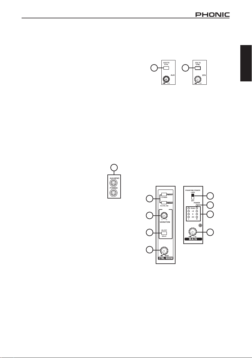
22. Effects On Button (AM105FX and AM125FX only)
Pushing this button will turn the built-in effect
processor on and off.
23. Variation Control (AM105FX and AM125FX only)
This LED indicator will illuminate when the EFX
signal hits high peaks, just before overload occurs.
It is best to adjust the EFX to Main control so as to
ensure the Peak indicator does not light up.
28. AUX/EFX to CTRL Button (AM125 and
AM125FX only)
Pushing this button will send the signal from the AUX
or EFX mix to the Control Room mix. This is useful
for monitoring of the EFX mix or for the tracking of
individual instruments.
28 28
English
Master Section
24. 2T Return Controls
Pushing either one of the buttons in the 2T Return
Control Section selects the destination of the 2T
Return signal. The uppermost button (“to L/R”) sends
the signal to the Main L-R mixing bus, whereas
the lower button (either “to Phones” or “to Ctrl Rm”
) sends the signal to the Phones or Control Room/
Phones mixing bus, respectively. These buttons can,
of course, be used simultaneously, feeding the signal
to both the Control Room/Phones and Main L/R
mixing bus. If the “to Phones” or “to Ctrl Rm” buttons
are not engaged, the Phones and Control Room
outputs will receive the Main L-R signal.
25. AUX / EFX Send Control (AM125
and AM125FX only)
This control adjusts the level of signal,
taken from each individual channel’s AUX
controls, will be sent to the AUX send
output. In the case of the AM125FX, the
EFX control will adjust the level of signal
taken from the built in effect processor to
the EFX send output.
26. Phantom Power Switch
When this switch is in the on position it activates
+48V of phantom power for both microphone inputs,
allowing condenser microphones to be used on
these channels.
NB. Phantom Power should be used in conjunction with
condenser microphones only. However many modern
microphones are unaffected by Phantom Power, so it’s best to
consult your mic’s user’s manual for details.
27. Phones (Control Room/Phones) Control
On the AM55, this control is used to adjust the
audio level of the phones feed, to be sent to the
Phones output. It can be used in conjunction with
headphones or, if required, as an auxiliary output.
On the AM85, AM105, AM105FX, AM125 and
AM125FX, however, this control adjusts not only the
phones level, but the signal level sent to the Control
Room output also. The Control Room output is
commonly used in monitoring, as a side ll, or for the
addition of other, external devices.
25
AM85
AM125
29. Main L/R Control
This control is nal level control for the main left and
right audio feed, sent to the Main L and R output.
30. Level Meter
The AM series’ 4-segment level meters give an
accurate indication of when audio levels of the MAIN
L/R output reach certain levels. It is suggested
for the maximum use of audio to set the various
levels controls so that the peak light ashes only on
occasionally (and perhaps it is better if to leave it a
pinch below this level).
31. Power Indicator
The Power Indicator will light up when the power of
the mixer is on.
24
AM125FX
26
31
23
22
30
29
27
AM55/AM85/AM105/AM105FX/AM125/AM125FX
5
Page 10

SPECIFICATIONS
English
Inputs
Total Channels 3 4 6 6 8 8
Balanced Mono Mic
/ Line channel
Balanced Stereo
Line Channel
Aux Return - 1 stereo - - 2 stereo 2 stereo
2T Input Stereo RCA Stereo RCA Stereo RCA Stereo RCA Stereo RCA Stereo RCA
Outputs
Rec Out Stereo RCA Stereo RCA Stereo RCA Stereo RCA Stereo RCA Stereo RCA
CTRL RM L/R - 2 x 1/4" TS 2 x 1/4" TS 2 x 1/4" TS 2 x 1/4" TS 2 x 1/4" TS
Phones
Channel Strips 3 4 6 6 6 6
Aux Sends - 1 1 1 2 2
Pan/Balance
Control
Channel insert - - - - - 4
Volume Controls Rotary Rotary Rotary Rotary Rotary Rotary
Master Section
Aux Send Masters - - - - Yes Yes
Phones Level
Control
Faders
Metering
Number of
Channels
Segments 4 4 4 4 4 4
Phantom Power
Supply
Switches Master Master Master Master Master Master
Digital Eect
Processor
20Hz ~ 60KHz +0/-1 dB +0/-1 dB +0/-1 dB +0/-1 dB +0/-1 dB +0/-1 dB
20Hz ~ 100KHz +0/-3 dB +0/-3 dB +0/-3 dB +0/-3 dB +0/-3 dB +0/-3 dB
Crosstalk
Channel fader
down, other
channels at unity
Noise
(20Hz~20KHz; measured at main output, Channels 1-4 unit gain; EQ at; all channels on main mix; channels 1/3 as far left
as possible, channels 2/4 as far right as possible. Reference=+6dBu)
Master @ unity,
channel fader down
Master @ unity,
channel fader @
unity
S/N ratio, ref to +4 >90 dB >90 dB >90 dB >90 dB >90 dB >90 dB
AM55 AM85 AM105 AM105FX AM125 AM125FX
1 2 2 2 4 4
2 2 4 4 4 4
1 1
Yes Yes Yes Yes Yes Yes
Yes Yes Yes Yes Yes Yes
Main L & R
(Rotary)
2 2 2 2 2 2
- +48V DC +48V DC +48V DC +48V DC +48V DC
- - -
(1KHz @ 0dBu, 20Hz to 20KHz bandwidth, channel in to main L/R outputs)
<-90 dB <-90 dB <-90 dB <-90 dB <-90 dB <-90 dB
-86.5 dBu -86.5 dBu -86.5 dBu -86.5 dBu -86.5 dBu -86.5 dBu
-84 dBu -84 dBu -84 dBu -84 dBu -84 dBu -84 dBu
Main L & R Main L & R Main L & R Main L & R Main L & R
1 1
1Digital EFX with
one Variation
control
1
-
1
1Digital EFX with
one Variation
control
6
AM55/AM85/AM105/AM105FX/AM125/AM125FX
Page 11

Microphone
Preamp E.I.N.
ohms terminated,
max gain)
THD
1KHz @ +14dBu,
20Hz to 20KHz,
channel inputs)
CMRR
-60dBu, Gain at
maximum)
Maximum Level
Mic Preamp Input +10dBu +10dBu +10dBu +10dBu +10dBu +10dBu
All Other Input +21dBu +21dBu +21dBu +21dBu +21dBu +21dBu
Balanced Output +28dBu +28dBu +28dBu +28dBu +28dBu +28dBu
Impedance
Mic Preamp Input 2 K ohms 2 K ohms 2 K ohms 2 K ohms 2 K ohms 2 K ohms
All Other Input
(except insert)
RCA 2T Output 1.1 K ohms 1.1 K ohms 1.1 K ohms 1.1 K ohms 1.1 K ohms 1.1 K ohms
Ch Equalization 2-band, +/-15 dB 3-band, +/-15 dB 3-band, +/-15 dB 3-band, +/-15 dB 3-band, +/-15 dB 3-band, +/-15 dB
Low EQ 80 Hz 80 Hz 80 Hz 80 Hz 80 Hz 80 Hz
Mid EQ (mono
channel)
Hi EQ 12 KHz 12 KHz 12 KHz 12 KHz 12 KHz 12 KHz
Low cut lter 75Hz (-18 dB/oct) - 75Hz (-18 dB/oct) 75Hz (-18 dB/oct) 75Hz (-18dB/oct) 75Hz (-18dB/oct)
Built-in Power
Supply
Weight
Dimensions
(WxHxD)
(Any output,
(1 KHz @
(150
<-129.5 dBm <-129.5 dBm <-129.5 dBm <-129.5 dBm <-129.5 dBm <-129.5 dBm
<0.005% <0.005% <0.005% <0.005% <0.005% <0.005%
80dB 80dB 80dB 80dB 80dB 80dB
10 K ohms 10 K ohms 10 K ohms 10 K ohms 10 K ohms 10 K ohms
- 2.5 KHz 2.5 KHz 2.5 KHz 2.5 KHz 2.5 KHz
100 VAC, 120
VAC, 220 ~ 240
VAC, 50/60 Hz
1.1 kg (2.4 lbs) 1.5 kg (3.3 lbs) 1.5 kg (3.3 lbs) 1.5 kg (3.3 lbs) 1.7kg (3.75 lbs) 1.72 kg (3.78 lbs)
155.6x50.5x244mm
(6.12"x 99"x 8.82")
100VAC,
120VAC, 220 ~
240VAC, 50/60Hz
190x56x233 mm
(7.48"x2.2"x9.17")
100VAC,
120VAC, 220 ~
240VAC, 50/60Hz
190x56x233 mm
(7.48"x2.2"x9.17")
100VAC,
120VAC, 220 ~
240VAC, 50/60Hz
190x56x233 mm
(7.48"x2.2"x9.17")
100VAC,
120VAC,
220~240VAC,
50/60Hz
242x55x225 mm
(9.5"x2.16"x8.86")
242x55x225 mm
(9.5"x2.16"x8.86")
100VAC,
120VAC,
220~240VAC,
50/60Hz
English
AM55/AM85/AM105/AM105FX/AM125/AM125FX
7
Page 12

English
SERVICE AND REPAIR
For replacement parts, service and repairs please contact the Phonic distributor in your
country. Phonic does not release service manuals to consumers, and advice users to not
attempt any self repairs, as doing so voids all warranties. You can locate a dealer near you at
http://www.phonic.com/where/.
WARRANTY INFORMATION
Phonic stands behind every product we make with a no-hassles warranty. Warranty coverage
may be extended, depending on your region. Phonic Corporation warrants this product for a
minimum of one year from the original date of purchase against defects in material and
workmanship under use as instructed by the user’s manual. Phonic, at its option, shall repair
or replace the defective unit covered by this warranty. Please retain the dated sales receipt as
evidence of the date of purchase. You will need it for any warranty service. No returns or repairs
will be accepted without a proper RMA number (return merchandise authorization). In order to
keep this warranty in effect, the product must have been handled and used as prescribed in the
instructions accompanying this warranty.Any tampering of the product or attempts of self repair
voids all warranty. This warranty does not cover any damage due to accident, misuse, abuse,
or negligence. This warranty is valid only if the product was purchased new from an authorized
Phonic dealer/distributor. For complete warranty policy information, please visit
http://www.phonic.com/warranty/.
CUSTOMER SERVICE AND TECHNICAL SUPPORT
We encourage you to visit our online help at http://www.phonic.com/support/. There you can find
answers to frequently asked questions, tech tips, driver downloads, returns instruction and other
helpful information. We make every effort to answer your questions within one business day.
support@phonic.com
http://ww
w.phonic.com
8
AM55/AM85/AM105/AM105FX/AM125/AM125FX
Page 13

MANUAL DEL USUARIO
CONTENIDO
English Español
INTRODUCCIÓN
CARACTERÍSTICAS
CONFIGURACIÓN INSTANTE
HACIENDO CONEXIONES
CONTROLES Y CONFIGURACIONES
ESPECIFICACIONES
APéNDICE
APLICACIÓN
DIMENSIONES
Phonic se reserva el derecho de mejorar o alterar cualquier información
provista dentro de este documento sin previo aviso.
1
1
2
3
4
7
1
5
AM55/AM85/AM105/AM105FX/AM125/AM125FX
9
Page 14

English Español
10
AM55/AM85/AM105/AM105FX/AM125/AM125FX
Page 15

INTRODUCCIÓN
Felicidades por la compra de una de las muchas
mezcladoras compactas de calidad de Phonic. La
entera serie M de mezcladoras – diseñadas por los
ingenieros talentosos que han creado una variedad
de mezcladoras fantásticas en estilo y funcionamiento en el pasado – muestra capacidad similar
a los productos anteriores de Phonic que han
mostrado; con más que algunos renamientos, por
supuesto. La serie M ofrece rango completo de ganancia, asombroso nivel bajo de distorsión, manejo
de señal de línea a +22 dBu y, rangos dinámicos
increíblemente anchos, apenas muestra la dominación de estas pequeñas máquinas tendrán en el
estudio o lugares en vivo.
Sabemos que está impaciente por comenzar –
queriendo sacar la mezcladora y conectar todo es
probablemente su máxima prioridad ahora – pero
antes de hacerlo, le sugerimos encarecidamente
que tome una mirada a este manual. Adentro, usted
encontrará hechos y figuras importantes sobre la
conguración, uso y aplicaciones de su nueva mezcladora. Si usted resulta ser uno de la mucha gente
que se rechaza rotundamente a leer los manuales
del usuario, entonces le pedimo que por lo menos
eche un vistazo a la sección Conguración Instan te. Después de echar un vistazo o de leer el manual
(le aplaudimos si usted lee el manual entero), por
favor uardelo en un lugar de fácil acceso, porque
es posible que se le haya escapado algo en la primera leida.
CARACTERÍSTICAS
AM55
Preamplicadores de micrófono de calidadaudió-
lo & ruido ultra bajo
1 canal de mic/línea y 2 canales estéreo
EQ de 2-Bandas en canal de entrada mono
2T RTN & 2T REC para grabadora de CD o tape
Medidor de nivel master dual de 4-segmentos
Salida de audífonos con control de volumen
LED de pico en canal de entrada mono
Salida master balanceada
AM85
Calidad-audiólo & ruido ultra bajo
Dos entradas balanceadas de Mic/Línea con EQ
de 3-bandas
Dos entradas estéreo con EQ de 3-bandas
Un retorno aux estéreo
Envío EFX pos-fader en cada entrada
Fuente fantasma a +48V global
Medición de Pico y VU
Indicadores de pico en cada canal de entrada mono
2T RTN asignable individualmente a Main o
Control room
Salida master balanceda
AM55/AM85/AM105/AM105FX/AM125/AM125FX
AM105
Calidad-audiólo & ruido ultra bajo
Dos entradas balanceadas de Mic/Línea con EQ
de 3-bandas y corte bajo
Cuatro entradas estéreo con botón selector de
+4/-10
Envío AUX post-fader en cada entrada
Fuente fantasma a +48V global
Salidas CTRL RM y audífonos
Indicadores de pico en cada canal de entrada mono
Conveniente E/S RCA estéreo
Salida master balanceada
AM105FX
Calidad-audiólo & circuito de ruido ultra bajo
Dos entradas balanceadas de Mic/Línea con EQ
de 3-bandas y corte bajo
Cuatro entradas estéreo con botón selector de
+4/-10
Envío AUX post-fader en cada entrada
Fuente fantasma a +48V global
Salidas CTRL RM y audífonos
Indicadores de pico en cada canal de entrada
mono
Conveniente E/S RCA estéreo
Efecto delay variable con control de variación
Salida master balanceada
AM125
Calidad-Audiólo & ruido ultra bajo
4 canales de mic/línea mono
4 canales estéreo
Envíos AUX en cada canal
Filtro de corte-bajo a 75Hz en canal mono
EQ de 3-bandas en cada canal mono
Fuente fantasma a +48V en canales de micrófo-
no
Matriz fuente de Control room/Phones para máxi-
ma exibilidad de monitoreo
Cue de envío AUX para monitorear canal indivi-
dual
Salida balanceada TRS
AM125FX
Calidad-Audiólo & ruido ultra bajo
4 canales de mic/línea mono
4 canales estéreo
Envíos AUX en cada canal
Filtro de corte bajo a 75Hz en canal mono
EQ de 3-bandas en cada canal mono
Fuente fantasma a +48V en canales de micrófo-
no
Matriz fuente de Control room/Phones para máxi-
ma exibilidad de monitoreo
Cue de envío AUX para monitorear canal indivi-
dual
Efecto delay var iable con cont rol de variación
Salida balanceada TRS
1
English Español
Page 16

CONFIGURACIÓN INSTANTE
Comenzando
1. Asegúrese que toda la corriente esté apagada
English Español
en su mezcladora. Para asegurar totalmente de
esto, el cable AC no se debe conectar a la unidad.
2. Todos los faders y controles de nivel deben ser
seteados en el nivel más bajo y todos los canales
apagados para asegurar que ningún sonido sea
enviado inadvertidamente a través de las salidas
cuando se enciende el dispositivo. Todos los niveles pueden ser alterados a grados aceptables
después de encender el dispositivo.
3. Conecte todos los instrumentos y equipo necesarios en las diversas entradas del dispositivo
como sea necesario. Esto puede incluir dispositivos de señal de línea, tales como teclados y
unidades de ritmos, así como los micrófonos y/o
las guitarras, etc.
4. Conecte cualquier equipo necesario en las diversas salidas de dispositivo. Esto podía incluir am-
plicadores, altavoces, monitores, procesadores
de señal y/o dispositivos de grabación.
5. Conecte el suministro de energía AC a la entrada
en la parte posterior del dispositivo y luego a la
salida de energía de un nivel voltaico conveniente.
6. Encienda el interruptor de energía y siga las
instrucciones de conguración de canal para obtener lo máximo de su equipo.
Conguración de Canal
1. Para garantizar el correcto nivel de audio de
canal de entrada es seleccionado, cada control
de entrada de nivel de la Mezcladora debe ser
girado a más izquierda posible(debe ser -∞).
2. Ninguna otra entrada además de la que está
siendo seteado debe tener dispositivo conectado.
Esto asegurará la señal más pura sea utilizada al
setear los canales.
3. Asegúrese de que el canal tenga señal de envío
similar a la señal que se enviará en uso común.
Por ejemplo, si el canal está utilizando un micrófono, entonces usted debería hablar o cantar al
mismo nivel que el artista lo hace normalmente
durante una actuación; si una guitarra está conectado a canal, entonces la guitarra también
debería utilizarse como es normalmente (y así
sucesivamente). Esto asegura que los niveles
sean totalmente precisos y evita tener que reajustarlos más adelante.
4. Setee la ganancia de tal manera que el medidor de
nivel indicara el nivel de audio alrededor de 0 dB.
5. Este canal está listo ahora para ser utilizado; usted puede parar de hacer la señal de audio.
6. Usted puede repetir el mismo proceso para otros
canales.
2
AM55/AM85/AM105/AM105FX/AM125/AM125FX
Page 17

HACIENDO CONEXIONES
Entradas y Salidas
1. Jacks XLR de Micrófono
Estos jacks aceptan entradas
típicas XLR de 3-pins para
las señ ales balance adas y
desbalanceadas. Pueden ser
utilizados junto con micrófonos
– ta l es co m o m ic r óf o no s
profesionales de condensador,
dinámicos o de cinta – con los
conectores machos estándares XLR y, presentan
preamplificadores de bajo ruido que sirven para
reproducción cristalina clara de los sonidos. Con la
excepción de AM55, cada una de las mezcladoras
de la serie M ofrece dos entradas estándar XLR de
micrófono para su conveniencia.
Nota. Cuando estas entradas son utilizadas con los
micrófonos de condensador, la Fuente Fantasma debe
ser activado. Sin embargo, cuando el botón de Fuente
Fantasma está activado, los micrófonos de simple
terminación (desbalanceado) y los instrumentos no deben ser
utilizados en las entradas Mic al menos que sea aprobado
especicamente por el fabricante de micrófono.
2. Entrada de Línea
Estas entradas aceptan entradas típicas de
1/4” TRS o TS para las señales balanceadas y
desbalanceadas. Pueden ser utilizados junto con
diversos dispositivos de nivel de línea, tales como
teclados, unidades de ritmos, guitarras eléctricas y
una variedad de otros instrumentos eléctricos.
3. Canales Estéreo
Cada mezcladora AM ofrece algunos canales
estéreo para máxima ecibilidad. Cada uno de estos
canales estéreo tiene dos jacks de audífono de 1/4”
para la adición de diversos dispositivos de entrada
de nivel de línea, tales como teclados elécticos,
guitarras y procesadores de señal externos o
mezcladoras. Estos canales estéreo también
pueden ser usados como canales mono, donde
la señal desde cualquier jack de audífono de 1/4”
conectado a la entrada estérea izquierda causará
que se duplica a la entrada derecha también. Sin
embargo, esto no funciona al revés.
4. Salidas Main L y R
Estos dos puertos harán salir la señal de nivel
de línea estérea final enviada de bus de mezcla
principal. El propósito primario de estos jacks es
enviar la salida principal a los dispositivos externos,
que pueden incluir los amplicadores de potencia (y
a su vez un par de altavoces), otras mezcladoras,
así como una amplia gama de otros posibles
procesadores de señal (ecualizadores, crossovers,
etcétera).
1
2
5. Retornos AUX Estéreo (AM85
solamente)
Estas entradas de 1/4” TS son para
el retorno de audio a la mezcladora
AM85, procesado por un procesador
de señal externo. Si es necesario
realmente, también pueden ser
utilizadas como entradas adicionales, con un
control de nivel localizado en la parte frontal de
la mezcladora. El Retorno AUX Estéreo también
puede aceptar señales mono. Como con los canales
de entrada estéreos, estas entradas pueden ser
utilizados como canales mono conectando el
enchufe de audífono 1/4” de cualquier dispositivo
mono en la entrada izquierda de Retorno AUX
Estéreo.
6. Envíos AUX/EFX (AM85, AM105, AM105FX,
AM125 y AM125FX solamente)
Estas salidas de 1/4” TS pueden ser utilizados para
conectar a procesador de efecto digital externo o
incluso a un amplicador y altavoces (dependiendo
de sus conguraciones deseadas) a la mezcladora.
La señal es tomada desde control AUX en cada
canal de entrada. En AM105FX y AM125FX, la señal
enviada desde esta salida es tomada de motor de
efecto integrado. Esta salida se presenta solamente
en las mezcladoras AM85, AM105, AM105FX,
AM125 y AM125FX, por lo tanto no la encontrará en
AM55.
7. Audífonos
Estos puertos de salida estéreos son aptos para
el uso con los audífonos, permitiendo el monitoreo
de la mezcla. El nivel de audio de esta salida
es controlado usando el control de Audífonos o
Audífonos/Control Room.
8. Salidas de Grabación 2T
/ Grabación
Estas salidas acomodarán los
cables de RCA, capaces de ser
alimentado a una variedad de
dispositivos de grabación.
9. Retorno 2T
Estas entradas RCA son utilizadas para conectar la
mezcladora con dispositivos externos paralelos, tales
como sub mezcladoras o procesadores de efecto
externos, recibiendo la señal procesada desde otra
fuente y alimentandola a bus de mezcla Principal I y
D o Audífonos.
10
3
AM85
5
8
9
4
6
7
English Español
AM55/AM85/AM105/AM105FX/AM125/AM125FX
3
Page 18

10. Salidas de Control Room (AM85, AM105,
AM105FX, AM125 y AM125FX solamente)
Estas dos salidas de jack de audífono de 1/4”
alimentan la señal alterada por el control de nivel
English Español
de Control Room/Audífonos en la parte frontal de la
mezcladora. Esta salida tiene uso extenso, puede
ser utilizada para alimentar la señal de la mezcladora
a un monitor activo, para monitorear la señal de
audio dentro de una cabina, o alternativamente,
para la adición de dispositivos de procesamiento de
señal o mezcladoras, también se actúa como salida
“side fill”, suministrando audio a áreas interiors
que los altavoces principales no llegan. Esta salida
se presenta en las mezcladoras AM85, AM105,
AM105FX, AM125 y AM125FX solamente.
Panel Posterior
11. Conector de Energía
Este puerto es para la adición de
fuente de energía externa, permiendo
que la energía sea sumins t rada a la
mezcladora. Por favor ut i l ice la unidad
de suministro de energía incluida en la
mezcladora solamente.
11
CONTROLES Y
CONFIGURACIONES
Controles de Canal
12. Control de Ganancia de Línea/Micrófono
Esto controla la sensibilidad de la señal de entrada
de Línea/Micrófono. La ganancia debe ser ajustado
a un nivel que permite el uso máximo del audio,
mientras sigue manteniendo la cal idad de la
alimentación. Esto puede ser logrado ajustándolo
a un nivel que permite que el indicador de pico se
ilumine ocasionalmente. La AM55 ofrece un solo
control de ganancia para canal 1, localizado en la
parte frontal de la mezcladora, mientras que las
AM85, AM105 y AM105FX todas tienen controles
de ganancia en ambos canales 1 y 2, situados
directamente debajo de las entradas de Línea. Las
AM125 y AM125FX presentan controles de ganancia
en los canales de 1 a 4.
13. Control de Frecuencia
Alta
Este control es utilizado para dar
un aumento tipo shelving o un
corte de ±15 dB a los sonidos
de alta frecuencia (12 kHz). Esto
ajustará la cantidad de agudos
incluido en el audio del canal,
añadiendo fuerza y claridad a
los sonidos tales como guitarras,
platillos y sintetizadores.
14. Filt ro de C ort e Ba jo
(75 Hz) (AM85, AM105,
AM 1 0 5 F X , A M 12 5 y
AM125FX solamente)
Este botón activará un filtro de
paso-alto que reduce todas las frecuencias debajo
de 75 Hz a 18 dB por octava, ayudando a remover
cualquier ruido de tierra o estruendo indeseado de
escenario. Este botón puede ser encontrado en los
canales mono de AM85, AM105, AM105FX, AM125 y
AM125FX solamente.
15. Control de Frecuencia Media (AM85, AM105
y AM105FX solamente)
Este control es utilizado para proporcionar un estilo
pico de aumento y corte a nivel de sonidos de
frecuencia media en un rango de ±15 dB. Cambiar
las frecuencias medias de una alimentación de
audio puede ser algo difícil cuando se utiliza en una
mezcla de audio profesional, ya que a menudo es
más deseable cortar sonidos de frecuencia media
más que aumentarlos - calmando excesivamente
voces ásperos y sonidos de instrumento en el audio.
16. Control de Frecuencia Baja
Este control es utilizado para dar un aumento
shelving o corte de ±15 dB a los sonidos de
frecuencia baja (80 Hz). Esto ajustará la cantidad
de bajo incluido en el audio del canal y brinda más
calidez y fuerza a los tambores y a las guitarras
bass.
17. Cont rol es AU X/EF X (A M85 , AM1 05,
AM105FX, AM125 y AM125FX solamente)
Estos controles alteran el nivel de señal que es
enviada a los Envíos AUX o EFX que puede ser
utilizado junto con procesadores de señal externos o
simplemente como una salida auxiliar para muchas
necesidades. En AM105FX y AM125FX, el control
EFX es utilizado para alterar el nivel de la señal que
es enviada a la mezcla interna de efectos.
13
15
16
14
17
19
21
20
12
4
AM55/AM85/AM105/AM105FX/AM125/AM125FX
Page 19

18. Interruptor +4 / -10 (AM85, AM105, AM105FX,
AM125 y AM125FX solamente)
Este interruptor es utilizado para ajustar la
sensibilidad de los canales correspondientes,
que adaptará la mezcladora a los dispositivos
externos que pueden utilizar diferentes niveles de
operación. Si la fuente de entrada es -10 dBV, es
mejor activar el interruptor, permitiendo que la señal
sea oída. El modo +4 dBu es conveniente para
usar con las señales de nivel de audio profesional,
que son considerablemente más altas que las de
nivel del consumidor. Si usted está inseguro del
nivel de operación de la fuente, sugerimos dejar
el interruptor desactivado hasta que usted testee
la señal de fuente. Usted puede activarlo luego en
caso necesario (si el nivel de entrada es obviamente
demasiado bajo).
19. Controles de Pan / Balance
Esto alterna el grado o el nivel de audio que el lado
izquierdo y derecho de la mezcla principal debe
recibir. En los canales mono, este control ajustará el
nivel que el izquierdo y derecho deben recibir (pan),
como en un canal estéreo, ajustando el control BAL
atenuará las señales de audio izquierdas o derechas
como corresponde (balance). Cada modelo presenta
un control de PAN o BAL en cada una de sus tiras
de canal.
20. Indicador de Pico
Este indicador de LED iluminará cuando el
dispositivo alcanza a picos altos, 6 dB antes de que
ocurra la sobrecarga. Es mejor ajustar la ganancia
de canal de modo tal que el indicador de PICO se
enciende en intervalos. Esto asegurará un mayor
rango dinámico de audio. El indicador de Pico se
presenta en los canales mono de cada modelo.
21. Control de Nivel
Este control alterará el nivel de la señal que es
enviada desde canal correspondiente a bus de
mezcla principal.
13
15
16
18
14
17
19
21
20
Sección de Efectos
22. B o tó n de E n ce nd i do
de Efectos (AM105FX y
AM125FX solamente)
Pulsando este botón encenderá y
apagará el procesador de efecto
integrado.
23. C o n tr ol d e V a r i ac ió n
(AM105FX y AM125FX
solamente)
Este indicador LED se iluminará
cuando la señal EFX alcanza a
picos altos, justo antes de que
ocurra la sobrecarga. Es mejor
ajustar el control de EFX a Main
para asegurar que el indicador de
Pico no se encienda.
24
23
22
27
Sección Master
24. Controles de Retorno 2T
Pulsando cualquiera de los botones en la Sección de
Control de Retorno 2T se selecciona el destino de
la señal de Retorno 2T. El botón más arriba (“to L/R”
) envía la señal a bus de mezcla Main L-R, mientras
que el botón más bajo (“to Phones” o “to Ctrl Rm”
) envía la señal a bus de mezcla de Audífonos o
Control Room/Audífonos, respectivamente. Estos
botones pueden, por supuesto, ser utilizados
simultaneamente, alimentando la señal a ambos
buses de mezcla de Control Room/Audífonos y Main
L/R. Si los botones “to Phones” o “to Ctrl Rm” no
están activados, las salidas de Audífonos y Control
Room recibirán la señal de Main L-R.
25. Control de Envío AU X / EF X
(AM125 y AM125FX solamente)
Este control ajusta el nivel de la señal
tomada desde cada control AUX de canal
individual, será enviada a la salida de
envío AUX. En el caso de AM125FX,
el control de EFX ajustará el nivel de la
señal tomoda desde procesador de efecto
integrado a la salida de envío EFX.
26. Interruptor de Fuente Fantasma
Cuando este interruptor está en la posición de
encendido, activa +48V de fuente fantasma para
ambas entradas de micrófono, permitiendo que los
micrófonos de condensador sean utilizados en estos
canales.
Nota. La Fuente Fantasma se debe utilizar junto con los
micrófonos de condensador solamente. Sin embargo,
muchos micrófonos modernos son inafectados por la Fuente
Fantasma, es mejor consultar el manual del usuario de su
micrófono para los detalles .
25
AM85
English Español
AM55/AM85/AM105/AM105FX/AM125/AM125FX
5
Page 20

27. Control de Audífonos (Control Room/
Audífonos)
En la AM55, este control es utilizado para ajustar el
nivel de audio de la alimentación de audífonos para
English Español
ser enviado a la salida de Audífonos. Puede ser
utilizado junto con audífonos o si es necesario como
una salida auxiliar. Sin embargo, en AM85, AM105,
AM105FX, AM125 y AM125FX, este control ajusta
no solo el nivel de audífonos, sino también el nivel
de la señal enviada a la salida de Control Room. La
salida de Control Room es comunmente usada en
el monitoreo, como side ll o para adición de otros
dispositivos externos.
28. Bot ón de A U X/EFX a CT RL (AM 125 y
AM125FX solamente)
Pulsando este botón enviará la señal de la mezcla
AUX o EFX a la mezcla de Control Room. Esto es
útil para monitorear la mezcla de EFX o para el
seguimiento de instrumentos individuales.
29. Control Main L/R
Este control es el control de nivel final para la
alimentación de audio izquierda y derecha, enviada
a salida Principal I y D.
30. Medidor de Nivel
Los medidores de nivel de 4-segmentos de la serie
AM da una indicación precisa de cuando los niveles
de audio de la salida MAIN L/R alcanza a ciertos
niveles. Se sugiere para el uso máximo de audio
setear los diversos controles de nivel de modo que
la luz de pico destelle solamente en ocasiones (y
quizás es mejor dejarlo un poco debajo de este
nivel).
31. Indicador de Energía
Este Indicador de Energía se encenderá cuando la
energía de la mezcladora está prendido.
26
31
30
29
6
AM55/AM85/AM105/AM105FX/AM125/AM125FX
Page 21

ESPECIFICACIONES
AM55 AM85 AM105 AM105FX AM125 AM125FX
Entradas
Canales Totales 3 4 6 6 8 8
Canal Balanceado
Mono de Mic/Línea
Canal de Línea
Balanceado Estéreo
Retorno Aux - 1 estéreo - - 2 estéreo 2 estéreo
Entrada 2T Estéreo RCA Estéreo RCA Estéreo RCA Estéreo RCA Estéreo RCA Estéreo RCA
Salidas
Salida de Grabación Estéreo RCA Estéreo RCA Estéreo RCA Estéreo RCA Estéreo RCA Estéreo RCA
CTRL RM L/R - 2 x 1/4" TS 2 x 1/4" TS 2 x 1/4" TS 2 x 1/4" TS 2 x 1/4" TS
Audífonos 1 1 1 1 1 1
Tiras de Canal 3 4 6 6 6 6
Envíos Aux - 1 1 1 2 2
Control de Pan/
Balance
Insert de Canal - - - - - 4
Controles de
Volumen
Sección Master
Envío Aux Masters - - - - Sí Sí
Control de Nivel de
Audífonos
Deslizadores
Medición
Número de Canales 2 2 2 2 2 2
Segmentos 4 4 4 4 4 4
Suministro de
Fuente Fantasma
Interruptores Master Master Master Master Master Master
Procesador de
Efecto Digital
20Hz ~ 60KHz +0/-1 dB +0/-1 dB +0/-1 dB +0/-1 dB +0/-1 dB +0/-1 dB
20Hz ~ 100KHz +0/-3 dB +0/-3 dB +0/-3 dB +0/-3 dB +0/-3 dB +0/-3 dB
Diafonía (1KHz @ 0dBu, 20Hz a 20KHz ancho de banda, entrada de canal a salidas main L/R)
Fader de canal
bajo, otros canales
en unidad
Ruido (20Hz - 20KHz; medido en la salida principal, Canales 1-4 ganancia de unidad; EQ at; todos los canales en mezcla
principal; canales 1/3 tan a la izquierda como sea posible, canales 2/4 tan a la derecha como sea posible. Referencia=+6dBu)
Master @ unidad,
deslizadores de
canal bajo
Master @ unidad,
deslizadores e
canal @ unidad
Relación S/R ref a
+4
1 2 2 2 4 5
2 2 4 4 4 4
Sí Sí Sí Sí Sí Sí
Giratorio Giratorio Giratorio Giratorio Giratorio Giratorio
Sí Sí Sí Sí Sí Sí
Main L&R
(Rotatorio)
- +48V DC +48V DC +48VDC +48VDC +48V DC
- - -
<-90 dB <-90 dB <-90 dB <-90 dB <-90 dB <-90 dB
-86.5 dBu -86.5 dBu -86.5 dBu -86.5 dBu -86.5 dBu -86.5 dBu
-84 dBu -84 dBu -84 dBu -84 dBu -84 dBu -84 dBu
>90 dB >90 dB >90 dB >90 dB >90 dB >90 dB
Main L&R Main L&R Main L&R Main L&R Main L&R
1 EFX Digital
con un control de
Variación
-
1 EFX Digital
con un control de
Variación
English Español
AM55/AM85/AM105/AM105FX/AM125/AM125FX
7
Page 22

Preamp de
English Español
Micrófono
E.I.N (150 ohms
terminado, máx
ganancia)
THD (Cualquier
salida, 1KHz @
+14dBu, 20Hz a
20KHz entradas de
canal)
CMRR (1 KHz @
-60dBu, ganancia a
máx.)
Nivel Máximo
Entrada de Preamp
de Mic
Todas otras
entradas
Salidas
Balanceadas
Impedancia
Entrada de Preamp
de Mic
Todas otras
entradad (excepto
inserción)
Salida RCA 2T 1.1 K ohms 1.1 K ohms 1.1 K ohms 1.1 K ohms 1.1 K ohms 1.1 K ohms
Ecualización de
Canal
EQ Bajo 80 Hz 80 Hz 80 Hz 80 Hz 80 Hz 80 Hz
EQ Medio (canal
mono)
EQ Alto 12 KHz 12 KHz 12 KHz 12 KHz 12 KHz 12 KHz
Filtro de Corte Bajo 75Hz (-18 dB/oct) - 75Hz (-18 dB/oct) 75Hz (-18 dB/oct) 75Hz (-18dB/oct) 75Hz (-18dB/oct)
Fuente de
Alimentación
Integrada
Peso 1.1 kg (2.4 lbs) 1.5 kg (3.3 lbs) 1.5 kg (3.3 lbs) 1.5 kg (3.3 lbs) 1.7kg (3.75 lbs) 1.72 kg (3.78 lbs)
Dimensiones
(AnxAlxP)
<-129.5 dBm <-129.5 dBm <-129.5 dBm <-129.5 dBm <-129.5 dBm <-129.5 dBm
<0.005% <0.005% <0.005% <0.005% <0.005% <0.005%
80dB 80dB 80dB 80dB 80dB 80dB
+10dBu +10dBu +10dBu +10dBu +10dBu +10dBu
+21dBu +21dBu +21dBu +21dBu +21dBu +21dBu
+28dBu +28dBu +28dBu +28dBu +28dBu +28dBu
2 K ohms 2 K ohms 2 K ohms 2 K ohms 2 K ohms 2 K ohms
10 K ohms 10 K ohms 10 K ohms 10 K ohms 10 K ohms 10 K ohms
2-band, +/-15 dB 3-band, +/-15 dB 3-band, +/-15 dB 3-band, +/-15 dB 3-band, +/-15 dB 3-band, +/-15 dB
- 2.5 KHz 2.5 KHz 2.5 KHz 2.5 KHz 2.5 KHz
100 VAC, 120
VAC, 220 ~ 240
VAC, 50/60 Hz
155.6x50.5x244mm
(6.12"x 99"x 8.82")
100VAC, 120VAC,
220 ~ 240VAC,
50/60Hz
190x56x233 mm
(7.48"x2.2"x9.17")
100VAC, 120VAC,
220 ~ 240VAC,
50/60Hz
190x56x233 mm
(7.48"x2.2"x9.17")
100VAC, 120VAC,
220 ~ 240VAC,
50/60Hz
190x56x233 mm
(7.48"x2.2"x9.17")
100VAC, 120VAC,
220~240VAC,
50/60Hz
242x55x225 mm
(9.5"x2.16"x8.86")
100VAC, 120VAC,
220~240VAC,
50/60Hz
242x55x225 mm
(9.5"x2.16"x8.86")
8
AM55/AM85/AM105/AM105FX/AM125/AM125FX
Page 23

SERVICIO Y REPARACIÓN
Para refacciones de reemplazo y reparaciones, por favor póngase en contacto con nuestro
distribuidor de Phonic en su país. Phonic no distribuye manuales de servicio directamente a los
consumidores y,avisa a los usuarios que no intenten hacer cualquier reparación por si mismo,
haciendo ésto invalidará todas las garantías del equipo. Puede encontrar un distribuidor cerca
de usted en http://www.phonic.com/where/.
INFORMACIÓN DE LA GARANTIA
Phonic respalda cada producto que hacemos con una garantía sin enredo. La cobertura de
garantía podría ser ampliada dependiendo de su región. Phonic Corporation garantiza este
producto por un mínimo de un año desde la fecha original de su compra, contra defectos en
materiales y mano de obra bajo el uso que se instruya en el manual del usuario. Phonic, a su
propia opinión, reparará o cambiará la unidad defectuosa que se encuentra dentro de esta
garantía. Por favor, guarde los recibos de venta con la fecha de compra como evidencia de la
fecha de compra. Va a necesitar este comprobante para cualquier servicio de garantía. No se
aceptarán reparaciones o devoluciones sin un número RMA apropiado (return merchandise
autorization). En orden de tener esta garantía válida, el producto deberá de haber sido
manejado y utilizado como se describe en las instrucciones que acompañan esta garantía.
Cualquier atentado hacia el producto o cualquier intento de repararlo por usted mismo,
cancelará completamente esta garantía. Esta garantía no cubre daños ocasionados por
accidentes, mal uso, abuso o negligencia. Esta garantía es válida solamente si el producto fue
comprado nuevo de un representante/distribuidor autorizado de Phonic. Para la información
completa acerca de la política de garantía, por favor visite http://www.phonic.com/warranty/.
SERVICIO AL CLIENTE Y SOPORTE TÉCNICO
Le invitamos a que visite nuestro sistema de ayuda en línea en www.phonic.com/support/. Ahí
podrá encontrar respuestas a las preguntas más frecuentes, consejos técnicos, descarga de
drivers,
instrucciones de devolución de equipos y más información de mucho interés. Nosotros
haremos todo el esfuerzo para contestar sus preguntas lo antes posible.
support@phonic.com
http://www.phonic.com
English Español
AM55/AM85/AM105/AM105FX/AM125/AM125FX
9
Page 24

APPLICATION
TECLADO O SINTETIZADOR
GUITARRA BASS
AUDÍFONOS
MONITORESACTIVOS
呺ܟ亢
䋱ৌ
᳝⑤ⲥ䷇ㆅ
䬂ⲬФ఼ড়៤఼
༈᠈ᓣ㘇ᴎ
On the following few pages you will nd a wide range of possible uses for the AM Mixers. Of course these are
Appendix Apéndice
far from the only applications that can be attributed to the mixers’ use; however they should give you an idea
of the possible uses that the various inputs and outputs have. The right combination of microphones, guitars,
drum machines, keyboards, as well as recording devices, signal processors, ampliers and speakers, can make
for the perfect live performance, home studio recording session or even a basic public address, to name a few
possibilities.
APLICACIÓN
En las siguientes pocas páginas usted encontrará un amplio rango de las posibles aplicaciones para las
mezcladoras M. Por supuesto éstos están lejos de ser las únicas aplicaciones que se pueden atribuir al uso
de las mezcladoras, sin embargo, deben darle una idea de las aplicaciones posibles que las diversas entradas
y salidas tienen. La combinación correcta de micrófonos, guitarras, unidades de ritmos, teclados, así como
de dispositivos de grabación, procesadores de señal, amplificadores y altavoces, puede hacerse para un
funcionamiento en vivo perfecto, sesión de grabación de estudio hogareño o incluso una megafonía básica, por
nombrar algunas posibilidades.
Recording Application Aplicación de Grabación
AM55
1
AM55/AM85/AM105/AM105FX/AM125/AM125FX
Page 25

Live Sound Application
TECLADO O SINTETIZADOR
GUITARRA BASS
AUDÍFONOS
MONITORESACTIVOS
GRABADORA DE TAPE
TAPE RECORDER
REPRODUCTOR DE CD
MIC MIC
BASS GUITAR
ACTIVE MONITORS
HEADPHONES
KEYBOARD OR SYNTHESIZER
呺ܟ亢
呺ܟ亢
᳝⑤ⲥ䷇ㆅ
ᔩ䷇ᴎ
䬂ⲬФ఼ড়៤఼
䋱ৌ
༈᠈ᓣ㘇ᴎ
CD᪁ᬒ఼
Aplicación de Sonido en Vivo
Appendix Apéndice
AM85
AM55/AM85/AM105/AM105FX/AM125/AM125FX
2
Page 26

Using an External Signal Processor with AM85
PROCESADOR DE EFECTO
ᬜᵰ໘⧚఼
Appendix Apéndice
Usando un Procesador de Señal Externo con AM85
3
AM85
AM55/AM85/AM105/AM105FX/AM125/AM125FX
Page 27

MIC
GUITAR
GUITARRA
ACTIVE MONITORS
MONITORES ACTIVOS
SPEAKERS
ALTAVOCES
AMPLIFIER
AMPLIFICADOR
EFX PROCESSOR
PROCESADOR DE
EFECTOS(EFX)
DRUM
MACHINE
KEYBOARD
TECLADOS
呺ܟ亢
ঢ়Ҫ
᳝⑤ⲥ䷇ㆅ
䷇ㆅ
ࡳᬒ
䬂ⲬФ఼
哧ໄӓⳳ఼
ᬜᵰ໘⧚఼
Appendix Apéndice
AM55/AM85/AM105/AM105FX/AM125/AM125FX
AM105
4
Page 28

DIMENSION DIMENSION
Appendix Apéndice
AM55
measurements are shown in mm/inches
Todas las medidas están mostradas en mm/pulgadas.
5
AM55/AM85/AM105/AM105FX/AM125/AM125FX
Page 29

AM85
Appendix Apéndice
measurements are shown in mm/inches
Todas las medidas están mostradas en mm/pulgadas.
AM55/AM85/AM105/AM105FX/AM125/AM125FX
6
Page 30

Appendix Apéndice
AM105 / AM105FX
measurements are shown in mm/inches
Todas las medidas están mostradas en mm/pulgadas.
7
AM55/AM85/AM105/AM105FX/AM125/AM125FX
Page 31

AM125 / AM125FX
Appendix Apéndice
measurements are shown in mm/inches
Todas las medidas están mostradas en mm/pulgadas.
AM55/AM85/AM105/AM105FX/AM125/AM125FX
8
Page 32

 Loading...