

Page 1
ユーザーズマニュアル
使用手册
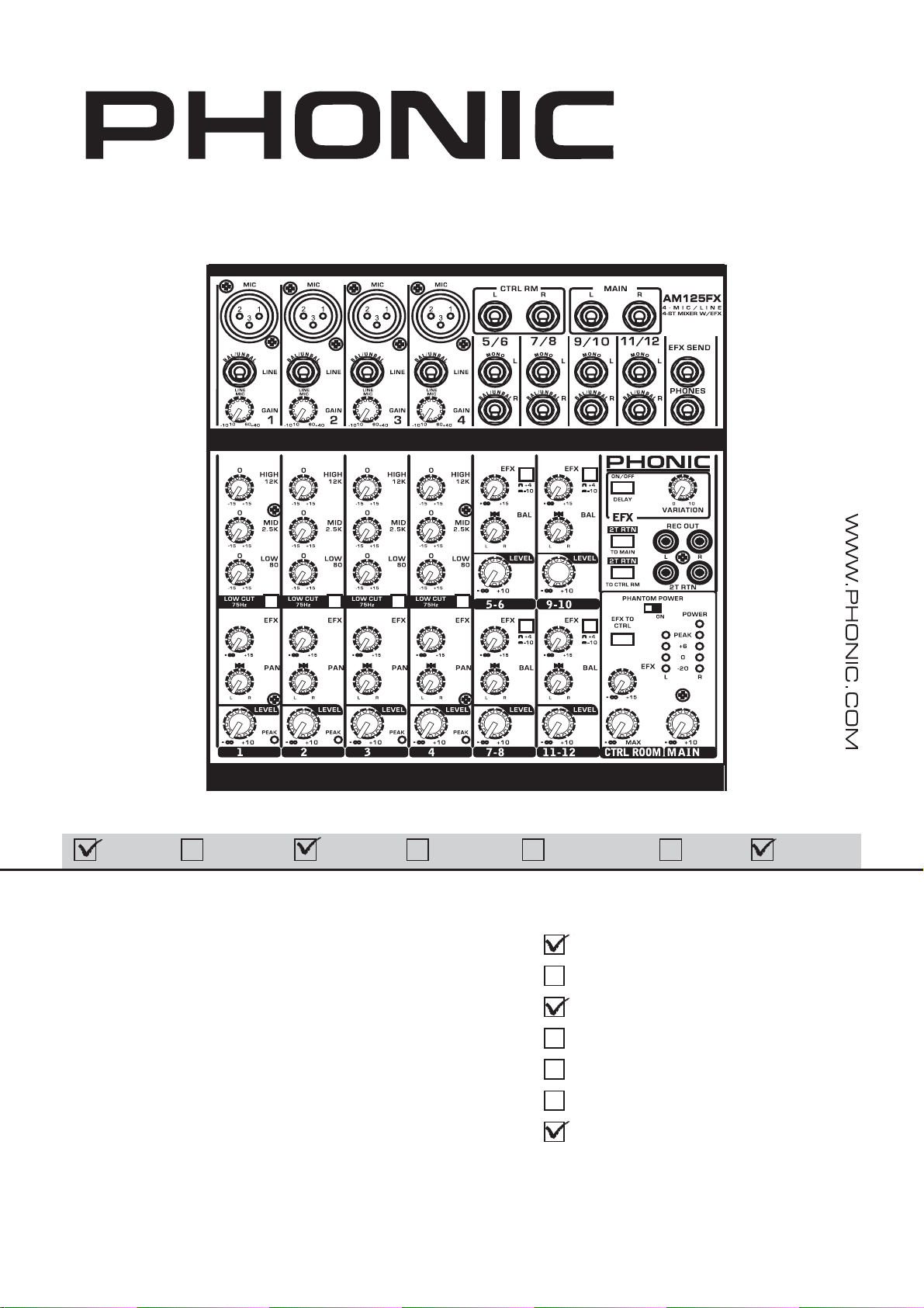
AM125FX
English Deutsch Español Français Português
User's Manual
AM55/AM85/
AM105/AM105FX/
AM125/AM125FX
Benutzerhandbuch
Manual del Usuario
Mode d'emploi
Manual do Usuário
ユーザーズマニュアル
使用手册
日本語
简体中文
Page 2

English Deutsch Español Français Português
日本語
简体中文
AM55/AM85/
AM105/AM105FX/
AM125/AM125FX
COMPACT MIXERS
MEZCLADORA COMPACTAS
便携式调音台
日本語
简体中文
ENGLISH
ESPAÑOL
简体中文
V2.2 08/24/2011
I
II
III
Page 3

USER´S MANUAL
日本語
简体中文
CONTENTS
INTRODUCCION. ....................................................................1
FEATURES...............................................................1
INSTANT SETUP................................................2
MAKING CONNECTIONS.....................................................3
CONTROLS AND SETTINGS..................................4
SPECIFICATIONS...........................................................6
APPENDIX
APPLICACTION .................................................................1
DIMENSION......................................................................5
BLOCK DIAGRAM........................................................9
English Deutsch Español Français Português
Phonic preserves the right to improve or alter any information within this document without prior
notice.
日本語
简体中文
Page 4
English Deutsch Español Français Português
日本語
简体中文
日本語
简体中文
2 AM55/AM85/AM105/AM105FX/AM125/AM125FX
Page 5

日本語
简体中文
INTRODUCTION
Congratulations on purchasing one of Phonic’s many quality
compact mixers. The entire AM series of mixers – designed
by the ingenious engineers that have created a variety of
mixers fantastic in style and performance in the past – displays
similar proficiency that previous Phonic products have shown;
with more than a few refinements, of course. The AM series
features full gain ranges, amazingly low distortion levels, +22
dBu line signal handling, and incredibly wide dynamic ranges,
just showing the dominance these small machines will have in
the studio or live venues.
We know how eager you are to get started – wanting to get
the mixer out and hook it all up is probably your number one
priority right now – but before you do, we strongly urge you to
take a look through this manual. Inside, you will find important
facts and figures on the set up, use and applications of your
brand new mixer. If you do happen to be one of the many
people who flatly refuse to read user manuals, then we just
urge you to at least glance at the Instant Setup section. After
glancing at or reading through the manual (we applaud you if
you do read the entire manual), please store it in a place that
is easy for you to find, because chances are there’s something
you missed the first time around.
FEATURES
AM55
z Audiophile-quality mic preamps & ultra low noise
z 1 mic/line and 2 stereo channels
z 2-Band EQ on mono input channel
z 2T RTN & 2T REC for CD or tape recorder
z Dual 4-segment master level meter
z Headphones output with volume control
z Peak LED on mono input channel
z Balanced master output
AM85
z Audiophile-quality & ultra low noise
z Two balanced Mic/Line inputs with 3-band EQ
z Two stereo inputs with 3-band EQ
z One stereo aux return
z Post-fader EFX send on every input
z Global +48V phantom power
z Peak and VU Metering
z Peak indicators on each mono input channel
z 2T RTN assignable individually to Main or Control room
z Balanced master output
AM105
z Audiophile-quality & ultra low noise
z Two balanced Mic/Line inputs with 3-band EQ and low cut
z Four stereo inputs with +4/-10 select button
z Post-fader AUX send on every input
z Global +48V Phantom Power
z CTRL RM and headphones outputs
z Peak indicators on each mono input channel
z Convenient RCA stereo I/O
z Balanced master output
AM105FX
z Audiophile-quality & ultra low noise circuitry
z Two balanced Mic/Line inputs with 3-band EQ and low cut
z Four stereo inputs with +4/-10 select button
z Post-fader AUX send on every input
z Global +48V Phantom Power
z CTRL RM and headphones outputs
z Peak indicators on each mono input channel
z Convenient RCA stereo I/O
z Variable delay effect with variation control
z Balanced master output
AM125
z Audiophile-Quality & ultra low noise
z 4 mono mic/line channels
z 4 stereo channels
z AUX sends on each channel
z 75Hz low-cut filter on mono channel
z 3-band EQ on each mono channel
z +48V phantom power on mic channels
z Control room/Phones source matrix for maximum monitor
flexibility
z AUX send cue for monitoring individual channel
z Balanced TRS output
AM125FX
z Audiophile-Quality & ultra low noise
z 4 mono mic/line channels
z 4 stereo channels
z AUX sends on each channel
z 75Hz low-cut filter on mono channel
z 3-band EQ on each mono channel
z +48V phantom power on mic channels
z Control room/Phones source matrix for maximum monitor
flexibility
z AUX send cue for monitoring individual channel
z Variable delay effect with variation control
z Balanced TRS output
English Deutsch Español Français Português
日本語
简体中文
1AM55/AM85/AM105/AM105FX/AM125/AM125FX
Page 6

日本語
简体中文
INSTANT SETUP
Getting Started
English Deutsch Español Français Português
1. Ensure all power is turned off on your mixer. To totally ensure
this, the AC cable should not be connected to the unit.
2. All faders and level controls should be set at the lowest
level and all channels switched off to ensure no sound is
inadvertently sent through the outputs when the device is
switched on. All levels can be altered to acceptable degrees
after the device is turned on.
3. Plug all necessary instruments and equipment into the
device’s various inputs as required. This may include line
signal devices, such as keyboards and drum machines, as
well as microphones and/or guitars, keyboards, etc.
4. Plug any necessary equipment into the device’s various
outputs. This could include amplifiers and speakers,
monitors, signal processors, and/or recording devices.
5. Plug the supplied AC power supply into the inlet on the
rear of the device and then into a power outlet of a suitable
voltage.
6. Turn the power switch on and follow the channel setup
instructions to get the most out of your equipment.
Channel Setup
1. To ensure the correct audio level of the input channel is
selected, each of the level input controls of the Mixer should
be turned counterclockwise as far as they will turn (which
should be the -∞ mark).
2. No input other than the one being set should have any
device plugged in. This will ensure the purest signal is used
when setting channels.
3. Ensure the channel has a signal sent to it similar to the
signal that will be sent when in common use. For example, if
the channel is using a microphone, then you should speak or
sing at the same level the performer normally would during a
performance; if a guitar is plugged into the channel, then the
guitar should also be strummed as it normally would be (and
so on). This ensures levels are completely accurate and
avoids having to reset them later.
4. Set the gain so the level meter indicates the audio level is
around 0 dB.
5. This channel is now ready to be used; you can stop making
the audio signal.
6. You can repeat the same process for other channels.
日本語
简体中文
2 AM55/AM85/AM105/AM105FX/AM125/AM125FX
Page 7
日本語
简体中文
MAKING CONNECTIONS
Inputs and Outputs
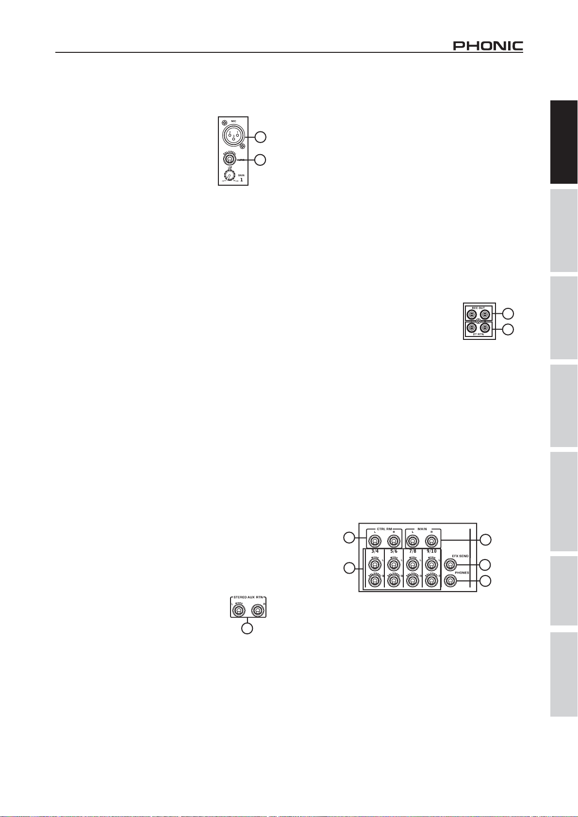
1. XLR Microphone Jacks
These jacks accept typical 3-pin XLR inputs
for balanced and unbalanced signals. They
can be used in conjunction with microphones
– such as professional condenser, dynamic
or ribbon microphones – with standard XLR
male connectors, and feature low noise
preamplifiers, serving for crystal clear sound
replication. With exception to the AM55, each
of the AM series mixers features two standard XLR microphone
inputs for your convenience.
NB. When these inputs are used with condenser microphones, the
Phantom Power should be activated. However, when Phantom Power
button is engaged, single ended (unbalanced) microphones and
instruments should not be used on the Mic inputs unless specifically
approved by the microphone manufacturer.
1
2
6. AUX/EFX Send (AM85, AM105, AM105FX, AM125
and AM125FX only)
These 1/4” TS outputs may be used to connect to an external
digital effect processor, or even to an amplifier and speakers
(depending on your desired settings) to the mixer. The signal
is taken from the AUX control on each input channel. On the
AM105FX and AM125FX, the signal sent from this output is
taken from the built-in effect engine. This output is only featured
on the AM85, AM105, AM105FX, AM125 and AM125FX mixers;
therefore you shouldn’t go looking for it on the AM55.
7. Phones
This stereo output port is suited for use with headphones, allowing
monitoring of the mix. The audio level of this output is controlled
using the Phones or Phones/Control Room control.
8. 2T Record / Record Out
These outputs will accommodate RCA cables, able to be fed to a
variety of recording devices.
English Deutsch Español Français Português
2. Line Inputs
This input accepts typical 1/4” TRS or TS inputs for balanced or
unbalanced signals. There are various numbers of these inputs
depending which mixer you are using. They can be used in
conjunction with various line level devices, such as keyboards,
drum machines, electric guitars, and a variety of other electric
instruments.
3. Stereo Channels
Each of the AM Mixers feature a few stereo channels, thrown in
for maximum flexibility. Each of these stereo channels features
two 1/4” phone jacks, for the addition of various line level input
devices, such as electronic keyboards, guitars and external
signal processors or mixers. These stereo channels can also be
used as mono channels, where the signal from any 1/4” phone
jack plugged into the left stereo input will cause the signal to
duplicate to the right input also. This does not work in reverse,
however.
4. Main L and R Output
These two ports will output the final stereo line level signal sent
from the main mixing bus. The primary purpose of these jacks is
to send the main output to external devices, which may include
power amplifiers (and in-turn, a pair of speakers), other mixers,
as well as a wide range of other possible signal processors
(equalizers, crossovers, etcetera).
5. Stereo AUX Return (AM85 only)
These 1/4” TS inputs are for the return of audio to
the AM85 mixer, processed by an external signal
processor. If really needed, they can also be used
as additional inputs, with a level control located on
the face of the mixer. The Stereo AUX Return can
also accept mono signals. Like with the stereo input channels,
these inputs can be used as mono channels by plugging the 1/4”
phone plug of any mono device into the Stereo AUX return’s left
input.
AM85
5
9. 2T Return
These RCA inputs are used to connect the
mixer with parallel external devices, such
as sub mixers or external effect processors,
receiving the processed signal from another
source and feeding it to either the Main L
and R or the Phones mixing bus.
8
9
10. Control Room Outputs (AM85, AM105, AM105FX,
AM125 and AM125FX only)
These two 1/4” phone jack outputs feed the signal altered by the
Control Room/Phones level control on the face of the mixer. This
output has extensive use, as it can be used to feed the signal
from the mixer to an active monitor, for the monitoring of the
audio signal from within a booth, or, alternatively, for the addition
of external signal processing devices or mixers, as well as acting
as a “side fill” output, supplying audio to indoor areas that the
main speakers do not reach. This output is featured on the AM85,
AM105, AM105FX, AM125 and AM125FX mixers only.
10
3
4
6
7
日本語
简体中文
3AM55/AM85/AM105/AM105FX/AM125/AM125FX
Page 8
日本語
简体中文
Rear Panel
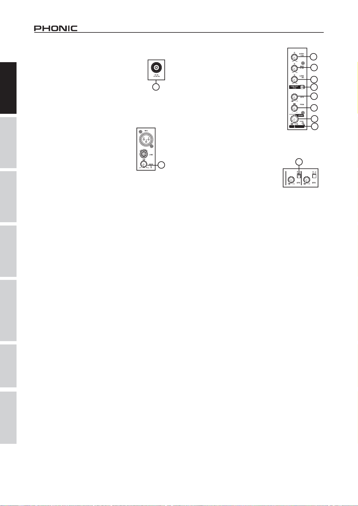
17. AUX/EFX Control (AM85, AM105,
AM105FX, AM125 and AM125FX
11. Power Connector
English Deutsch Español Français Português
This port is for the addition of the external power
supply, allowing power to be supplied to the mixer.
Please use the power supply unit that is included
the mixer only.
with
11
CONTROLS AND SETTINGS
Channel Controls
only)
These controls alter the signal level that is
sent to the AUX or EFX Sends, which can
be used in conjunction with external signal
processors, or simply as an auxiliary output
for any means required. On the AM105FX
and AM125FX, the EFX control is used
to alter the signal level that is sent to the
internal effects mix.
12. Line/Mic Gain Control
This controls the sensitivity of the inputsignal
of the Line/Microphone input. The gain
日本語
should be adjusted to a level that allows
the maximum use of the audio, while still
maintaining the quality of the feed. This can
be accomplished by adjusting it to a level
that will allow the peak indicator occasionally
illuminate. The AM55 features a single gain
control for channel 1, located on the face of
the mixer, whereas the AM85, AM105 and AM105FX all feature
gain controls on both channels 1 and 2, located directly below
the Line inputs. The AM125 and AM125FX feature gain controls
channels 1 through 4.
on
12
13. High Frequency Control
This control is used to give a shelving boost or cut of ±15 dB to
high frequency (12 kHz) sounds. This will adjust the amount of
treble included in the audio of the channel, adding strength and
crispness to sounds such as guitars, cymbals, and synthesizers.
14. Low Cut Filter (75 Hz) (AM85, AM105, AM105FX,
AM125 and AM125FX only)
This button will activate a high pass filter that reduces all
frequencies below 75 Hz at 18 dB per octave, helping to remove
any unwanted ground noise or stage rumble. This button can
be found on mono channels of the AM85, AM105, AM105FX,
AM125 and AM125FX only.
15. Middle Frequency Control (AM85, AM105 and
AM105FX only)
This control is used to provide a peaking style of boost and cut
to the level of middle frequency sounds at a range of ±15 dB.
Changing middle frequencies of an audio feed can be rather
difficult when used in a professional audio mix, as it is usually
more desirable to cut middle frequency sounds rather than boost
them – soothing overly harsh vocal and instrument sounds in
the audio.
18. +4 / -10 Switch (AM85, AM105, AM105FX, AM125
and AM125FX only)
This switch is used adjust the inputsensitivity
of the corresponding channels, which will
adapt the mixer to external devices which
may use different operating levels. If the
inputsource is -10 dBV, it is best to engage
the switch, allowing the signal to be heard.
The +4 dBu mode is suitable for use with professional audio level
signals, which are considerably higher than the consumer level.
If you are unsure of the source’s operating level, we suggest
leaving the switch disengaged until you test the source’s signal.
You can then engage if necessary (if the level of input is obviously
too low).
19. Pan / Balance Controls
This alternates the degree or level of audio that the left and right
side of the main mix should receive. On mono channels, this
control will adjust the level that the left and right should receive
(pan), where as on a stereo channel, adjusting the BAL control
will attenuate the left or right audio signals accordingly (balance).
Each model features a PAN or BAL control on every one of their
channel strips.
20. Peak Indicator
This LED indicator will illuminate when the device hits high peaks,
6 dB before overload occurs. It is best to adjust the gain of the
channel so that the PEAK indicator lights up on intervals. This
will ensure a greater dynamic range of audio. The Peak indicator
is featured on the mono channels of every model.
21. Level Control
This control will alter the signal level that is sent from the
corresponding channel to the main mixing bus.
13
15
16
14
17
19
21
20
18
16. Low Frequency Control
简体中文
This control is used to give a shelving boost or cut of ±15 dB
to low frequency (80 Hz) sounds. This will adjust the amount of
bass included in the audio of the channel, and bring more warmth
and punch to drums and bass guitars.
4 AM55/AM85/AM105/AM105FX/AM125/AM125FX
Effects Section
22. Effects On Button (AM105FX and AM125FX only)
Pushing this button will turn the built-in effect processor on and
off.
23. Variation Control (AM105FX and AM125FX only)
This LED indicator will illuminate when the EFX signal hits high
peaks, just before overload occurs. It is best to adjust the EFX
to Main control so as to ensure the Peak indicator does not light
up.
Page 9

日本語
简体中文
Master Section
24. 2T Return Controls
Pushing either one of the buttons in the 2T Return Control
Section selects the destination of the 2T Return signal. The
uppermost button (“to L/R”) sends the signal to the Main L-R
mixing bus, whereas the lower button (either “to Phones” or
“to Ctrl Rm”) sends the signal to the Phones or Control Room/
Phones mixing bus, respectively. These buttons can, of course,
be used simultaneously, feeding the signal to both the Control
Room/Phones and Main L/R mixing bus. If the “to Phones” or “to
Ctrl Rm” buttons are not engaged, the Phones and Control Room
outputs will receive the Main L-R signal.
29. Main L/R Control
This control is final level control for the main left and right audio
feed, sent to the Main L and R output.
English Deutsch Español Français Português
30. Level Meter
The AM series’ 4-segment level meters give an accurate
indication of when audio levels of the MAIN L/R output reach
certain levels. It is suggested for the maximum use of audio to
set the various levels controls so that the peak light flashes only
on occasionally (and perhaps it is better if to leave it a pinch
below this level).
25. AUX / EFX Send Control (AM125 and
AM125FX only)
This control adjusts the level of signal, taken from
each individual channel’s AUX controls, will be sent
to the AUX send output. In the case of the AM125FX,
the EFX control will adjust the level of signal taken
from the built in effect processor to the EFX send
output.
25
AM85
26. Phantom Power Switch
When this switch is in the on position it activates +48V of
phantom power for both microphone inputs, allowing condenser
microphones to be used on these channels.
NB. Phantom Power should be used in conjunction with condenser microphones only.
This switch is not featured on the AM 55.However many modern microphones are
unaffected by Phantom Power, so it’s best to consult your mic’s user’s manual for
details.
27. Phones (Control Room/Phones) Control
On the AM55, this control is used to adjust the audio level of the
phones feed, to be sent to the Phones output. It can be used
in conjunction with headphones or, if required, as an auxiliary
output. On the AM85, AM105, AM105FX, AM125 and AM125FX,
however, this control adjusts not only the phones level, but the
signal level sent to the Control Room output also. The Control
Room output is commonly used in monitoring, as a side fill, or for
the addition of other, external devices.
31. Power Indicator
The Power Indicator will light up when the power of the mixer
is on.
24
23
22
27
26
31
30
29
28. AUX/EFX to CTRL Button (AM125 and AM125FX
only)
Pushing this button will send the signal from the AUX or EFX mix
to the Control Room mix. This is useful for monitoring of the EFX
mix or for the tracking of individual instruments.
28 28
AM125
AM125FX
日本語
简体中文
5AM55/AM85/AM105/AM105FX/AM125/AM125FX
Page 10

日本語
简体中文
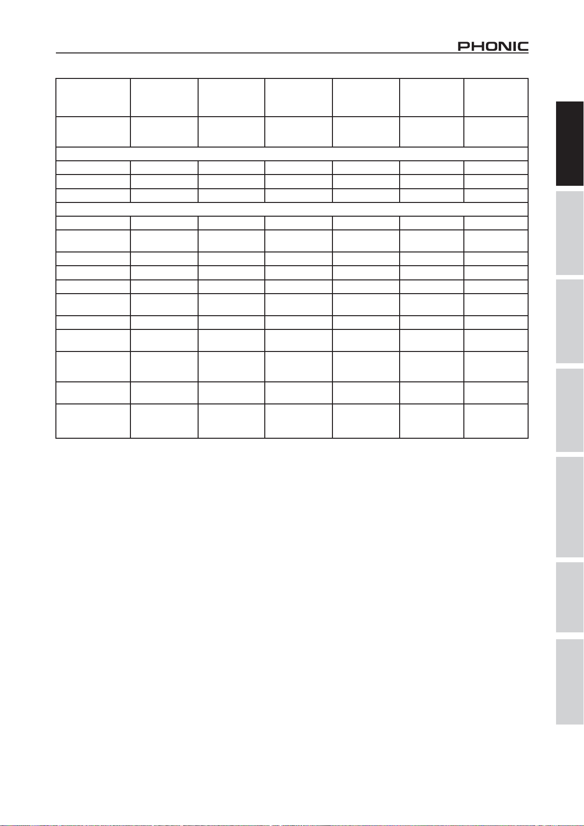
SPECIFICATIONS
English Deutsch Español Français Português
日本語
简体中文
Inputs
Total Channels
Balanced Mono Mic / Line
channel
Balanced Stereo Line Channel 2 4 4 4 4 4
Aux Return - 1 stereo - - 2 stereo 2 stereo
2T Input Stereo RCA Stereo RCA Stereo RCA Stereo RCA Stereo RCA Stereo RCA
Outputs
Main L/R Stereo
Rec Out Stereo RCA Stereo RCA Stereo RCA Stereo RCA Stereo RCA Stereo RCA
CTRL RM L/R - 2 x 1/4" TS 2 x 1/4" TS 2 x 1/4" TS 2 x 1/4" TS 2 x 1/4" TS
Phones 1 1 1 1 1 1
Channel Strips
Aux Sends - 1 1 1 2 2
Pan/Balance Control Yes Yes Yes Yes Yes Yes
Channel insert - - - - - 4
Volume Controls Rotary Rotary Rotary Rotary Rotary Rotary
Master Section
Aux Send Masters
Phones Level Control Yes Yes Yes Yes Yes Yes
Faders
Metering
Number of Channels 2 2 2 2 2 2
Segments 4 4 4 4 4 4
Switches Master Master Master Master Master Master
Digital Effect Processor
20Hz ~ 60KHz +0/-1 dB +0/-1 dB +0/-1 dB +0/-1 dB +0/-1 dB +0/-1 dB
20Hz ~ 100KHz +0/-3 dB +0/-3 dB +0/-3 dB +0/-3 dB +0/-3 dB +0/-3 dB
Crosstalk
Channel fader down, other
channels at unity
Noise
2/4 as far right as possible. Reference=+6dBu)
Master @ unity, channel fader
down
Master @ unity, channel fader @
unity
S/N ratio, ref to +4 >90 dB >90 dB >90 dB >90 dB >90 dB >90 dB
Microphone Preamp E.I.N. (150
ohms terminated, max gain)
(1KHz @ 0dBu, 20Hz to 20KHz bandwidth, channel in to main L/R outputs)
(20Hz~20KHz; measured at main output, Channels 1-4 unit gain; EQ flat; all channels on main mix; channels 1/3 as far left as possible, channels
AM55 AM85 AM105 AM105FX AM125 AM125FX
346 6 8 8
122 2 4 4
2 x 1/4" TRS,
Bal.
346 6 6 6
--- -YesYes
Main L & R
(Rotary)
---
<-90 dB <-90 dB <-90 dB <-90 dB <-90 dB <-90 dB
-86.5 dBu -86.5 dBu -86.5 dBu -86.5 dBu -86.5 dBu -86.5 dBu
-84 dBu -84 dBu -84 dBu -84 dBu -84 dBu -84 dBu
<-129.5 dBm <-129.5 dBm <-129.5 dBm <-129.5 dBm <-129.5 dBm <-129.5 dBm
2 x 1/4" TRS,
Bal.
Main L & R Main L & R Main L & R Main L & R Main L & R
2 x 1/4" TRS,
Bal.
2 x 1/4" TRS, Bal.
1Digital EFX with
one Variation
control
2 x 1/4" TRS,
Bal.
-
2 x 1/4" TRS, Bal.
1Digital EFX with
one Variation
control
6 AM55/AM85/AM105/AM105FX/AM125/AM125FX
Page 11
日本語
简体中文
THD
(Any output,
1KHz @ +14dBu,
20Hz to 20KHz,
channel inputs)
CMRR
(1 KHz @
-60dBu, Gain at
maximum)
Maximum Level
Mic Preamp Input +10dBu +10dBu +10dBu +10dBu +10dBu +10dBu
All Other Input +21dBu +21dBu +21dBu +21dBu +21dBu +21dBu
Balanced Output +28dBu +28dBu +28dBu +28dBu +28dBu +28dBu
Impedance
Mic Preamp Input 2 K ohms 2 K ohms 2 K ohms 2 K ohms 2 K ohms 2 K ohms
All Other Input
(except insert)
RCA 2T Output 1.1 K ohms 1.1 K ohms 1.1 K ohms 1.1 K ohms 1.1 K ohms 1.1 K ohms
Ch Equalization
Low EQ 80 Hz 80 Hz 80 Hz 80 Hz 80 Hz 80 Hz
Mid EQ (mono
channel)
Hi EQ 12 KHz 12 KHz 12 KHz 12 KHz 12 KHz 12 KHz
Low cut filter
Built-in Power
Supply
Weight
Dimensions
(WxHxD)
<0.005% <0.005% <0.005% <0.005% <0.005% <0.005%
80dB 80dB 80dB 80dB 80dB 80dB
10 K ohms 10 K ohms 10 K ohms 10 K ohms 10 K ohms 10 K ohms
2-band, +/-15 dB 3-band, +/-15 dB 3-band, +/-15 dB 3-band, +/-15 dB 3-band, +/-15 dB 3-band, +/-15 dB
- 2.5 KHz 2.5 KHz 2.5 KHz 2.5 KHz 2.5 KHz
75Hz
(-18 dB/oct)
100 VAC, 120 VAC,
220 ~ 240 VAC,
50/60 Hz
0.63 kg
(1.40 lbs)
120x54.3x175mm
(4.72"x2.13"x6.88")
-
100VAC, 120VAC,
220 ~ 240VAC,
50/60Hz
0.95 kg
(2.10 lbs)
145x56.9x234mm
(5.70"x2.24"x9.21")
75Hz
(-18 dB/oct)
100VAC, 120VAC,
220 ~ 240VAC,
50/60Hz
1.50 kg
(3.3 lbs)
175x62.8x236mm
(6.88"x2.47"x9.29")
75Hz
(-18 dB/oct)
100VAC, 120VAC,
220 ~ 240VAC,
50/60Hz
1.50 kg
(3.3 lbs)
175x62.8x236mm
(6.88"x2.47"x9.29")
75Hz (-18dB/oct) 75Hz (-18dB/oct)
100VAC, 120VAC,
220~240VAC,
50/60Hz
1.77kg
(3.90 lbs)
216x62.8x236mm
(8.5"x2.47"x9.29")
100VAC, 120VAC,
220~240VAC,
50/60Hz
1.77 kg
(3.90lbs)
216x62.8x236mm
(8.5"x2.47"x9.29")
English Deutsch Español Français Português
日本語
简体中文
7AM55/AM85/AM105/AM105FX/AM125/AM125FX
Page 12

Page 13

Manual del Usuario
日本語
简体中文
CONTENIDO
INTRODUCCIÓN. ....................................................................1
CARACTERÍSTICAS...............................................................1
CONFIGURACIÓN INSTANTE................................................2
HACIENDO CONEXIONES.....................................................3
CONTROLES Y CONFIGURACIONES........................................................................4
ESPECIFICACIONES...........................................................6
APÊNDICE
APLICACIÓM .................................................................1
DIMENSIONES......................................................................5
DIGRAMA DE BLOQUE........................................................9
English Deutsch Español Français Português
Phonic se reserva el derecho de mejorar o alterar cualquier información provista dentro de este
documento sin previo aviso.
日本語
简体中文
Page 14
English Deutsch Español Français Português
日本語
简体中文
日本語
简体中文
10 AM55/AM85/AM105/AM105FX/AM125/AM125FX
Page 15

日本語
简体中文
INTRODUCCIÓN
Felicidades por la compra de una de las muchas mezcladoras
compactas de calidad de Phonic. La entera serie M de
mezcladoras – diseñadas por los ingenieros talentosos que
han creado una variedad de mezcladoras fantásticas en estilo y
funcionamiento en el pasado – muestra capacidad similar a los
productos anteriores de Phonic que han mostrado; con más que
algunos refinamientos, por supuesto. La serie M ofrece rango
completo de ganancia, asombroso nivel bajo de distorsión,
manejo de señal de línea a +22 dBu y, rangos dinámicos
increíblemente anchos, apenas muestra la dominación de estas
pequeñas máquinas tendrán en el estudio o lugares en vivo.
Sabemos que está impaciente por comenzar – queriendo
sacar la mezcladora y conectar todo es probablemente su
máxima prioridad ahora – pero antes de hacerlo, le sugerimos
encarecidamente que tome una mirada a este manual.
Adentro, usted encontrará hechos y figuras importantes sobre
la configuración, uso y aplicaciones de su nueva mezcladora.
Si usted resulta ser uno de la mucha gente que se rechaza
rotundamente a leer los manuales del usuario, entonces
le pedimo que por lo menos eche un vistazo a la sección
Configuración Instante. Después de echar un vistazo o de leer
el manual (le aplaudimos si usted lee el manual entero), por
favor uardelo en un lugar de fácil acceso, porque es posible
que se le haya escapado algo en la primera leida.
AM105
z Calidad-audiófilo & ruido ultra bajo
z Dos entradas balanceadas de Mic/Línea con EQ de
3-bandas y corte bajo
z Cuatro entradas estéreo con botón selector de +4/-10
z Envío AUX post-fader en cada entrada
z Fuente fantasma a +48V global
z Salidas CTRL RM y audífonos
z Indicadores de pico en cada canal de entrada mono
z Conveniente E/S RCA estéreo
z Salida master balanceada
AM105FX
z Calidad-audiófilo & circuito de ruido ultra bajo
z Dos entradas balanceadas de Mic/Línea con EQ de
3-bandas y corte bajo
z Cuatro entradas estéreo con botón selector de +4/-10
z Envío AUX post-fader en cada entrada
z Fuente fantasma a +48V global
z Salidas CTRL RM y audífonos
z Indicadores de pico en cada canal de entrada mono
z Conveniente E/S RCA estéreo
z Efecto delay variable con control de variación
z Salida master balanceada
English Deutsch Español Français Português
CARACTERÍSTICAS
AM55
z Preamplificadores de micrófono de calidadaudiófilo & ruido
ultra bajo
z 1 canal de mic/línea y 2 canales estéreo
z EQ de 2-Bandas en canal de entrada mono
z 2T RTN & 2T REC para grabadora de CD o tape
z Medidor de nivel master dual de 4-segmentos
z Salida de audífonos con control de volumen
z LED de pico en canal de entrada mono
z Salida master balanceada
AM85
z Calidad-audiófilo & ruido ultra bajo
z Dos entradas balanceadas de Mic/Línea con EQ de
3-bandas
z Dos entradas estéreo con EQ de 3-bandas
z Un retorno aux estéreo
z Envío EFX pos-fader en cada entrada
z Fuente fantasma a +48V global
z Medición de Pico y VU
z Indicadores de pico en cada canal de entrada mono
z 2T RTN asignable individualmente a Main o Control room
z Salida master balanceda
AM125
z Calidad-Audiófilo & ruido ultra bajo
z 4 canales de mic/línea mono
z 4 canales estéreo
z Envíos AUX en cada canal
z Filtro de corte-bajo a 75Hz en canal mono
z EQ de 3-bandas en cada canal mono
z Fuente fantasma a +48V en canales de micrófono
z Matriz fuente de Control room/Phones para máxima
flexibilidad de monitoreo
z Cue de envío AUX para monitorear canal individual
z Salida balanceada TRS
AM125FX
z Calidad-Audiófilo & ruido ultra bajo
z 4 canales de mic/línea mono
z 4 canales estéreo
z Envíos AUX en cada canal
z Filtro de corte bajo a 75Hz en canal mono
z EQ de 3-bandas en cada canal mono
z Fuente fantasma a +48V en canales de micrófono
z Matriz fuente de Control room/Phones para máxima
flexibilidad de monitoreo
z Cue de envío AUX para monitorear canal individual
z Efecto delay var iable con cont rol de variación
z Salida balanceada TRS
日本語
简体中文
1AM55/AM85/AM105/AM105FX/AM125/AM125FX
Page 16

日本語
简体中文
CONFIGURACIÓN INSTANTE
Comenzando
1. Asegúrese que toda la corriente esté apagada en su
English Deutsch Español Français Português
mezcladora. Para asegurar totalmente de esto, el cable AC
no se debe conectar a la unidad.
2. Todos los faders y controles de nivel deben ser seteados
en el nivel más bajo y todos los canales apagados para
asegurar que ningún sonido sea enviado inadvertidamente
a través de las salidas cuando se enciende el dispositivo.
Todos los niveles pueden ser alterados a grados aceptables
después de encender el dispositivo.
3. Conecte todos los instrumentos y equipo necesarios en las
diversas entradas del dispositivo como sea necesario. Esto
puede incluir dispositivos de señal de línea, tales como
teclados y unidades de ritmos, así como los micrófonos y/o
las guitarras, etc.
4. Conecte cualquier equipo necesario en las diversas salidas
de dispositivo. Esto podía incluir amplificadores, altavoces,
monitores, procesadores de señal y/o dispositivos de
grabación.
5. Conecte el suministro de energía AC a la entrada en la parte
posterior del dispositivo y luego a la salida de energía de un
nivel voltaico conveniente.
6. Encienda el interruptor de energía y siga las instrucciones
de configuración de canal para obtener lo máximo de su
equipo.
Configuración de Canal
1. Para garantizar el correcto nivel de audio de canal de
entrada es seleccionado, cada control de entrada de nivel de
la Mezcladora debe ser girado a más izquierda posible(debe
ser -∞).
2. Ninguna otra entrada además de la que está siendo seteado
debe tener dispositivo conectado. Esto asegurará la señal
más pura sea utilizada al setear los canales.
3. Asegúrese de que el canal tenga señal de envío similar a la
señal que se enviará en uso común. Por ejemplo, si el canal
está utilizando un micrófono, entonces usted debería hablar
o cantar al mismo nivel que el artista lo hace normalmente
durante una actuación; si una guitarra está conectado a
canal, entonces la guitarra también debería utilizarse como
es normalmente (y así sucesivamente). Esto asegura que
los niveles sean totalmente precisos y evita tener que
reajustarlos más adelante.
4. Setee la ganancia de tal manera que el medidor de nivel
indicara el nivel de audio alrededor de 0 dB.
5. Este canal está listo ahora para ser utilizado; usted puede
parar de hacer la señal de audio.
6. Usted puede repetir el mismo proceso para otros canales.
日本語
简体中文
2 AM55/AM85/AM105/AM105FX/AM125/AM125FX
Page 17

日本語
简体中文
HACIENDO CONEXIONES
Entradas y Salidas
1. Jacks XLR de Micrófono
Estos jacks aceptan entradas típicas XLR
de 3-pins para las señales balanceadas y
desbalanceadas. Pueden ser utilizados junto
con micrófonos – tales como micrófonos
profesionales de condensador, dinámicos o de
cinta – con los conectores machos estándares
XLR y, presentan preamplificadores de bajo
ruido que sirven para reproducción cristalina
clara de los sonidos. Con la excepción de
AM55, cada una de las mezcladoras de la serie M ofrece dos
entradas estándar XLR de micrófono para su conveniencia.
Nota. Cuando estas entradas son utilizadas con los micrófonos de condensador,
la Fuente Fantasma debe ser activado. Sin embargo, cuando el botón de Fuente
Fantasma está activado, los micrófonos de simple terminación (desbalanceado) y los
instrumentos no deben ser utilizados en las entradas Mic al menos que sea aprobado
especificamente por el fabricante de micrófono.
2. Entrada de Línea
Estas entradas aceptan entradas típicas de 1/4” TRS o TS
para las señales balanceadas y desbalanceadas. Pueden ser
utilizados junto con diversos dispositivos de nivel de línea, tales
como teclados, unidades de ritmos, guitarras eléctricas y una
variedad de otros instrumentos eléctricos.
3. Canales Estéreo
Cada mezcladora AM ofrece algunos canales estéreo para
máxima flecibilidad. Cada uno de estos canales estéreo tiene dos
jacks de audífono de 1/4” para la adición de diversos dispositivos
de entrada de nivel de línea, tales como teclados elécticos,
guitarras y procesadores de señal externos o mezcladoras.
Estos canales estéreo también pueden ser usados como canales
mono, donde la señal desde cualquier jack de audífono de 1/4”
conectado a la entrada estérea izquierda causará que se duplica
a la entrada derecha también. Sin embargo, esto no funciona al
revés.
4. Salidas Main L y R
Estos dos puertos harán salir la señal de nivel de línea estérea
final enviada de bus de mezcla principal. El propósito primario
de estos jacks es enviar la salida principal a los dispositivos
externos, que pueden incluir los amplificadores de potencia (y
a su vez un par de altavoces), otras mezcladoras, así como
una amplia gama de otros posibles procesadores de señal
(ecualizadores, crossovers, etcétera).
1
2
6. Envíos AUX/EFX (AM85, AM105, AM105FX,
AM125 y AM125FX solamente)
Estas salidas de 1/4” TS pueden ser utilizados para conectar a
procesador de efecto digital externo o incluso a un amplificador
y altavoces (dependiendo de sus configuraciones deseadas) a
la mezcladora. La señal es tomada desde control AUX en cada
canal de entrada. En AM105FX y AM125FX, la señal enviada
desde esta salida es tomada de motor de efecto integrado. Esta
salida se presenta solamente en las mezcladoras AM85, AM105,
AM105FX, AM125 y AM125FX, por lo tanto no la encontrará en
AM55.
7. Phones
Estos puertos de salida estéreos son aptos para el uso con los
audífonos, permitiendo el monitoreo de la mezcla. El nivel de
audio de esta salida es controlado usando el control de Audífonos
o Audífonos/Control Room.
8. Salidas de Grabación 2T / Grabación
Estas salidas acomodarán los cables de
RCA, capaces de ser alimentado a una
variedad de dispositivos de grabación.
8
9
9. Retorno 2T
Estas entradas RCA son utilizadas para conectar la mezcladora
con dispositivos externos paralelos, tales como sub mezcladoras
o procesadores de efecto externos, recibiendo la señal procesada
desde otra fuente y alimentandola a bus de mezcla Principal I y
D o Audífonos.
10. Salidas de Control Room (AM85, AM105,
AM105FX, AM125 y AM125FX solamente)
Estas dos salidas de jack de audífono de 1/4” alimentan la señal
alterada por el control de nivel de Control Room/Audífonos en
la parte frontal de la mezcladora. Esta salida tiene uso extenso,
puede ser utilizada para alimentar la señal de la mezcladora a
un monitor activo, para monitorear la señal de audio dentro de
una cabina, o alternativamente, para la adición de dispositivos
de procesamiento de señal o mezcladoras, también se actúa
como salida “side fill”, suministrando audio a áreas interiors que
los altavoces principales no llegan. Esta salida se presenta en
las mezcladoras AM85, AM105, AM105FX, AM125 y AM125FX
solamente.
English Deutsch Español Français Português
日本語
5. Retornos AUX Estéreo (AM85
solamente)
Estas entradas de 1/4” TS son para el retorno
de audio a la mezcladora AM85, procesado por
un procesador de señal externo. Si es necesario
realmente, también pueden ser utilizadas como
entradas adicionales, con un control de nivel
localizado en la parte frontal de la mezcladora.
El Retorno AUX Estéreo también puede aceptar señales mono.
Como con los canales de entrada estéreos, estas entradas
pueden ser utilizados como canales mono conectando el
enchufe de audífono 1/4” de cualquier dispositivo mono en la
entrada izquierda de Retorno AUX Estéreo.
AM85
5
10
4
3
6
7
简体中文
3AM55/AM85/AM105/AM105FX/AM125/AM125FX
Page 18

日本語
简体中文
Panel Posterior
11. Conector de Energía
English Deutsch Español Français Português
Este puerto es para la adición de fuente de energía
externa, permiendo que la energía sea sumins t
rada a la mezcladora. Por favor ut i l ice la unidad
de suministro de energía incluida en la mezcladora
solamente.
CONTROLES Y CONFIGURACIONES
Controles de Canal
12. Control de Ganancia de Línea/
Micrófono
Esto controla la sensibilidad de la señal de
entrada de Línea/Micrófono. La ganancia
debe ser ajustado a un nivel que permite
el uso máximo del audio, mientras sigue
manteniendo la cal idad de la alimentación.
Esto puede ser logrado ajustándolo a un nivel que permite que
el indicador de pico se ilumine ocasionalmente. La AM55 ofrece
un solo control de ganancia para canal 1, localizado en la parte
frontal de la mezcladora, mientras que las AM85, AM105 y
AM105FX todas tienen controles de ganancia en ambos canales
1 y 2, situados directamente debajo de las entradas de Línea.
Las AM125 y AM125FX presentan controles de ganancia en los
canales de 1 a 4.
13. Control de Frecuencia Alta
Este control es utilizado para dar un aumento tipo shelving o un
corte de ±15 dB a los sonidos de alta frecuencia (12 kHz). Esto
ajustará la cantidad de agudos incluido en el audio del canal,
añadiendo fuerza y claridad a los sonidos tales como guitarras,
platillos y sintetizadores.
14. Filtro de Corte Bajo (75 Hz) (AM85, AM105,
AM105FX, AM125 y AM125FX solamente)
Este botón activará un filtro de paso-alto que reduce todas las
frecuencias debajo de 75 Hz a 18 dB por octava, ayudando a
remover cualquier ruido de tierra o estruendo indeseado de
escenario. Este botón puede ser encontrado en los canales mono
de AM85, AM105, AM105FX, AM125 y AM125FX solamente.
日本語
简体中文
15. Control de Frecuencia Media (AM85, AM105 y
AM105FX solamente)
Este control es utilizado para proporcionar un estilo pico de
aumento y corte a nivel de sonidos de frecuencia media en
un rango de ±15 dB. Cambiar las frecuencias medias de una
alimentación de audio puede ser algo difícil cuando se utiliza
en una mezcla de audio profesional, ya que a menudo es
más deseable cortar sonidos de frecuencia media más que
aumentarlos - calmando excesivamente voces ásperos y sonidos
de instrumento en el audio.
11
12
17. Controles AUX/EFX (AM85,
AM105, AM105FX, AM125 y
AM125FX solamente)
Estos controles alteran el nivel de señal que
es enviada a los Envíos AUX o EFX que
puede ser utilizado junto con procesadores
de señal externos o simplemente como una
salida auxiliar para muchas necesidades.
En AM105FX y AM125FX, el control EFX es
utilizado para alterar el nivel de la señal que
es enviada a la mezcla interna de efectos.
13
15
16
14
17
19
21
20
18. Interruptor +4 / -10 (AM85, AM105, AM105FX,
AM125 y AM125FX solamente)
Este interruptor es utilizado para
ajustar la sensibilidad de los canales
correspondientes, que adaptará la
mezcladora a los dispositivos externos que
pueden utilizar diferentes niveles de operación. Si la fuente de
entrada es -10 dBV, es mejor activar el interruptor, permitiendo
que la señal sea oída. El modo +4 dBu es conveniente para
usar con las señales de nivel de audio profesional, que son
considerablemente más altas que las de nivel del consumidor. Si
usted está inseguro del nivel de operación de la fuente, sugerimos
dejar el interruptor desactivado hasta que usted testee la señal
de fuente. Usted puede activarlo luego en caso necesario (si el
nivel de entrada es obviamente
demasiado bajo).
18
19. Controles de Pan / Balance
Esto alterna el grado o el nivel de audio que el lado izquierdo
y derecho de la mezcla principal debe recibir. En los canales
mono, este control ajustará el nivel que el izquierdo y derecho
deben recibir (pan), como en un canal estéreo, ajustando el
control BAL atenuará las señales de audio izquierdas o derechas
como corresponde (balance). Cada modelo presenta un control
de PAN o BAL en cada una de sus tiras de canal.
20. Indicador de Pico
Este indicador de LED iluminará cuando el dispositivo alcanza
a picos altos, 6 dB antes de que ocurra la sobrecarga. Es mejor
ajustar la ganancia de canal de modo tal que el indicador de
PICO se enciende en intervalos. Esto asegurará un mayor
rango dinámico de audio. El indicador de Pico se presenta en los
canales mono de cada modelo.
21. Control de Nivel
Este control alterará el nivel de la señal que es enviada desde
canal correspondiente a bus de mezcla principal.
16. Control de Frecuencia Baja
Este control es utilizado para dar un aumento shelving o corte de
±15 dB a los sonidos de frecuencia baja (80 Hz). Esto ajustará
la cantidad de bajo incluido en el audio del canal y brinda más
calidez y fuerza a los tambores y a las guitarras bass.
4 AM55/AM85/AM105/AM105FX/AM125/AM125FX
Page 19

日本語
简体中文
Sección de Efectos
22. Botón de Encendido de Efectos
(AM105FX y AM125FX solamente)
Pulsando este botón encenderá y apagará el
procesador de
23. Control de Variación (AM105FX y
AM125FX solamente)
Este indicador LED se iluminará cuando la
señal EFX alcanza a picos altos, justo antes
de que ocurra la sobrecarga. Es mejor ajustar
el control de EFX a Main para asegurar que el
indicador de Pico no se encienda.
efecto integrado.
24
23
22
27
27. Control de Audífonos (Control Room/Audífonos)
En la AM55, este control es utilizado para ajustar el nivel de
audio de la alimentación de audífonos para ser enviado a la
salida de Audífonos. Puede ser utilizado junto con audífonos o
si es necesario como una salida auxiliar. Sin embargo, en AM85,
AM105, AM105FX, AM125 y AM125FX, este control ajusta no
solo el nivel de audífonos, sino también el nivel de la señal
enviada a la salida de Control Room. La salida de Control Room
es comunmente usada en el monitoreo, como side fill o para
adición de otros dispositivos externos.
28. Botón de AUX/EFX a CTRL (AM125 y AM125FX
solamente)
Pulsando este botón enviará la señal de la mezcla AUX o EFX a
la mezcla de Control Room. Esto es útil para monitorear la mezcla
de EFX o para el seguimiento de instrumentos individuales.
English Deutsch Español Français Português
Sección Master
24. Controles de Retorno 2T
Pulsando cualquiera de los botones en la Sección de Control de
Retorno 2T se selecciona el destino de la señal de Retorno 2T.
El botón más arriba (“to L/R”) envía la señal a bus de mezcla
Main L-R, mientras que el botón más bajo (“to Phones” o “to Ctrl
Rm”) envía la señal a bus de mezcla de Audífonos o Control
Room/Audífonos, respectivamente. Estos botones pueden,
por supuesto, ser utilizados simultaneamente, alimentando la
señal a ambos buses de mezcla de Control Room/Audífonos
y Main L/R. Si los botones “to Phones” o “to Ctrl Rm” no están
activados, las salidas de Audífonos y Control Room recibirán la
señal de
25. Control de Envío AUX / EFX (AM125 y AM125FX
Este control ajusta el nivel de la señal tomada desde
cada control AUX de canal individual, será enviada a
la salida de envío AUX. En el caso de AM125FX, el
control de EFX ajustará el nivel de la señal tomoda
desde procesador de efecto integrado a la salida de
envío EFX.
26. Interruptor de Fuente Fantasma
Cuando este interruptor está en la posición de encendido, activa
+48V de fuente fantasma para ambas entradas de micrófono,
permitiendo que los micrófonos de condensador sean utilizados
en estos canales.
NOTA. El Fuente Fantasma se debe utilizar junto con los micrófonos de condensador
solamente. Esta característica no está dentro del AM55. Sin embargo, muchos
micrófonos modernos son inafectados por la Fuente Fantasma, es mejor consultar el
manual del usuario de su micrófono para los detalles .
Main L-R.
solamente)
25
AM85
29. L/R ControlControl Main L/R
Este control es el control de nivel final para la alimentación de
audio izquierda y derecha, enviada a salida Principal I y D.
30. Medidor de Nivel
Los medidores de nivel de 4-segmentos de la serie AM da una
indicación precisa de cuando los niveles de audio de la salida
MAIN L/R alcanza a ciertos niveles. Se sugiere para el uso
máximo de audio setear los diversos controles de nivel de modo
que la luz de pico destelle solamente en ocasiones (y quizás es
mejor dejarlo un poco debajo de este nivel).
31. Indicador de Energía
Este Indicador de Energía se encenderá cuando la energía de la
mezcladora está prendido.
24
23
22
27
26
31
30
29
日本語
28 28
AM125
AM125FX
简体中文
5AM55/AM85/AM105/AM105FX/AM125/AM125FX
Page 20

日本語
简体中文
ESPECIFICACIONES
English Deutsch Español Français Português
Canales Totales
Canal Balanceado Mono de Mic/
Línea
Canal de Línea Balanceado
Estéreo
Retorno Aux - 1 estéreo - - 2 estéreo 2 estéreo
Entrada 2T Estéreo RCA Estéreo RCA Estéreo RCA Estéreo RCA Estéreo RCA Estéreo RCA
Salidas
Main L/R Estéreo
Salida de Grabación Estéreo RCA Estéreo RCA Estéreo RCA Estéreo RCA Estéreo RCA Estéreo RCA
CTRL RM L/R - 2 x 1/4" TS 2 x 1/4" TS 2 x 1/4" TS 2 x 1/4" TS 2 x 1/4" TS
Audífonos 1 1 1 1 1 1
Tiras de Canal
Envíos Aux - 1 1 1 2 2
Control de Pan/Balance Sí Sí Sí Sí Sí Sí
Insert de Canal - - - - - 4
Controles de Volumen Giratorio Giratorio Giratorio Giratorio Giratorio Giratorio
Sección Master
Envío Aux Masters
Control de Nivel de Audífonos Sí Sí Sí Sí Sí Sí
Deslizadores
Medición
Número de Canales 2 2 2 2 2 2
Segmentos 4 4 4 4 4 4
Interruptores Master Master Master Master Master Master
Procesador de Efecto Digital
20Hz ~ 60KHz +0/-1 dB +0/-1 dB +0/-1 dB +0/-1 dB +0/-1 dB +0/-1 dB
20Hz ~ 100KHz +0/-3 dB +0/-3 dB +0/-3 dB +0/-3 dB +0/-3 dB +0/-3 dB
日本語
Crosstalk
Fader de canal bajo, otros canales
en unidad
Ruido
la izquierda como sea posible, canales 2/4 tan a la derecha como sea posible. Referencia=+6dBu)
Master @ unidad, deslizadores de
canal bajo
(1KHz @ 0dBu, 20Hz a 20KHz ancho de banda, entrada de canal a salidas main L/R)
(20Hz - 20KHz; medido en la salida principal, Canales 1-4 ganancia de unidad; EQ flat; todos los canales en mezcla principal; canales 1/3 tan a
AM55 AM85 AM105 AM105FX AM125 AM125FX
2 x 1/4" TRS, Bal. 2 x 1/4" TRS, Bal.
Main L&R
(Rotatorio)
<-90 dB <-90 dB <-90 dB <-90 dB <-90 dB <-90 dB
-86.5 dBu -86.5 dBu -86.5 dBu -86.5 dBu -86.5 dBu -86.5 dBu
346688
122245
244444
2 x 1/4" TRS,
Bal.
346666
- - - - Sí Sí
Main L&R Main L&R Main L&R Main L&R Main L&R
---
2 x 1/4" TRS,
Bal.
1 EFX Digital
con un control
de Variación
2 x 1/4" TRS,
Bal.
-
2 x 1/4" TRS,
Bal. &
2 x XLR
1 EFX Digital
con un control de
Variación
简体中文
6 AM55/AM85/AM105/AM105FX/AM125/AM125FX
Page 21

日本語
简体中文
Master @ unidad,
deslizadores e
canal @ unidad
Relación S/R ref a
+4
Preamp de
Micrófono E.I.N
(150 ohms
terminado, máx
ganancia)
THD
(Cualquier
salida, 1KHz @
+14dBu, 20Hz a
20KHz entradas de
canal)
CMRR
(1 KHz @
-60dBu, ganancia
a máx.)
Nivel Máximo
Entrada de Preamp
de Mic
Todas otras
entradas
Salidas
Balanceadas
Impedancia
Entrada de Preamp
de Mic
Todas otras
entradad (excepto
inserción)
Salida RCA 2T 1.1 K ohms 1.1 K ohms 1.1 K ohms 1.1 K ohms 1.1 K ohms 1.1 K ohms
Ecualización de
Canal
EQ Bajo 80 Hz 80 Hz 80 Hz 80 Hz 80 Hz 80Hz
EQ Medio (canal
mono)
EQ Alto 12 kHz 12 kHz 12 kHz 12 kHz 12 kHz 12 kHz
Filtro de Corte Bajo
Fuente de
Alimentación
Integrada
Peso
-84 dBu -84 dBu -84 dBu -84 dBu -84 dBu -84 dBu
>90 dB >90 dB >90 dB >90 dB >90 dB >90 dB
<-129.5 dBm <-129.5 dBm <-129.5 dBm <-129.5 dBm <-129.5 dBm <-129.5 dBm
<0.005% <0.005% <0.005% <0.005% <0.005% <0.005%
80 dB 80 dB 80 dB 80 dB 80 dB 80dB
+10 dBu +10 dBu +10 dBu +10 dBu +10 dBu +10dBu
+22 dBu +22 dBu +22 dBu +22 dBu +22 dBu +22dBu
+28 dBu +28 dBu +28 dBu +28 dBu +28 dBu +28dBu
2 K ohms 2 K ohms 2 K ohms 2 K ohms 2 K ohms 2 K ohms
10 K ohms 10 K ohms 10 K ohms 10 K ohms 10 K ohms 10 K ohms
2-bandas, +/-15 dB 3-bandas, +/-15 dB 3-bandas, +/-15 dB 3-bandas, +/-15 dB
- 2.5 KHz 2.5 KHz 2.5 KHz 2.5 KHz 2.5 KHz
75Hz
(-18 dB/oct)
100 VAC, 120 VAC,
220 ~ 240 VAC,
50/60 Hz
0.63 kg
(1.40 lbs)
-
100VAC, 120VAC,
220 ~ 240VAC,
50/60Hz
0.95 kg
(2.10 lbs)
75Hz
(-18 dB/oct)
100VAC, 120VAC,
220 ~ 240VAC,
50/60Hz
1.50 kg
(3.3 lbs)
75Hz (-18dB/oct) 75Hz (-18dB/oct)
100VAC, 120VAC,
220~240VAC,
50/60Hz
1.50 kg
(3.3 lbs)
3-bandas, +/-15
dB
100VAC, 120VAC,
220~240VAC,
50/60Hz
1.77kg
(3.90 lbs)
3-bandas, +/-15dB
75 Hz
(-18 dB/oct)
100VAC, 120VAC,
220~240VAC,
50/60Hz
1.77 kg
(3.90lbs)
English Deutsch Español Français Português
Dimensiones
(AnxAlxP)
120x54.3x175mm
(4.72"x2.13"x6.88")
145x56.9x234mm
(5.70"x2.24"x9.21")
175x62.8x236mm
(6.88"x2.47"x9.29")
175x62.8x236mm
(6.88"x2.47"x9.29")
216x62.8x236mm
(8.5"x2.47"x9.29")
216x62.8x236mm
(8.5"x2.47"x9.29")
日本語
简体中文
7AM55/AM85/AM105/AM105FX/AM125/AM125FX
Page 22

Page 23

附录
目录
使用手册
使用手册
目录
简介. ....................................................................1
功能...............................................................1
快速安装................................................2
连接操作.....................................................3
控制和设定......................................................3
规格...........................................................5
附录
应用 .................................................................1
尺寸......................................................................5
线路图........................................................9
English Deutsch Español Français Português
PHONIC
保留不预先通知即可更新本文件的权利。
日本語
简体中文
Page 24

English Deutsch Español Français Português
日本語
简体中文
2 AM55/AM85/AM105/AM105FX/AM125/AM125FX
Page 25

简介
感谢您选购Phonic品牌的便携式调音台。整个AM系列调音台出自于一批
曾制作过许多外观新颖、性能优良的调音台的优秀创意工程师之手,不仅
展现了以往调音台的稳定性能,更让人眼前一亮的是它的完善与提升。
AM系列拥有全范围的增益,极其微小的失真,+22dBu的高电平信号处理
性能和宽广的动态范围,毫无疑问,无论是录音还是现场应用都将给您带
来超强的震撼。
您一定早已迫不及待地想一试为快吧?尽情的摆弄这台调音台可能是您的
首选,但是,我们强烈恳请您先仔细阅读本手册。其中包括一些重要的设
置,使用,以及应用说明。如果您碰巧是那种不喜欢大篇幅的阅读使用手
册的用户,我们提请您至少浏览一下快速安装部分。读完后请妥善保管,
以便日后参阅。
功能
AM55
z 高保真超低噪音的麦克风前级放大器
z 1路麦克风/高电平和2路立体声声道
z 单音输入声道2段均衡器
z 用于CD或磁带录音机的2T RTN & 2T REC
z 双列4段主电平表
z 带音量控制的耳机输出
z 单音输入声道峰值LED灯
z 平衡式主输出
AM85
z 高保真超低噪音
z 2路带3段均衡器的平衡式麦克风/高电平输入
z 2路带3段均衡器的立体声输入
z 1路立体声AUX倒送
z 各输入声道推杆后EFX效果输出
z +48V幻象电源
z 峰值和VU电平测量
z 各单音输入声道峰值指示灯
z 2T RTN可单独指定至Main或Control Room
z 平衡式主输出
AM105FX
z 高保真超低噪音电路
z 2路带3段均衡器和低切控制的平衡式麦克风/高电平输入
z 4路带+4/-10选择开关的立体声输入
z 各输入声道推杆后AUX辅助输出
z +48V幻象电源
z CTRL RM和耳机输出
z 各单音输入声道峰值指示灯
z 实用的RCA立体声输入/输出
z 带变动控制的可变延迟效果
z 平衡式主输出
AM125
z 高保真超低噪音
z 4路单音麦克风/高电平声道
z 4路立体声声道
z 各声道AUX辅助输出
z 单声道75Hz高通滤波器
z 各单声道3段均衡器
z 各麦克风声道+48V幻象电源
z Control Room和Phones声源矩阵
z AUX辅助输出监听控制可监控独立声道
z 平衡式TRS输出
AM125FX
z 高保真超低噪音
z 4路单音麦克风/高电平声道
z 4路立体声声道
z 各声道AUX辅助输出
z 单声道75Hz高通滤波器
z 各单声道3段均衡器
z 各麦克风声道+48V幻象电源
z Control Room和Phones声源矩阵
z AUX辅助输出监听控制可监控独立声道
z 带变动控制的可变延迟效果
z 平衡式TRS输出
English Deutsch Español Français Português
日本語
AM105
z 高保真超低噪音
z 2路带3段均衡器和低切控制的平衡式麦克风/高电平输入
z 4路带+4/-10选择开关的立体声输入
z 各输入声道推杆后AUX辅助输出
z +48V幻象电源
z CTRL RM和耳机输出
z 各单音输入声道峰值指示灯
z 实用的RCA立体声输入/输出
z 平衡式主输出
简体中文
1AM55/AM85/AM105/AM105FX/AM125/AM125FX
Page 26

快速安装
快速安装
开始设定
声道设置
声道设置
开始设定
English Deutsch Español Français Português
1、确保关闭调音台的所有电源,断开AC电源连接线。
2、将所有的音量滑杆和电平控制调节至最低,关闭所有声道,
以确保开机时不会突然地从输出端传出信号。设备开启后再
对电平进行适当的调节。
3、将所需的设备插入调音台的输入端口,如吉他,键盘乐器,
鼓声产生器,高电平信号设备等等。
4、将所需的设备插入调音台的输出端口,如音箱,监听器,功率
放大器,信号处理器,录音设备等等。
5、将随附的AC电源线一端插入设备后侧的电源插孔,另一端连
接至适配的电源输出端口。
6、打开电源开关。接下来请参考声道设置步骤以便最大程度地
使用AM调音台。
1、为确保选择正确的输入声道音频电平,请将调音台的所有音
量输入控制逆时针调节至最小位置(一般为-∞刻度线)。
2、选择测试声道,并确保除该声道以外其他声道都未接入设
备,从而确保设置声道时信号的纯正。
3、为确保被测试声道的输入信号与输出信号保持一致,可通过
测试信号进行设置。
4、调节测试声道的增益控制,使得电平表显示的音频电平位于
0dB左右。
5、声道设置完成,可停止测试信号。
6、按以上步骤重复设置其它声道。
日本語
简体中文
2 AM55/AM85/AM105/AM105FX/AM125/AM125FX
Page 27

连接操作
连接操作
输入和输出
1、XLR
麦克风插座
2、高电平输入
3、立体声声道
4、
输出
立体声
辅助倒送
仅适用于
6、
辅助辅助/
效果输出
(仅适用于
,
)
7、耳机
8、2T2T录音录音/录音输出
9、2T倒送
1010、控制室输出
仅适用于AM85,AM10 5 , A M 1 0 5 F X ,
AM125和AM125FX
后面板
1111、电源连接器
控制和设定
声道控制
12
高电平/麦克风增益控制
13
高频控制
14
高 通 滤 波 器
仅 适 用 于
,
和AM125FX
15
中频控制
仅适用于
16
低频控制
输入和输出
XLR
这些插座可连接常见的3芯XLR输入,接收平
衡式或非平衡式信号。拥有常见的XLR公座
连接器,可连接如专业电容式,动圈式或铝
带式麦克风。拥有超低噪音的前级放大器,
可再现水晶般清丽的音质。除AM55以外,
AM系列调音台均设有2路标准的XLR麦克风
输入。
注意:使用电容式麦克风时需同时开启幻象电源,但开启幻
象电源时,不可以将非平衡式麦克风或乐器接入麦克风输入,除非麦克风生产商有特
别注明。
2、高电平输入
这些输入可连接常见的1/4”TRS或TS输入,接收平衡式或非平衡
式信号。高电平输入的数目取决于您所购买的调音台型号。这些
输入可连接各种高电平设备,如键盘乐器,电吉他,鼓声仿真器
和其它多种电子乐器。
3、立体声声道
每台AM调音台均设有多个立体声声道,可为用户提供极大的选
择空间。每路立体声声道均包括两个1/4”Phone插孔,可连接不
同的高电平输入设备,如电吉他,键盘乐器和外部信号处理器或
调音台。这些立体声声道还可用作单声道,只需简单的将设备的
1/4”Phone插孔接入左立体声输入,空出右输入声道,信号将自
动复制至右输入。反之则不然。
这两个端子可输出主混音总线的最终立体声高电平信号。这些插
孔的主要作用是将主输出信号输往外部设备,包括功率放大器
(接下来连接一对音箱),其它调音台,以及一系列其它可能用到
的信号处理器(均衡器,分频器,等等)。
5、
这些1/4”TS输入可将外部信号处理器处理过的信号
倒送回AM85。如有需要,还可用作额外的输入,
输入信号由面板上的音量控制调节。立体声AUX辅
助倒送还可接收单音信号。与立体声输入声道类
似,用户只需将任意非立体声设备的1/4”Phone插
头连接至立体声AUX辅助倒送的左输入,信号将自
动复制至右声道。
AM105FX,AM125和AM125FX
这些1/4”TS输出可将额外的数字效果处理器,甚至功放和音箱
(取决于您的设置)连接至调音台。信号取自各输入声道的AUX辅
助控制。就AM105FX和AM125FX而言,AUX/EFX输出的信号
来自内置效果处理器。AUX/EFX输出仅适用于AM85,AM105,
AM105FX,AM125,AM125FX,而AM55不具备此功能。
这个立体声输出端口可连接耳机监听混音,耳机输出音量由
Phones或Phones/Control Room控制调节。
这些输出可兼容RCA连接线,连接各种录音
设备。
9、2T倒送
这些RCA输入可并联调音台与外部设备,如次级调音台或外部信
号处理器,接收来自不同声源的处理信号并将信号传送至Main
L和R或Phones混音总线。
麦克风插座
Main L和Main R
立体声AUX
AUX
、耳机
录音输出
输出
辅助倒送 (
EFX
效果输出
仅适用于AM85)
仅适用于AM85,AM105
AM85
5
1
2
8
9
10
3
、控制室输出(
AM125和AM125FX)
这两个1/4”Phone插座输出可输送Control Room/Phones音量控
制调节的信号。此输出的应用相当广泛,可将调音台的信号输送
至有源监听音箱,或用于监听控制台的音频信号,或者连接外
部信号处理设备或调音台,或用作"补偿"输出,为室内主音箱
无法触及的区域提供音频。Control Room输出仅适用于AM85,
AM105,AM105FX,AM125,AM125FX。
后面板
、电源连接器
连接外部电源,为调音台供电。请务必使用随附的
电源转接器/连接线。
控制和设定
声道控制
12、
高电平/麦克风增益控制
此控制可调节高电平/麦克风输入信号的灵
敏度。增益应调节在既可最大限度的表现音
频又能保持音频品质的位置。建议将音量调
节至峰值指示灯偶尔闪亮的位置。AM55仅在
声道1设有一个信号增益控制,位于调音台的面板上;AM85,
AM105,AM105FX的声道1和声道2均设有增益控制,位于高电平输
入的正下方;AM125和AM125FX的声道1至4设有增益控制。
13、
高频控制
此控制可对高频12KHz的频率进行±15dB的
增强或削减,以调节音频的高音部分,增加
声音的力度和劲道,如吉他,音钹,音乐合
成器等。
14、
高通滤波器(75Hz)(
仅适用于AM85,AM105,AM105FX,
仅适用于
AM85,AM105,AM105FX
AM125
和AM125FX)
此按钮可开启高通/低切滤波器,对75Hz以
下的频率进行18dB/oct的削减,以消除多余
的地面噪音或舞台隆隆声。此控制仅适用
于AM85, AM105,AM105FX,AM125,
AM125FX的单声道。
15、
中频控制(
此控制可对中频频率进行±15 dB的增强或削减调节。进行专业音
频混音时,要调节中频并非易事,人们往往希望对中频进行削弱
而非增强,以此缓和刺耳的人声和乐器声。
16、
低频控制
此控制可对低频80Hz的频率进行±15dBu的增强或削减调节,可
对声音进行暖色处理,增加吉他,鼓声等的力道。
仅适用于AM85,AM105,AM105FX)
4
6
7
11
12
13
15
16
14
17
19
21
20
English Deutsch Español Français Português
日本語
简体中文
3AM55/AM85/AM105/AM105FX/AM125/AM125FX
Page 28

1717、AUX
AUX辅助辅助
/EFX
效果控制
(仅适用于
AM85
,AM105
,AM105FX
,AM125
,
AM125FX)
1818、+4/-10
(仅适用于
AM85
,AM105
,AM105FX
,
AM125
,AM125FX)
1919、音场
/平衡控制
2020、PEAK
峰值指示灯
2121、音量控制
效果控制
2222、效果开启控制
(仅适用于
AM105FX
和AM125FX)
2323、变 动 控 制
(仅 适用于
AM105FX
和
AM125FX)
主控制区
2424、2T2T倒送控制
2525、AUX
/EFX
效果输出 控 制
(仅 适 用 于
AM125
和AM125FX)
2626、幻象电源开关
2727、Phones(Control Room/Phones)
2828、AUX
/EFX
to CTRL
(仅适用于
AM125
和
AM125FX)
2929、Main L/R
3030、电平表
3131、电源指示灯
AM85
AM125FX)
English Deutsch Español Français Português
这些控制可调节输往AUX或EFX输出的信号
的音量,可连接外部信号处理器,或根据需
要用作辅助输出。AM105FX和AM125FX的
EFX效果控制可调节输往内置效果混音的信
号电平。
+4/-10控制控制
AM125
此控制可调节相应声道的输入灵敏度,使
得调音台可适用于不同的操作电平。如果
输入声源为-10dBV(消费音频),则建议
开启此开关,使得信号处于可听范围。
+4dBu模式适合用于专业音频电平信号,
与消费电平相比电平较高。如果您无法判
别输入声源的操作电平,我们建议您关闭此开关,直至测试出声
源信号的类别。如有需要您也可开启此开关(如果输入音量明显过
低)。
、音场
此旋钮用于调节主混音左右两边接收信号的大小。单声道上,此
控制可调节左右音场的音量(PAN)。立体声声道上,调节BAL可
对左右两边的音频信号进行削弱(BALANCE),以达到平衡控制。
每个AM调音台的声道组均设有一个PAN或BAL控制。
/EFX
AM105
AM125FX)
平衡控制
AM105FX
仅适用于
效果控制
AM85
仅适用于
AM125
AM105
13
15
16
14
17
19
21
20
AM105FX
18
AUX辅助辅助
AM125
此控制可调节来自各独立声道的AUX辅助控制的信
号的音量,之后输往AUX辅助输出。以AM125FX为
例,EFX效果控制可调节内置效果处理器输往EFX效
果输出的信号的音量。
、幻象电源开关
打开幻象电源开关,即可开启所有麦克风输入的+48V幻象电
源,即可将电容式麦克风连接至麦克风插座。
注意:幻象电源应与电容式麦克风一起使用。本功能沒有在
AM55裏,但是也有许多现代化的麦克风并不受幻象电源的影响,
所以如果不确定麦克风的类型,请查询相关使用手册。
Phones(Control Room/Phones)控制控制
AM55的此控制可调节输往Phones输出的音频音量。可与头戴式
耳机一起使用,如有需要还可用作辅助输出。AM85,AM105,
AM105FX,AM125和AM125FX的此控制不仅可调节耳机的音量还
是调节输往Control Room输出的信号的音量。Control Room输出通
常用于监听,用于补偿输出,或连接其他外部设备。
AUX辅助辅助
AM125FX)
按下此按钮可将AUX辅助或EFX效果混音的信号输往Control
Room。用于监听EFX效果混音或监听单独监听某乐器。
/EFX
AM125FX)
/EFX效果效果
28 28
效果输出控制
to CTRL控制控制
AM125
仅适用于
AM125FX
仅适用于
25
AM85
AM125
当讯号接近峰值前6dB快要出现过载时,LED峰值指示灯将闪
亮。建议调节声道增益使得峰值指示灯偶尔闪亮,从而确保音频
具有更大的动态范围。每个AM型号的单声道上均设有峰值指示
灯。
、音量控制
此控制可调节相应声道输往主混音总线的信号的音量。
效果控制
、效果开启控制
按动此开关可开启或关闭内置效果处理器。
、变动控制
AM125FX)
日本語
简体中文
EFX信号接近峰值将要出现过载时LED指示
灯将变亮。建议调节EFX to Main控制从而确
保峰值指示灯不再变亮。
主控制区
按下2T倒送控制区的任意按钮即可选择2T倒
送信号的目的地。最上面的按钮("to L/R")可
将信号输送至Main L-R混音总线,较低的
按钮("to Phones"或"to Ctrl Rm")可分别将信号指定至Phones或
Control Room/Phones混音总线。当然,这些按钮也可同时使
用,将信号输往Control Room/Phones和Main L/R混音总线。如
果"to Phones"和"to Ctrl Rm"按钮都未启用,Phones和Control
Room将接收Main L-R信号。
PEAK
倒送控制
峰值指示灯
仅适用于
仅适用于
AM105FX
AM105FX
AM125FX)
24
23
22
27
Main L/R控制控制
此控制可调节Main 左右音频输入输往Main L和Main R输出的信
号的最终音量。
、电平表
AM系列的4段电平表可对Main L/R输出信号作出精确的显示。为
确保最大限度的使用音频,建议调节各种音量设置使得峰值指示
灯偶尔闪亮为最佳(或者稍微低于峰值电平)。
、电源指示灯
调音台电源开启时,此指示灯变亮。
24
23
22
27
26
31
30
29
4 AM55/AM85/AM105/AM105FX/AM125/AM125FX
Page 29

规格
规格
输入
总声道数
输出
声道数
主控制区
辅助输出控制
音量推杆
电平表
数字效果处理器
串音
噪音
麦克风前置放大器
E.I.N. (
止于
150Ω,
最大增益
)
最大电平
AM55 AM85 AM105 AM105FX AM125 AM125FX
输入
总声道数
平衡式单声道麦克风/高电平声道
平衡式立体声高电平声道
辅助倒送
2T
输入 立体声
输出
Main L/R
立体声
录音输出
CTRL RM L/R - 2 x 1/4" TS 2 x 1/4" TS 2 x 1/4" TS 2 x 1/4" TS 2 x 1/4" TS
听筒
声道数
辅助输出
音场/平衡控制
声道插入
音量控制 旋钮 旋钮 旋钮 旋钮 旋钮 旋钮
主控制区
辅助输出控制
听筒音量控制 有 有 有 有 有 有
音量推杆
电平表
声道数
段数
开关 主控制 主控制 主控制 主控制 主控制 主控制
数字效果处理器
20Hz ~ 60KHz +0/-1 dB +0/-1 dB +0/-1 dB +0/-1 dB +0/-1 dB +0/-1 dB
20Hz ~ 100KHz +0/-3 dB +0/-3 dB +0/-3 dB +0/-3 dB +0/-3 dB +0/-3 dB
(1KHz @ 0dBu, 频宽20Hz ~ 20KHz,
串音
声道推杆削减,其它声道一致
(20Hz~20KHz; 测量Main输出, 声道1-4
噪音
主控制@一致,声道推杆衰减
主控制@一致,声道推杆@一致
信噪比, 参考值
麦克风前置放大器
最大增益
THD
(
20Hz ~ 20KHz,
CMRR
最大电平
麦克风前置放大输入
+4 >90 dB >90 dB >90 dB >90 dB >90 dB >90 dB
E.I.N. (
, 1KHz @ +14dBu,
任意输出
声道输入
(1 KHz @-60dBu,
150Ω,
止于
)
增益最大
)
346 68 8
122 24 4
244 44 4
-1
RCA
2 x 1/4" TRS,
平衡式
RCA
立体声
111 11 1
346 66 6
-11 12 2
有有有 有有 有
--- -- 4
--- -
Main L & R (
声道输入至
-86.5 dBu -86.5 dBu -86.5 dBu -86.5 dBu -86.5 dBu -86.5 dBu
<-129.5 dBm <-129.5 dBm <-129.5 dBm <-129.5 dBm <-129.5 dBm <-129.5 dBm
旋
)
钮式
222 22 2
444 44 4
---
<-90 dB <-90 dB <-90 dB <-90 dB <-90 dB <-90 dB
一致增益
-84 dBu -84 dBu -84 dBu -84 dBu -84 dBu -84 dBu
<0.005% <0.005% <0.005% <0.005% <0.005% <0.005%
80dB 80dB 80dB 80dB 80dB 80dB
+10dBu +10dBu +10dBu +10dBu +10dBu +10dBu
路立体声
RCA
立体声
2 x 1/4" TRS,
立体声
Main L & R Main L & R Main L & R Main L & R Main L & R
Main L/R输出)
; EQ平坦;
平
衡式
RCA
所有声道位于
--2
RCA
立体声
2 x 1/4" TRS,
平衡式
RCA
立体声
Main Mix; 声道1/3
位于最左侧, 声道
RCA
立体声
2 x 1/4" TRS,
平衡式
RCA
立体声
1
种数字效果以及
一个变动控制
立体声
2 x 1/4" TRS,
立体声
2/4
位于最右侧.参考值
路立体声
RCA
平衡式
RCA
有有
-
2
路立体声
RCA
立体声
2 x 1/4" TRS,
平衡式
RCA
立体声
1
种数字效果以及一
个变动控制
=+6d Bu)
English Deutsch Español Français Português
日本語
简体中文
5AM55/AM85/AM105/AM105FX/AM125/AM125FX
Page 30

所有其它输入
阻抗
内置电源
重量
尺寸
(宽x高x长)
平衡式输出
阻抗
English Deutsch Español Français Português
麦克风前置放大
输入
所有其它输入
(
除插入点外
RCA 2T
声道均衡
低频均衡
中频均衡
(
单声道
高频均衡
高通/低切滤波器
内置电源
重量
)
输出
)
+21dBu +21dBu +21dBu +21dBu +21dBu +21dBu
+28dBu +28dBu +28dBu +28dBu +28dBu +28dBu
2 KΩ 2 KΩ 2 KΩ 2 KΩ 2 KΩ 2 KΩ
10 KΩ 10 KΩ 10 KΩ 10 KΩ 10 KΩ 10 KΩ
1.1 KΩ 1.1 KΩ 1.1 KΩ 1.1 KΩ 1.1 KΩ 1.1 KΩ
2段,
+/-15 dB
80 Hz 80 Hz 80 Hz 80 Hz 80 Hz 80 Hz
- 2.5 KHz 2.5 KHz 2.5 KHz 2.5 KHz 2.5 KHz
12 KHz 12 KHz 12 KHz 12 KHz 12 KHz 12 KHz
75Hz
(-18 dB/oct)
100 VAC, 120 VAC,
220 ~ 240 VAC,
50/60 Hz
0.63 kg
(1.40 lbs)
3段,
+/-15 dB
-
100VAC, 120VAC,
220 ~ 240VAC,
50/60Hz
0.95 kg
(2.10 lbs)
3段,
+/-15 dB
75Hz
(-18 dB/oct)
100VAC, 120VAC,
220 ~ 240VAC,
50/60Hz
1.50 kg
(3.3 lbs)
3段,
+/-15 dB
75Hz
(-18 dB/oct)
100VAC, 120VAC,
220 ~ 240VAC,
50/60Hz
1.50 kg
(3.3 lbs)
3段,
+/-15 dB
75Hz (-18dB/oct) 75Hz (-18dB/oct)
100VAC, 120VAC,
220~240VAC,
50/60Hz
1.77kg
(3.90 lbs)
3段,
+/-15 dB
100VAC, 120VAC,
220~
240VAC, 50/60Hz
1.77 kg
(3.90lbs)
日本語
尺寸
120x54.3x175mm
)
(4.72"x2.13"x6.88")
145x56.9x234mm
(5.70"x2.24"x9.21")
175x62.8x236mm
(6.88"x2.47"x9.29")
175x62.8x236mm
(6.88"x2.47"x9.29")
216x62.8x236mm
(8.5"x2.47"x9.29")
216x62.8x236mm
(8.5"x2.47"x9.29")
简体中文
6 AM55/AM85/AM105/AM105FX/AM125/AM125FX
Page 31

䞡㽕ᅝܼ䇈ᯢ
䇋Փ⫼ᴀᴎࠡˈҨ㒚䯙䇏ҹϟ䇈ᯢDŽ
䇋ֱ⬭ᴀՓ⫼ݠˈҹ֓᮹ৢখ㗗DŽ
Ўֱ䱰᪡ᅝܼˈ䇋⊼ᛣ᠔᳝ᅝܼ䄺DŽ
䇋䙉ᅜᴀՓ⫼ݠݙ᠔᳝ⱘ᪡䇈ᯢDŽ
䇋ϡ㽕䴴䖥∈ⱘഄᮍˈӏԩぎ⇨╂ⱘഄ⚍᪡ᴀᴎDŽ
ᴀᴎা㛑⫼ᑆ➹Ꮧ᭭ᣁˈ䇋࣓Փ⫼䳒ᓣ⎆ԧ⏙⋕ࠖDŽ⏙⋕ᴀᴎࠡ䇋ܜᇚ⬉⑤ᦦ༈ᢨᥝDŽ
䇋࣓䙂Ⲫӏԩᬷ⛁ষDŽ⹂ᅲձ✻ᴀՓ⫼ݠᴹᅝ㺙ᴀᴎDŽ
䇋࣓ᇚᴀᴎᅝ㺙ӏԩ⛁⑤䰘䖥DŽ՟བ˖ᱪ⇨ǃ⬉ᱪ⇨ǃ♝♊݊ᅗথ⛁ⱘ㺙㕂ࣙᣀࡳ⥛
ᠽᴎDŽ
䇋⊼ᛣᵕᗻഄᓣ⬉⑤ᦦ༈ⱘᅝܼⳂⱘDŽᵕᗻ⬉⑤ᦦ༈᳝ᆑじϸϾᆑ᠕䞥ሲᦦ㛮DŽഄᓣ
⬉⑤ᦦ༈᳝ϸᬃᆑ᠕䞥ሲᦦ㛮ϝᬃഄᦦ㛮DŽ䕗ᆑⱘ䞥ሲᦦ㛮ᵕᗻ⬉⑤ᦦ༈ϝᬃ
ഄᦦ㛮ഄᓣ⬉⑤ᦦ༈ᰃЎᅝܼ㽕∖㗠ࠊᅮⱘDŽབᵰ䱣ᴎ᠔䰘ⱘᦦ༈Ϣᙼⱘᦦᑻϡヺˈ
䇋ᤶϡヺⱘᦦᑻࠡˈܜ䆶⬉ᎹҎDŽ
䇋ϡ㽕䏽䏣⬉⑤㒓ˈᇸ݊ᰃᦦ༈ǃ߽֓ᦦᑻǃ⬉⑤㒓Ϣᴎ䑿Ⳍ໘DŽ
ᴀᴎাৃҹՓ⫼⫳ѻଚᣛᅮⱘ䳊ӊ䜡ӊDŽ
ᴀᴎাৃҹՓ⫼Ϣᴀᴎᨁଂ⬅⫳ѻଚᣛᅮⱘᴎᶰǃᬃᶊǃϝ㛮ᶊǃᢪᶊ
ḠᄤDŽՓ⫼ᴎᶰᯊˈ䇋ᇣᖗ⿏ࡼᏆᅝ㺙䆒ⱘᴎᶰˈҹ䙓ܡᴎᶰ㗏צ
䗴៤䑿ԧӸᆇDŽ
䳋䲼䭓ᳳϡՓ⫼ⱘᚙމϟˈ䇋ᢨᥝ⬉⑤ᦦ༈DŽ
᠔᳝ẔᶹϢ㓈ׂ䛑ᖙ乏Ѹ㒭ড়Ḑⱘ㓈ׂҎDŽᴀᴎⱘӏԩᤳӸ䛑乏㽕Ẕׂˈ՟བ⬉⑤㒓ᦦ
༈ফᤳˈ᳝᳒⎆ԧܹ⠽ԧᥝܹᴎ䑿ݙˈ᳒ᲈ䴆Ѣ䲼╂ⱘഄᮍˈϡℷᐌⱘ䖤ˈ᳒
ᥝ㨑ㄝDŽ
English Deutsch Español Français Português
CAUTION
RISK OF ELECTRIC SHOCK
DO NOT OPEN
䖭Ͼϝ㾦ᔶ䮾⬉ᖫᰃ⫼ᴹ䄺⫼᠋ˈ㺙㕂ݙⱘ䴲㒱㓬䰽⬉䎇ҹ䗴៤ՓҎ㾺
⬉ⱘ䰽ᗻDŽ
䖭Ͼϝ㾦ᔶ্োᖫᰃ⫼ᴹ䄺⫼᠋ˈ䱣ᴎՓ⫼ݠЁ᳝䞡㽕᪡Ϣֱݏ㓈ׂ
䇈ᯢDŽ
䄺Ўޣᇥ☿♒㾺⬉ⱘ䰽ᗻˈ䇋࣓ᇚᴀᴎᲈ䴆Ѣ䲼╂ⱘഄᮍDŽ
⊼ᛣӏԩ㒣ᴀՓ⫼ݠ䆌ৃⱘ᪡ˈ䇗ᭈ䆒ᅮℹ偸䛑ৃ㛑ѻ⫳䰽ⱘ⬉⺕ᐙᇘDŽ
日本語
简体中文
PHONIC CORPORATION
7AM55/AM85/AM105/AM105FX/AM125/AM125FX
Page 32

附録
附录
APPLICATION
应用
录音应用
On the following few pages you will find a wide range of possible uses for the AM Mixers. Of course these are far from the only applications
that can be attributed to the mixers’ use; however they should give you an idea of the possible uses that the various inputs and outputs
have. The right combination of microphones, guitars, drum machines, keyboards, as well as recording devices, signal processors,
amplifiers and speakers, can make for the perfect live performance, home studio recording session or even a basic public address, to
name a few possibilities.
APLICACIÓN
En las siguientes pocas páginas usted encontrará un amplio rango de las posibles aplicaciones para las mezcladoras M. Por supuesto
éstos están lejos de ser las únicas aplicaciones que se pueden atribuir al uso de las mezcladoras, sin embargo, deben darle una idea
de las aplicaciones posibles que las diversas entradas y salidas tienen. La combinación correcta de micrófonos, guitarras, unidades
de ritmos, teclados, así como de dispositivos de grabación, procesadores de señal, amplificadores y altavoces, puede hacerse para
un funcionamiento en vivo perfecto, sesión de grabación de estudio hogareño o incluso una megafonía básica, por nombrar algunas
posibilidades.
应用
随后的几页将向您介绍AM调音台的应用范例,虽然未能涵盖所有的应用实例,但仍可为您的设备安装提供有价值的参考。巧妙地连接吉
他,麦克风,键盘乐器,鼓声仿真器,以及录音设备,如音箱,信号处理器和功率放大器,可使调音台在现场演出以及家庭录音室或最基
本的公众播音场合表现得不同凡响。
Appendix Anhang Apéndice Annexe Apêndice
Recording Application Aplicación de Grabación
GUITARRA BASS
䋱ৌ
呺ܟ亢
录音应用
MONITORES ACTIVOS
᳝⑤ⲥ䷇ㆅ
附録
TECLADO O SINTETIZADOR
䬂ⲬФ఼ড়៤఼
AM55/AM85/AM105/AM105FX/AM125/AM125FX 1
AUDÍFONOS
༈᠈ᓣ㘇ᴎ
附录
Page 33

附録
附录
Live Sound Application
现场应用
Aplicación de Sonido en Vivo
Appendix Anhang Apéndice Annexe Apêndice
现场应用
MIC MIC
呺ܟ亢
ACTIVE MONITORS
MONITORES ACTIVOS
᳝⑤ⲥ䷇ㆅ
呺ܟ亢
附録
附录
KEYBOARD OR SYNTHESIZER
TECLADO O SINTETIZADOR
䬂ⲬФ఼ড়៤఼
GUITARRA BASS
BASS GUITAR
䋱ৌ
AM55/AM85/AM105/AM105FX/AM125/AM125FX2
HEADPHONES
AUDÍFONOS
༈᠈ᓣ㘇ᴎ
TAPE RECORDER
GRABADORA DE TAPE
ᔩ䷇ᴎ
REPRODUCTOR DE CD
CD᪁ᬒ఼
Page 34

附録
附录
Using an External Signal Processor with AM85
连接外部信号处理器
Usando un Procesador de Señal Externo con AM85
连接外部信号处理器
AM85
PROCESADOR DE EFECTO
ᬜᵰ໘⧚఼
Appendix Anhang Apéndice Annexe Apêndice
AM85
AM55/AM85/AM105/AM105FX/AM125/AM125FX 3
附録
附录
Page 35

Appendix Anhang Apéndice Annexe Apêndice
附録
附录
MIC
呺ܟ亢
GUITAR
GUITARRA
ঢ়Ҫ
ACTIVE MONITORS
MONITORES ACTIVOS
᳝⑤ⲥ䷇ㆅ
SPEAKERS
ALTAV OCE S
䷇ㆅ
AMPLIFIER
AMPLIFICADOR
ࡳᬒ
附録
附录
KEYBOARD
TECLADOS
䬂ⲬФ఼
DRUM
MACHINE
哧ໄӓⳳ఼
AM105
EFX PROCESSOR
PROCESADOR DE
EFECTOS(EFX)
ᬜᵰ໘⧚఼
AM55/AM85/AM105/AM105FX/AM125/AM125FX4
Page 36

附録
附录
DIMENSIONS DIMENSIONES
尺寸
AM55
尺寸
Appendix Anhang Apéndice Annexe Apêndice
measurements are shown in mm/inches
Todas las medidas están mostradas en mm/pulgadas.
尺寸以毫米
AM55/AM85/AM105/AM105FX/AM125/AM125FX 5
mm/英寸inch
表示。
附録
附录
Page 37

Appendix Anhang Apéndice Annexe Apêndice
附録
附录
AM85
附録
附录
measurements are shown in mm/inches
Todas las medidas están mostradas en mm/pulgadas.
尺寸以毫米
mm/英寸inch
表示。
AM55/AM85/AM105/AM105FX/AM125/AM125FX6
Page 38

附録
附录
AM105 & AM105FX
Appendix Anhang Apéndice Annexe Apêndice
measurements are shown in mm/inches
Todas las medidas están mostradas en mm/pulgadas.
尺寸以毫米
AM55/AM85/AM105/AM105FX/AM125/AM125FX 7
mm/英寸inch
表示。
附録
附录
Page 39

Appendix Anhang Apéndice Annexe Apêndice
附録
附录
AM125 & AM125FX
附録
附录
measurements are shown in mm/inches
Todas las medidas están mostradas en mm/pulgadas.
尺寸以毫米
mm/英寸inch
表示。
AM55/AM85/AM105/AM105FX/AM125/AM125FX8
Page 40

附録
附录
AM 55 BLOCK DIAGRAM DIAGRAMA DE BLOQUE 线路图
L
/
NTR
L NIAM
R NIAM
NIAM
T2
2
1
R/
NTR
T2
2
1
NIAM OT
NTR/T2
L/C
E
R
T2
2
1
R/CER T2
2
SE
NO
NTR T2
HP
O
T
RETEM TFEL
1
RETEM THGIR
SENOHP
SE
N
OHP/
M
R LRTC
Appendix Anhang Apéndice Annexe Apêndice
MAIN R MAIN R
MAIN L
NAP
K
AE
P
LEVEL
DNAB 2
Q
E
WOL
H
GIH
NIAG
LA
B
LEVE
L
MAIN L
附録
附录
.
c
iM
1H
C
3
1 2
en
i
L
1H
C
t
u
p
n
I
4
/
2
H
C
tupnI 5/3 HC
AM55/AM85/AM105/AM105FX/AM125/AM125FX 9
Page 41

附録
附录
AM 85 BLOCK DIAGRAM DIAGRAMA DE BLOQUE 线路图
Appendix Anhang Apéndice Annexe Apêndice
TUO L NIAM
AUXAUX
MAIN R
MAIN L
T
TUO L MR LRTC
TUO R NIAM
TUO L CER
1
REDA
F
NIAM
TUO R CER
2
2
1
TUO DNES XUA
NI L NTR T2
R/L NIAM OT
NTR T2
N
I R NTR
T
2
RETEM L
MR
LR
TC OT
N
TR
T2
UO
R
M
R LRTC
RETEM
R
SENOHP
/
MR LRTC
TUO SENOHP
MAIN R
MAIN L
附録
附录
NAP
LEVEL
KAEP
W
O
L
D
I
M
QE
H
G
I
H
.WS RWP
3
M
1 2
O
T
NI CIM
NAHP
V8
4+
X
FE
NIAG
NI ENIL 2/1HC
LAB
LEVEL
2,
t
1
upn
LENN
I
5
/
3
H
A
C
HC
tu
p
nI
6
/
4
H
C
XUA
NTR XUA
N
I
E
N
I
L
O
ER
E
T
S
ONOM/L
NTR XUA
O
R
ERETS
AM55/AM85/AM105/AM105FX/AM125/AM125FX10
Page 42

附録
附录
AM 105 BLOCK DIAGRAM DIAGRAMA DE BLOQUE 线路图
T
TUO L MR LRTC
U
TUO L NIAM
TUO R NIAM
TUO L CER
REDAF NIAM
TUO R CER
DNES XFE
RETSAM XFE
NI
L
NTR
T2
WS NIAM OT
NTR T2
NI R NTR T2
RETEM L
WS MR LRTC
O
T
NTR
T
2
O R
MR
LRTC
SENO
R
E
T
E
M R
HP
/MR
LR
TC
L
R
TC
OT
X
FE
TUO SENOHP
Appendix Anhang Apéndice Annexe Apêndice
EFX
MAIN R
MAIN L
NAP
KAEP
LEVEL
WOL
08
K5.2
DIM
QE
HGIH
K21
WS T
UC
W
O
L
XUA
FPH
z
H5
7
NI
A
G
LAB
XUA
LEVEL
WS 01-/4+
EFX
MAIN R
MAIN L
OT
X
N
IAM
UA
附録
附录
.W
S
R
WP
M
O
TN
V84+
AHP
3
1 2
NI CIM
NI ENIL
2,1 LENNAHC
tupnI )ONOM(9/7/5/3 HC
tupnI 01
/
8
/
6
/
4 HC
NI ENIL OERETS
AM55/AM85/AM105/AM105FX/AM125/AM125FX 11
Page 43

附録
附录
AM 105FX BLOCK DIAGRAM DIAGRAMA DE BLOQUE 线路图
Appendix Anhang Apéndice Annexe Apêndice
TUO L NIAM
T
TUO L MR LRTC
U
TUO R NIAM
TUO L CER
REDAF NIAM
TUO R
C
ER
DNES XFE
RETSAM XFE
NI
L
NTR
T2
WS NI
NTR T2
A
M OT
N
I R NTR
T
2
RETEM L
WS MR LRTC
O
T
NTR
T
2
O R
MR
LRTC
SENO
RETEM R
HP
/MR
LR
TC
L
R
TC
OT
X
FE
TUO SENOHP
附録
附录
EFX
MAIN R
MAIN L
NAP
KAEP
LEVE
L
W
08
O
L
K
D
5
I
.
M
QE
WS T
UC
W
O
L
2
H
K
G
IH
2
1
XFE
FPH zH57
NI
A
G
LAB
LEVEL
WS 0
1-
/
4+
X
FE
X
FE LATIGID
EFX
MAIN R
MAIN L
NIAM OT XFE
ROSSECORP
.W
S
R
WP
M
O
TN
V84+
AHP
3
1 2
NI CIM
NI ENIL
2
,1 L
EN
NAHC
tup
n
I )ONOM(9/7/5/3 HC
t
u
pn
I 01
/
8
/
6
/
4 HC
NI
ENI
L
OE
R
E
T
S
AM55/AM85/AM105/AM105FX/AM125/AM125FX12
Page 44

附録
附录
AM 125 BLOCK DIAGRAM DIAGRAMA DE BLOQUE 线路图
R TUO
L TUO CER
CER
L NIAM
R NIAM
DNES XUA
L NTR
T2
R NTR T2
L MR LRTC
MR LRTC OT T2
R
E
T
REDAF NIAM
XIM NIAM
EFXEFX
MAIN RMAIN R
MAIN L
NA
P
X
F
E
L
E
VE
KAEP
L
DNES XUA
M
XIM XUA
NIA
M O
T
T2
R
L
RT
C O
T
XF
E
N
I
A
M
O
T
X
F
E
LAB
L
R
EM L
XF
E
Appendix Anhang Apéndice Annexe Apêndice
R MR
L
RTC
R
ETEM R
MAIN L
SENOHP
SE
N
O
HP/MR LR
T
C
W
OL
QE
DIM
HGI
H
T
U
C
W
OL
V
84
+
la
bo
l
G
V
8
4
+
FPH zH57
)9/7/5/
NIAG
3
(
L
4~1LENNAHC
O
3
1 2
NI
C
IM
NOM
NI EN
I
L
LEVEL
01
-/4+
LEVEL
21~5LENNAHC OERETS
)01/
8
/6/4(
R
AM55/AM85/AM105/AM105FX/AM125/AM125FX 13
附録
附录
Page 45

Page 46

 Loading...