

Page 1
AM1204FX USB
User's Manual
AM1204
AM1204FX
AM1204FX USB
Manual del Usuario
Page 2

English Español
AM1204
AM1204FX
AM1204FX USB
COMPACT MIXERS
MEZCLADORAS COMPACTAS
ENGLISH ......................................I
ESPAÑOL ......................................II
V1.1 10/25/2012
Page 3

USER'S MANUAL
CONTENTS
INTRODUCTION.....................................................................1
FEATURES................................................................1
GETTING STARTED................................................................1
USB INTERFACE....................................................................1
COMPUTER CONNECTION...................................................2
MAKING CONNECTIONS.......................................................3
CONTROLS AND SETTINGS..................................................4
SPECIFICATIONS...................................................................8
APPENDIX
DIGITAL EFFECT TABLE.........................................................1
English
APPLICATION.........................................................................2
DIMENSIONS..........................................................................3
Phonic preserves the right to improve or alter any information within this
document without prior notice.
Page 4
IMPORTANT SAFETY INSTRUCTIONS
The apparatus shall not be exposed to dripping or splashing and that no objects
English
shall be placed on the apparatus. The MAINS plug is used as the disconnect device, the disconnect device shall
remain readily operable.
Warning: the user shall not place this apparatus in the
can be easily accessible.
1. Read these instructions before operating this
apparatus.
2. Keep these instructions for future reference.
3. Heed all warnings to ensure safe operation.
4. Follow all instructions provided in this document.
5. Do not use this apparatus near water or in locations
where condensation may occur.
6. Clean only with dry cloth. Do not use aerosol or liquid
cleaners. Unplug this apparatus before cleaning.
7. Do not block any of the ventilation openings. Install
in accordance with the manufacturer
8. Do not install near any heat sources such as radiators,
heat registers, stoves, or other apparatus (including
9. Do not defeat the safety purpose of the polarized or
grounding-type plug. A polarized plug has two blades
with one wider than the other. A grounding type plug
has two blades and a third grounding prong. The wide
blade or the third prong is provided for your safety. If
the provided plug does not
an electrician for replacement of the obsolete outlet.
í
s instructions.
.
into your outlet, consult
with liquids, such as vases,
area during the operation so that the mains switch
CAUTION
RISK OF ELECTRIC SHOCK
DO NOT OPEN
CAUTION: TO REDUCE THE RISK OF ELECTRIC SHOCK,
DO NOT REMOVE COVER (OR BACK)
NO USER SERVICEABLE PARTS INSIDE
REFER SERVICING TO QUALIFIED PERSONNEL
The lightning flash with arrowhead symbol, within an
equilateral triangle, is intended to alert the user to the
ì
presence of uninsulated
product
í
magnitude to constitute a risk of electric shock to persons.
The exclamation point within an equilateral triangle is in-
tended to alert the user to the presence of important operat-
ing and maintenance (servicing) instructions in the literature
accompanying the appliance.
WARNING: To reduce the risk of or electric shock, do
not expose this apparatus to rain or moisture.
dangerous voltageî within the
10. Protect the power cord from being walked on or
pinched particularly at plug, convenience receptacles,
and the point where they exit from the apparatus.
11. Only use attachments/accessories
by the
manufacturer.
12. Use only with a cart, stand, tripod, bracket, or
table
by the manufacturer, or sold with
the apparatus. When a cart is used, use caution
when moving the cart/apparatus
combination to avoid injury from tipover.
13. Unplug this apparatus during lighting
storms or when unused for long
periods of time.
14. Refer all servicing to
service personnel.
Servicing is required when the apparatus has been
damaged in any way, such as power-supply cord or
plug is damaged, liquid has been spilled or objects
have fallen into the apparatus, the apparatus has
been exposed to rain or moisture, does not operate
normally, or has been dropped.
CAUTION: Use of controls or adjustments or performance
of procedures other than those
may result in
hazardous radiation exposure.
Page 5

INTRODUCTION
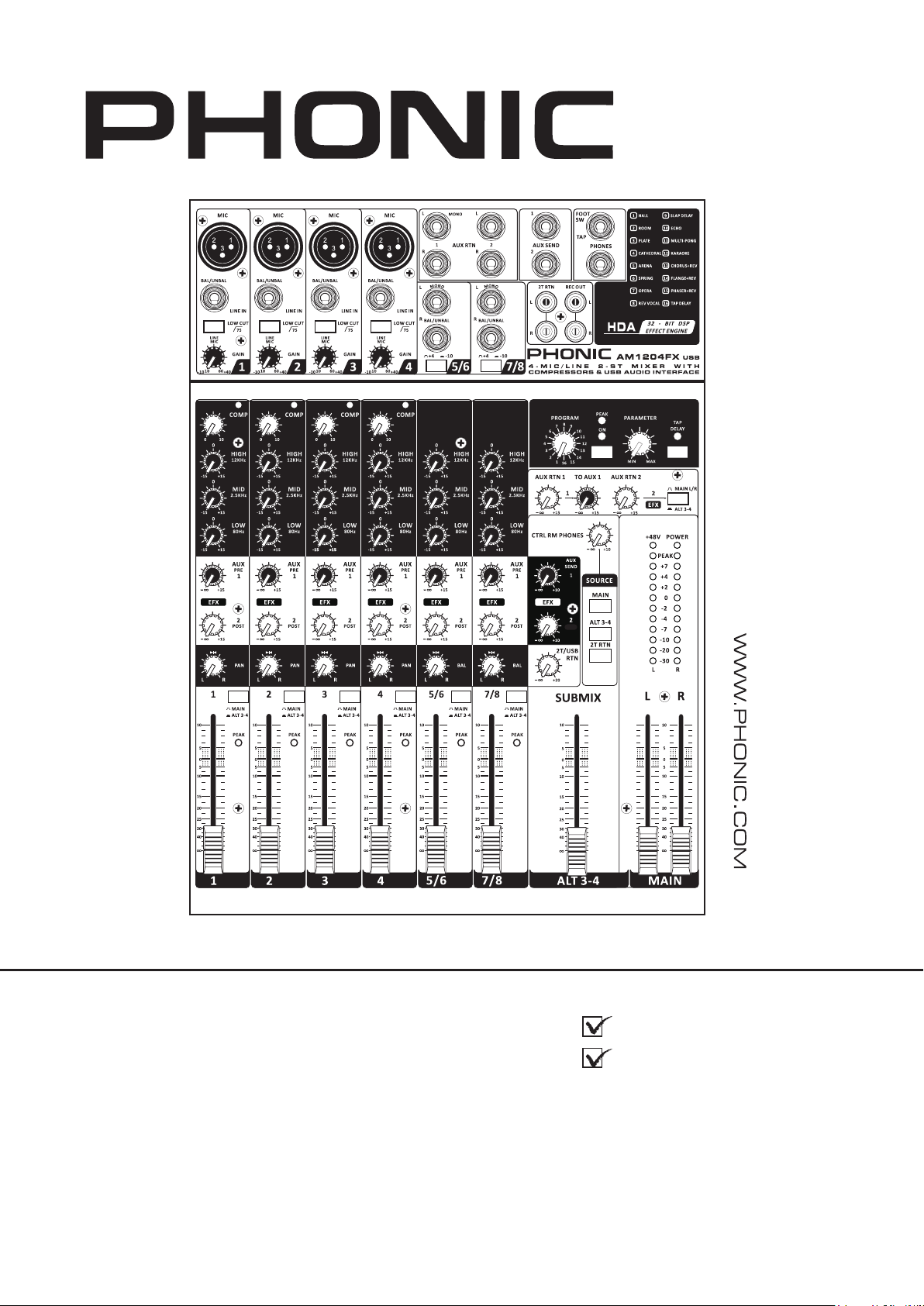
Thank you for choosing one of Phonic’s many quality compact
mixers. The AM1204, AM1204FX and AM1204FX USB compact
mixers – designed by the ingenious engineers that have created
a variety of mixers fantastic in style and performance in the past
– displays similar prociency that previous Phonic products have
shown; with more than a few renements, of course. The AM
series features full gain ranges, amazingly low distortion levels,
and incredibly wide dynamic ranges, just showing the dominance
these small machines will have in the pro audio industry.
AM1204, AM1204FX and AM1204FX USB all feature four of
Phonic’s quality low-noise preampliers accepting microphone
signals, as well as number of line-level ¼” phone jack inputs
across four mono and two stereo channels. The AM1204FX
and AM1204FX USB are both adorned with studio-quality 32-bit
digital effect processors that feature 16 unique effects, each of
which has its own user-adjustable parameter. Featured solely on
the AM1204FX USB is a stereo USB audio interface, perfect for
sending audio directly to any modern OSX or Windows based
computer. Stereo audio can also be injected straight into your mix
via the USB interface.
We know how eager you are to get started – wanting to get the
mixer out and hook it all up is probably your number one priority
right now – but before you do, we strongly urge you to take a look
through this manual. Inside, you will nd important facts and gures
on the set up, use and applications of your brand new mixer. If
you do happen to be one of the many people who atly refuse to
read user manuals, then we just urge you to at least glance at
the Instant Setup section. After glancing at or reading through the
manual (we applaud you if you do read the entire manual), please
store it in a place that is easy for you to nd, because chances are
there’s something you missed the rst time around.
FEATURES
Common Features:
4 mono mic/line channels with our famously low-noise
preampliers
2 stereo channels with +4 / -10 pad switches for greater input
versatility
AUX/EFX sends on each channel for creating monitor mixes
and incorporating external signal processors
Two stereo AUX returns for incorporating external signals
into the mix
AUX Return 1 features “to main” control for versatile EFX
monitoring
75Hz low-cut lter on mono channel for removing stage
rumble
ALT 3-4 mix for redirecting muted channels to their own
output
3-band EQ on every channel
+48V phantom power on mic channels
11 segment level meter giving visual depictions
Extremely versatile control room/phones source matrix for
maximum monitor exibility
Balanced XLR outputs
AM1204FX plus:
32-bit digital effect engine with 16 EFX, each with their own
user-adjustable parameter
AM1204FX USB plus:
2x2 USB audio interface for sending and returning stereo au-
dio to and from a computer
32-bit digital effect engine with 16 EFX, each with their own
user-adjustable parameter
Variable compressor function on mono channels, ideal for
vocals and drums
GETTING STARTED
1. Ensure all power is turned off on your mixer. To totally
ensure this, the power supply should not be connected to
the unit.
2. No input other than the one being set should have any
device plugged in. This will ensure the purest signal is used
when setting channels.
3. Set the level control of the channel you are setting to the 0
dB mark.
4. Disengaged the Mute button for the channel you wish to set.
5. Ensure the channel has a signal sent to it similar to the signal
that will be sent when in common use. For example, if the
channel is using a microphone, then you should speak or
sing at the same level the performer normally would during
a performance; if a guitar is plugged into the channel, then
the guitar should also be strummed as it normally would be
(and so on). This ensures levels are completely accurate
and avoids having to reset them later.
6. Set the gain control on the channel so that the level meter
indicates the audio level is around 0 dB.
7. This channel is now ready to be used; you can stop making
the audio signal.
8. You can repeat the same process for other channels. Or not,
it’s your call.
USB INTERFACE
System Requirements
Windows
Windows™ XP SP2, Vista™, 7 or 8
Intel™ Pentium™ 4 processor or better
512 MB RAM (1 GB recommended)
Macintosh
Apple™ Mac™ OSX 10.5 or higher
G4 processor or better
512 MB RAM (1 GB recommended)
English
AM1204 / AM1204FX / AM1204FX USB 1
Page 6

COMPUTER CONNECTION
By simply connecting the USB cable provided along with your AM1204FX USB to the device and your Personal Computer or Laptop, you
are able to send CD quality (16-bit stereo, with a 44.1 kHz sampling rate) signal to and from your mixer. By doing this, you are actually
English
turning your AM1204FX USB into a highly useful plug’n’play soundcard for your computer.
The USB sends an audio stream of the Main Left and Right (record out) signal of your mixer to the computer. You can use almost any
dedicated Digital Audio Workstation (DAW) software to record the signal from the AM1204FX USB mixer. You can also set the mixer as
your default audio device.
The USB interface also returns the audio signal from your computer back to the 2T Returns, the signal of which is controlled by the 2T /
USB Return control. If there are input signals from both the USB interface and the 2T Return, the two signals are combined and controlled
simultaneously by the 2T return control.
Windows
1. Turn on both the AM1204FX USB and your computer.
2. Connect the mixer to the computer via the provided USB cable.
3. Let Windows nd the device and install an appropriate USB sound driver.
4. Enter the Control Panel and select Sounds and Audio Devices.
5. When here, go to the Audio tab and select the “USB Audio Codec” as your default sound recording and playback device.
6. Depending whether you have Windows XP, Vista, 7 or 8, this may differ slightly, but the settings can always be found within the
Control Panel’s audio menu.
7. If you don’t want to use the AM1204FX USB as your computer’s default audio device, you can simply enter your DAW or other audio
software and select “USB Audio Codec” as your default device. This will allow the interface to be used within the software only.
Mac
1. Turn both the AM1204FX USB and the computer on.
2. Connect the AM mixer to the computer via the provided USB cable.
3. Enter the AUDIO MIDI SETUP menu.
4. Select the “USB Audio Codec” as your input and output device.
5. The AM1204FX USB is now your default audio device.
6. Alternatively, enter your DAW software (or other relevant audio program) and select the “USB Audio Codec” in the device preferences.
7. Be sure to set your minimum buffer settings to 64 samples as to avoid clicks and pops.
AM1204 / AM1204FX / AM1204FX USB2
Page 7
MAKING CONNECTIONS
Inputs and Outputs
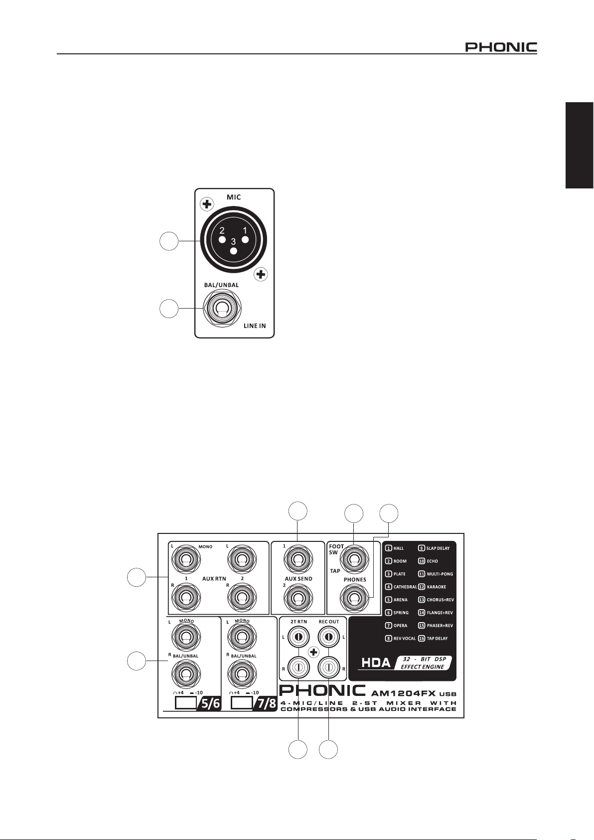
1. Inputs and Outputs
These jacks accept typical 3-pin XLR inputs for balanced and
unbalanced signals. They can be used in conjunction with
microphones – such as professional condenser, dynamic or
ribbon microphones - with standard XLR male connectors, and
feature low noise preampliers, serving for crystal clear sound
replication. The AM1204, AM1204FX and AM1204FX USB
mixers feature four standard XLR microphone inputs for your
convenience.
NB. When these inputs
are used with condenser
microphones, the Phantom
Power should be activated.
However, when Phantom
Power button is engaged,
single ended (unbalanced)
microphones and
instruments should not be
used on the Mic inputs.
2. Line Inputs
This input accepts typical
1/4” TRS or TS inputs, for
balanced or unbalanced
signals. There are various
numbers of these inputs
depending which mixer you are using. They can be used in
conjunction with various line level devices, such as keyboards,
drum machines, electric guitars, and a variety of other electric
instruments.
3. Stereo Channels
AM1204, AM1204FX and AM1204FX USB mixers feature two
stereo channels thrown in for maximum exibility. Each of these
stereo channels features two 1/4” TRS phone jacks, for the
addition of various line level input devices, such as electronic
keyboards, guitars and external signal processors or mixers.
These stereo channels can also be used as mono channels,
where the signal from any 1/4” phone jack plugged into the Left
stereo input will cause the signal to be duplicated to the Right
input due to the miracle of jack normalizing. This does not work
in reverse, however.
1
2
4. AUX Returns
These 1/4” TS inputs are for the return of audio to the AM1204,
AM1204FX and AM1204FX USB mixers, processed by an
external signal processor. If really needed, they can also be used
as additional stereo input channels. The feed from these inputs
can be adjusted using the AUX Return controls on the face of the
mixer. When connecting a monaural device to the AUX Return 1
and 2 inputs, simply plug a 1/4” phone jack into the left (mono)
input, and the signal will appear in the right as well.
NB. When any device is plugged into AUX Return 2, the mixer’s
internal digital effect engine is then disabled.
5. AUX Sends
These 1/4” TS outputs may be used to connect to an external
digital effect processor, or even to an amplier and speakers
(depending on your desired settings), to the mixer. The signal
sent from the AUX outputs are fed from the master AUX send
controls which themselves get their signals from the individual
AUX controls on input channels.
6. Footswitch Jack
This port is for the addition of a non-latching type footswitch. This
can be used when the tap delay effect is chosen to adjust the
tap delay parameter. By tapping the footswitch twice, the DFX
processor will calculate the time between the two taps and use
this as the tap delay time. When tapped multiple times, only the
last two taps will be considered.
7. Phones Connector
This stereo output port is suited for use with headphones,
allowing monitoring of the mix. The audio level of this output is
controlled using the Phones / Submix control.
8. Record Out
These outputs will accommodate RCA cables, able to be fed
to a variety of recording devices such as digital recorders, tape
recorders, and even laptop computers.
9. 2T Return
These RCA stereo inputs are used to connect the mixer with
external devices, such as tape and CD players, or even Laptop
computers, receiving a signal from another source and feeding it
to the Main L-R mixing bus.
English
5
6
7
4
3
89
AM1204 / AM1204FX / AM1204FX USB 3
Page 8
Rear Panel
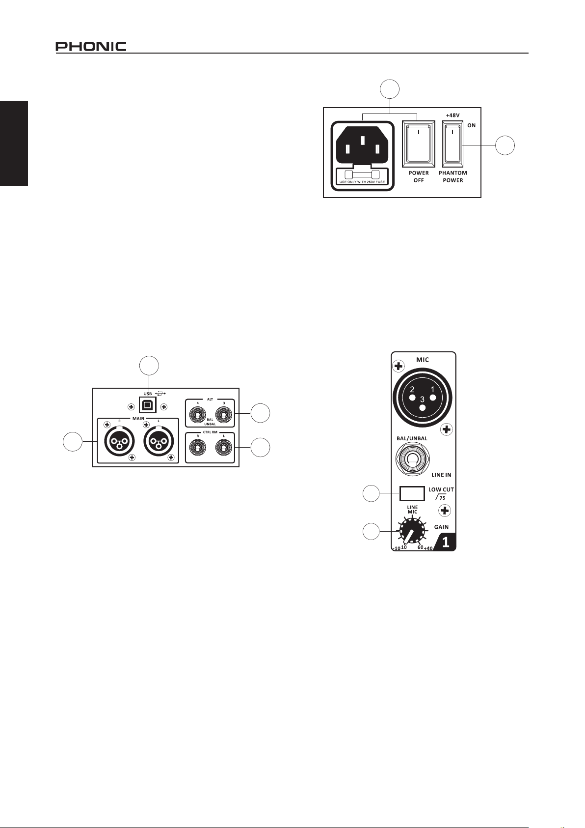
10. Main L and R Outputs
These two ports will output the nal stereo balanced line level
English
signal sent from the main mixing bus. The primary purpose of
these jacks is to send the main output to external devices, which
may include power ampliers (and in-turn, a pair of speakers),
other mixers, as well as a wide range of other possible signal
processors (Equalizers, Crossovers, etcetera).
11. Control Room Outputs
These two 1/4” Phone Jack outputs feed the signal altered by
the Control Room/Phones level control on the face of the mixer.
This output has extensive use, as it can be used to feed the
signal from the mixer to an active monitor, for the monitoring of
the audio signal from within a booth, among other possible uses.
12. ALT 3-4 Output
These unbalanced outputs are fed from the ALT 3-4 mix and
can be used in conjunction with a large array of input devices,
including signal processors, recording devices, monitor mixers,
and so on. The ALT 3-4 mix is created by muting signals on
channels 1 through 8. If no channels are muted, these outputs
will send the main mix.
13. USB Connector (AM1204FX USB Only)
This USB connector can be used to connect the AM1204FX USB
to any modern Windows or Mac-based computer. Doing so will
allow users to get a stereo signal both to and from the computer.
14
15
Channel Controls
16. Low Cut Filter (75 Hz)
This button, located on channels 1 through to 4, will activate a
low-cut / high-pass lter that reduces all frequencies below 75
Hz at 18 dB per octave, helping to remove any unwanted ground
noise or stage rumble.
17. Gain Control
These controls, found on each input channel, allow users to
adjust the sensitivity of the input signal for the Line/Microphone
input. The gain should be adjusted to a level that allows the
maximum use of the audio, while still maintaining the quality of
the feed. This can be accomplished by adjusting it to a level that
will allow the peak indicator occasionally illuminate. All 4 mono
channels feature this control.
13
11
10
CONTROLS AND SETTINGS
Back Panel
14. Power Switch and AC Connector
The power switch, located on the rear of the mixer, is used to
activate the mixer. But there’s no point in activating the mixer
if there’s no power, therefore an AC power connector has been
included to ensure your mixer gets the power it needs. Please
use the power cable that is included with this mixer only.
15. Phantom Power Switch
When this switch is in the on position, it activates +48V of
phantom power for all microphone inputs, allowing condenser
microphones (well, the ones that don’t use batteries) to be
used on these channels. Activating phantom power will be
accompanied by an illuminated LED above the left channel level
meter. Before turning Phantom Power on, turn all level controls
to a minimum to avoid the possibility of a ghastly popping sound
coming from the speakers.
NB. Phantom Power should be used in conjunction with balanced
microphones. When Phantom Power is engaged, single ended
(unbalanced) microphones and instruments should not be used
on the Mic inputs. Phantom Power will not cause damage to most
dynamic microphones, however if unsure, the microphone’s user
manual should be consulted.
12
16
17
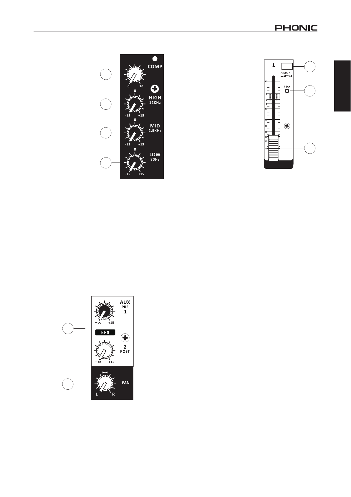
18. Compressor Control and Indicator (AM1204FX USB Only)
This controls the onboard compressor function on mono channels.
Turning this control up towards the 12 o’clock position will adjust
the threshold and ratio of the compressor at varying degrees.
Once you reach the 12 o’clock position, the control will then
adjust the compression settings along with an onboard expander
(or, in other words, a “compander”). The LED that accompanies
this control will light up when the compressor is triggered. This
control and indicator can only be found on mono channels of the
AM1204FX USB.
19. High Frequency Control
This control is used to give a shelving boost or cut of ±15 dB to
high frequency (12 kHz) sounds. This will adjust the amount of
treble included in the audio of the channel, adding strength and
crispness to sounds such as guitars, cymbals, and synthesizers.
AM1204 / AM1204FX / AM1204FX USB4
Page 9
20. Middle Frequency Control
This control is used to provide a peaking style of boost and
cut to the level of middle
frequency (2.5 kHz) sounds at
a range of ±15 dB. Changing
middle frequencies of an audio
feed can be rather difcult
when used in a professional
audio mix, as it is usually
more desirable to cut middle
frequency sounds rather
than boost them, thereby
soothing overly harsh vocal
and instrument sounds in the
audio.
21. Low Frequency Control
This control is used to give a
shelving boost or cut of ±15
dB to low frequency (80 Hz)
sounds. This will adjust the
amount of bass included in the
audio of the channel, and bring
more warmth and punch to
drums and bass guitars.
22. AUX / EFX Controls
The AUX 1 and 2 controls allow the user to send the corresponding
signal to the AUX 1 and 2 mixes, the nal levels of which are
controlled by the AUX Send controls on the main mixing panel.
These signals are then sent to the corresponding AUX Send
Outputs for use with ampliers and studio or stage monitors, or
simply in conjunction with external processors. AUX 1 features a
pre-fader, pre-EQ signal, while AUX 2’s signal is post-fader, postEQ. The AUX 2 control doubles EFX control on the AM1204FX
and AM1204FX USB, adjusting the signal that is sent to the builtin Digital Effects Processor.
18
19
20
21
24. Mute Button and Indicator
This button turns a mute on the corresponding channel on and
off, stopping all audio from the channel input to the Main mix.
The corresponding indicator will
be illuminated when the mute is
activated. When a channel is muted,
this audio – which would normally be
wasted – is redirected to the ALT 3-4
mix.
25. Peak Indicator
This LED indicator will illuminate
when the device hits high peaks, 6
dB before overload occurs. It is best
to adjust the gain of the channel so
that the PEAK indicator lights up
on intervals only, if at all. This will
ensure a greater dynamic range of
audio.
26. Level Control
This 60mm fader will alter the
signal level that is sent from the
corresponding channel to the main mix.
27. +4 / -10 Switch
This button, located on both stereo channels, is used adjust the
input sensitivity of the corresponding channels. This will adapt
the channel to external devices that use different operating
levels. If the input source is -10 dBV (consumer audio level), it is
best to engage the switch, allowing the signal to be heard. The
+4 dBu level is suitable for professional audio signals, which are
considerably higher than the consumer level. However, if you are
unsure of the source’s operating level, we suggest leaving the
switch disengaged until you test the source’s signal. You can then
engage if necessary (if the level of the input signal is obviously
too low).
24
25
26
English
23. Pan / Balance Control
This alternates the degree or level of audio that the left and right
side of the main mix should receive. On mono channels, this
control will adjust the level that the left and right should receive
(pan), whereas on a stereo channel, adjusting the BAL control
will increase the left or right audio signals accordingly (balance).
22
23
AM1204 / AM1204FX / AM1204FX USB 5
Page 10
Digital Effect Section (AM1204FX and AM1204FX
USB)
English
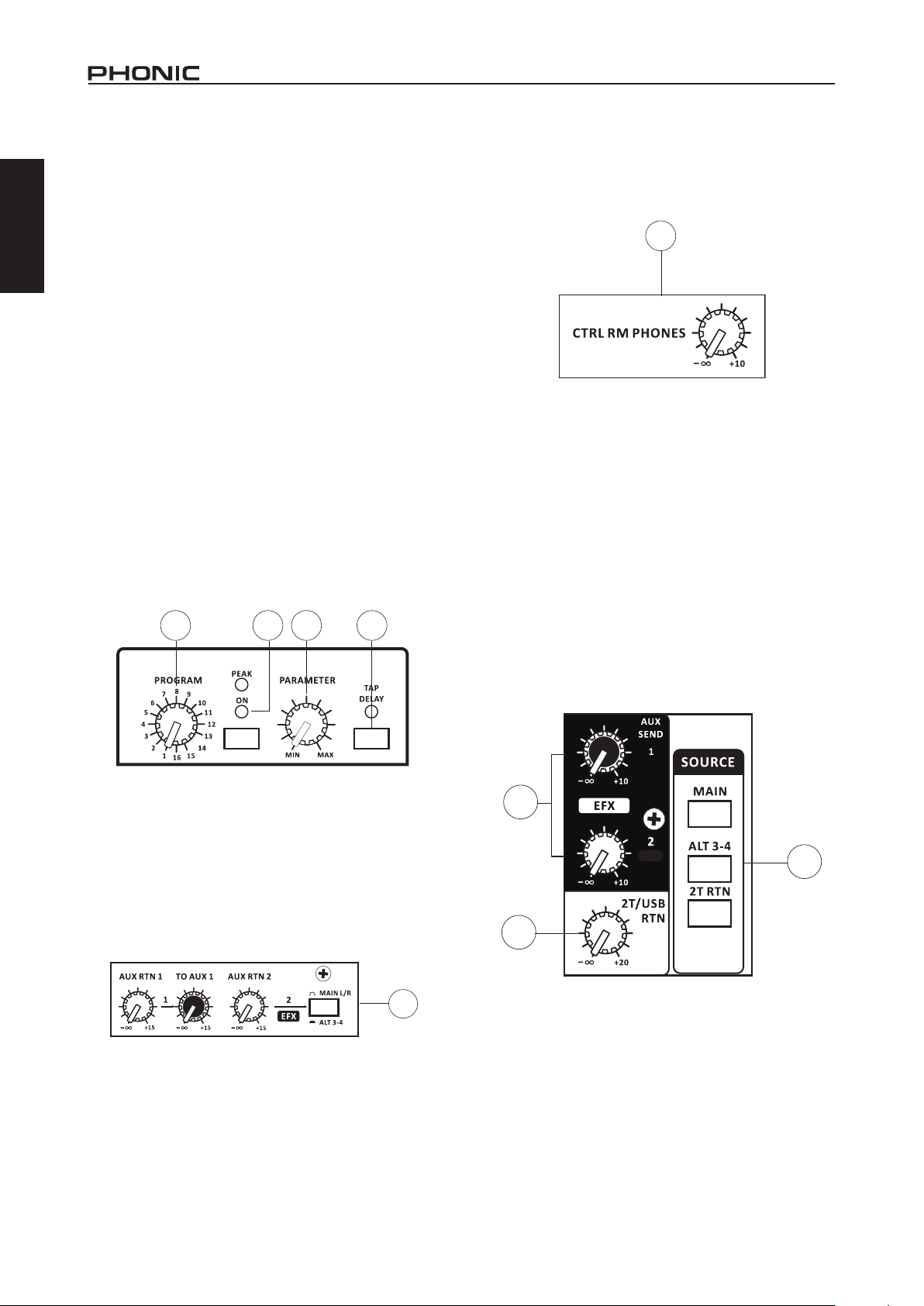
28. Program Control
This control will allow users to select one of the 16 built-in digital
effects of the AM mixer. The effect names that correspond with
the numbers can be found on the top of the mixer’s face, or in the
digital effect table.
29. Effects On Button and Indicators
Pushing this button will turn the built-in effect processor on and
off. When the effect processor is activated, the corresponding
LED will light up to indicate so. The uppermost LED is a
Peak indicator. This will light up when the EFX signal reaches
excessive peaks and should be lowered slightly. Please note that
unlike many other buttons on the AM mixer, the EFX ON button
will not latch down.
33. Ctrl Room / Phones Control
This control is used to adjust the audio level of the Control
Room feed, which is sent to both the Control Room outputs
(for monitoring, acting as side ll or other purposes) and
Phones outputs (to be used in conjunction with headphones for
monitoring).
33
30. Parameter Control
Turning this control will adjust the one main parameter of the
selected effect. Each effect’s adjustable parameter can be found
within the digital effect table.
31. Tap Delay Button and Indicator
This button can be used when the tap delay effect is selected
using the Program Control. The tap delay time can be selected
by pressing this button twice. The time between the two presses
will be calculated and used as the delay time. When the button
is pressed repeatedly, the time between the nal two presses will
be used as the delay time. The LED that accompanies the button
will ash at the selected intervals.
28 29 30 31
32. AUX Return Controls
These controls adjust the signal level of audio fed through the
stereo AUX Return inputs to the main mix. The “To AUX 1” control
found on the AUX Return 2 control adjusts the post-fader level
of the signal from the AUX Return to the AUX 1 Send mix. The
button that accompanies the AUX 2 Return control allows users
to determine whether the signal will be sent to the main stereo
mix or the ALT 3-4 mix. When nothing is connected to the AUX 2
Return Input, the AUX 2 Return Control will be used to control the
signal from the built-in effects processor (on the AM1204FX and
AM1204FX USB only).
34. Control Room Source Buttons
These buttons allow users to select the source signals for the
Control Rooms / Phones mix. Users are able to select from the
Main mix, ALT 3-4 mix or the 2T Return mix. When no source is
selected, the main mix alone will be sent to the control room and
headphone outputs.
35. AUX Send Controls
These controls adjust the nal level of their corresponding AUX
mixes (as taken from the AUX controls on each channel strip).
This audio is then sent to the AUX 1 and 2 Send outputs found on
the top of the mixer face.
36. 2T / USB Return
This rotary control adjusts the incoming level from the RCA 2T
input connectors as sent to the main mix (and Control Room/
Phones, if selected in the Control Room Source section). Unique
to the AM1204FX USB, this control is also used as the incoming
USB level. All incoming signals through the stereo USB audio
interface will be controlled by this control.
35
34
36
32
AM1204 / AM1204FX / AM1204FX USB6
Page 11

37. ALT 3-4 Fader
This fader is the nal level control used to adjust the ALT 3-4 mix.
This mix is created by muting input channels. Instead of simply
losing the audio from these channels, it’s redirected to the ALT
3-4 mix. In the case that no input channels are muted, the ALT
3-4 mix will consist of the main mix.
39. Level Meter
The AM’s stereo 11-segment level meter gives an accurate
indication of when audio levels of the MAIN L/R output reach
certain levels. It is suggested for the maximum use of audio to
set the various levels controls to a level slightly below that which
would cause the Peak LED to light up. This will help you get the
most out of your audio without causing any distortion.
40. Phantom Power Indicator
This LED indicator will illuminate when the AM mixer’s phantom
power circuit is turned on.
41. Power Indicator
This LED indicator will light up when the AM mixer is turned on.
English
37
38. Main Fader
This 60mm fader is nal level control for the main left and right
audio feed, sent to the Main Left and Right outputs.
38
40 41
39
AM1204 / AM1204FX / AM1204FX USB 7
Page 12

SPECIFICATIONS
English
Inputs
Total Channels 8 8 10
Balanced Mono Mic / Line
Channel
Balanced Stereo Line Channel 2 2 2
AUX Return 2 stereo 2 stereo 2 stereo
2T Input Stereo RCA Stereo RCA Stereo RCA
Outputs
Main L/R Stereo Bal. XLR x 2 Bal. XLR x 2 Bal. XLR x 2
ALT 3-4 1 1 1
Rec Out Stereo RCA Stereo RCA Stereo RCA
CTRL RM L/R 2 x 1/4” TS 2 x 1/4” TS 2 x 1/4” TS
Phones 1 1 1
EFX Send 6 6 6
Compressors - - 4
AUX Send (Pre) 1 1 1
EFX Send (Post) 1 1 1
Pan/Balance Control Yes Yes Yes
Volume Controls 60mm fader 60mm fader 60mm fader
EFX Send (Post) 1 1 1
Master Section
Phones Level Control Yes Yes Ye s
Main L/R Level Control 60 mm fader 60 mm fader 60 mm fader
Level Meter 11-segment 11-segment 11-segment
Phantom Power Supply +48V DC +48V DC +48V DC
Frequency Response (Mic input to any output)
20Hz ~ 60KHz +0/-1 dB +0/-1 dB +0/-1 dB
20Hz ~ 100KHz +0/-3 dB +0/-3 dB +0/-3 dB
Crosstalk (1KHz @ 0dBu, 20Hz to 20KHz bandwidth, channel in to main L/R outputs)
Channel fader down, other
channels at unity
Noise (20Hz~20KHz; measured at main output, Channels 1-4 unit gain; EQ at; all channels on main mix;
channels 1/3 as far left as possible, channels 2/4 as far right as possible. Reference=+6dBu)
Master @ unity, channel fader
down
Master @ unity, channel fader
@ unity
S/N ratio, ref to +4 >90 dB >90 dB >90 dB
Microphone Preamp E.I.N.
(150 ohms terminated, max
gain)
AM1204 AM1204FX AM1204FX USB
4 4 4
<-90 dB <-90 dB <-90 dB
-86.5 dBu -86.5 dBu -86.5 dBu
-84 dBu -84 dBu -84 dBu
<-129.5 dBm <-129.5 dBm <-129.5 dBm
AM1204 / AM1204FX / AM1204FX USB8
Page 13

THD (Any output, 1KHz @
+14dBu, 20Hz to 20KHz,
channel inputs)
CMRR (1 KHz @ -60dBu,
Gain at maximum)
Maximum Level
Mic Preamp Input +10dBu +10dBu +10dBu
All Other Input +22dBu +22dBu +22dBu
Balanced Output +28dBu +28dBu +28dBu
Impedance
Mic Preamp Input 2 K ohms 2 K ohms 2 K ohms
All Other Input (except insert) 10 K ohms 10 K ohms 10 K ohms
RCA 2T Output 1.1 K ohms 1.1 K ohms 1.1 K ohms
Equalization 3-band, +/-15dB 3-band, +/-15dB 3-band, +/-15dB
Low EQ 80Hz 80Hz 80Hz
Mid EQ 2.5 kHz 2.5 kHz 2.5 kHz
Hi EQ 12 kHz 12 kHz 12 kHz
Low Cut Filter 75 Hz (-18 dB/oct) 75 Hz (-18 dB/oct) 75 Hz (-18 dB/oct)
USB Audio - - Stereo In/Out
Connector Type - - USB Type B
Bitrate - - 16-bit
Sampling Rate - - 48 kHz
Digital Effect Processor -
Footswitch - Yes Yes
Power Requirements 100-240 VAC, 50/60 Hz 100-240 VAC, 50/60 Hz 100-240 VAC, 50/60 Hz
Weight 4.0 kg (8.8 lbs) 4.0 kg (8.8 lbs) 4.0 kg (8.8 lbs)
Dimensions (WxHxD)
(9.65” x 4.11” x 13.39”)
<0.005% <0.005% <0.005%
80dB 80dB 80dB
245 x 104.5 x 340 mm
16 Programs with Tap
Delay and Parameter
Control
245 x 104.5 x 340 mm
(9.65” x 4.11” x 13.39”)
16 Programs with Tap
245 x 104.5 x 340 mm
(9.65” x 4.11” x 13.39”)
Delay and Parameter
Control
English
AM1204 / AM1204FX / AM1204FX USB 9
Page 14

English
SERVICE AND REPAIR
For replacement parts, service and repairs please contact the Phonic distributor in your
country. Phonic does not release service manuals to consumers, and advice users to not
attempt any self repairs, as doing so voids all warranties. You can locate a dealer near you at
http://www.phonic.com/where/.
WARRANTY INFORMATION
Phonic stands behind every product we make with a no-hassles warranty. Warranty coverage
may be extended, depending on your region. Phonic Corporation warrants this product for a
minimum of one year from the original date of purchase against defects in material and
workmanship under use as instructed by the user’s manual. Phonic, at its option, shall repair
or replace the defective unit covered by this warranty. Please retain the dated sales receipt as
evidence of the date of purchase. You will need it for any warranty service. No returns or repairs
will be accepted without a proper RMA number (return merchandise authorization). In order to
keep this warranty in effect, the product must have been handled and used as prescribed in the
instructions accompanying this warranty. Any tampering of the product or attempts of self repair
voids all warranty. This warranty does not cover any damage due to accident, misuse, abuse,
or negligence. This warranty is valid only if the product was purchased new from an authorized
Phonic dealer/distributor. For complete warranty policy information, please visit
http://www.phonic.com/warranty/.
CUSTOMER SERVICE AND TECHNICAL SUPPORT
We encourage you to visit our online help at http://www.phonic.com/support/. There you can find
answers to frequently asked questions, tech tips, driver downloads, returns instruction and other
helpful information. We make every effort to answer your questions within one business day.
support@phonic.com
http://www.phonic.com
AM1204 / AM1204FX / AM1204FX USB10
Page 15

Manual del Usuario
CONTENIDO
INTRODUCCIÓN.....................................................................1
CARACTERÍSTICAS...................................................1
PRIMEROS PASOS...............................................................1
USB INTERFACE.........................................................1
CONEXIÓN CON EL ORDENADOR......................................2
CONEXIONES............................................................3
CONTROLES Y AJUSTES..............................................4
ESPECIFICACIONES..............................................................8
APÉNDICE
TABLA DE EFECTO DIGITAL..................................................1
APLICACIÓN...........................................................................2
English Español
DIMENSIONES........................................................................3
Phonic se reserva el derecho de mejorar o alterar cualquier información
provista dentro de este documento sin previo aviso.
Page 16

English Español
Page 17

INTRODUCCIÓN
Gracias por elegir uno de los mezcladores compactos de alta
calidad de Phonic. Los mezcladores compactos AM1204,
AM1204FX y USB AM1204FX han sido - diseñados por los mas
grandes ingenieros, que han creado una variedad de mezcladoras
fantásticas en estilo y rendimiento nunca igualado en el pasado. La
serie AM presenta toda una gama de mejora niveles de distorsión
sorprendentemente bajos y rangos dinámicos muy amplios.. Con
estas pequeñas máquinas conseguirá Vd. el dominio de la industria
del audio profesional .
Los AM1204, AM1204FX y AM1204FX USB disponen de
preamplicadores Phonic de calidad a bajo ruido que aceptan
señales de micrófono; así como conectores telefónicos a nivel
linear de 6.35mm a través de cuatro entradas mono y dos canales
estéreo. El AM1204FX y USB AM1204FX poseen procesadores
de efectos digitales de calidad de estudio a 32-bits que cuentan
con 16 efectos únicos, cada uno de los cuales tiene su propio
parámetro ajustable por el usuario. Destacados únicamente en el
AM1204FX USB es un interfaz de audio USB estéreo, ideal para
enviar audio directamente a cualquier ordenador moderno OSX o
Windows. Audio estéreo también se puede inyectar directamente
en la mezcla a través de la interfaz USB.
Sabemos lo deseosos que está Vd. de empezar - queriendo
sacar la mezcladora y conectarla ; todo esto es probablemente
su principal prioridad en estos momentos - pero antes de hacerlo,
le insto a que dé un vistazo a este manual. Dentro, usted
encontrará consejos importantes y cifras sobre la conguración,
uso y aplicaciones de su nueva mezcladora. Si llegara a ser una
de las muchas personas que se niegan rotundamente a leer los
manuales, entonces le pedimos que lea solamente las primeras
páginas. Después de hojear o leer el manual (le felicitamos si lee
todo el manual), por favor guárdelo en un lugar que sea fácil de
encontrar, porque lo más probable es que haya algo que Vd. se
perdió la primera vez.
CARACTERÍSTICAS
Características comunes:
4 mono canales mic / línea con nuestras famosas preampli-
cadores de bajo ruido
2 canales estéreo con conmutadores de pad +4 / -10 para
una versatilidad mayor
Envía en cada canal AUX / EFX para crear mezclas de moni-
torización y la incorporación de los procesadores de señal
externos
Dos retornos AUX estéreo para incorporar las señales exter-
nas en la mezcla
AUX RETORNO AUX a ¨Main¨ para control versátil EFX
Filtro de corte bajo75Hz en los canales mono para eliminar
vibraciones del escenario
Mezcla ALT 3-4 para redireccionar los canales apagados
para su propia producción
EQ de 3-bandas en cada canal
+48 V de alimentación fantasma en canales de micrófono
11 medidor de nivel de segmento dando representaciones
visuales
Control Extremadamente versátil sala / matriz de teléfonos
fuente para la exibilidad máxima del monitor
Salidas balanceadas XLR
AM1204FX plus:
Motor de efectos digitales con 16 EFX de 32-bit, cada uno
con su propio parámetro ajustable por el usuario
AM1204FX USB plus:
Interfaz de audio USB 2x2 para el envío y retorno de audio
estéreo hacia y desde una computadora
motor de efectos digitales con 16 EFX de 32-bit, cada uno
con su propio parámetro ajustable por el usuario
Función de compresor variable en los canales mono, ideal
para voces y batidos de tambores o batería
PRIMEROS PASOS
1. Asegúrese de que toda la alimentación está apagada en
su mesa de mezclas. Para garantizar totalmente esto;
desconecte la fuente de alimentación.
2. Todos los faders y controles de nivel debe jarse en el nivel
más bajo y todos los canales apagados para asegurar que
ningún sonido es enviado accidentalmente a las salidas
cuando el dispositivo está encendido. Todos los niveles
pueden ser alterados a grados aceptables después de que
el dispositivo está encendido utilizando las instrucciones de
conguración de canal.
3. Conecte todos los equipos necesarios en diferentes
salidas del dispositivo. Esto puede incluir amplicadores
y altavoces, monitores, procesadores de señal y / o
dispositivos de grabación.
4. Enchufe el cable de alimentación suministrado a la entrada
en la parte posterior del dispositivo y luego en una toma de
corriente de un voltaje adecuado.
5. Gire el interruptor de encendido y siga las instrucciones de
conguración de canal para obtener el máximo rendimiento
de su equipo.
6. Encienda los amplicadores o altavoces conectados
después de encender la mezcladora AM. Al apagar el
sistema, los amplicadores o altavoces con alimentación
deben ser lo primero, seguido por el mezclador.
7. Este canal está ahora listo para ser utilizado, se puede
dejan de producir las señal de audio.
8. Se puede repetir el mismo proceso para otros canales. O
no, es su llamada.
USB INTERFACE
System Requirements
Windows
Windows™ XP SP2, Vista™, 7 or 8
Intel™ Pentium™ 4 processor or better
512 MB RAM (1 GB recommended)
Macintosh
Apple™ Mac™ OSX 10.5 or higher
G4 processor or better
512 MB RAM (1 GB recommended)
English Español
AM1204 / AM1204FX / AM1204FX USB
1
Page 18

CONEXIÓN CON EL ORDENADOR
Sólo tiene que conectar el cable USB suministrado junto con su AM1204FX USB al ordenador/ ordenador portátil, usted puede enviar señal
de calidad CD (16-bit estéreo, con una tasa de muestreo de 44,1 kHz) hacia y desde su mesa de mezclas. De esta manera, en realidad
English Español
está convirtiendo su AM1204FX USB en una tarjeta de sonido plug’n’play muy útil para su equipo.
El USB envía un ujo de audio del izquierdo y derecho principal (main left y main right ) de la mesa de mezclas al ordenador. Usted
puede utilizar casi cualquier estación de software dedicada al audio digital (DAW) para grabar la señal de la mezcladora AM1204FX USB.
También puede congurar el mezclador como dispositivo de audio predeterminado.
La interfaz USB también devuelve la señal de audio de su equipo a los retornos 2T, la señal que está controlada por el 2T / control de
retorno de USB. Si hay señales de entrada de interfaz USB y del Retorno 2T, las dos señales se combinan y se controlan simultáneamente
por el control de retorno 2T.
Window
1. Encienda el AM1204FX USB y su ordenador.
2. Conecte el mezclador al ordenador mediante el cable USB suministrado.
3. Dejar que Windows encuentra el dispositivo e instalar un controlador USB adecuado.
4. Introduzca el Panel de control y seleccione Sonidos/Sounds y dispositivos de audio.
5. Cuando llegue aquí, vaya a la pestaña Audio y seleccione “USB Audio Codec”, como grabación de sonido predeterminado y el
dispositivo de reproducción.
6. Dependiendo de si usted tiene Windows XP, Vista, 7 u 8, esto puede variar ligeramente, pero los ajustes siempre se pueden
encontrar dentro del menú del panel de control.
7. Si no desea utilizar el dispositivo USB AM1204FX como predeterminada del equipo de audio, sólo tiene que introducir su DAW
o software de audio y seleccione “USB Audio Codec” como dispositivo predeterminado. Esto permitirá que la interfaz pueda ser
utilizada dentro del software solamente.
Mac
1. Encienda el USB AM1204FX y el ordenador encendido.
2. Conecte el mezclador AM al ordenador a través del cable USB suministrado.
3. Entre en el menú Conguración de Audio MIDI.
4. Seleccione la opción “USB Audio Codec” como dispositivos de entrada y salida.
5. El USB AM1204FX es ahora el dispositivo de audio predeterminado.
6. También puede introducir su software DAW (u otro programa de audio correspondiente) y seleccione la opción “USB Audio Codec”
en las preferencias del dispositivo.
7. Asegúrese de ajustar bien la conguración del búfer a 64 de muestras, para evitar los clics y pops.
2
AM1204 / AM1204FX / AM1204FX USB
Page 19

CONEXIONES
Entradas Y Salidas
1. Conectores Jacks Xlr Para Micrófono
Estos jacks aceptan entradas típicas XLR de 3-pin para
señales balanceadas y no balanceadas. Pueden ser utilizados
junto con micrófonos - tales como micrófonos de condensador
profesionales, micrófonos dinámicos o de cinta - con conectores
estándar XLR machos y preamplicadores de bajo ruido,
sirven para reproducción de sonido cristalino. Los mezcladores
AM1204, AM1204FX y AM1204FX USB disponen de cuatro
entradas mic XLR estándar
para su conveniencia.
NB. Cuando estas entradas
se utilizan con micrófonos
de condensador, la Fuente
Fantasma debería estar
activada. Sin embargo,
cuando el botón de
alimentación fantasma está
activado, los instrumentos
de micrófonos no deben ser
utilizados en las entradas
de micrófono.
2. Entradas De Línea
Esta entrada acepta
conexiones típicas TRS o
TS de 6.35mm, para señales
balanceadas y no balanceadas. Hay varios números de estas
entradas que dependen de la mezcladora que está utilizando.
Se pueden utilizar en combinación con diversos dispositivos de
nivel de línea, como teclados, guitarras eléctricas, y una diversos
otros instrumentos eléctricos.
3. Canales Estéreo
Mezcladores AM1204, AM1204FX y AM1204FX USB disponen
de dos canales estéreo ofreciendo una máxima exibilidad.
Cada uno de estos canales estéreo cuenta con dos conectores
TRS jacks de 6.35mm, para la adición de varios dispositivos
de entrada de línea de nivel, tales como teclados electrónicos,
guitarras y procesadores de señal externos o mezcladoras.
4. Regreso AUX
Estas 1/4 “entradas TS son para el retorno de audio a la AM1204,
AM1204FX y mezcladores AM1204FX USB, procesada por un
1
2
procesador de señal externo. Si realmente es necesario, también
se pueden utilizar como canales de entrada estéreo adicionales.
La alimentación de estas entradas puede ser ajustada utilizando
los controles de Retorno AUX en la cara de la mezcladora.
Cuando se conecta un dispositivo monoaural para el Retorno
AUX 1 y 2 entradas, basta con conectar una de 1/4 jack “a la
izquierda (mono), y la señal aparecerá en la derecha también.
NB. Cuando un dispositivo está conectado al Retorno AUX 2, el
mezclador interno del motor efecto digital se desactiva.
5. Envíos Aux
Estas salidas de TS de 1/4 “s se puede utilizar para conectar un
procesador de efecto digital externo, o incluso a un amplicador
y altavoces (dependiendo de la conguración que desee), a la
mezcladora. La señal enviada desde las salidas AUX se alimenta
desde el AUX maestro controles de envío que se obtienen las
señales de los controles AUX individuales en canales de entrada.
Estos canales estéreo también se pueden utilizar como canales
mono, donde la señal de cualquier conectador de tipo teléfono de
6.35mm conectado a la entrada estéreo izquierda hará que la
señal se duplique en la entrada derecha debido al milagro de la
normalización de jack. Sin embargo esto no funciona en sentido
inverso.
6. Pedal Jack
Este puerto es para la adición de un interruptor de pedal tipo sin
enganche. Esto puede ser usado para ajustar el parámetro de
retardo de Tap Delay. Al pulsar dos veces el pedal, el procesador
DFX calculará el tiempo entre las dos fases y utilizar esto como
el Tap Delay . Cuando tocado varias veces, sólo los dos últimos
toques serán considerados.
7. Celulares Conector
Este puerto de salida estéreo es ideal para su uso con audífonos,
permitiendo monitorear la mezcla. El nivel de audio de esta salida
se controla mediante los controles de sub-mezcla.
8. Salida De Grabación
Estas salidas acomodarán a los cables RCA, lo cual son capaces
de alimentar a una variedad de dispositivos de grabación como
grabadoras digitales, grabadoras y computadoras portátiles.
9. Retorno 2T
These RCA stereo inputs are used to connect the mixer with
external devices, such as tape and CD players, or even Laptop
computers, receiving a signal from another source and feeding it
to the Main L-R mixing bus.
English Español
4
3
AM1204 / AM1204FX / AM1204FX USB
5
6
7
89
3
Page 20

Panel Trasero
10. Salidas Main L Y R
Estos dos puertos emiten una señal estéreo balanceada con nivel
English Español
de línea enviada desde el bus de mezcla principal. El propósito
principal de estos jacks es el de enviar la salida principal a
dispositivos externos, que pueden incluir amplicadores de
potencia (y en vez, un par de altavoces), otras mezcladoras, así
como una amplia gama de otros posibles procesadores de señal
(Equalizer, Crossovers, etcétera).
11. Control De Salidas De La Sala De Envíos
Estos dos conectadores telefónicos de salidas, están
alimentados por la señal alterada proviniendo de la Sala de
control. Esta salida tiene un amplio uso, ya que se puede utilizar
para alimentar la señal desde la mezcladora a un monitor activo,
para el monitoreo de la señal de audio, entre otros posibles usos.
12. Alt 3-4 De Salida
Estas salidas no balanceadas son alimentadas desde la mezcla
ALT 3-4 y se puede utilizar en conjunción con una gran variedad
de dispositivos de entrada, incluyendo procesadores de señales,
dispositivos de grabación, mezcladores de monitor, y así
sucesivamente. La mezcla ALT 3-4 esta creado por las señales
de muting en los canales 1 a 8. Si no hay ningún canal silenciado,
estas salidas se envían la mezcla principal.
13. Conector Usb (Usb Am1204fx Solamente)
Este conector USB se puede utilizar para conectar el AM1204FX
USB a cualquier ordenador Windows o Mac moderno. Si lo hace,
permitirá a los usuarios obtener una señal estéreo desde y hacia
el ordenador.
Controles Del Canal
16. Filtro De Corte Bajo (75 Hz)
Este botón, situado en los canales 1 a 4, se activará de ltro corte
bajo / ltro paso alto que reduce todas las frecuencias por debajo
de 75 Hz a 18 dB por octava, lo que ayuda a eliminar el ruido de
fondo o vibraciones no deseado.
17. Control De Ganancia
Estos controles, que se encuentran en cada canal de entrada,
permiten a los usuarios ajustar la sensibilidad de la señal
de entrada para la entrada de línea / micrófono. La ganancia
debe ajustarse a un nivel que permite el uso máximo de audio,
mientras que todavía mantiene la calidad de la alimentación.
Esto se puede lograr mediante el ajuste a un nivel que permite
que el indicador de pico se ilumine ocasionalmente. Todos los 4
canales mono disponen de este control.
14
15
13
11
10
CONTROLES Y AJUSTES
Panel Posterior
14. Interruptor Y Conector De Alimentación De Ca
El interruptor de alimentación, situado en la parte trasera del
mezclador, se utiliza para activar el mezclador. un conector de
alimentación CA por lo tanto ha sido incluido. Por favor, utilice el
cable de alimentación que se incluye con esta mezcladora.
15. Interruptor De Alimentación Fantasma
Cuando este interruptor está en la posición de encendido,
se activa +48 V de alimentación fantasma para todas las
entradas de micrófono, micrófono de condensador permitiendo
( naturalmente los que no usan baterías) para ser utilizados
en estos canales. Activación de la alimentación fantasma será
acompañada por un LED iluminado encima del medidor de nivel
del canal izquierdo. Antes de encender la Fuente Fantasma,
coloque todos los controles en el nivel mínimo para evitar la
posibilidad de un sonido estallido proceda de los altavoces.
12
16
17
18. Compresor De Control E Indicador (Am1204fx Usb Sólo)
Controla el funcionamiento del compresor a bordo en los canales
mono. Girando este control hacia en posición de 12:00h ajustará
el umbral y ratio del compresor en diversos grados. Una vez que
llegue a la posición de las 12:00h en punto, el control ajustará los
ajustes de compresión junto con un expansor a bordo. el LED
que acompaña a este control se encenderá cuando el compresor
se activa. Este control y el indicador sólo se puede encontrar en
los canales mono del USB AM1204FX .
NB. Fuente Fantasma debería ser utilizada en conjunto con
micrófonos balanceados. Cuando la alimentación fantasma está
activada, simple terminación (desbalanceados) e instrumentos
de micrófonos no debe usarse en las entradas de micrófono.
La Fuente Fantasma no causará daños a la mayoría de los
micrófonos dinámicos, sin embargo si no está seguro, manual de
usuario del micrófono debe ser consultado.
4
19. Control De Frecuencia Alta
Este control se utiliza para dar un recorte de ± 15 dB a la
frecuencia alta (12 kHz). Esto ajustará la cantidad de agudos
incluidos en el audio del canal, agregando fortaleza y claridad a
sonidos como guitarras, címbalos y sintetizadores.
AM1204 / AM1204FX / AM1204FX USB
Page 21

20. Control De Frecuencia Media
Este control se utiliza para proveer un estilo de pico de aumento
y recorte al nivel de frecuencia
media (2,5 kHz) suena en un
rango de ± 15 dB. Cambiar las
frecuencias medias de un canal
de audio puede ser bastante
difícil cuando se utiliza en una
mezcla de audio profesional,
ya que por lo general es más
deseable cortar los sonidos de
frecuencia media en lugar de
impulsarlos, así moderando
excesivamente voz áspera y
sonidos de instrumentos en el
audio.
18
19
20
21. Control De Frecuencia
Baja
Este control se utiliza para
dar un recorte de ± 15 dB a
baja frecuencia (80 Hz). Esto
ajustara la cantidad de bajos
incluidos en el audio del canal
y ofrecerá más calidez y punch
a las baterías y guitarras bass .
22. Aux / Efx Controles
Los controles AUX 1 y 2 permiten al usuario enviar la señal
correspondiente a la AUX 1 y mezclas 2, los niveles nales de
los cuales son controlados por el AUX en el panel de mezcla
principal. Estas señales son enviadas a la correspondiente
AUX con amplicadores y monitores de estudio o escenario, o
simplemente junto con los procesadores externos. AUX 1 cuenta
con un pre-fader, pre-ecualización de la señal, mientras que la
señal AUX 2 es post-fader, post-EQ. AUX 2 Control de dobles
EFX control en la AM1204FX y USB AM1204FX, el ajuste de la
señal que se envía al procesador integrado de efectos digitales.
23. Pan / Balance De Control
Alterna el grado o nivel de audio que los lados izquierdo y
derecho de la mezcla principal debería recibir. En los canales
mono, este control ajustará el nivel izquierdo y derecho deben
recibir (pan), mientras en canal estéreo, el ajuste del control
BAL incrementará las señales de audio izquierda o derecha en
consecuencia (balance).
21
24. Botón De Silencio E Indicador
Este botón activa pone el canal correspondiente en mudo,
parando todo el audio de la entrada del canal a la mezcla principal
El indicador correspondiente
se iluminará cuando un canal
esté silenciado; el audio -.., Que
normalmente se habría perdido - se
redirigerá a la mezcla ALT 3-4.
25. Indicador De Pico
Este indicador LED se ilumina
cuando el dispositivo alcanza a
picos altos, 6dB antes de que ocurra
la sobrecarga. Lo mejor es ajustar
la ganancia del canal para que se
encienda el indicador PEAK en
intervalos de sólo, en todo caso.
Esto asegurará un mayor rango
dinámico de audio.
26. Nivel De Control
Este fader de 60mm alterará el nivel
de señal que se envía desde el
canal correspondiente a la mezcla principal.
27. Interruptor De +4 / -10
Este botón, situado en ambos canales estéreo, se usa para ajustar
la sensibilidad de entrada de los canales correspondientes.
Esto adaptará el canal a los dispositivos externos que utilizan
diferentes niveles de operación. Si la fuente de entrada es
-10 dBV (nivel de audio de consumo), es mejor enganchar el
interruptor, permitiendo que la señal sea escuchada. El nivel de
+4 dBu es adecuado para profesionales de señales de audio,
que son considerablemente más altos que el nivel de consumo.
Sin embargo, si no está seguro del nivel de funcionamiento de
la fuente, le sugerimos desactivar el interruptor hasta que se
pruebe la señal de la fuente. A continuación, puede accionar el
interruptor si es necesario (si el nivel de la señal de entrada es
obviamente demasiada baja).
24
25
26
English Español
22
23
AM1204 / AM1204FX / AM1204FX USB
5
Page 22

SECCIÓN DE EFECTOS DIGITALES (AM1204FX
Y USB AM1204FX)
28. PROGRAMA DE CONTROL
English Español
Este control permitirá a los usuarios seleccionar uno de los 16
efectos integrados digitales de la mezcladora AM. Los nombres
de efecto que se corresponden con los números se encuentran
en la parte superior de la cara de la mezcladora, o en la tabla de
efecto digital.
29. Efectos Sobre Botón E Indicador
Pulsando este botón se enciende el procesador de efectos
incorporado ,en encendido y apagado. Cuando el procesador
de efectos se active, el LED correspondiente se encenderá para
indicarlo. Tenga en cuenta que a diferencia de muchos otros
botones del mezclador AM, este botón no se desactiva hacia
abajo.
33. Control Room / Phones Control
Este control se utiliza para ajustar el nivel de audio de la sala
de control , que se envía a las salidas (para la supervisión de la
calidad de la salida nal o para otros nes) y PHONES (para ser
usado en conjunción con auriculares para la supervisión).
33
30. Parámetros De Control
Al girar este control ajustará el parámetro principal del efecto
seleccionado. Parámetro ajustable Cada efecto se puede
encontrar en la tabla de efecto digital.
31. Pulse El Botón Tap Delay E Indicador
Este botón se puede utilizar cuando el efecto tap delay se
selecciona con el control del programa. El Tap delay se puede
seleccionar pulsando este botón dos veces. El tiempo entre las
dos prensas se calculará y se utiliza como el tiempo de retardo.
Cuando el botón se pulsa varias veces, el tiempo entre los
últimos dos prensas se utiliza como el tiempo de retardo. El LED
que acompaña al botón parpadeará a intervalos seleccionados.
28 29 30 31
32. Controles De Retorno Aux
Estos controles ajustan el nivel de la señal de audio alimentada
a través de las entradas de Retorno AUX estéreo para la mezcla
principal. El “To AUX 1” de control se encuentra en el Retorno
AUX 2 control ajusta el nivel post-fader de la señal de la vuelta a
la entrada AUX AUX 1 Enviar mezcla. El botón que acompaña el
AUX 2 Retorno de control permite a los usuarios determinar si la
señal se envía a la mezcla principal estéreo o la mezcla ALT 3-4.
Cuando no hay nada conectado a la entrada de retorno AUX 2,
el AUX 2 Control de retorno se utiliza para controlar la señal del
procesador de efectos integrado (en el AM1204FX y AM1204FX
sólo USB).
34. Botones De Control De Sala Emisora (Control Room
Source
Estos botones permiten a los usuarios seleccionar las señales de
origen de las salas de control de mezcla. Los usuarios pueden
seleccionar la mezcla principal, mezcla ALT 3-4 o la mezcla de
Retorno 2T. Cuando no hay ninguna fuente seleccionada, la
mezcla principal solo se enviará a la sala de control y salidas de
auriculares.
35. Controles De Envío Aux
Estos controles ajustan el nivel nal las mezclas correspondientes
AUX (tomadas de los controles AUX en cada tira de canal). Este
audio se envía entonces a la AUX 1 y 2 salidas de envío que se
encuentran en la parte superior del mezclador.
36. RETORNO 2T / USB
Este control giratorio ajusta el nivel de entrada de los conectores
de entrada RCA 2T como enviados a la mezcla principal (y
Control Room / Phones, si se selecciona en la sección de control
). Solo en el AM1204FX USB, este control también se utiliza
como nivel de entrada USB. Todas las señales entrantes a través
de la interfaz de audio estéreo USB serán controladas por este
control.
35
34
36
32
6
AM1204 / AM1204FX / AM1204FX USB
Page 23

37. Fader Alt 3-4 (Fader/Deslizador)
Este fader controla el nivel nal para ajustar la mezcla ALT 3-4.
Esta mezcla esta creada por los canales de entrada en muting.
En lugar de simplemente perder el audio de estos canales,
es redirigido a la mezcla ALT 3-4. En el caso de que no haya
canales de entrada en silencio, la mezcla ALT 3-4 consistirá en
la mezcla principal.
37
38. Fader Principal
Este fader de 60mm controla el nivel nal para la alimentación
principal de audio izquierdo y derecho, envía a las salidas
principales izquierda y derecha.
39. Medidor De Nivel
El estéreo de AM 11-segmento del medidor de nivel le da una
indicación precisa de cuando los niveles de audio de la MAIN
L / R Salida de alcanzar ciertos niveles. Se sugiere para el uso
máximo de audio para ajustar los controles de varios niveles a
un nivel ligeramente inferior a la que haría que el LED Peak se
encienda. Esto le ayudará a obtener el máximo provecho de su
audio sin causar ninguna distorsión.
40. Indicador De Alimentación Fantasma
Este indicador LED se ilumina cuando el circuito de alimentación
fantasma del mezclador de AM está encendido.
41. Indicador De Encendido
Este indicador LED se ilumina cuando el mezclador AM está
encendido.
40 41
39
English Español
38
AM1204 / AM1204FX / AM1204FX USB
7
Page 24

ESPECIFICACIONES
English Español
Entradas
Canales Totales 8 8 10
Balanced Mono Mic / Line
Canal
Canal Balanced Stereo Line 2 2 2
Retorno Aux 2 stereo 2 stereo 2 stereo
2T Entrada Stereo RCA Stereo RCA Stereo RCA
Salidas
Main L / R Estéreo Bal. XLR x 2 Bal. XLR x 2 Bal. XLR x 2
3-4 Alt 1 1 1
Rec Out Stereo RCA Stereo RCA Stereo RCA
Ctrl Rm / L R 2 x 1/4” TS 2 x 1/4” TS 2 x 1/4” TS
Teléfonos 1 1 1
Enviar Efx 6 6 6
Compresores - - 4
Aux Send (Pre) 1 1 1
Envío De Efectos (Post) 1 1 1
Pan / Balance De Control Yes Yes Yes
Controles De Volumen 60mm fader 60mm fader 60mm fader
Envío De Efectos (Post) 1 1 1
Sección Master
Teléfonos De Control De Nivel Yes Yes Ye s
Main L / R Nivel De Control 60 mm fader 60 mm fader 60 mm fader
Medidor De Nivel 11-segment 11-segment 11-segment
Alimentación Fantasma +48V DC +48V DC +48V DC
Respuesta De Frecuencia (Entrada Mic A Cualquier Salida)
20Hz ~ 60Khz +0/-1 dB +0/-1 dB +0/-1 dB
20Hz ~ 100Khz +0/-3 dB +0/-3 dB +0/-3 dB
Diafonía (1 Khz A 0 Dbu, 20Hz A 20Khz Ancho De Banda Del Canal En To Main Salidas L / R)
Fader De Canal Abajo, Otros
Canales En Unidad
Ruido (20Hz ~ 20Khz, Medido En La Salida Principal, Canales 1-4 Ganancia De Unidad; Eq Plana,
Todos Los Canales En Mezcla Principal;. Canales 1/3 Tan A La Izquierda Como Sea Posible, Canales
2/4 Tan A La Derecha Como Sea Posible = + Referencia 6Dbu)
@ Master Unidad, Fader De
Canal Abajo
@ Master Unidad, Unidad
Fader De Canal @
S / N, Ref A +4 >90 dB >90 dB >90 dB
AM1204 AM1204FX AM1204FX USB
4 4 4
<-90 dB <-90 dB <-90 dB
-86.5 dBu -86.5 dBu -86.5 dBu
-84 dBu -84 dBu -84 dBu
8
AM1204 / AM1204FX / AM1204FX USB
Page 25

Microphone Preamp E.I.N.
(150 Ohms Terminado,
Ganancia Max)
Thd (Cualquier Salida, 1Khz
@ +14 Dbu, 20Hz A 20Khz,
Entradas De Canal)
Cmrr (1 Khz @-60Dbu,
Ganancia Al Máximo)
Nivel Máximo
Mic Preamp Entrada +10dBu +10dBu +10dBu
Todas Las Demás Entradas +22dBu +22dBu +22dBu
Salida Balanceada +28dBu +28dBu +28dBu
Impedancia
Mic Preamp Entrada 2 K ohms 2 K ohms 2 K ohms
Todas Las Demás Entradas
(Excepto Insert)
Salida Rca 2T 1.1 K ohms 1.1 K ohms 1.1 K ohms
Igualdad 3-band, +/-15dB 3-band, +/-15dB 3-band, +/-15dB
Low Eq 80Hz 80Hz 80Hz
Mid Eq 2.5 kHz 2.5 kHz 2.5 kHz
Alto Eq 12 kHz 12 kHz 12 kHz
Filtro De Corte De Graves 75 Hz (-18 dB/oct) 75 Hz (-18 dB/oct) 75 Hz (-18 dB/oct)
Usb Audio - - Stereo In/Out
Tipo De Conector - - USB Type B
Bitrate - - 16-bit
Frecuencia De Muestreo - - 48 kHz
Procesador De Efectos
Digitales
Footswitch - Yes Yes
Requisitos De Alimentación 100-240 VAC, 50/60 Hz 100-240 VAC, 50/60 Hz 100-240 VAC, 50/60 Hz
Peso 4.0 kg (8.8 lbs) 4.0 kg (8.8 lbs) 4.0 kg (8.8 lbs)
Dimensiones (Wxhxd)
<-129.5 dBm <-129.5 dBm <-129.5 dBm
<0.005% <0.005% <0.005%
80dB 80dB 80dB
10 K ohms 10 K ohms 10 K ohms
-
245 x 104.5 x 340 mm
(9.65” x 4.11” x 13.39”)
16 Programs with Tap
Delay and Parameter
Control
245 x 104.5 x 340 mm
(9.65” x 4.11” x 13.39”)
16 Programs with Tap
Delay and Parameter
245 x 104.5 x 340 mm
(9.65” x 4.11” x 13.39”)
Control
English Español
AM1204 / AM1204FX / AM1204FX USB
9
Page 26

English Español
SERVICIO Y REPARACIÓN
Para refacciones de reemplazo y reparaciones, por favor póngase en contacto con nuestro
distribuidor de Phonic en su país. Phonic no distribuye manuales de servicio directamente a los
consumidores y, avisa a los usuarios que no intenten hacer cualquier reparación por si mismo,
haciendo ésto invalidará todas las garantías del equipo. Puede encontrar un distribuidor cerca
de usted en http://www.phonic.com/where/.
INFORMACIÓN DE LA GARANTIA
Phonic respalda cada producto que hacemos con una garantía sin enredo. La cobertura de
garantía podría ser ampliada dependiendo de su región. Phonic Corporation garantiza este
producto por un mínimo de un año desde la fecha original de su compra, contra defectos en
materiales y mano de obra bajo el uso que se instruya en el manual del usuario. Phonic, a su
propia opinión, reparará o cambiará la unidad defectuosa que se encuentra dentro de esta
garantía. Por favor, guarde los recibos de venta con la fecha de compra como evidencia de la
fecha de compra. Va a necesitar este comprobante para cualquier servicio de garantía. No se
aceptarán reparaciones o devoluciones sin un número RMA apropiado (return merchandise
autorization). En orden de tener esta garantía válida, el producto deberá de haber sido
manejado y utilizado como se describe en las instrucciones que acompañan esta garantía.
Cualquier atentado hacia el producto o cualquier intento de repararlo por usted mismo,
cancelará completamente esta garantía. Esta garantía no cubre daños ocasionados por
accidentes, mal uso, abuso o negligencia. Esta garantía es válida solamente si el producto fue
comprado nuevo de un representante/distribuidor autorizado de Phonic. Para la información
completa acerca de la política de garantía, por favor visite http://www.phonic.com/warranty/.
SERVICIO AL CLIENTE Y SOPORTE TÉCNICO
Le invitamos a que visite nuestro sistema de ayuda en línea en www.phonic.com/support/. Ahí
podrá encontrar respuestas a las preguntas más frecuentes, consejos técnicos, descarga de
drivers, instrucciones de devolución de equipos y más información de mucho interés. Nosotros
haremos todo el esfuerzo para contestar sus preguntas lo antes posible.
support@phonic.com
http://www.phonic.com
10
AM1204 / AM1204FX / AM1204FX USB
Page 27

DIGITAL EFFECT TABLE TABLA DE EFECTO DIGITAL
Program Parameter Variable Range
1 Hall Reverb Time 0.3 - 10 sec
2 Room Reverb Time 0.3 - 3.2 sec
3 Plate Reverb Time 0.3 - 10 sec
4 Cathedral Reverb Time 0.3 - 10 sec
5 Arena Reverb Time 0.3 - 10 sec
6 Spring Reverb Time 0.3 - 10 sec
7 Opera Reverb Time 0.3 - 10 sec
8 Rev Vocal Reverb Time 0.3 - 10 sec
9 Slap Delay Delay Time 0 - 800 ms
10 Echo Delay Time 0 - 800 ms
11 Multi-Pong Delay Time 0 - 800 ms
12 Karaoke Delay Time & Feedback Delay Time: 160 - 260 ms; Feedback: 45-65
13 Chorus + Rev Depth 0 - 100%
14 Flange + Rev Modulation Frequency 0.05 - 4.00 Hz
15 Phaser + Rev Modulation Frequency 0.05 - 4.00 Hz
16 Tap Delay Feedback Gain 0 - 99%
Appendix Apéndice
AM1204 / AM1204FX / AM1204FX USB
1
Page 28

Appendix Apéndice
APPLICATION APLICACIÓN
AFOH SPEAKERS
CAJAS ACÚSTICAS
COMPUTADORA PORTÁTIL
AMPLIFICADOR
ACTIVE MONITORS
MONITORES ATIVOS
MICROPHONES
MICRÓFONOS
GUITAR EFFECTS
EFECTOS DE GUITARRA
DRUM MACHINE
MÁQUINA DE TAMBOR
TECLADO
CD PLAYER
REPRODUCTOR DEC
FOOTSWITCH
INTERRUPTOR DE PEDAL
AUDIOFONO
2
AM1204 / AM1204FX / AM1204FX USB
Page 29

DIMENSIONS DIMENSIONES
AM1204FX USB
235 / 9.3
Appendix Apéndice
271 / 10.7
245 / 9.6
105 / 4.1
88 / 3.5
340 / 13.8
* All measurements are shown in mm/inches.
* Todas las medidas están mostradas en mm/pulgadas.
AM1204 / AM1204FX / AM1204FX USB
3
3
Page 30

Page 31

Page 32

 Loading...