

Philips VR407/77, VR625/77, VR620/77 Service Manual
Video Cassette Recorder VR407/77, VR620/77, VR625/77
VR407/77
Contents
Chapter
1 Disassembly
2 Mechanism adjustments
3 Electrical adjustments
4 Charts and diagrams
5 Parts lists
Safety regulations require that the set be restored to its original
condition and that parts which are identical with those specified be
used.
Specification:
Video recording system: VR407/77 - 4-head helical scan system
VR620,VR625/77 - 6-head helical scan
system (2 Audio heads)
Antenna input Signal: PAL-N, NTSC
Antenna: VHF/ UHF 75Ω external antenna terminal
Video Output Channel: Channel 3 or 4 (selectable)
75Ω unbalanced
Power requirement: AC110V – 240V, 50/60Hz
Power consumption: VR407/77 - 14W
VR620/77, VR625/77 - 16W
Operating temperature: 41°F(5°C) a104°F(40°C)
Relative humidity: 10% to 80%
Weight: 3.0kg
Dimensions: VR407/77 - 360 x 94 x 251mm
VR620/77, VR625/77 - 360 x 94 x 242mm
Published by CFC2001PJVM Videq Service Department Printed in the Netherlands © Copyright reserved Subject to modification
01A40777.pm5
3103 785 20870

VR407/77, VR620/77, VR625/77
1. ACCESSORIES
306 9965 000 04494 REMOTE CONTROLLER,VR407/77
9965 000 07845 REMOTE CONTROLLER,VR620/77,
VR625/77
306A 9965 000 04496 COVER(BATTERY),VR407/77
310 9965 000 08713 INST BOOK(SP),VR407/77
9965 000 08704 INST BOOK(SP),VR620,VR625/77
2. CABINET AND CHASSIS ASSEMBLY
501 ! 9965 000 08701 FRONT PANEL ASSY,VR620/77
! 9965 000 08714 FRONT PANEL ASSY,VR625/77
! 9965 000 08715 FRONT PANEL ASSY,VR407/77
501A 9965 000 07920 CASS DOOR,VR620/77,VR625/77
9965 000 07878 CASS DOOR,VR407/77
501B 4822 492 42781 TORSION SPRING
501C 9965 000 08702 DISPLAY WINDOW,VR620/77,
VR625/77
9965 000 08716 DISPLAY WINDOW,VR407/77
501D 9965 000 08717 ORNAMENT,VR625/77
9965 000 07921 ORNAMENT,VR620/77
501E 9965 000 07922 DOOR(JACK),VR620/77,VR625/77
502 ! 9965 000 07923 TOP COVER,VR620/77,VR625/77
! 9965 000 07884 TOP COVER,VR407/77
505 9965 000 07839 DRUM SUB ASSY,VR620//77,
VR625/77
9965 000 08010 DRUM SUB ASSY,VR407/77
505E 4822 265 11367 CONTACT
505F 4822 492 11671 COMPRESSION SPRING
506 4822 362 10293 ROTOR ASSY
508 ! 9965 000 08089 STATOR ASSY
512 ! 9965 000 08090 BOTTOM COVER
518 9965 000 00881 CLEANER ASSY
TOOLS
001 4822 395 90904 ROLLER DRIVER
002 4822 395 90916 A/C HEAD POSITIONING TOOL
003 4822 395 80196 TORQUE GAUGE
004 4822 395 90615 BACK TENSION CASS GAUGE
005 9965 000 03915 JIG RCU
006 9965 000 05830 ALIGNMENT TAPE,SP PAL
007 9965 000 05831 ALIGNMENT TAPE,LP PAL
WIRES
WR1 9965 000 07886 FFC W,DRUM CN3002
WR2 4822 320 12468 E-CARD W,A/C HEAD CN2001
WR3 9965 000 03708 FFC W,FRONT,VR620/77,VR625/77

VR407/77, VR620/77, VR625/77
3. MECHANISM ASSEMBLY
1 9965 000 07887 MAIN DECK ASSY
3 4822 402 11363 GUIDE POLE GUARD
4 4822 249 10558 FULL ERASE HEAD
5 4822 463 11208 GUIDE POLE(SUPPLY)
7 9965 000 05123 TENSION STUD BASE ASSY
11 9965 000 00838 UV CATCHER 2
12 9965 000 00838 UV CATCHER 2
15 4822 535 10568 LOADING ARM GEAR SHAFT
18 9965 000 07888 LOADING ARM GEAR(SUPPLY)
19 4822 492 11636 TORSION ARM
20 4822 535 10566 PIN
21 9965 000 05124 POLE BASE ASSY(SUPPLY)
23 9965 000 00840 LOADING ARM GEAR(TAKE UP)
24 4822 492 11636 TORSION ARM
25 9965 000 08124 PIN
26 9965 000 05125 POLE BASE ASSY(TAKE UP)
31 9965 000 03709 ROTARY ENCODER GUIDE
34 9965 000 07889 CONTROL PLATE GUIDE
36 4822 402 11046 TAKE UP LEVER
37 4822 492 11631 TENSION SPRING
38 4822 402 11047 TAKE UP HEAD
39 4822 463 11196 LID GUIDE
42 9965 000 07890 PINCH ROLLER ARM ASSY
43 9965 000 07891 PINCH ROLLER SHEET3
44 4822 492 11634 TORSION SPRING
46 4822 402 11057 PRESS LEVER ASSY
49 9965 000 00844 GUIDE ARM ASSY
51 9965 000 00845 TENSION SPRING
52 9965 000 07892 AC HEAD
53 4822 464 10456 HEAD BASE
54 4822 492 11671 COMPRESSION SPRING,X3
55 4822 492 11672 COMPRESSION SPRING
59 4822 361 11095 LOADING MOTOR
60 4822 528 81557 MOTOR PULLEY
61 4822 463 11198 MOTOR GUIDE
63 4822 358 10204 BELT,LOADING MOTOR
64 4822 528 11256 CONTROL CAM
65 4822 532 11784 SLIT WASHER
66 4822 522 10697 WORM GEAR
67 4822 402 11049 LINK LEVER ASSY
68 4822 532 11784 SLIT WASHER
69 9965 000 00848 CONTROL PLATE
70 4822 402 11052 CONTROL BRACKET(1)
72 4822 402 11043 TENSION ARM ASSY
73 4822 492 11629 TENSION SPRING
74 4822 402 11056 TENSION BRAKE ASSY
75 4822 535 10317 ADJUST PIN
76 4822 532 13037 TENSION ARM BEARING
78 9965 000 07893 MAIN BRAKE ASSY (SUPPLY)
80 9965 000 03712 MAIN BRAKE ASSY (TAKE UP)
81 9965 000 03713 TENSION SPRING
82 9965 000 00852 SUB BRAKE ASSY(TAKE UP)
83 4822 492 11633 TENSION SPRING
84 4822 535 10644 CAPSTAN BRAKE ASSY
85 9965 000 07894 CAPSTAN MOTOR
87 4822 358 10274 BELT,CAPSTAN MOTOR
88 9965 000 07895 IDLER ARM ASSY
89 9965 000 07896 WASHER
90 9965 000 03715 CLUTCH UNIT 3
91 9965 000 07897 SPACER,CAPSTAN MOTOR
92 4822 532 12326 SLIT WASHER
93 9965 000 05135 CLUTCH GEAR 4
94 9965 000 05562 COUPLING GEAR
95 9965 000 05137 COMPRESSION SPRING
96 4822 522 10699 DIRECT GEAR
97 4822 532 13043 SPACER
99 4822 492 11764 COMPRESSION SPRING
100 4822 532 13041 SLIT WASHER
102 9965 000 00857 CHANGE LEVER ASSY
103 9965 000 00858 COMPRESSION SPRING
104 9965 000 07898 IDLER LEVER
105 4822 528 11257 REEL DISK (SUPPLY)
106 4822 528 11258 REEL DISK (TAKE UP)
107 4822 532 13043 SPACER,X2
108 4822 273 10349 ROTARY ENCODER
110 4822 522 10698 CASS GEAR
111 4822 522 10704 LIMIT GEAR(1)
112 9965 000 00859 LIMIT GEAR(2)
113 4822 492 11674 TORSION SPRING
114 4822 522 10703 RELAY GEAR
115 9965 000 01731 OPENER GUIDE
116 4822 492 11787 TORSION SPRING
117 9965 000 00887 C.H.BRACKET
118 4822 532 12326 SLIT WASHER,X2
119 9965 000 00860 DRIVE GEAR
120 9965 000 07899 DRIVE ARM
121 4822 492 11673 TORSION SPRING
122 4822 256 10498 SIDE HOLDER(L)
123 9965 000 00862 SIDE HOLDER(R)
124 9965 000 00863 LOCK LEVER(L)
127 9965 000 00864 LOCK LEVER(R)
128 9965 000 06212 TORSION SPRING(L)
129 4822 492 11665 TORSION SPRING(R)
130 9965 000 01670 CASS HOLDER
132 4822 463 11206 GUIDE RAIL
134 9965 000 07900 REC SAFETY LEVER
135 4822 492 11668 TENSION SPRING
137 4822 460 11144 TOP GUIDE
138 4822 460 11145 HOLD PLATE
139 4822 462 11192 PAD,X2
140 9965 000 03713 TENSION SPRING
141 4822 492 11786 TENSION SPRING
142 4822 528 11349 ROLLER CAM ASSY
143 9965 000 00356 PAD,X2
151 9965 000 03716 DOOR OPENER

VR407/77, VR620/77, VR625/77
MG RES 82Ω,1/10W
4822 130 82686
4. MAIN BOARD ASSEMBLY
INTEGRATED CIRCUITS
IC1 9965 000 04581 JCP8021-MVD
IC2201 ! 9965 000 07817 AN3663FBP
IC3001 9965 000 08688 MN101D02GWG
IC3002 9965 000 03719 BA6956AN
IC3003 9965 000 07819 S-80823ANNP-W
IC3004 9965 000 07728 AT24C32N-10SC-X
IC5301 9965 000 02082 L5431
IC7002 4822 130 10959 GP1U290Q
IC7042 4822 130 10959 GP1U290Q
TRANSISTORS
Q1 9965 000 00463 2SC4081/S/-X
Q2 9965 000 00463 2SC4081/S/-X
Q3 9965 000 00463 2SC4081/S/-X
Q4 9965 000 00463 2SC4081/S/-X
Q12 4822 130 60862 2SA1576A/QR/-X
Q22 4822 130 60669 2SC4081/QRS/-X
Q32 4822 130 60997 DTC144WU
Q38 4822 130 60669 2SC4081/QRS/-X
Q901 4822 130 60862 2SA1576A/QRS/-X
Q2001 4822 130 60669 2SC4081/QRS/-X
Q2002 4822 130 60669 2SC4081/QRS/-X
Q2003 4822 130 61524 DTA144WU
Q2051 4822 130 60669 2SC4081/QRS/-X
Q2052 4822 130 60862 2SA1576A/QR/-X
Q2053 4822 130 60997 DTC144WU
Q2054 4822 130 60862 2SA1576A/QR/-X
Q2055 4822 130 60997 DTC144WU
Q2201 4822 130 61524 DTA144WU
Q2202 4822 130 60997 DTC144WU
Q2203 4822 130 60669 2SC4081/QRS/-X
Q2204 4822 130 60669 2SC4081/QRS/-X
Q3001 9965 000 03720 PTZ-NV16A
Q3002 9965 000 03720 PTZ-NV16A
Q3004 4822 130 60873 2SD1819A/QRS/-X
Q4001 4822 130 61287 UN5211
Q4002 4822 130 60873 2SD1819A/QRS/-X
Q5101 4822 130 10437 2SK2632-CB14
Q5102 4822 130 61892 2SD2144S/UV/-T
Q5301 4822 130 63596 2SB1256
Q5303 4822 130 60873 2SD1819A/RS/-X
Q5304 4822 130 61892 2SD2144S/UV/-T
Q5305 4822 130 61903 DTA114EU
Q5306 4822 130 61906 DTC114EU
Q5311 4822 130 63496 DTC114TU
Q5321 4822 130 62794 2SC3616/ML/-T
Q6030 4822 130 61075 2SB1218A/QR/-X
Q7001 9965 000 07901 DTA143TU
Q7002 9965 000 07901 DTA143TU
Q7003 9965 000 07901 DTA143TU
Q7004 9965 000 07901 DTA143TU
Q7005 9965 000 07901 DTA143TU
Q7006 4822 130 61908 DTC143TU
Q7007 4822 130 61908 DTC143TU
Q7008 4822 130 61908 DTC143TU
Q7009 4822 130 61908 DTC143TU
Q7010 4822 130 61908 DTC143TU
Q7011 4822 130 61908 DTC143TU
Q7012 4822 130 61908 DTC143TU
DIODES
D3001 4822 130 11345 LNB2301L01VI
D3002 4822 130 32778 1SS133
D3004 4822 130 81748 11ES2
D3005 4822 130 81748 11ES2
D3006 4822 130 34142 RD33ES/B2/-T2
D3008 ! 4822 130 83426 RB721Q-40-T2
D3017 4822 130 32778 1SS133
D5001 9965 000 04514 S1WB/A/60-4102
D5101
9965 000 07582 IC,VR407/77
AU01
D5103 4822 130 32778 1SS133
D5105 4822 130 32778 1SS133
D5201 4822 130 82686 AU01Z
D5203 4822 130 82686 AU01Z
D5204 4822 130 82686 AU01Z
D5207 4822 130 81377 AK04
D5209 4822 130 82686 1SR153-400-T2
D5210 4822 130 82686 AU01Z
D5301 9965 000 07902 MTZJ15C
D5302 QUY153-050Y
D5303 4822 130 83314 RD5.1JS/B2/-T2
D5304 4822 130 32778 1SS133
D5307 9965 000 07903 QUY160-100Y
11ES2 4822 130 81748 DIODE,VR620/77,VR625/77
D5316 9965 000 07903 QUY160-100Y
D6002 4822 130 83157 HZ30-2L-T2
D7003 4822 130 32778 1SS133
D7043 4822 130 32778 1SS133
RESISTORS
R1 MG RES 6.8kΩ,1/16W
R2 MG RES 1.5k
R3 MG RES 8.2k
R6 MG RES 27k
R7 MG RES 680
R8 MG RES 0
R9 MG RES 0
R12 IM BUS W
R21 MG RES, 1K
R22 MG RES, 1K
R37 MG RES 0
R42 MG RES 680
R44 MG RES 8.2k
R45 MG RES 10k
R49 MG RES 560
R66 MG RES 100k
R77 MG RES 10k
R90 MG RES 390
R92 MG RES 1.5k
R93 MG RES 2.2k
R104 MG RES 6.8k
R118 MG RES 0
R201 MG RES 3.3k
R202 MG RES 2.2k
R203 MG RES 100
R204 MG RES 100
R901 MG RES 75
R904 RES 330
R905 MG RES 100
R911 MG RES 75
R912 MG RES, 75
R2001 MG RES,VR407/77 100
R2003 MG RES, 100
R2004 MG RES,VR407/77 2.7K
R2005 MG RES,VR407/77 33k
R2007 MG RES, 12K
R2008 MG RES,VR407/77 47k
R2010 MG RES, 12K
R2013 MG RES 6.8k
R2014 MG RES 220k
R2015 MG RES 120
R2016 MG RES 47k
R2017 MG RES 18k
R2018 MG RES 4.7k
R2019 MG RES 4.7k
R2024 MG RES 3.3k
R2053 MG RES 5.6k
R2054 MG RES 12k
R2055 MG RES 3.3
R2056
VR625/77.
VR625/77
VR625/77
VR625/77
MG RES,VR407/77 680
VR625/77
MG RES,VR407/77 47k
VR625/77
MG RES,VR407/77 6.8K
Ω,1/16W
Ω,1/16W
Ω,1/16W
Ω,1/16W
Ω,1/16W
Ω,1/16W
Ω,1/10W VR620/77,
Ω,1/16W VR620/77,
Ω,1/16W
Ω,1/16W
Ω,1/16W
Ω,1/16W
Ω,1/16W
Ω,1/16W
Ω,1/16W
Ω,1/16W
Ω,1/16W
Ω,1/16W
Ω,1/16W
Ω,1/16W
Ω,1/10W
Ω,1/10W
Ω,1/10W
Ω,1/10W
Ω,1/10W
Ω,1/2W
Ω,1/10W
Ω,1/10W
Ω,1/10W VR620/77,
Ω,1/10W
Ω,1/10W VR620/77,
Ω,1/10W
Ω,1/10W
Ω,1/10W
Ω,1/10W VR620/77,
Ω,1/10W
Ω,1/10W
Ω,1/10WVR620/77,
Ω,1/10W
Ω,1/16W
Ω,1/16W
Ω,1/16W
Ω,1/16W
Ω,1/16W
Ω,1/16W
Ω,1/16W
Ω,1/16W
Ω,1/16W
Ω,1/10W
Ω,1/10W

VR407/77, VR620/77, VR625/77
,1/4W
,1/10W
R3215 MG RES 27k
Ω
R2058 MG RES 18kΩ,1/10W
R2059 MG RES 47k
R2060 MG RES 18k
R2201 MG RES,VR620/77,VR625/77
R2202 MG RES,VR620/77,VR6225/77
R2203 MG RES,VR620/77,VR625/77
R2204 MG RES,VR620/77,VR6225/77
R2205 MG RES,VR620/77,VR625/77
R2206 MG RES,VR620/77,VR625/77
R2207 MG RES,VR620/77,VR625/77
R2208 MG RES,VR620/77,VR625/77
R2209 MG RES,VR620/77,VR625/77
R2210 MG RES,VR620/77,VR625/77
R2211 MG RES,VR620/77,VR625/77
R2212 MG RES,VR620/77,VR625/77
R2213 MG RES,VR620/77,VR625/77
R2214 MG RES,VR620/77,VR625/77
R2215 RES,VR620/77,VR625/77
R2216 MG RES,VR620/77,VR625/77
R2217 MG RES,VR620/77,VR625/77
R2218 MG RES,VR620/77,VR625/77
R2219 MG RES,VR620/77,VR625/77
R2220 MG RES,VR620/77,VR625/77
R2221 RES,VR620/77,VR625/77
R2222 MG RES,VR620/77,VR625/77
R2225 MG RES,VR620/77,VR625/77
R2251 MG RES,VR620/77,VR625/77
R2252 MG RES,VR620/77,VR625/77
R2253 RES,VR620/77,VR625/77
R2255 MG RES,VR620/77,VR625/77
R3001 MG RES 0
R3017 MG RES 1k
R3018 MG RES 1k
R3021 IM BUS W
R3027 IM BUS W
R3028 MG RES 1k
R3042 MG RES 0
R3056 MG RES 1k
R3057 MG RES 1k
R3060 MG RES 0
R3090 MG RES 1k
R3116 MG RES 10k
R3117 MG RES 10k
R3201 MG RES 3.3k
R3206 MG RES 10k
R3207 MG RES 10k
R3208 MG RES 10k
R3209 RES 180
R3210 RES,VR620/77,VR625/77
R3211 MG RES 18k
R3212 MG RES 180
R3213 RES 27k
R3214 MG RES 180
Ω,1/10W
47K
Ω,1/10W
6.8K
Ω,1/10W
47K
Ω,1/10W
6.8K
Ω,1/10W
47K
Ω,1/10W
6.8K
Ω,1/10W
47K
Ω,1/10W
6.8K
Ω,1/10W
100
Ω,1/10W
4.7K
Ω,1/10W
3.3K
Ω,1/10W
3.3K
Ω,1/10W
4.7K
Ω,1/10W
100
Ω,1/4W
220
Ω,1/10W
1K
Ω, 1/10W
4.7K
Ω,1/10W
3.9K
Ω,1/10W
1K
Ω,1/10W
1K
Ω,1/4W
1K
Ω,1/10W
0
Ω,1/10W
0
Ω,1/16W
4.7K
Ω,1/16W
3.3K
Ω,1/4W
100
Ω,1/16W
27K
Ω,1/4W
18K
Ω,1/10W
Ω,1/10W
Ω,1/10W
Ω,1/10W
Ω,1/10W
Ω,1/16W
Ω,1/10W
Ω,1/10W
Ω,1/10W
Ω,1/10W
Ω,1/10W
Ω,1/10W
Ω,1/10W
Ω,1/10W
Ω,1/10W
Ω,1/10W
Ω,1/10W
Ω,1/4W
Ω,1/10W
Ω,1/10W
Ω,1/4W
Ω
R3216 MG RES 470kΩ,1/10W
R3217 MG RES 330k
R3218 MG RES 5.6k
R3219 RES 10k
R3220 MG RES 10k
R3222 MG RES 4.7k
R3223 MG RES 1M
R3224 MG RES 100
R3226 MG RES 10k
R3227 MG RES 10k
R3232 RES 100k
R3233 MG RES 4.7k
R3234 MG RES 4.7k
R3235 ! MG RES,VR620/77,VR625/77
R3237 MG RES 4.7k
R3238 MG RES 4.7k
R4001 RES 2.2k
R4002 RES 5.6k
R4003 MG RES 2.2k
R4004 IM BUS W
R4006 MG RES 4.7k
R4010 MG RES 470
R4011 MG RES 470
R4012 MG RES 15k
R4013 MG RES 1k
R4018 MG RES 10k
R4019 MG RES 1k
R4020 MG RES 1k
R4021 MG RES 10k
R4024 RES 10k
R5101 RES 220k
R5102 RES 220k
R5103 RES 68k
R5104 4822 053 11683 OMF RES 68k
R5106 4822 117 11745 MF RES 0.39
R5107 RES 330
R5108 MG RES 1.2k
R5109 RES 680
R5110 MG RES 220k
R5111 MG RES 820
R5112 MG RES 220
R5301 MG RES 4.7k
R5302 MG RES 1.5k
R5303 MG RES 1.5k
R5304 MG RES 470
R5305 MG RES 1k
R5306 MG RES 470
R5308 MG RES 470
R5309 MG RES 10k
R5310 MG RES 470
R5311 MG RES 47k
R5312 9965 000 00519 CMF RES 3.3k
R5313 9965 000 07904 CMF RES 3.6k
R5314 MG RES 3.3k
R5316 9965 000 07905 CMF RES 8.2k
R5324 MG RES,VR620/77,VR625/77
R5325 MG RES,VR620/77,VR625/77
R5330 MG RES,VR620/77,VR625/77
R5331 9965 000 07906 OMF RES 100
R5332 RES 2.2k
R5333 4822 117 10423 OMF RES 390
R5334 4822 117 10423 OMF RES 390
R6020 MG RES 1k
R6021 MG RES 1k
R6030 MG RES 3.3k
R6031 IM BUS W
R6032 MG RES,VR407/77 15k
R6033 MG RES,VR407/77 10k
R6050 IM BUS W
R6054 MG RES 1k
R6502 MG RES,VR620/77,VR625/77
R6503 MR RES,VR620/77,VR625/77
R6504 MG RES,VR620/77,VR625/77
R7001 RES 330
Ω,1/10W
1K
4.7K
2.2K
Ω,1/10W
1K
3.3K
Ω,1/10W
15K
Ω,1/10W
10K
Ω,1/10W
Ω 1/10W
Ω,1/10W
Ω,1/10W
Ω,1/10W
Ω,1/4W
Ω,1/10W
Ω,1/10W
Ω,1/16W
Ω,1/16W
Ω,1/10W
Ω,1/10W
Ω,1/4W
Ω,1/10W
Ω,1/10W
Ω,1/10W
Ω,1/10W
Ω,1/4W
Ω,1/4W
Ω,1/10W
Ω,1/10W
Ω,1/10W
Ω,1/10W
Ω,1/10W
Ω,1/10W
Ω,1/10W
Ω,1/10W
Ω,1/10W
Ω,1/10W
Ω,1/4W
Ω,1/4W
Ω,1/4W
Ω,1/4W
Ω,2W
Ω,1W
Ω,1/2W
Ω,1/10W
Ω,1/4W
Ω,1/10W
Ω,1/10W
Ω,1/10W
Ω,1/10W
Ω,1/10W
Ω,1/10W
Ω,1/10W
Ω,1/10W
Ω,1/10W
Ω,1/10W
Ω,1/10W
Ω,1/10W
Ω,1/10W
Ω,1/10W
Ω,1/10W
Ω,1/10W
Ω,1/10W
Ω,2W
Ω,1/4W
Ω,2W
Ω,2W
Ω,1/10W
Ω,1/10W
Ω,1/10W
Ω,1/10W
Ω,1/10W
Ω,1/10W
Ω

VR407/77, VR620/77, VR625/77
22µF, 16V
CAP 0.22µF,16V
R7002 MG RES 330Ω,1/10W
R7003 MG RES 330
R7004 MG RES 330
R7005 MG RES 330
R7006 MG RES 330
R7007 MG RES 330
R7015 RES,VR620/77,VR625/77
R7020 MG RES 10k
R7021 MG RES 1.2k
R7022 MG RES 1.8k
R7023 MG RES 2.2k
R7024 MG RES 2.7k
R7025 MG RES 4.7k
R7030 MG RES 10k
R7031 MG RES 1.2k
R7032 MG RES 1.8k
R7033 MG RES 2.2k
R7034 MG RES,VR620/77,VR625/77
R7035 MG RES,VR407/77 4.7K
R7036 MG RES,VR407/77 6.8K
R7037 MG RES 56k
R7046 RES,VR407/77 100k
B6 MG RES 0
B201 MG RES 0
B2001 IM BUS W,VR407/77
B2002 IM BUS W,VR407/77
B5001 IM BUS W
B5002 IM BUS W
B5301 MG RES 0
B6020 IM BUS W
B7001 MG RES,VR620/77,VR625/77
B7009 MG RES 0
100K
Ω,1/10W
0
MG RES,VR407/77 2.7K
Ω,1/10W
0
Ω,1/10W
Ω,1/10W
Ω,1/16W
Ω,1/10W
Ω,1/16W
Ω,1/4W
Ω,1/10W
Ω,1/10W
Ω,1/10W
Ω,1/10W
Ω,1/10W
Ω,1/10W
Ω,1/10W
Ω,1/10W
Ω,1/10W
Ω,1/10W
Ω,1/10W
Ω,1/10W
Ω,1/10W
Ω,1/10W
Ω, 1/4W
Ω,1/16W
Ω,1/10W
Ω,1/10W
Ω,1/10W
CAPACITORS
C1 CAP,VR620/77,VR625/77
C2 CAP,VR407/77 0.1µF,16V
C3 CAP,VR407/77 0.1µF,16V
C4 CAP,VR407/77 0.1µF,16V
C5 E CAP 47µF,16V
C6 CAP 0.1µF,25V
C7 CAP 470pF,50V
C8 CAP 0.1µF,16V
C9 CAP 0.01µF,25V
C10 CAP 150pF,50V
C11 CAP 0.1µF,16V
C12 CAP 47pF,50V
C14 CAP 0.1µF,16V
C15 CAP 0.01µF,25V
C16 CAP 0.1µF,16V
C17 E CAP 3.3µF,50V
C18 E CAP 1µF,50V
C19 E CAP 2.2µF,50V
C20 E CAP 1µF,50V
C21 CAP 0.1µF,16V
C22 E CAP 47µF,6.3V
C23 CAP 0.022µF,16V
C24 CAP 0.1µF,50V
C25 CAP 5pF,50V
C26 CAP 0.022µF,16V
C27 CAP 0.022µF,25V
C28 E CAP 3.3µF,50V
C29 CAP 0.033µF,16V
C30 E CAP 0.47µF,50V
C31 E CAP 47µF,6.3V
C32 CAP 0.01µF,16V
C33 E CAP 2.2µF,50V
C34
0.01µF,25V
cAP,VR407/77 0.1µF,16V
CAP,VR620/77,VR625/77
0.01µF,25V
CAP,VR620/77,VR625/77
0.01µF,25V
CAP,VR620/77,VR625/77
0.01µF,25V
C35 CAP,VR620/77,VR625/77
0.033µF,16V
CAP,VR407/77 0.01µF,25V
C36 E CAP 4.7µF,25V
C37 E CAP 1µF,50V
C38 E CAP 47µF,6.3V
C39 CAP 0.022µF,16V
C40 E CAP 10µF,16V
C51 E CAP,VR620/77,VR625/77
1µF,50V
C54 CAP 0.01µF,25V
C62 CAP 0.1µF,16V
C69 CAP,VR620/77,VR625/77
0.01µF,25V
C70 CAP,VR620/77,VR625/77
0.01µF,25V
C106 CAP 820pF,50V
C109 CAP 0.22µF,10V
C110 CAP 82pF,50V
C201 E CAP,VR620/77,VR625/77
47µF,6.3V
E CAP,VR407/77 100µF,6.3V
C202 CAP 0.022µF,25V
C203 E CAP 1µF,50V
C205 CAP 100pF,50V
C207 CAP 1µF,16V
C208 CAP 100pF,50V
C209 CAP 0.01µF,50V
C210 CAP 0.0022µF,50V
C211 CAP 0.01µF,50V
C901 E CAP 470µF,6.3V
C904 CAP 0.022µF,25V
C2001 E CAP 4.7µF,50V
C2002 E CAP 1µF,50V
C2003 E CAP 47µF,6.3V
C2005 E CAP 4.7µF,50V
C2006 CAP 0.012µF,25V
C2007 E CAP 22µF,16V
C2008 E CAP 4.7µF,50V
C2009 CAP 0.001µF,50V
C2010 CAP 0.0022µF,50V
C2011 E CAP 4.7µF,50V
C2012 E CAP 4.7µF,50V
C2051 CAP 330pF,50V
C2052 4822 121 43968 F CAP 0.082µF,50V
C2053 CAP 0.0047µF,50V
C2054 CAP 0.022µF,25V
C2055 E CAP 10µF,25V
C2201 E CAP,VR620/77,VR625/77
10µF, 25V
C2202 E CAP,VR620/77,VR625/77
4.7µF, 50V
C2203 E CAP,VR620/77,VR625/77
4.7µF, 50V
C2204 E CAP,VR620/77,VR625/77
33µF, 6.3V
C2205 E CAP,VR620/77,VR625/77
10µF, 25V
C2206 E CAP,VR620/77,VR625/77
10µF, 25V
C2207 CAP,VR620/77,VR625/77
0.015µF, 25V
C2208 CAP,VR620/77,VR625/77
0.015µF, 25V
C2209 E CAP,VR620/77,VR625/77
10µF, 25V
C2210 E CAP,VR620/77,VR625/77
10µF,25V
C2211 E CAP,VR620/77,VR625/77
33µF, 6.3V
C2212 E CAP,VR620/77,VR625/77
47µF, 6.3V
C2214 E CAP,VR620/77,VR625/77
10µF, 25V
C2215 E CAP,VR620/77,VR625/77
10µF, 25V
C2216 E CAP,VR620/77,VR625/77
47µF, 16V
C2218 E CAP,VR620/77,VR625/77
10µF, 25V
C2219 E CAP,VR620/77,VR625/77

VR407/77, VR620/77, VR625/77
C5302 E CAP 10µF,25V
C2220 E CAP,VR620/77,VR625/77
C2221 CAP,VR620/77,VR625/77
C2222 CAP,VR620/77,VR625/77
C2251 CAP,VR620/77,VR625/77
C2252 CAP,VR620/77,VR625/77
C2253 CAP,VR620/77,VR625/77
C2254 E CAP,VR620/77,VR625/77
C2255 CAP,VR620/77,VR625/77
C2256 CAP,VR620/77,VR625/77
C2257 CAP,VR620/77,VR625/77
C2259 E CAP,VR620/77,VR625/77
C2260 MG RES,VR620/77,VR625/77
C2261 CAP,VR620/77,VR625/77
C2262 CAP,VR620/77,VR625/77
C3001 CAP 0.022µF,25V
C3003 E CAP 10µF,16V
C3004 CAP 100pF,50V
C3008 CAP 0.01µF,50V
C3013 E CAP 10µF,16V
C3015 CAP 0.0022µF,50V
C3016 CAP 18pF,50V
C3017 CAP 27pF,50V
C3018 4822 125 11112 T CAP
C3019 CAP 10pF,50V
C3020 CAP 18pF,50V
C3022 CAP 0.01µF,50V
C3023 CAP 1µF,16V
C3028 E CAP 1000µF,6.3V
C3035 CAP 0.022µF,25V
C3036 E CAP 100µF,6.3V
C3041 CAP 100pF,50V
C3042 CAP 100pF,50V
C3049 CAP 0.01µF,50V
C3050 CAP 0.01µF,50V
C3052 CAP 0.01µF,50V
C3053 CAP 0.01µF,16V
C4001 CAP 0.1µF,25V
C4002 E CAP 1µF,50V
C4004 E CAP 33µF,10V
C4006 CAP 0.056µF,25V
C4007 CAP 0.01µF,50V
C4009 CAP 0.001µF,50V
C4010 E CAP 47µF,6.3V
C4011 CAP 0.22µF,16V
C4014 CAP 100pF,50V
C4015 CAP 100pF,50V
C4019 CAP 0.01µF,50V
C4022 CAP 100pF,50V
C5001 ! 9965 000 02094 F CAP 0.068µF,250V
C5004 ! 4822 126 14039 CAP 0.0022µF,250V
C5006 E CAP 68µF,400V
C5101 CAP 0.0047µF,1kV
C5102 CAP 100pF,1kV
C5104 E CAP 1µF,50V
C5105 4822 121 70419 F CAP 0.018µF,50V
C5106 CAP 270pF,50V
C5107 4822 121 43972 F CAP 0.1µF,50V
C5201 E CAP,VR620/77,VR625/77
C5202 E CAP 680µF,16V
C5203 E CAP 680µF,10V
C5204 E CAP 4.7µF,100V
C5206 E CAP 47µF,16V
C5207 E CAP 100µF,16V
C5208 E CAP,VR620/77,VR625/77
C5301 E CAP 100µF,16V
10µF, 25V
0.022µF, 25V
0.01µF, 25V
0.01µF, 50V
0.01µF, 25V
0.01µF, 25V
47µF, 6.3V
0.01µF, 25V
0.01µF, 50V
0.01µF, 25V
0.33µF, 50V
680K
Ω,1/16W
47pF, 50V
47pF, 50V
100µf, 16V
180µF, 25V
C5303 E CAP 100µF,16V
C5304 9965 000 07908 F CAP 0.001µF,50V
C5305 9965 000 07909 F CAP 0.15µF,50V
C6008 CAP,VR620/77,VR625/77
C6021 CAP,VR620/77,VR625/77
C6029 MG RES 0
C6031 E CAP,VR407/77 10µF, 25V
C6053 CAP,VR620/77,VR625/77
C6501 CAP,VR620/77,VR625/77
C6502 E CAP,VR620/77,VR625/77
C6503 E CAP,VR620/77,VR625/77
C6504 CAP,VR620/77,VR625/77
C6506 E CAP,VR620/77,VR625/77
C6508 CAP,VR620/77,VR625/77
C6509 CAP,VR620/77,VR625/77
C6512 CAP,VR620/77,VR625/77
C6513 E CAP,VR620/77,VR625/77
C6514 CAP,VR620/77,VR625/77
C6515 E CAP,VR620/77,VR625/77
C6516 E CAP,VR620/77,VR625/77
C6517 CAP,VR620/77,VR625/77
C6519 CAP,VR407/77 0.012µF, 50V
C7011 E CAP,VR620/77,VR625/77
C7012 CAP,VR620/77,VR625/77
C7013 CAP 0.01µF,50V
C7014 CAP,VR407/77 0.01µF, 50V
C7041 E CAP 220µF,6.3V
C7042 CAP,VR407/77 0.0033µF, 50V
0.01µF, 50V
0.01µF, 50V
Ω,1/10W
0.001µF, 50V
0.1µF, 25V
10µF,50V
1µF, 50V
01µF,50V
1µF,50V
0.022µF, 25V
0.1µF, 25V
0.022µF, 25V
2..2µF, 50V
0.022µF, 50V
3.3µF,50V
4.7µF,50V
0.22µF, 16V
220µF, 6.3V
0.0033µF,50V
COILS
L1 4822 157 11354 COIL 10µH
L2 IM BUS W
L3 4822 157 11354 COIL 10µH
L4 4822 157 11354 COIL 10µH
L5 4822 157 11354 COIL 10µH
L11 4822 157 11515 COIL 12µH
L24 9965 000 01219 COIL 27µH
L28 4822 157 11153 COIL 68µH
L201 IM BUS W
L203 4822 157 71249 COIL 4.7µH
L901 4822 157 11354 COIL 10µH
L2001 IM BUS W
L2201 IM BUS W,VR620/77,VR625/77
L2251 4822 157 11354 COIL,VR620/77,VR625/77 4.7µH
L5201 4822 157 11287 COIL 33µH
L5202 4822 157 11287 COIL 33µH
L6001 IM BUS W
L6003 IM BUS W
L6032 IM BUS W
L6050 IM BUS W
L6501 IM BUS W,VR620/77,VR625/77
CRYSTALS
X1 9965 000 04098 CRYSTAL RESONATOR
X2 9965 000 03721 CRYSTAL RESONATOR
X3001 4822 242 11048 CRYSTAL RESONATOR
X3002 4822 242 10939 CRYSTAL RESONATOR

VR407/77, VR620/77, VR625/77
CONN,(1-8)CAPSTAN MOTOR
SWITCHES
S3001 9965 000 03723 PUSH SW,REC.SAFETY
S7001 4822 276 14029 TACT SW,POWER,VR620/ 77,
VR625/77
S7002 4822 276 14029 TACT SW,PAUSE,VR620/77,
VR625/77
4822 276 14029 TACT SW,POWER,VR407/77
S7004 4822 276 14029 TACT SW,MENU,VR620,VR625/77
TACT SW,FF/CH+,VR407/77
S7006 4822 276 14029 TACT SW,OK,VR620/77,VR625/77
TACT SW,CH,VR407/77
S7008 4822 276 14029 TACT SW,REC,VR620/77,VR625/77
TACT SW,STOP/EJECT,VR407/77
S7010 4822 276 14029 TACT SW,CH-,VR620/77,VR625/77
S7011 4822 276 14029 TACT SW,CH-,VR620/77,VR625/77
S7016 4822 276 14029 TACT SW,VCR/TV,VR620/ 77,
VR625/77
S7017 4822 276 14029 TACT SW,REC,VR407/77
S7018 4822 276 14029 TACT SW,REW/CH-,VR407/77
S7019 4822 276 14029 TACT SW,PLAY,VR407/77
FERRITE BEAD
K5101 4822 526 10699 FERRITE BEAD
K5102 IM BUS W
PHOTO COUPLERS
PC3001 4822 130 11171 GP3S123
PC3002 4822 130 11171 GP3S123
PC5101 ! 9965 000 04099 PS2561L1-1/WL/
TRANSFORMERS
T2051 4822 148 81344 OSC TRANSFORMER
T5001 ! 9965 000 00332 SW TRANSFORMER,VR620/77,
VR625/77
! 9965 000 07910 SW TRANSFORMER,VR407/77
CN3002 4822 265 11171 FPC CONN,(1-5)DRUM MDA
CN3003 4822 265 11356 CONN,(1-2)LOADING MOTOR
CN3004 4822 265 11358 CONN,(1-4)ROTARY ENCODER
CN5001 ! 4822 265 11371 CONN,(1-2)AC IN
CN7001 9965 000 03729 EPC CONN, (1-9) FRONT,VR620/77,
VR625/77
CIRCUIT PROTECTORS
CP4001 ! 4822 209 63612 ICP-N25 CIRCUIT PROTECTOR
CP5302 ! 4822 209 63612 ICP-N25 CIRCUIT PROTECTOR
5. AUDIO CONTROL BOARD ASSEMBLY
CONNECTOR
CN1 4822 265 11361 FPC CONN
6. MINI FRONT BOARD ASSEMBLY
(VR620/77,VR625/77 only)
RESISTORS
R7043 RES 2.7kΩ,1/4W
R7044 RES 4.7k
R7045 RES 6.8k
SWITCHES
Ω,1/4W
Ω,1/4W
TERMINAL BOARDS
TB1 ! 9965 000 08705 TERMINAL BOARD,VR620/77,
VR625/77
! 9965 000 08091 TERMINAL BOARD,VR407/77
TUNERS & PIN JACKS
TU6001 9965 000 07913 TUNER,VR407/77
9965 000 08685 TUNER,VR620/77,VR625/77
J1 9965 000 00324 PIN JACK,A/V IN,VR407/77
9965 000 07925 PIN JACK,A/V IN,VR620/77,
VR625/77
J2 4822 265 11632 PIN JACK,A/V OUT,VR620,625/77
9965 000 00324 PIN JACK,A/V OUT,VR407/77
FW7106 9965 000 08686 PARA RIBON W,VR620, VR625/77
J7101 9965 000 07926 PIN JACK,FRONT IN,VR620/77,
VR625/77
FILTER & VARISTOR
LF5002 ! 4822 157 11291 LINE FILTER
VA5003 ! 4822 117 13663 VARISTOR
CONNECTORS
CN1 4822 264 10399 FPC CONN,(1-11)U.DRUM,VR620/77
VR625/77
4822 264 10398 FPC CONN,(1-8)U.DRUM VR407/77
CN2001 4822 265 11355 FPC CONN,(1-7)A/C HEAD
CN2002 4822 265 11356 CONN,(1-2)FE HEAD
CN3001 4822 265 11621
S7024 4822 276 14029 TACT SW,PLAY
S7025 4822 276 14029 TACT SW,STOP/EJECT
S7026 4822 276 14029 TACT SW,FF
S7027 4822 276 14029 TACT SW,REW
CONNECTOR
CN7002 9965 000 03729 FPC CONN,(1-9)MAIN
7. LOADING MOTOR BOARD ASSEMBLY
CONNECTOR
CN1 4822 265 11363 CONN
8. LT BATTERY BOARD ASSEMBLY
(VR620/77,VR625/77 only)
BT3001 4822 256 10412 BATTERY HOLDER
SECTION 1
DISASSEMBLY
1.1 Disassembly flow chart
This flowchart lists the disassembling steps for the cabinet
parts and P.C. boards in order to gain access to item(s) to
be serviced. When reassembling, perform the step(s) in reverse order. Bend, route and dress the flat cables as they
were originally laid.
[1]
[2]
[3]
[4]
[5]
[6]
How to read the disassembly and assembly
1.2
Top cover, Bracket
Front panel assembly
Drum assembly
Mechanism assembly
Mini front board assembly,
Main board assembly
Bottom cover
<Example>
Step/
Loc No.
[1] Top cover, D1
(1) (2) (3) (4) (5)
Part Name
Bracket 2(S1c)
Fig.
No.
Point Note
4(S1a),(S1b),3(L1a), <Note 1a>
2(SD1a),(P1a),(W1a),
CN1(WR1a),
(1) Order of steps in Procedure
When reassembling, perform the step(s) in the reverse order.
These numbers are also used as the identification (location) No.
of parts Figures.
(2) Part name to be removed or installed.
(3) Fig. No. showing procedure or part location.
(4) Identification of part to be removed, unhooked, unlocked,
released, unplugged, unclamped or unsoldered.
P= Spring, W= Washer, S= Screw, L= Locking tab, SD= Solder,
CN**(WR**)= Remove the wire (WR**) from the connector
(CN**).
Note:
•
The bracketed ( ) WR of the connector symbol are assigned nos. in priority order and do not correspond to
those on the spare parts list.
(5) Adjustment information for installation
1.3 Disassembly/assembly method
Step/
Loc No.
[1] Top cover, D1 2(S1a),
[2] Front panel assembly D2 7(L2a) <Note 2a>
[3] Drum assembly D3 CON1(WR3a),
[4] Mechanism assembly D4 CN2001(WR4a), <Note 3a>
[5] Main board assembly D5a 2(S5a), (L5a)
[6] Bottom cover D6 2(L6a), 6(L6b) <Note 6a>
Part Name
Bracket 2(S1c)
(Cleaner assy) (L3a)
-------------------------------------------------
Mini front board
assembly
Main board assembly (S5a), 2(S5b), (L5b)
Fig.
No.
-----------------
Point Note
(S1b)
[VR620/77,VR625/77]
[VR620/77,VR625/77]
5(L2a)[VR407/77]
CN1(WR3b),
(S3a), (S3b), (S3c)
(S4a), (S4b), <Note 4a>
2(S4c),
(L5a),CN7001(WR5a)
-----------------
<Note 2b>
<Note 3a>
<Note 3a>
<Note 2a>
• When reattaching the Front panel assembly, make sure that
the door opener “a” of the Cassette holder assembly is lowered in position prior to the reinstallation.
<Note 2b>
• When reattaching the Front panel assembly, pay careful attention to the switch lever not to make it touch the switch
knob “b” of the Main board assembly from the side.
<Note 3a>
• Be careful not to damage the connector and wire etc. during
connection and disconnection.
When connecting the wire to the connector, be careful with
the wire direction.
<Note 4a>
• When it is required to remove the screws (S4a to S4b) retaining the Mechanism assembly, please refer to the “Procedures for Lowering the Cassette holder assembly”(See
on page 1-2).
• When reattaching the Mechanism assembly to the Main
board assembly, take care not to damage the sensors on
the Main board assembly.
<Note 6a>
When removing the bottom cover, push down the two tabs
(L6a) to slide the bottom cover.
1-1
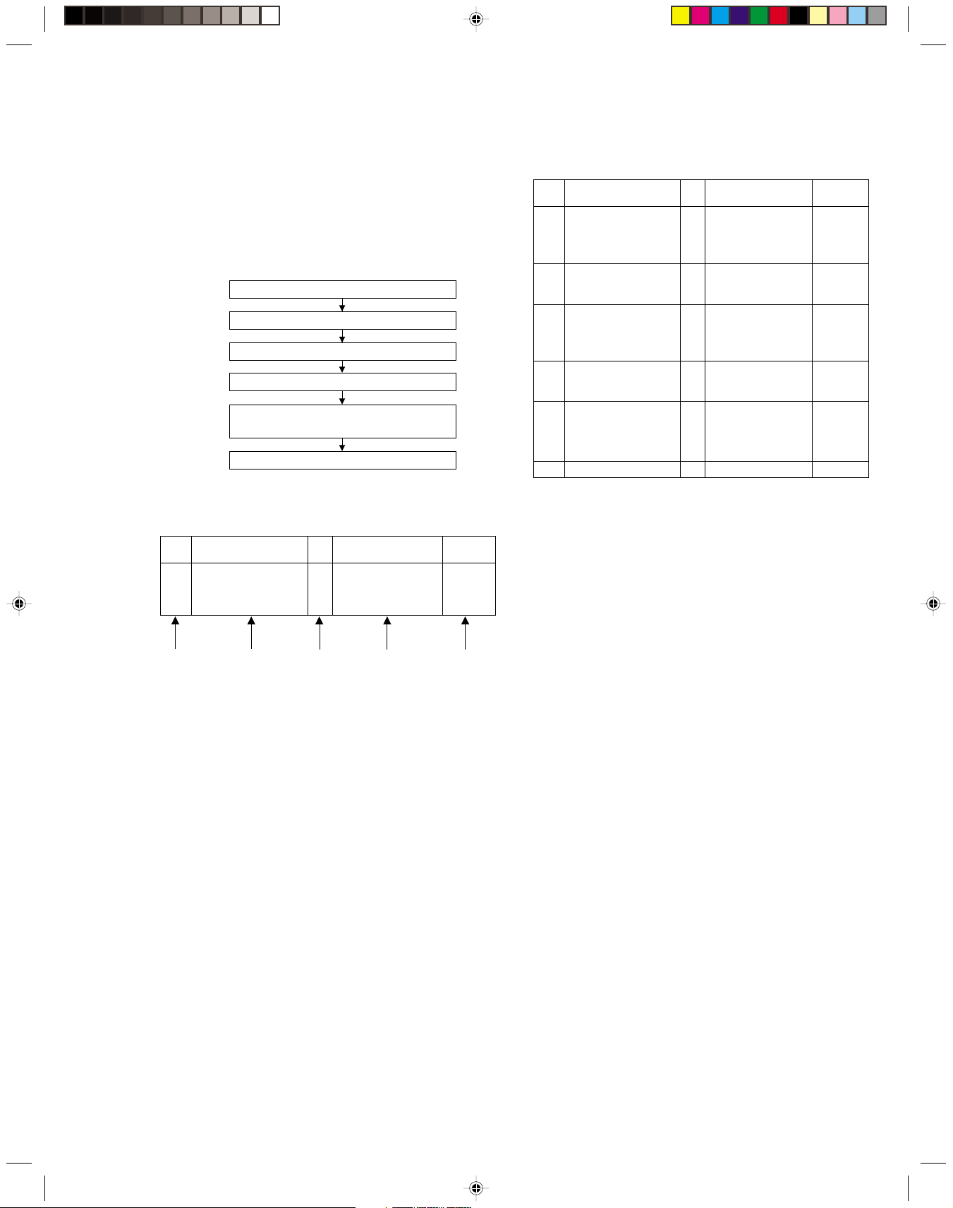
Procedures for Lowering the Cassette holder assembly
As the mechanism of this unit is integrated with the Housing
assembly, the holder must be lowered and the two screws unscrewed when removing the Mechanism assembly.
(L2a)
[VR620/77, VR625/77]
(A)
(B)
Fig. 2
Fig. 1
Fig. 3
Turn the loading motor pulley in the direction as indicated by
Fig.2. As both (A) and (B) levers are lodged twice, push the
levers in the direction as indicated by Fig.3 to release them.
When pushing the levers, do it in the order of (A), (B), (B),
(A). When the holder has been lowered, turn the pulley until
the cassette holder is securely in place without allowing any
up/down movement.
Procedures for Lowering the Cassette holder assembly
(S1a)
[VR620/77, VR625/77]
(S1b)
(L2a)
<Note 2b>
(L2a)
[2]
Front panel
assembly
“a”
(L2a)
[VR620/77, VR625/77]
(L2a)
“b”
<Note 2a>
Fig. D2
Note:
When installing the Drum assembly, secure the screws (S3a to
S3c) in the order of a, b, c.
(S1c)
Inertia plate
(S1c)
[1]
Bracket
[1] Top cover
(S1a)
Roller arm
assy
(L3a)
Not used
[3]
Drum
assembly
(S3a)
(P3)
(L3b)
Fig. D1 Fig. D3
(S3c)
CN1
CON1
WR3a
<Note 3a>
(S3b)
WR3b
<Note 3a>
Cleaner assy
(L3a)
1-2
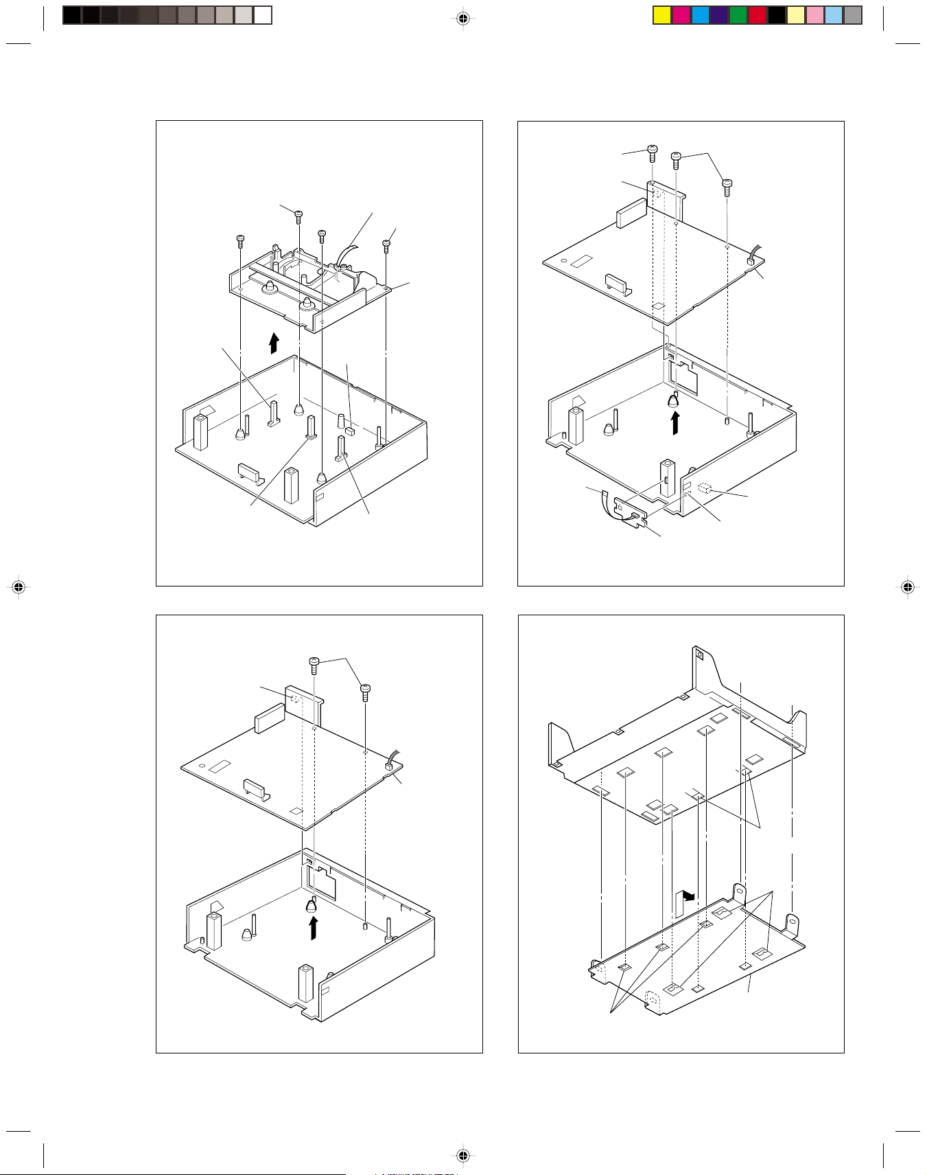
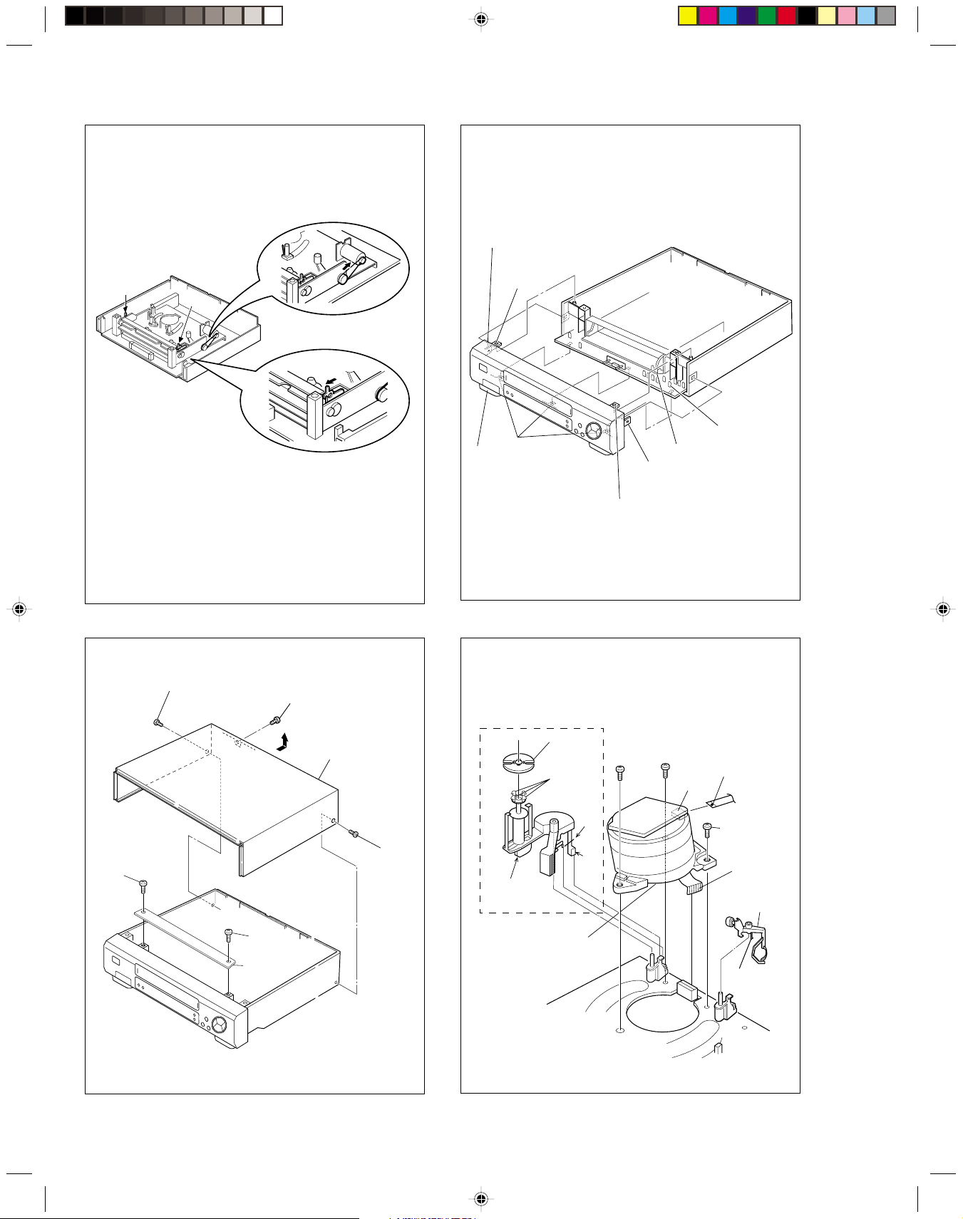
Note:
[6]
Bottom cover
(L6b)
(L6b)
(L6a)
<Note 6a>
When installing the Mechanism assembly, secure the
screws (S4a to S4b) in the order of a, b.
WR4a
<Note 3a>
(S4c)
(S4b)
<Note 4a>
(S4c)
(S4a)
<Note 4a>
(S5a)
(L5a)
(S5b)
Q3002
End sensor
<Note 4a>
D3001
LED
<Note 4a>
CN2001
Fig. D4
[4]
Mechanism
assembly
Q3001
Start sensor
[VR620/77, VR625/77]
<Note 4a>
(S5a)
WR5a
<Note 3a>
CN7001
(L5a)
[5] Mini front board assembly
[VR620/77, VR625/77]
Fig. D5b
[5]
Main board
assembly
(L5a)
Fig. D5a
[5]
Main board
assembly
[VR407/77]
Fig. D8
1-3
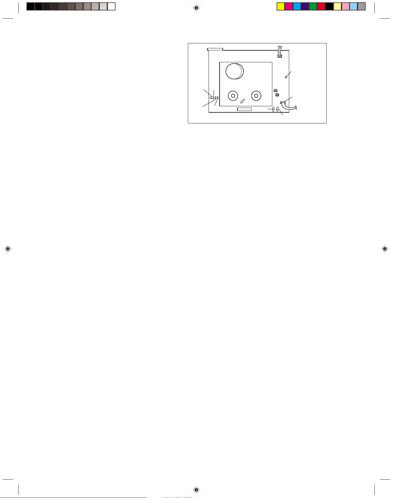
1.4 Service position
This unit has been designed so that the Mechanism and
Main board assemblies can be removed together from the
chassis assembly. Before diagnosing or servicing the circuit boards, take out the major parts from the chassis assembly.
1.4.1 How to set the “Service position”
(1) Refer to the disassembly procedure and perform the dis-
assembly of the major parts before removing the Drum
assembly.
(2) Lower the cassette holder to prepare for the removal of
the Mechanism assembly screws. (Refer to the “Proce-
dures for lowering the Cassette holder assembly” of 1.3
Disassembly/assembly method.)
(3) Remove the combined Mechanism and Main board as-
semblies.
(4) Connect the wires and connectors of the major parts that
have been removed in step (1). (Refer to Fig.1-4-1a.)
(5) Place the combined Mechanism and Main board assem-
blies upside down.
(6) Insert the power cord plug into the power outlet and then
proceed with the diagnostics and servicing of the board
assembly.
Notes:
• Before inserting the power cord plug into the power
outlet, make sure that none of the electrical parts are
able to short-circuit between the workbench and the
board assembly.
• For the disassembly procedure of the major parts and
details of the precautions to be taken, see “1.3 Disassembly/assembly method”.
• If there are wire connections from the Main board and
Mechanism assemblies to the other major parts, be
sure to remove them ( including wires connected to the
major parts ) first before performing step (2).
• When carrying out diagnosis and repair of the Main
board assembly in the “Service position”, be sure to
ground both the Main board and Mechanism assemblies. If they are improperly grounded, there may be
noise on the playback picture or FDP counter display
may move even when the mechanism is kept in an inoperative status.
• In order to diagnose the playback or recording of the
cassette tape, set the Mechanism assembly to the required mode before placing it upside down. If the
mechanism mode is changed (including ejection) while
it is in an upside down position the tape inside may
be damaged.
• The mechanism and board assemblies of this unit are
attached by connectors only.
When carrying out a diagnosis or repair of the boards
in the “Service position”, make sure that the connectors are not disconnected.
Main board
assembly
TP2253
A.PB.FM
[VR620/77,
TP106
VR625/77]
TP4001
CTL.P
PB.FM
TP111
D.FF
C3018
Timer clock
TPGND
CP4001
CP5302
TP7001
TEST
CN7001
[VR620/77, VR625/77]
To Mini front board
assembly
[VR620/77, VR625/77]
Fig. 1-4-1a
1.5 Mechanism service mode
This model has a unique function to enter the mechanism
into every operation mode without loading of any cassette
tape. This function is called the “Mechanism service mode”.
1.5.1 How to set the “Mechanism service mode”
(1) Unplug the power cord plug from the power outlet.
(2) Connect TPGND and TP7001(TEST) on the Main board
assembly with a jump wire.
(3) Insert the power cord plug into the power outlet.
(4) With lock levers (A) (B) on the left and right of the Cas-
sette holder assembly pulled toward the front, slide the
holder in the same direction as the cassette insertion di-
rection. (For the positions of lock levers (A) (B), refer to
the “Procedures for lowering the Cassette holder assem-
bly” of 1.3 Disassembly/assembly method.)
(5) The cassette holder lowers and, when the loading has
completed, the mechanism enters the desired mode.
1.6 Jig RCU mode
This unit uses the following two modes for receiving remote
control codes.
1) User RCU mode : Ordinary mode for use by the user.
2) Jig RCU mode : Mode for use in production and serv-
icing.
When using the Jig RCU, it is required to set the VCR to
the Jig RCU mode (the mode in which codes from the Jig
RCU can be received). As both of the above two modes
are stored in the EEPROM, it is required to set the VCR
back to the User RCU mode each time that an adjustment
is made or to check that the necessary operations have
been completed. These modes can be set by the operations described below.
1.6.1 Setting the Jig RCU mode
(1) Unplug the power cord plug from the power outlet.
(2) Press and hold the “REC” and “PAUSE” buttons on the
VCR simultaneously, while plugging the power cord plug
into the power outlet.
When the VCR is set to the Jig RCU mode, the symbols
( “ : ” ) in the time display of the FDP are turned off.
1-4
1.6.2 Setting the User RCU mode
(1) Turn off the power.
(2) Press the “REC” and “PAUSE” buttons of the VCR si-
multaneously. Alternatively, transmit the code “80” from
the Jig RCU.
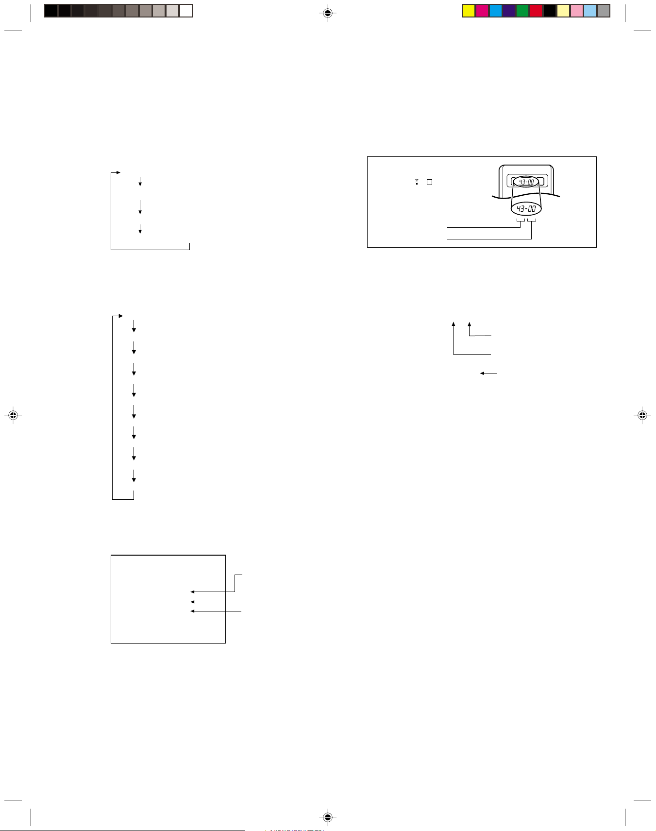
1.7 Emergency display function
This unit has a function for storing the history of the past two
emergencies (EMG) and displaying them on each FDP (or
OSD). With the status of the VCR and mechanism at the moment an emergency occurred can also be confirmed.
FDP display model
[FDP display]
0 : 00 : 00
E:**:**
*1 : *2 : 34
*5: *6 : *7
FDP (7segment LED) display model
[FDP display]
0: 00
E: **
1: **
2: *1
3: *2
4: 34
5: *5
6: *6
7: *7
OSD display model
[OSD display]
Normal display
EMG content display
(E:Latest:Previous)
EMG detail information <1>
EMG detail information <2>
Normal display
EMG content display (Latest)
EMG content display (Previous)
EMG detail information <1>
[Deck operation mode]
EMG detail information <1>
[Mechanism operation mode]
EMG detail information <1>
[Mechanism sensor information and Mechanism mode position]
EMG detail information <2>
[Type of the cassette tape in use <1>]
EMG detail information <2>
[Winding position of the cassette tape in use]
EMG detail information <2>
[Type of the cassette tape in use <2> (Winding area)]
EMG
E: **:**
*1 : *2 : 34
*5: *6 : *7
EMG content display
(E:Latest:Previous)
EMG detail information <1>
EMG detail information <2>
Notes:
•
The EMG detail information <1><2> show the information
on the latest EMG.
It becomes “ – – : – – : – –” when there is no latest EMG
record.
•
When using the Jig RCU, it is required to set the VCR to
the Jig RCU mode (the mode in which codes from the Jig
RCU can be received).
Jig RCU
[Data transmitting method]
Depress the “ ” ( 3 ) button
after the data code is set.
CUSTOM CODE
43: A CODE
53: B CODE
DATA CODE
INITIAL MODE
Fig. 1-7a Jig RCU
1.7.1 Displaying the EMG information
(1) Transmit the code “59” from the Jig RCU.
The FDP shows the EMG content in the form of “E:**:**”.
<Example 1> E : 01 : 03
Previous EMG
Latest EMG
<Example 2> E : –– : ––
No EMG record
(2) Transmit the code “59” from the Jig RCU again.
The FDP shows the EMG detail information <1> in the form
of “ * 1 : * 2 : 34 ”.
* 1 : Deck operation mode at the moment of EMG
* 2 : Mechanism operation mode at the moment of EMG
3– : Mechanism sensor information at the moment of
EMG
–4 : Mechanism mode position at the moment of EMG
(3) Transmit the code “59” from the Jig RCU once again.
The FDP shows the EMG detail information <2> in the form
of “ *5 : *6 : *7 ”.
* 5 : Type of the cassette tape in use <1> .
* 6 : Winding position of the cassette tape in use
* 7 : Type of the cassette tape in use <2> (Winding area)
(4) Transmit the code “59” from the Jig RCU once again to re-
set the display.
Notes:
•
For the OSD display model, all EMG information are
showed by transmitting first code from the Jig RCU.
•
For the EMG content, see “1.7.3 EMG content description”.
•
For the EMG detail information <1> , see “1.7.4 EMG detail information <1> ”.
•
For the EMG detail information <2> , see “1.7.5 EMG detail information <2>”.
1.7.2 Clearing the EMG history
(1) Display the EMG history.
(2) Transmit the code “36” from the Jig RCU.
(3) Reset the EMG display.
(EMG-02e)
1-5

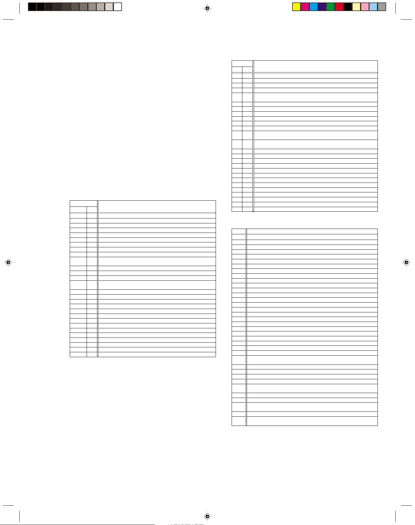
1.7.3 EMG content description
EMG contents “E08/E09” are for the model with Dynamic Drum (DD).
Note:
FDP CONTENT CAUSE
E01: Loading EMG
E02:
Unloading EMG
E03: Take Up Reel
Pulse EMG
E04: Drum FG
EMG
E05: Cassette Eject
EMG
E06: Capstan FG
EMG
E07: SW Power
Short-Circuit
EMG
E08:
DD Initialized
(Absolute
Position
Sensor)
EMG
E09: DD FG EMG
E0A:Supply Reel
Pulse EMG
EC1 or EU1:
Head clog warning
When the mechanism mode cannot be changed to another mode even when the loading motor has rotated
for more than 4 seconds in the loading direction, [E:01]
is identified and the power is turned off.
When the mechanism mode cannot be changed to another mode even when the loading motor has rotated
for more than 4 seconds in the unloading direction, [E:02]
is identified and the power is turned off.
When the take-up reel pulse has not been generated for
more than 4 seconds in the capstan rotating mode, [E:03]
is identified, the pinch rollers are turned off and stopped,
and the power is turned off. However, the reel EMG is
not detected in STILL/SLOW modes.
When the drum FG pulse has not been input for more
than 3 seconds in the drum rotating mode, [E:04] is identified, the pinch rollers are turned off and stopped, and
the power is turned off.
When the eject operation does not complete in 3 seconds after the start, [E:05] is identified, the pinch rollers
are turned off and stopped, and the power is turned off.
When the cassette insertion operation does not complete
in 3 seconds after the start, the cassette is ejected. In
addition, when the operation does not complete within
3 seconds after the start, [E:05] is also identified and the
power is turned off immediately.
When the capstan FG pulse has not been generated for
more than 1 second in the capstan rotating mode, [E:06]
is identified, the pinch rollers are turned off and stopped,
and the power is turned off.However, the capstan EMG
is not detected in STILL/SLOW/FF/REW modes.
When short-circuiting of the SW power supply with GND
has lasted for 0.5 second or more, [E:07] is identified,
all the motors are stopped and the power is turned off.
When DD tilting does not complete in 4 seconds, [E:08]
is identified, the tilt motor is stopped and the power is
turned off.
When the DD FG pulse is not generated within 2.5 seconds, [E:09] is identified, the tilt motor is stopped and
the power is turned off.
When the supply reel pulse has not been generated for
more than 10 seconds in the capstan rotating mode,
[E:0A] is identified and the cassette is ejected (but the
power is not turned off). However, note that the reel EMG
is not detected in the SLOW/STILL mode.
Presupposing the presence of the control pulse output in the PLAY mode, when the value obtained by mixing the two V.FM output
channels (without regard to the A.FM output) has remained below a certain threshold level for more than 10 seconds, [E:C1] or [E:U1]
is identified and recorded in the emergency history. During the period in which a head clog is detected, the FDP and OSD repeat the
“3-second warning display” and “7-second noise picture display” alternately.
EMG code : “E:C1” or “E:U1” / FDP : “U:01” / OSD : “Try cleaning tape.” or “Use cleaning cassette.”
The head clog warning is reset when the above-mentioned threshold has been exceeded for more than 2 seconds or the mode is
changed to another mode than PLAY.
The mechanism is locked in the middle of mode transition.
1.
2
. The mechanism is locked at the loading end due to the encoder position
reading error during mode transition.
3.
Power is not supplied to the loading MDA.
1.
The mechanism is locked in the middle of mode transition.
2.
The mechanism is locked at the unloading end due to the encoder position reading error during mode transition.
3.
Power is not supplied to the loading MDA.
1.
The take-up reel pulse is not generated in the FWD transport modes (PLAY/
FWD SEARCH/FF, etc.) because;
1) The idler gear is not meshed with the take-up reel gear;
The idler gear is meshed with the take-up reel gear, but incapable of wind-
2)
ing due to too large mechanical load (abnormal tension);
3) The take-up reel sensor does not output the FG pulse.
2.
The supply reel pulse is not generated in the REV transport modes (REV
SEARCH/REW, etc.) because;
1) The idler gear is not meshed with the supply reel gear.
2) The idler gear is meshed with the supply reel gear, but incapable of wind-
ing due to too large a mechanical load (abnormal tension);
3) The supply reel sensor does not output the FG pulse.
3.
Power is not supplied to the reel sensors.
1.
The drum could not start or the drum rotation has stopped due to too large
a load on the tape, because;
1) The tape tension is abnormally high;
The tape is damaged or a foreign object (grease, etc.) adheres to the tape.
2)
2.
The drum FG pulse did not reach the System controller CPU because;
1) The signal circuit is disconnected in the middle;
2) The FG pulse generator (hall device) of the drum is faulty.
3.
The drum control voltage (DRUM CTL V) is not supplied to the MDA.
4.
Power is not supplied to the drum MDA.
1.
The cassette cannot be ejected due to a failure in the drive mechanism of
the housing.
2.
When the housing load increases during ejection, the loading motor is
stopped because of lack of headroom in its drive torque.
Housing load increasing factors: Temperature environment (low temperature, etc.), mechanism wear or failure.
3.
The sensor/switch for detecting the end of ejection are not functioning normally.
4.
The loading motor drive voltage is lower than specified or power is not supplied to the motor (MDA).
5.
When the user attempted to eject a cassette, a foreign object (or perhaps
the user's hand) was caught in the opening of the housing.
1.
The capstan could not start or the capstan rotation has stopped due to too
large a load on the tape, because;
1) The tape tension is abnormally high (mechanical lock);
2) The tape is damaged or a foreign object (grease, etc.) is adhered to the
tape (occurrence of tape entangling, etc.).
2.
The capstan FG pulse did not reach the System controller CPU because;
1) The signal circuit is disconnected in the middle;
2) The FG pulse generator (MR device) of the capstans is faulty.
3.
The capstan control voltage (CAPSTAN CTL V) is not supplied to the MDA.
4.
Power is not supplied to the capstan MDA.
1.
The SW 5 V power supply circuit is shorted with GND.
2.
The SW 12 V power supply circuit is shorted with GND.
1. The absolute value sensor is defective. (The soldered parts have separated.)
2. The pull-up resistor at the absolute sensor output is defective. (The soldered parts
have separated.)
3. Contact failure or soldering failure of the pins of the connector (board-to-board) to the
absolute value sensor.
The absolute value sensor data is not sent to the System Controller CPU.
4.
1. The FG sensor is defective. (The soldered parts have separated.)
2. The pull-up resistor at the FG sensor output is defective. (The soldered parts have
separated.)
3. Contact failure or soldering failure of the pins of the connector (board-to-board) to the FG sensor.
4. The power to the sensor is not supplied. (Connection failure/soldering failure)
5. The FG pulse is not sent to the System Controller CPU.
The tilt motor is defective. (The soldered parts have separated.)
6.
7. The drive power to the tilt motor is not supplied. (Connection failure/soldering failure)
8. The tilt motor drive MDA - IC is defective.
9. Auto-recovery of the DD tilting cannot take place due to overrun.
1.
The supply reel pulse is not generated in the FWD transport mode (PLAY/
FWD SEARCH/FF, etc.) because;
1) PLAY/FWD or SEARCH/FF is started while the tape in the inserted cas-
sette is cut in the middle;
2) A mechanical factor caused tape slack inside and outside the supply
reel side of the cassette shell. In this case, the supply reel will not rotate
until the tape slack is removed by the FWD transport, so the pulse is not
generated until then;
3) The FG pulse output from the supply reel sensor is absent.
2.
The take-up reel pulse is not generated in the REV transport mode (REV
SEARCH/REW, etc.).
1) REV SEARCH/REW is started when the tape in the inserted cassette
has been cut in the middle;
2) A mechanical factor caused tape slack inside and outside the take-up
reel side of the cassette shell. In this case, the supply reel will not rotate
until the tape slack is removed by the REV transport, so the pulse will
not be generated until that time;
3) The FG pulse output from the take-up reel sensor is absent.
3.
The power to a reel sensor is not supplied.
1-6
Table 1-7-3a
1.7.4 EMG detail information <1>
The status (electrical operation mode) of the VCR and the status (mechanism operation mode/sensor information) of the
mechanism in the latest EMG can be confirmed based on the
figure in EMG detail information <1> .
[FDP/OSD display]
* 1 : * 2 : 34
* 1 : Deck operation mode at the moment of EMG
* 2 : Mechanism operation mode at the moment of EMG
3– : Mechanism sensor information at the moment of EMG
–4 : Mechanism mod
e position at the moment of EMG
Note:
•
For EMG detailed information <1>, the content of the code
that is shown on the FDP (or OSD) differs depending on
the parts number of the system control microprocessor
(IC3001) of the VCR. The system control microprocessor
parts number starts with two letters, refer these to the corresponding table.
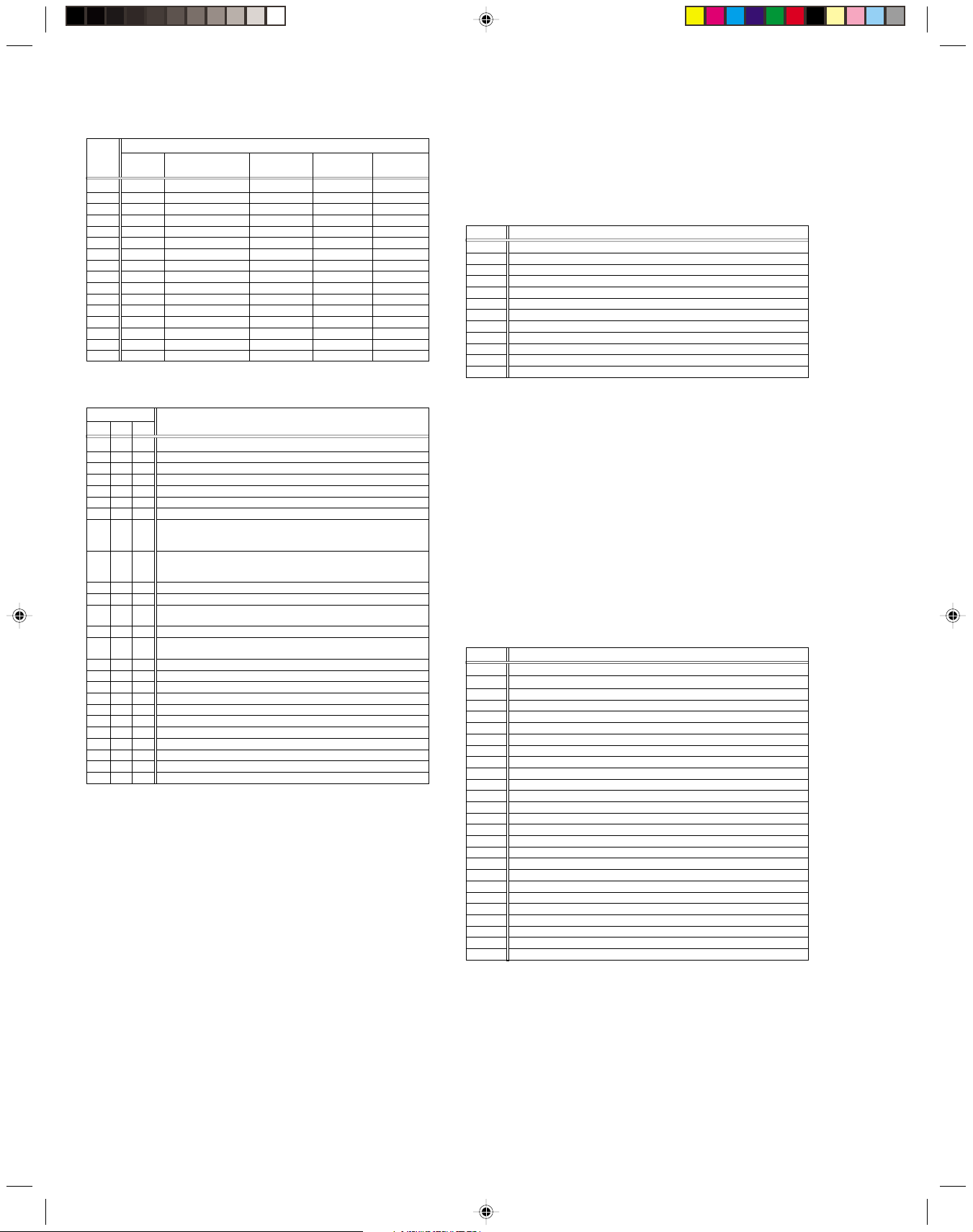
* 1 : Deck operation mode
[Common table of MN*, HD* and M3*]
Display
MN*/M3* HD*
00 - Mechanism being initialized
01 00 STOP with pinch roller pressure off (or tape present with P.OFF)
02 01 STOP with pinch roller pressure on
03 - POWER OFF as a result of EMG
04 04 PLAY
0C 0E REC
10 11 Cassette ejected
20 22 FF
21 - Tape fully loaded, START sensor ON, short FF
22 - Cassette identification FWD SEARCH before transition to FF (SP
24 26 FWD SEARCH (variable speed) including x2-speed
2C 2E INSERT REC
40 43 REW
42 - Cassette identification REV SEARCH before transition to REW (SP
44 47 REV SEARCH (variable speed)
4C 4C AUDIO DUB
6C 6E INSERT REC (VIDEO + AUDIO)
84 84 FWD STILL / SLOW
85 85 REV STILL / SLOW
8C 8F REC PAUSE
8D - Back spacing
8E - Forward spacing (FWD transport mode with BEST function)
AC AF INSERT REC PAUSE
AD - INSERT REC back spacing
CC CD AUDIO DUB PAUSE
CD - AUDIO DUB back spacing
EC EF INSERT REC (VIDEO + AUDIO) PAUSE
ED - INSERT REC (VIDEO + AUDIO) back spacing
x7-speed)
x7-speed)
Deck operation mode
* 2 : Mechanism operation mode
[Common table of MN* and M3*]
Display
MN* M3*
00 00 Command standby (Status without executing command)
02 02 POWER OFF by EMG occurrence
04 04 Moving to the adjacent position in the LOAD direction
06 06 Moving to the adjacent position in the UNLOAD direction
08 08 Cassette ejection being executed / Cassette housing ejection being
- 0A Mode transition to STOP with cassette ejection end
0A 0C Cassette insertion being executed
0C 0E Tape being loaded
0E 10 Tape being unloaded
10 12 Mode transition to STOP with pinch roller compression ON
12 14 Mode transition to STOP with pinch roller compression OFF
14 16
16 18
18 1A Mode transition to PLAY
1A 1C Mode transition to FWD SEARCH
1C 1E Mode transition to REC
1E 20 Mode transition to FWD STILL / SLOW
20 22 Mode transition to REV STILL / SLOW
22 24 Mode transition to REV SEARCH
24 26 Mode transition from FF / REW to STOP
26 28 Mode transition to FF
28 2A Mode transition to REW
2A 2C 4 sec. of REV as a result of END sensor going ON during loading
2C 2E
2E 30 Mechanism position being corrected due to overrun
80 80 Mechanism in initial position (Dummy command)
executed
Mode transition to STOP with pinch roller compression OFF as a result
of POWER OFF
Mode transition to STOP with pinch roller compression ON as a result
of POWER ON
Short FF / REV as a result of END sensor going ON during unloading
Mechanism operation mode
[Table of HD*]
Display
00 STOP with pinch roller pressure off
01 STOP with pinch roller pressure on
02 U/L STOP (or tape being loaded)
04 PLAY
05 PLAY (x1-speed playback using JOG)
0E REC
11 Cassette ejected
22 FF
26 FWD SEARCH (variable speed) including x2-speed
2E INSERT REC
43 REW
47 REV SEARCH
4C AUDIO DUB
6E INSERT REC (VIDEO + AUDIO)
84 FWD STILL/SLOW
85 REV STILL/SLOW
8F REC PAUSE
AF INSERT REC PAUSE
C7 REV SEARCH (x1-speed reverse playback using JOG)
CD AUDIO DUB PAUSE
EF INSERT REC (VIDEO + AUDIO) PAUSE
F0 Mechanism being initialized
F1 POWER OFF as a result of EMG
F2 Cassette being inserted
F3 Cassette being ejected
F4 Transition from STOP with pinch roller pressure on to STOP with pinch
roller pressure off
F5 Transition from STOP with pinch roller pressure on to PLAY
F6 Transition from STOP with pinch roller pressure on to REC
F7 Cassette type detection SEARCH before FF/REW is being executed
F8 Tape being unloaded
F9 Transition from STOP with pinch roller pressure off to STOP with pinch
roller pressure on
FA Transition from STOP with pinch roller pressure off to FF/REW
FB Transition from STOP with pinch roller pressure off to REC.P (T.REC,etc.)
FC Transition from STOP with pinch roller pressure off to cassette type de-
tection SEARCH
FD Short REV being executed after END sensor on during unloading
FE Tension loosening being executed after tape loading (STOP with pinch
roller pressure on)
Mechanism operation mode
1-7
3– : Mechanism sensor information
[Common table of MN*, HD* and M3*]
Display
MN* / HD* M3* REC safety Start End
S-VHS SW CASS SW SW sensor sensor
0- VHS Cassette insertion Tab broken ON ON
1- VHS Cassette insertion Tab broken ON OFF
2- VHS Cassette insertion Tab broken OFF ON
3- VHS Cassette insertion Tab broken OFF OFF
4- VHS Cassette insertion Tab present ON ON
5- VHS Cassette insertion Tab present ON OFF
6- VHS Cassette insertion Tab present OFF ON
7- VHS Cassette insertion Tab present OFF OFF
8- S-VHS Cassette ejection Tab broken ON ON
9- S-VHS Cassette ejection Tab broken ON OFF
A- S-VHS Cassette ejection Tab broken OFF ON
B- S-VHS Cassette ejection Tab broken OFF OFF
C- S-VHS Cassette ejection Tab present ON ON
D- S-VHS Cassette ejection Tab present ON OFF
E- S-VHS Cassette ejection Tab present OFF ON
F- S-VHS Cassette ejection Tab present OFF OFF
Mechanism sensor information
–4 : Mechanism mode position
[Common table of MN*, HD* and M3*]
Display Mechanism mode position
MN* HD* M3*
-0 -7 - Initial value
-1 -0 - EJECT position
- - -0 EJECT position (Cassette housing drive mode)
-2 -7 - Housing operating
- - -1 Between EJECT and U / L STOP
-3 -1 -2 U / L STOP position
- - -3 Guide arm drive position
-4 -7 -4 Tape being loaded / unloaded (When the pole base is
-5 -2 -5 Tape being loaded / unloaded (When the pole base is
-6 -7 -6 Pole base compressed position
-7 -3 -F FF / REW position
-8 -7 -F Between FF / REW and STOP with pinch roller compres-
-9 -4 -F STOP with pinch roller compression OFF
-A -7 -E Between STOP with pinch roller compression OFF and
-B -5 - REV (REV STILL / SLOW) position
- - -D REV position
- - -C Between REV and REV STILL / SLOW
- - -B REV STILL / SLOW position
-C -7 - Between REV and FWD
- - -A Between REV STILL / SLOW and FWD STILL / SLOW
-D -6 - FWD (FWD STILL / SLOW) position
- - -9 FWD STILL / SLOW position
-E -7 - Between FWD and PLAY
- - -8 Between FWD STILL / SLOW and PLAY
-F -6 -7 PLAY position
located on the front side of the position just beside the
drum)
located on the rear side of the position just beside the
drum)
sion ON
REV
Note:
• In the case of the "HD*” microprocessor, as the display is
always "-7” at any intermediate position between modes,
the position of transitory EMG may sometimes not be located.
1.7.5 EMG detail information <2>
The type of the cassette tape and the cassette tape winding position can be confirmed based on the figure in EMG detail information <2> .
[FDP/OSD display]
*5 : *6 : *7
* 5 : Type of the cassette tape in use <1>
* 6 : Winding position of the cassette tape in use
* 7 : Type of th
e cassette tape in use
<2>
(Winding area)
Note:
• EMG detail information <2> is the reference information
stored using the remaining tape detection function of the
cassette tape. As a result, it may not identify cassette correctly when a special cassette tape is used or when the
tape has variable thickness.
* 5 : Cassette tape type <1>
Display Cassette tape type <1>
00 Cassette type not identified
16
Large reel/small reel (T-0 to T-15/T-130 to T-210) not classified
82 Small reel, thick tape (T-120) identified/thin tape (T-140) identified
84 Large reel (T-0 to T-60) identified
92
Small reel, thick tape (T-130) identified/thin tape (T-160 to T-210) identified
93
Small reel, thick tape/C cassette (T-0 to T-100/C cassette) not classified
C3
Small reel, thick tape/C cassette (T-0 to T-100/C cassette) being classified
D3
Small reel, thick tape/C cassette (T-0 to T-100/C cassette) being classified
E1 C cassette, thick tape (TC-10 to TC-20) identified
E2 Small reel, thick tape (T-0 to T-100) identified
E9 C cassette, thin tape (TC-30 to TC-40) identified
F1
C cassette, thick tape/thin tape (TC-10 to TC-40) not classified
Notes:
•
Cassette tape type
<1>
is identified a few times during mode
transition and the identification count is variable depending on
the cassette tape type. If an EMG occurs in the middle of identification, the cassette tape type may not be able to be identified.
•
If other value than those listed in the above table is displayed,
the cassette tape type is not identified.
* 6 : Cassette tape winding position
The cassette tape winding position at the moment of EMG is
displayed by dividing the entire tape (from the beginning to the
end) in 22 sections using a hex number from “00” to “15”.
“00” : End of winding
“15” : Beginning of winding
“FF or ––” : Tape position not identified
* 7 : Cassette tape type <2> (Winding area)
Display Cassette tape type <2>
00 Cassette type not identified
07 Small reel, thick tape T-5
08 - 0E C cassette, thick tape TC-10
09 - 15 C cassette, thick tape TC-20P
0A - 0B Small reel, thick tape T-20
0A - 16 C cassette, thin tape TC-30
0A - 16 C cassette, thin tape TC-40
0D - 0F Small reel, thick tape T-40
11 - 14 Small reel, thick tape T-60
15 - 18 Small reel, thick tape T-80 / DF-160
17 - 1A Small reel, thick tape T-90 / DF-180
19 - 1D Small reel, thick tape T-100
1D - 21 Small reel, thick tape T-120 / DF-240
1E - 1F Small reel, thin tape T-140
1F - 23 Small reel, thick tape T-130
21 - 23 Small reel, thin tape T-160
21 - 23 Small reel, thin tape T-168
22 - 24 Small reel, thick tape DF-300
22 - 24 Small reel, thin tape T-180 / DF-360
22 - 24 Small reel, thin tape T-210 / DF-420
22 - 23 Large reel T-5
23 - 24 Large reel T-10
25 - 26 Large reel T-20
27 - 29 Large reel T-30
29 - 2B Large reel T-40
2D - 2F Large reel T-60
Note:
•
The values of cassette tape type <2> in the above table
are typical values with representative cassette tapes.
1-8
SECTION 2
Press
(C)
(A)
(B)
MECHANISM ADJUSTMENT
2.1 Before starting repair and adjustment
2.1.1 Precautions
(1) Unplug the power cord plug of the VCR before using your
soldering iron.
(2) Take care not to cause any damage to the conductor
wires when plugging and unplugging the connectors.
(3) Do not randomly handle the parts without identifying
where the trouble is.
(4) Exercise enough care not to damage the lugs, etc. dur-
ing the repair work.
(5) When reattaching the front panel assembly, make sure
that the door opener of the cassette holder assembly is
lowered in position prior to the reinstallation. (See SECTION 1 DISASSEMBLY.)
(6) When using the Jig RCU, it is required to set the VCR to
the Jig RCU mode (the mode in which codes from the
Jig RCU can be received). (See SECTION 1 DISASSEMBLY.)
Loading motor
2.1.2 Checking for proper mechanical operations
Enter the mechanism service mode when you want to operate the mechanism when no cassette is loaded. (See SECTION 1 DISASSEMBLY.)
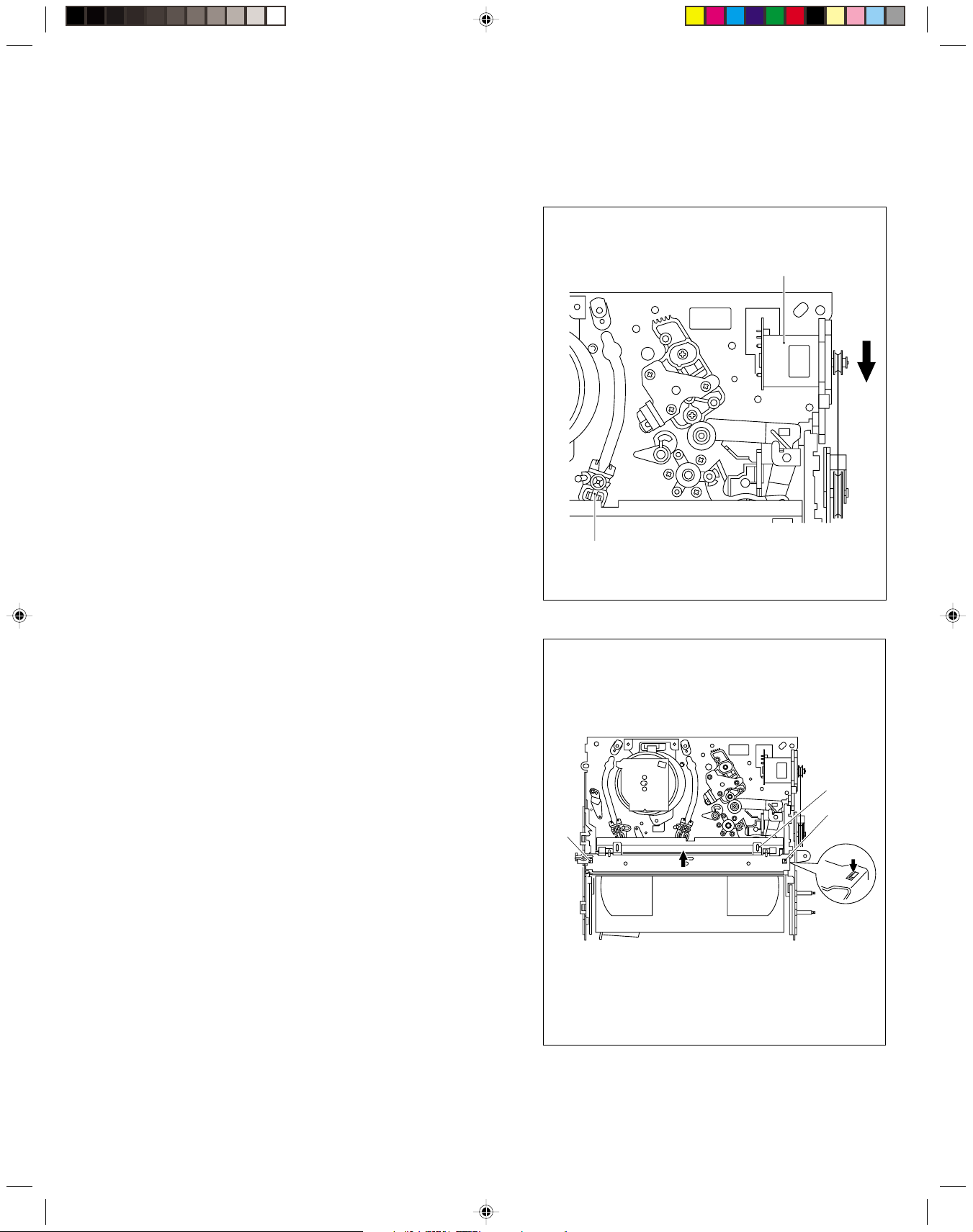
2.1.3 Manually removing the cassette tape
1. In case of electrical failures
If you cannot remove the cassette tape which is loaded because of any electrical failure, manually remove it by taking
the following steps.
(1) Unplug the power cord plug from the power outlet.
(2) Refer to the disassembly procedure and perform the dis-
assembly of the major parts before removing the drum
assembly.
(3) Unload the pole base assembly by manually turning the
loading motor of the mechanism assembly toward the
front. In doing so, hold the tape by the hand to keep the
slack away from any grease. (See Fig.2-1-3a.)
(4) Bring the pole base assembly to a pause when it reaches
the position where it is hidden behind the cassette tape.
(5) Move the top guide toward the drum while holding down
the lug (A) of the bracket retaining the top guide. Likewise hold part (B) down and remove the top guide.
Section (C) of the top guide is then brought under the
cassette lid. Then remove the top guide by pressing the
whole cassette tape down. (See Fig.2-1-3b.)
(6) Remove the cassette tape by holding both the slackened
tape and the cassette lid.
(7) Take up the slack of the tape into the cassette. This com-
pletes removal of the cassette tape.
Note:
• For the disassembly procedure of the major parts and
details of the precautions to be taken, see “SECTION
1 DISASSEMBLY”.
Pole base assembly
Fig. 2-1-3a
Fig. 2-1-3b
2-1
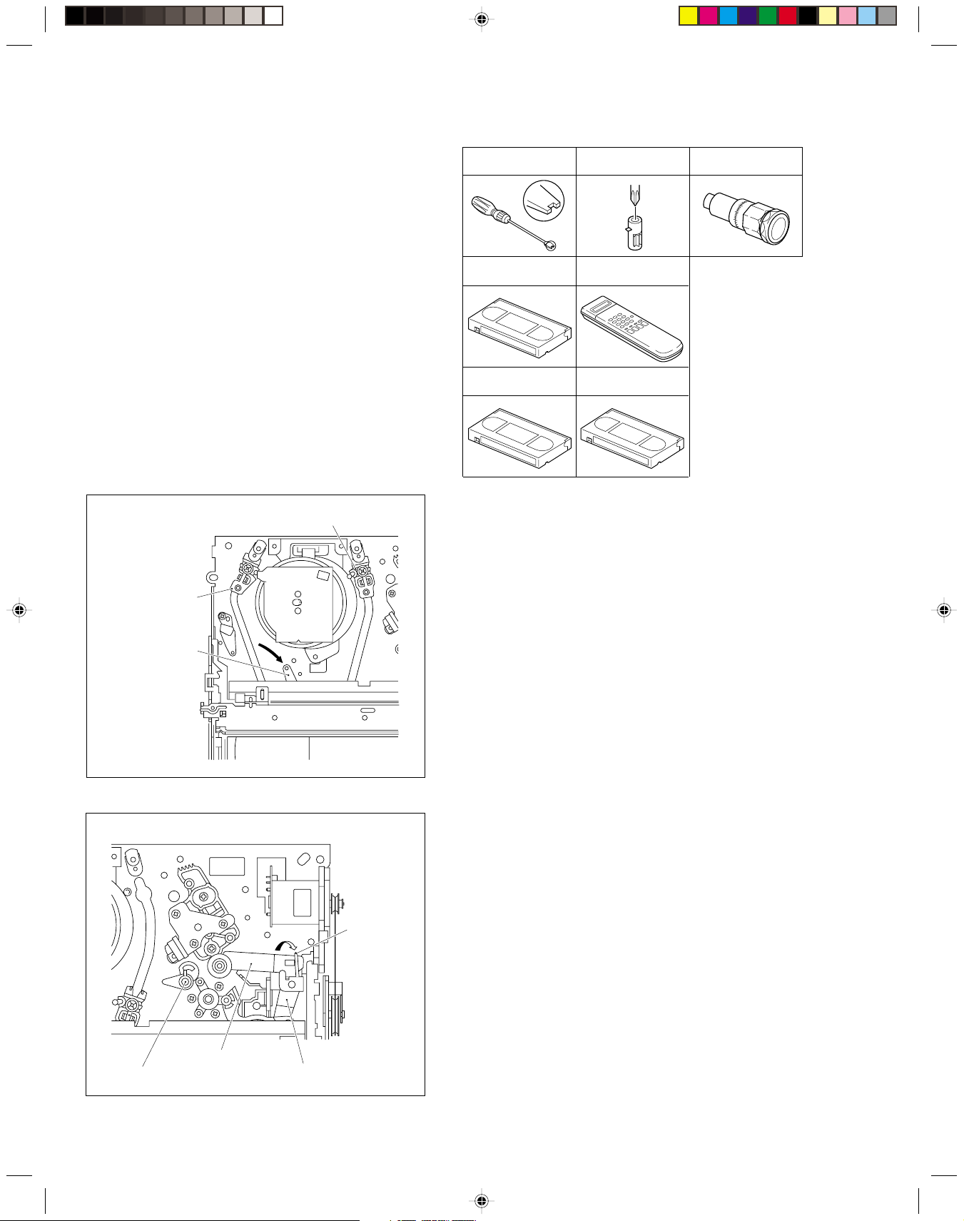
2. In case of mechanical failure
If you cannot remove the cassette tape which is loaded because of any mechanical failure, manually remove it by taking the following steps.
(1) Unplug the power cable and remove the top cover, front
panel assembly and others so that the mechanism assembly is visible. (See SECTION 1 DASASSEMBLY.)
(2) While keeping the tension arm assembly of the mecha-
nism assembly free from tension, pull the tape on the pole
base assembly (supply or take-up side) out of the guide
roller. (See Fig.2-1-3c.)
(3) Take the spring of the pinch roller arm assembly off the
hook of the press lever assembly, and detach it from the
tape. (See Fig.2-1-3d.)
(4) In the same way as in the electrical failure instructions in
2.1.3-1(5), remove the top guide.
(5) Raise the cassette tape cover. By keeping it in that posi-
tion, draw out the cassette tape case from the cassette
holder and take out the tape.
(6) By hanging the pinch roller arm assembly spring back
on the hook, take up the slack of the tape into the cassette.
Pole base assembly (take-up side)
2.1.4 Jigs and tools required for adjustment
Roller driver A/C head positioning tool
Back tension cassette gauge
Alignment tape
(SP, stairstep, PAL)
Alignment tape
(LP, stairstep, PAL)
Jig RCU
Torque gauge
Pole base assembly
(supply side)
Tension arm assembly
Fig. 2-1-3c
Take the spring
off the hook, and
detach it from the
tape.
Pinch roller arm assembly
Guide pole guard
2-2
Press lever assembly
Fig. 2-1-3d
 Loading...