

Philips VAE5020, VAM5020 Service Manual
Published by DP 0170 Service DPS Hasselt Printed in the Netherlands Subject to modification
3122 785 60030
©
Copyright 2001 Philips Consumer Electronics B.V. Eindhoven, The Netherlands.
All rights reserved. No part of this publication may be reproduced, stored in a
retrieval system or transmitted, in any form or by any means, electronic, mechanical,
photocopying, or otherwise without the prior permission of Philips.
Compact Disc Recorder 2nd Line Service Manual
CDR Mozart Module
CL 16532046_000.eps
030501
Contents Page Contents Page
1 Introduction and Technical Specifications 2
2 Safety- and Maintenance Instructions, Warnings
and Notes 4
3 Instructions for Use 7
4
Mechanical Instructions 7
Exploded View CDR-Module 8
Exploded View VAE5020 9
Exploded View VAM5020 10
Exploded View Freya Loader 11
5 Trouble Shooting 12
6
Block Diagrams
Block Diagram Freya Module 25
Block Diagram Mozart Back-End Module 26
7
Electrical Diagrams and PWB’s Diagram PWB
Mozart Main Board(Diagram 1) 27 32-37
Mozart Main Board(Diagram 2) 28 32-37
Mozart Main Board(Diagram 3) 29 32-37
Mozart Main Board(Diagram 4) 30 32-37
Mozart Main Board(Diagram 5) 31 32-37
Mozart Main Board Testpoints 38-40
Freya Servo Board(Overview) 41 46-47
Freya Servo Board(Part 1) 42 46-47
Freya Servo Board(Part 2) 43 46-47
Freya Servo Board(Part 3) 44 46-47
Freya Servo Board(Part 4) 45 46-47
Freya Servo Board Testpoints(Bottom View) 48
8 Alignments, Adjustments 49
9 Circuit and Functional Description 50
List of Abbreviations 56
10 Mechanical and Electrical Spare Parts List 58

Introduction / Technical Specifications
GB 2 CDR Mozart1.
1. Introduction / Technical Specifications
1.1 General
CD Recording Mozart Module is a module for playback of
Audio/Data CD’s (incl. CD R/W) and recording on Audio CDR and CD-R/W Disc consisting of:
• CD (Recording) Drive Mechanism
• Tray Loading Mechanism
• Front-end Board inclusive CD -Servo control Software
• Backend Board containing Application software
• Metal Encasing (for EMC Screening and mechanical
fixation)
Not included is the User Interface that has to be handled by
the Set front application. This user interface controls
functions that are set independently like: display and key
handling.
Note: The EMC screening is not mounted in some
applications.
The CD (Recording) Drive Mechanism, Tray Loading
Mechanism and Front-end Board part of the module can
have 2 different executions. One is called FREYA the other
RACOON. As information and repair activity about
RACOON is not defined yet, this part is not included in this
Service Manual.
Notice that both Mechanisms can not be interchanged, so
RACOON has to be replaced by RACOON, FREYA by
FREYA. As both parts can only be repaired with the help of
CDR-ComPair, the ComPair tool will contain the instructions
for both mechanisms.
1.2 Key Features / Functions
Playback Capability
• standard Audio/Data CD’s
– MP3/AAC audio format
– Software up-grade possibility via CD Disc
• fully (‘Red Book included CD-extra’) or unfinalized partly
recorded CD-R and CD-R/W Discs
Recording Capability
• Audio CD-R Discs
• Recording / Erasure of CD R/W Discs
Double speed recording (from EBU input only)
4x speed (only in some applications)
CD Text (Playback and Recording)
Audio Signal Inputs
• Analog (ADC on board)
• Digital (EBU)
Audio Signal Outputs
• Analog (DAC on board)
• Digital (EBU)
CD10 (Philips) CD-decoder connection for multiple CDplayback changers
1.3 Hardware interface
Interface connectors are located at the rear of the Module
and are accessible via a horizontal slot.
1.3.1 Connector 1214: Supply Interface
1. +5 V
2. +5 V
3. Ground (D)
4. Ground (D)
5. Ground (S) (motor ground)
6. +12 V
1.3.2 Connector 1007: Control Interface
1. Ground (D) / (Shield)
2. I
C-Data
3. Ground (D)
4. I
C Clock
5. Reset
6. IRQREQ
1.3.3 Connector 1402: Audio Signal Interface
1. Analog In (Rec.) Left
2. Ground (A)
3. Analog In (Rec.) Right
4. Ground (A)
5. Analog Out (PB)Right
6. Ground (A)
7. Analog Out (PB) Left
1.3.4 Connector 1203: Digital In / out
1. +5 V
2. EBU Signal (output)
3. EBU Signal (input - optical) /Ground(D)
4. EBU Signal (input Coax)
5. Ground (D)
1.3.5 Connector 1205: CD Interface for MP3 Playback
1. Ground
2. SDA (output / input)
3. SICL
4. RAB
5. SILD
6. Reset CD10
7. EBU Signal (input)
8. EBU Ground
1.3.6 Connector 1215: I/O Interface for Separate AD/DA
connections
1. EBU_OUT_ENGINE/GND
2. PROF_DIG_OUT/GND
3. EBU_CD10
4. GND
5. IIS_DATA1 / GND
6. IIS_CLK1 / GND
7. DEEMP
8. IIS_WLK1/GND
9. PWR_ON_RESET
10. IIS_CLK4
11. GND
12. IIS_WLK4
13. MUTE
14. IIS_DATA4
15. GND
16. CLK_16
17. KILL
1.3.7 Connector 1209: External DAC and ADC interface for
Better AD/DA (Optional)
1. MUTE
2. I2S_CLK2
3. GND
4. I2S_WS2
5. DEEMP
6. I2S_DATAO2
7. GND

Introduction / Technical Specifications
GB 3CDR Mozart 1.
8. I2S_DATAI3
9. KILL
10. I2S_CLK3
11. GND
12. I2S_WS3
13. + 12Va
14. CLK_11
15. - 12Va
16. RST_ADDA
17. COPY_ANALOG
1.3.8 Connector 1201: Engine I/O
1. WCLK
2. BCLK
3. GND
4. Data_O
5. Data_I
6. GND
7. RCK
8. SFSY
9. SUB
10. FLAG
11. V4
12. MUTE
13. ATTI
14. DEEPI
15. GND
16. EBUOUT
17. GND
18. NRST
19. MAS-SLA
20. GND
21. SYSCLK
22. GND
23. EAN
24. SUR
25. CPR
26. TXD1
27. RXD1
28. +5V
29. +5V
30. GND
31. GND
32. GND
33. GND
34. +12V
35. +12V
36. +12V
1.4 Audio Performance CD Playback
Channel unbalance : < 0.3 dB
Frequency response : < 0.3dB for 20Hz -
20kHz
SNR (bipolar zero, unweighted) : > 95dB, 98 dB typ.
SNR (bipolar zero, A-weighted) : > 98dB, 100 dB typ.
Dynamic range : > 92dB, 96 dB typ
(1kHz.).
THD+N / S (20Hz - 20kHz) : > 85dB, 91 dB
typ.(1Khz)
Outband Attenuation : > 50dB for 30KHz.<
f<200kHz
Crosstalk (1kHz) : > 90dB, 100 dB typ.
Crosstalk (20Hz - 20kHz) : > 85dB, 93 dB typ.
Emphasis : 15/50s
Muting during access :
(Audio Signals Disc 1, track 1 (
99) : Typ. 69dB
unweighted
: Typ. 80dB A-
weighted
1.5 Audio Performance Analog Recording /
Digital Playback
Channel unbalance : < 0.5 dB
Frequency response : < 0.5dB for 20Hz -
20kHz
SNR (bipolar zero, unweighted) : > 84dB, 88 dB typ.
Dynamic range : > 86dB
THD + N / S (20Hz - 20kHz) : > 80dB, 85 dB typ.
Crosstalk (20Hz - 20kHz) : > 80dB at 1 kHz
Safety and Maintenance Instructions Warnings and Notes
GB 4 CDR Mozart2.
2. Safety and Maintenance Instructions Warnings and Notes
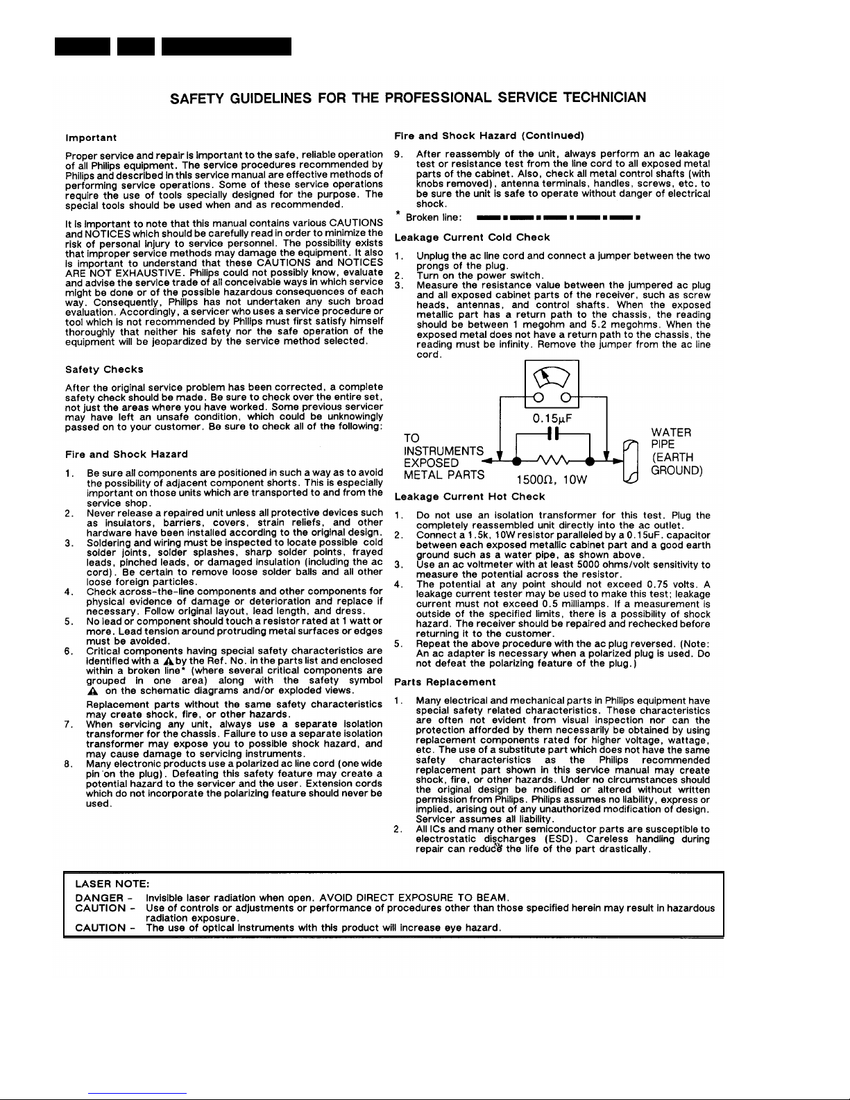
SHOCK, FIRE HAZARD SERVICE TEST:
CAUTION: After servicing this appliance and prior to returning to customer, measure the resistance between
either primary AC cord connector pins (with unit NOT connected to AC mains and its Power switch ON), and the
face or Front Panel of product and controls and chassis bottom,
Any resistance measurement less than 1 Megohms should cause unit to be repaired or corrected before AC
power is applied, and verified before return to user/customer.
Ref.UL Standard NO.1492.
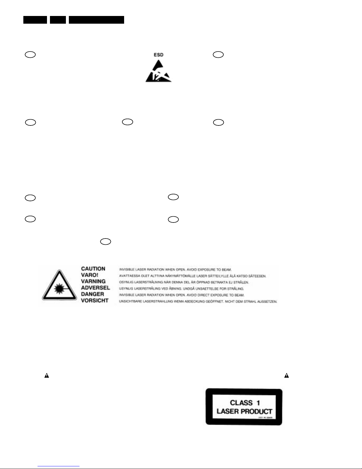
NOTE ON SAFETY:
Symbol
: Fire or electrical shock hazard. Only original parts should be used to replace any part with symbol
Any other component substitution(other than original type), may increase risk or fire or electrical shock hazard.
F
ATTENTION
Tous les IC et beaucoup d'autres semiconducteurs sont sensibles aux décharges
statiques (ESD).
Leur longévité pourrait être considérablement
écourtée par le fait qu'aucune précaution
n'est prise a leur manipulation.
Lors de réparations, s'assurer de bien être
relié au même potentiel que la masse de
l'appareil et enfiler le bracelet serti d'une
résistance de sécurité.
Veiller a ce que les composants ainsi que les
outils que l'on utilise soient également a ce
potentiel.
D
WARNUNG
Alle IC und viele andere Halbleiter sind
empfindlich gegen elektrostatische
Entladungen (ESD).
Unsorgfältige Behandlung bei der Reparatur
kann die Lebensdauer drastisch vermindern.
Sorgen sie dafür, das Sie im Reparaturfall
über ein Pulsarmband mit Widerstand mit
dem Massepotential des Gerätes verbunden
sind.
Halten Sie Bauteile und Hilfsmittel ebenfalls
auf diesem Potential.
NL
WAARSCHUWING
Alle IC's en vele andere halfgeleiders zijn
gevoelig voor elektrostatische ontladingen
(ESD).
Onzorgvuldig behandelen tijdens reparatie
kan de levensduur drastisch doen
verminderen.
Zorg ervoor dat u tijdens reparatie via een
polsband met weerstand verbonden bent met
hetzelfde potentiaal als de massa van het
apparaat.
Houd componenten en hulpmiddelen ook op
ditzelfde potentiaal.
I
AVVERTIMENTO
Tutti IC e parecchi semi-conduttori sono
sensibili alle scariche statiche (ESD).
La loro longevita potrebbe essere fortemente
ridatta in caso di non osservazione della piu
grande cauzione alla loro manipolazione.
Durante le riparazioni occorre quindi essere
collegato allo stesso potenziale che quello
della massa dell'apparecchio tramite un
braccialetto a resistenza.
Assicurarsi che i componenti e anche gli
utensili con quali si lavora siano anche a
questo potenziale.
All ICs and many other semi-conductors are
susceptible to electrostatic discharges (ESD).
Careless handling during repair can reduce
life drastically.
When repairing, make sure that you are
connected with the same potential as the
mass of the set via a wrist wrap with
resistance.
Keep components and tools also at this
potential.
GB
WARNING
GB
Safety regulations require that the set be restored to its original condition
and that parts which are identical with those specified be used.
NL
Veiligheidsbepalingen vereisen, dat het apparaat in zijn oorspronkelijke
toestand wordt terug gebracht en dat onderdelen, identiek aan de
gespecifieerde worden toegepast.
D
Bei jeder Reparatur sind die geltenden Sicherheitsvorschriften zu beachten.
Der Originalzustand des Gerats darf nicht verandert werden.
Fur Reparaturen sind Original-Ersatzteile zu verwenden.
I
Le norme di sicurezza esigono che l'apparecchio venga rimesso nelle
condizioni originali e che siano utilizzati pezzi di ricambiago idetici a quelli
specificati.
F
Les normes de sécurité exigent que l'appareil soit remis a l'état d'origine et
que soient utilisées les pièces de rechange identiques à celles spécifiées.
“Pour votre sécurité, ces documents
doivent être utilisés par des
spécialistes agrées, seuls habilités à
réparer votre appareil en panne.”
CL 96532086_021.eps
080999
Safety and Maintenance Instructions Warnings and Notes
GB 5CDR Mozart 2.
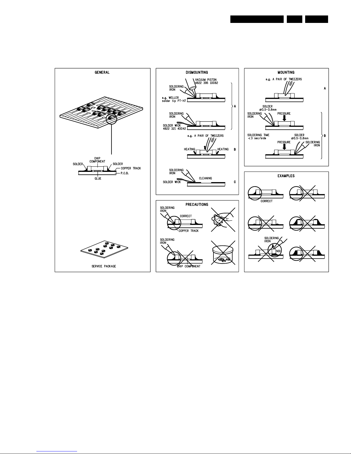
SERVICING HINTS
In the set, chip components have been applied. For disassembly and assembly check the figure below.
CL 96532086_022.eps
080999
Safety and Maintenance Instructions Warnings and Notes
GB 6 CDR Mozart2.
CL 96532086_023.eps
080999

Instructions for Use
GB 7CDR Mozart 3.
3. Instructions for Use
See Service Manual of concerned modelnumber in which the
instructions for use have been inserted. This chapter has not
been filled as this CDR Mozart Module is only a part of a
complete set.
4. Mechanical instructions
4.1 CD Recording Drive Mechanism
The CD (Recording) Drive Mechanism, Tray Loading
Mechanism and Front-end Board part of the module (also
called CD R/W BASIC ENGINE) can have 2 different
executions. One is called FREYA the other RACOON. As
information and repair activity about RACOON is not defined
yet, this part is not included in this Service Manual.
Notice that both Mechanisms can not be interchanged, so
RACOON has to be replaced by RACOON, FREYA by
FREYA. As both parts can only be repaired with the help of
CDR-ComPair, the ComPair tool will contain the instructions
for both mechanisms.
Mechanical instructions
GB 8 CDR Mozart4.
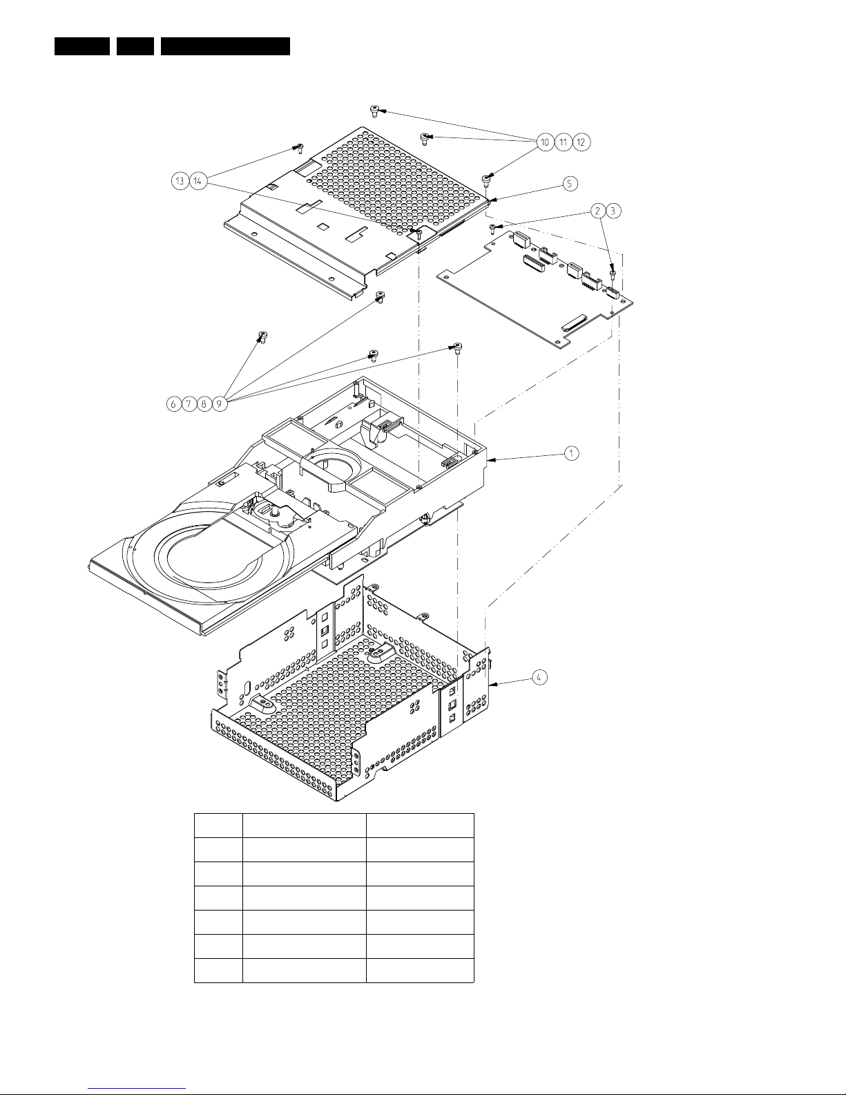
Exploded View CDR-Module
CL 16532046_001.eps
130701
1001
ITEM DESCRIPTION CODENUMBER
1 VAE 5020/01 LOADER 9305 025 52001
2-3,13-14 SCREW PLASTITE M2x6 2511 076 50002
4 SHIELDING BOTTOM 3103 301 45360
5 SHIELDING TOP 3103 301 45370
6-12 SCREW TAPTITE M3x6 2511 077 00039
1001 MOZART BOARD
Mechanical instructions
GB 9CDR Mozart 4.
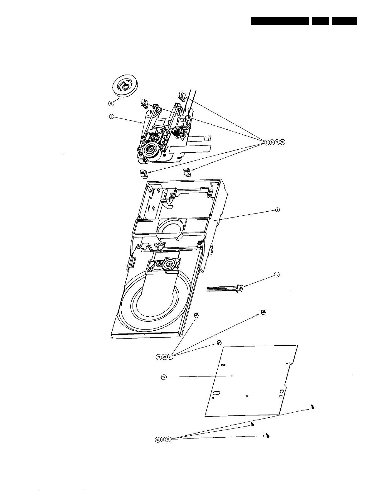
Exploded View VAE5020
EXPLODED VIEW VAE5020
CL 16532046_002.eps
101001
ITEM CODENUMBER DESCRIPTION
1 3139 197 60100 FREYA LOADER ASSY
4 9305 022 52001 VAM5020/01
7 3139 194 00790 SUSPENSION
8 3139 194 00790 SUSPENSION
9 3139 194 00790 SUSPENSION
10 3139 194 00790 SUSPENSION
12 3139 197 60060 CLAMPER
15 3139 198 00280 FREYA2 SERVO BOARD
Mechanical instructions
GB 10 CDR Mozart4.
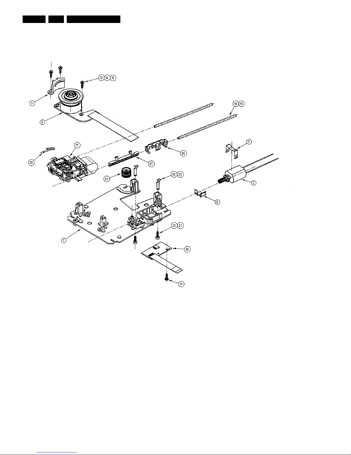
Exploded View VAM5020
EXPLODED VIEW VAM5020
CL 16532046_005.eps
101001
ITEM CODENUMBER DESCRIPTION
1 3139 197 50100 OUTSERT MOUNTING PLATE ASSY
3 3139 198 00200 SLEDGE MOTOR ASSY
5 3139 191 20380 THRUST SPRING
7 4822 402 61558 CLAMPING BRACKET
9 3139 198 00230 FREYA 2 MOTOR AND TURNTABLE
11 3139 194 00660 MOTOR CATCH
13 3139 190 40100 PLASTIC SCREW 2 X 7
14 3139 190 40100 PLASTIC SCREW 2 X 7
15 3139 190 40100 PLASTIC SCREW 2 X 7
17 9305 011 24252 OPU-24.25
18 3139 191 20370 SPINDLE
19 3139 191 20370 SPINDLE
25 3139 194 00700 COMBI WHEEL
26 3139 191 20400 RACK SPRING
27 3139 194 00770 RACK
28 3104 141 21830 THIRD BEARING SPRING
30 3139 198 00270 Board-FLEX ASSY FREYA
31 3139 190 40100 PLASTIC SCREW 2 X 7
Mechanical instructions
GB 11CDR Mozart 4.
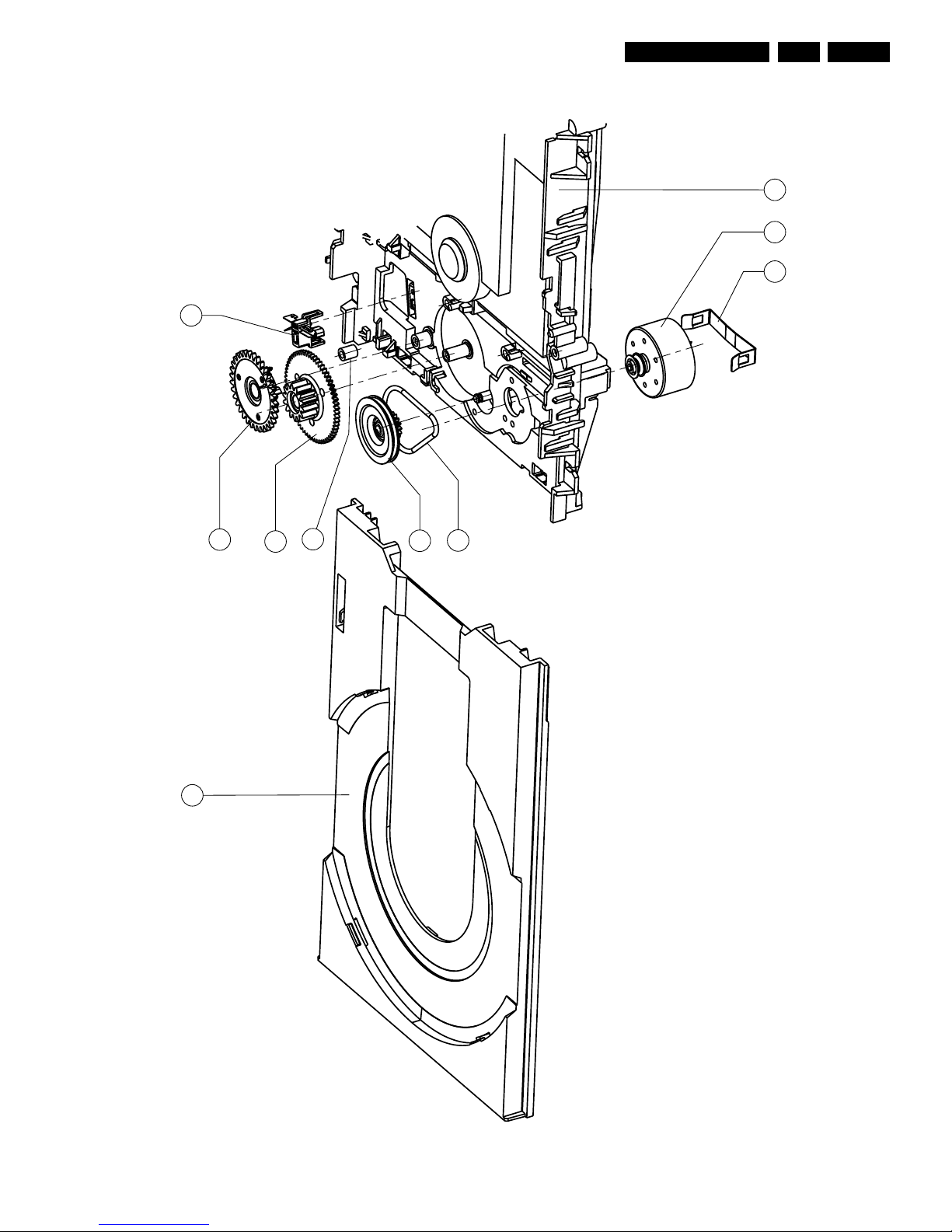
Exploded View Freya Loader
CL 16532046_003.eps
040701
11
09
06
08
10
05
04
16 12 13
04 4822 358 10266 BELT LOADER
05 PULLEY WHEEL
06 TRAY GEAR WHEEL
08 RACK GEAR WHEEL
09 3139 198 80010 SWITCH
10 4822 532 13097 TULE
11 3139 194 00800 TRAY BLACK
12 3139 197 50060 TRAY MOTOR ASSY
13 3139 194 00740 CHASSIS
16 MOTOR SPRING
Trouble Shooting
GB 12 CDR Mozart5.
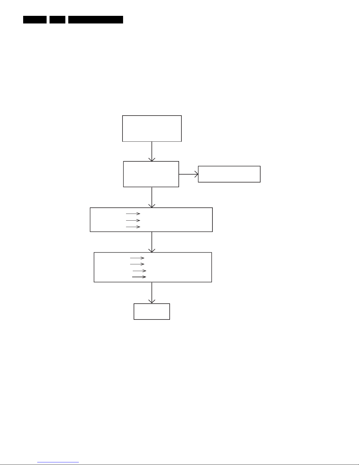
5. Trouble Shooting
Power Part Check
Switch On
Power Supply
+12V(+/-10%) testpoint 1
+5V(+/-10%) testpoint 2
+12V_MOT testpoint 3
+5V_BE testpoint 4
Check Power Supply Unit
Check Fuse 1211 and 1212
NOK
OK
OK
OK
OK
-12V testpoint 5
NOK
NOK
NOK
Check IC 7202, R3222 and D6203
+3V3 testpoint 6
+2V5 testpoint 7
Check Voltage Regulator 7208
Check Voltage Regulator 7209
Check Voltage Regulator 7201
+8VA testpoint 8
+5VA testpoint 9
-8VA testpoint 10
-5VA testpoint 11
NOK
NOK
NOK
NOK
Check IC 6204
Check IC 7200
Check IC 7200 and Diode 6202
Power Part
Power Part Check
USE MOZART MAIN BOARD CIRCUIT DIAGRAM 3 AND MOZART MAIN BOARD BOTTOM-AND TOP VIEW: TEST POINTS
CL 16532046_006.eps
101001
Trouble Shooting
GB 13CDR Mozart 5.
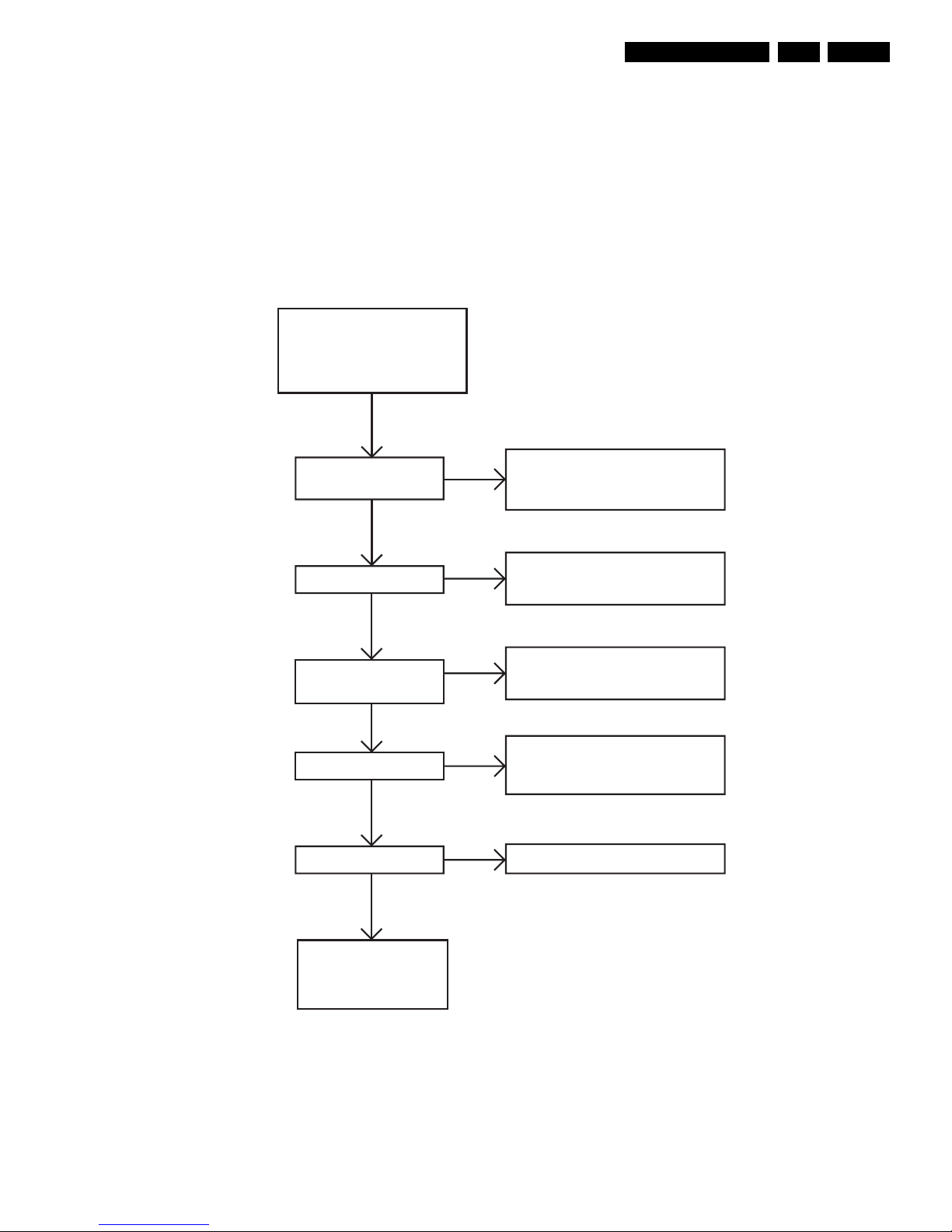
Power Part Check FREYA Servo
Board
Switch On
Power Supply
+12V testpoint 12
+3V3 testpoint 14
FS30V testpoint 15
= +27V
+5V testpoint 13
- Check Fuse 1543 and 1541
- Check D 6541, D6543
- Check Mozart Back-end board
- Check Fuse 1501
- Check T 7020
NOK
NOK
- Check D 6554
- Check L 5554
NOK
OK
OK
-8V testpoint 16
- Check D 6547
- Check L 5553
- Check T 7547
NOK
-5V testpoint 17
- Check IC 7556
NOK
OK
OK
OK
OK
Power Part
Freya mainboard
Power Part Check FREYA Servoboard
USE FREYA SERVOBOARD CIRCUIT DIAGRAM3 AND FREYA SERVOBOARD BOTTOM-AND TOP VIEW: TEST POINTS
CL 16532046_045.eps
101001
Trouble Shooting
GB 14 CDR Mozart5.
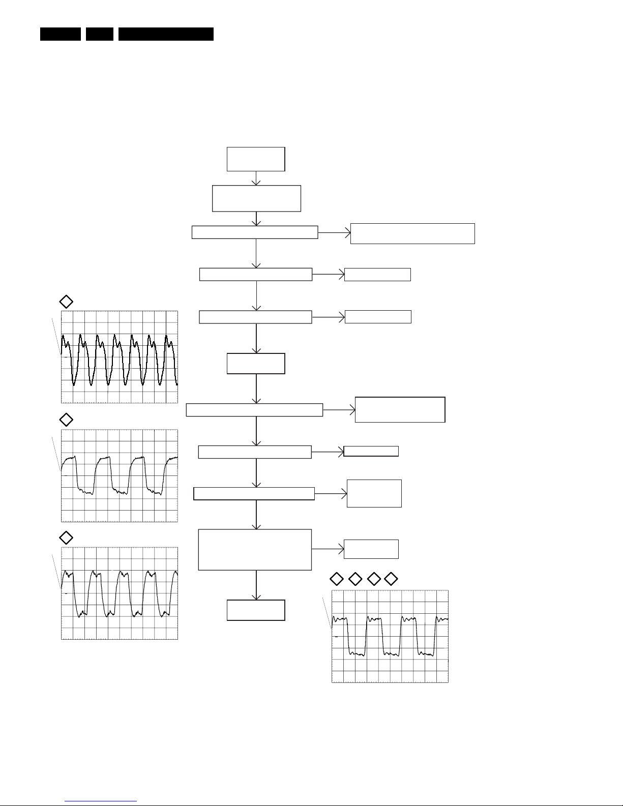
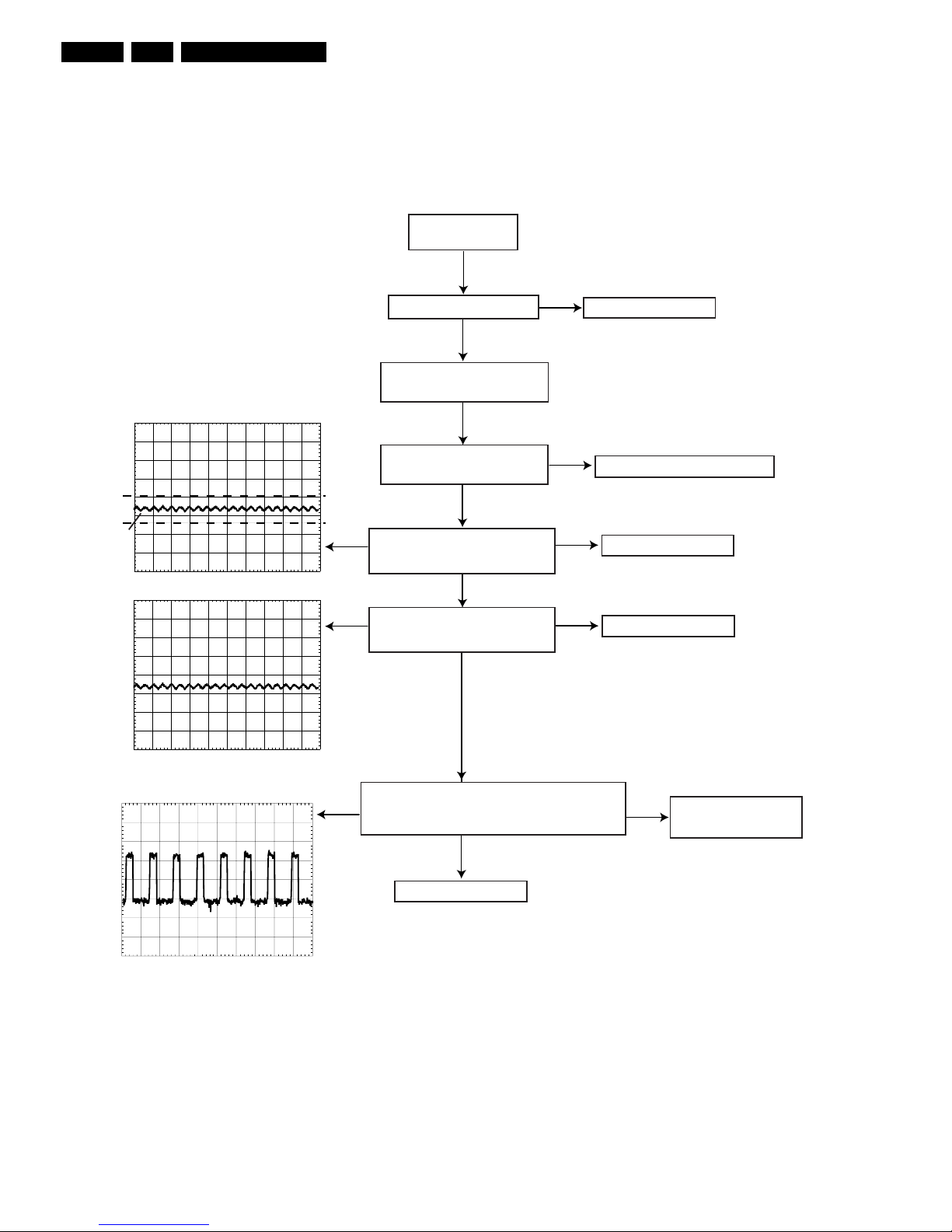
Reset & Clock Check
Switch on the
Power Supply
Power On Reset (+3V3) testpoint R1
OK
OK
OK
OK
OK
OK
OK
OK
NOK
Check IC7000
NOK
Check IC7000
Check IC7000
NOK
RST ADDA (+3V3) testpoint R2
RST FREYA (+3V3) testpoint R3
RESET Signals
OK
CLOCK Signals
OK
MAIN_CLK 33,8688MHz testpoint R4
NOK
Check X-tal 1005
Check D6002 and D6003
Check IC7000
NOK
Check IC7000
NOK
Check IC7004
SYS_CLK 16,9MHz testpoint R5
FREYA_CLK 8,5MHz testpoint R6
Check IC7012
Check R3019
NOK
Check IC7010
Check R3028
DAC_CLK 16,9MHz testpoint R7
ADC_CLK 16,9MHz testpoint R8
IO_CLK 16,9MHz testpoint R9
IO_CLK ABBA testpoint R10
RESET & CLOCK CHECK
USE MOZART MAIN BOARD CIRCUIT DIAGRAM 1 AND MOZART MAIN BOARD BOTTOM-AND TOP VIEW: TESTPOINTS
ch1
ch1: pkpk= 4.50 V
ch1: freq= 33.8MHz
CH1 1.00 V~ MTB20.0ns ch1+
1
ch1
ch1: pkpk= 3.34 V
ch1: freq= 16.9MHz
CH1 1.00 V~ MTB20.0ns ch1+
1
ch1
ch1: pkpk= 4.12 V
ch1: freq= 8.51MHz
CH1 1.00 V~ MTB50.0ns ch1+
1
ch1
ch1: pkpk= 3.50 V
ch1: freq= 16.9MHz
CH1 1.00 V~ MTB20.0ns ch1+
1
R4
R5
R6
R7
R8
R9
R10
Display uP generates
the Power On Reset
Check connection to Display board
CL 16532046_007.eps
101001
Trouble Shooting
GB 15CDR Mozart 5.
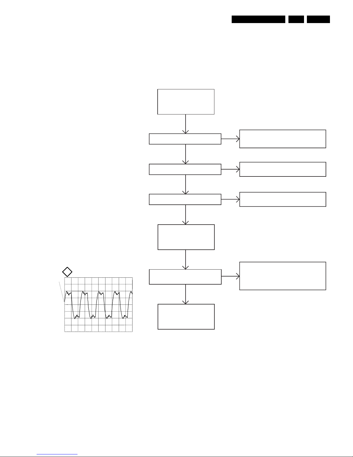
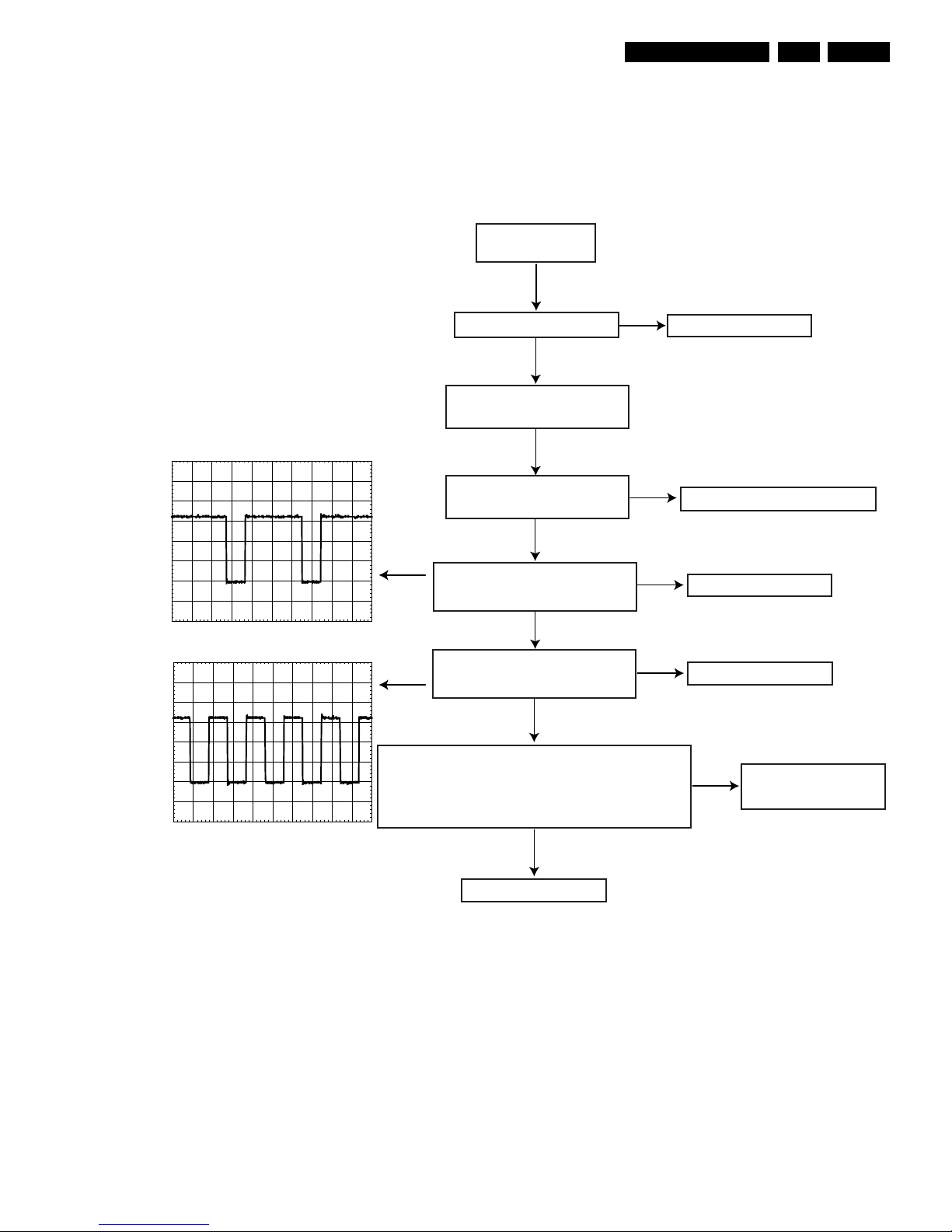
Reset & Clock Check FREYA Servo Board
Switch On
Power Supply
Check connection from CDR Freya
Servoboard connector 1000 to
connector 1201 on CDR Mozart mainboard
NOK
Check connection from CDR Freya
Servoboard connector 1000 to
connector 1201 on CDR Mozart mainboard
- Check IC 7019
- Check IC 7018
NOK
NOK
OK
OK
Reset and Clock Check FREYA Servoboard
USE FREYA SERVOBOARD CIRCUIT DIAGRAM1 AND 4 AND FREYA SERVOBOARD BOTTOM-AND TOP VIEW: TEST POINTS
+3V3 on testpoint R11
NRST-signal(+3V3) on testpoint R12
- Check T 7108
- Check D 6020 and D 6021
NOK
OK
RESET_N(low) on testpoint R13
SYSCLK = FREYA_CLK 8.5MHz
on testpoint R14
- Check T 7107
- Check R 3153
Reset part
OK
OK
Clock FREYA
OK
OK
ch1
ch1: pkpk= 4.12 V
ch1: freq= 8.51MHz
CH1 1.00 V~ MTB50.0ns ch1+
1
R14
CL 16532046_046.eps
101001
Trouble Shooting
GB 16 CDR Mozart5.
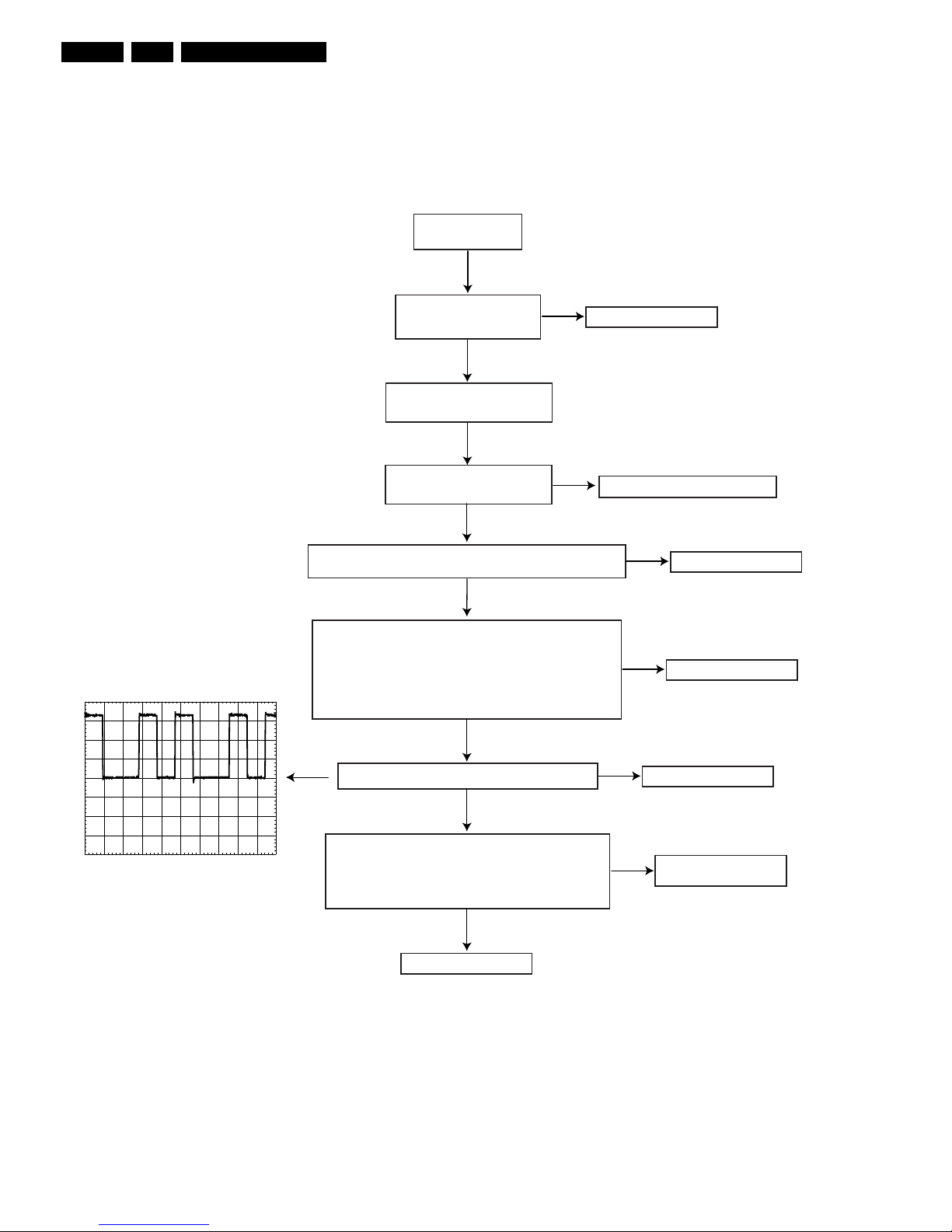
Servo Drivers Check (Focus Servo)
NOK
OK
OK
FOCUS SERVO OK
Switch on player
via ComPair mode
SERVO DRIVERS CHECK
USE FREYA2 CIRCUIT DIAGRAM 1 and 3 AND FREYA SERVO BOARD BOTTOM- AND TOP VIEW: TESTPOINTS
Execute "focus" tests
Check power part
Check reset and clock part
Check
S1V65
(=1V65) at
testpoint S9
NOK
Check R3002, R3065, C2054
OK
Check MACE 7019
OK
NOK
Check driver 7003
Check MACE 7019
Check VAM5020
OK
FOCUS SERVO OK
FOCUS SERVO
OK
NOK
Check
VFO
signal
on testpoint S16 (TP59,TP153)
Execute "focus off" test
Check MACE 7019
NOK
PM3392A
CH1:500mV= MTB2.00us
VFO
GND
PM3392A
CH1:500mV= MTB2.00us
VFO
GND
Moving between
1V3 and 2V
PM3392A
ch1: freq= 1.61 Hz
CH1:50.0mV= MTB 500ms
GND
FOC-/FOC+
CL 16532046_012.eps
101001
Check
VFO
signal
on testpoint S16 (TP59)
Execute "focus on" test
Check signal across
FOC+/FOC-
on testpoints S17 (TP57)
and S18 (TP58) when executing "focus on"
Trouble Shooting
GB 17CDR Mozart 5.
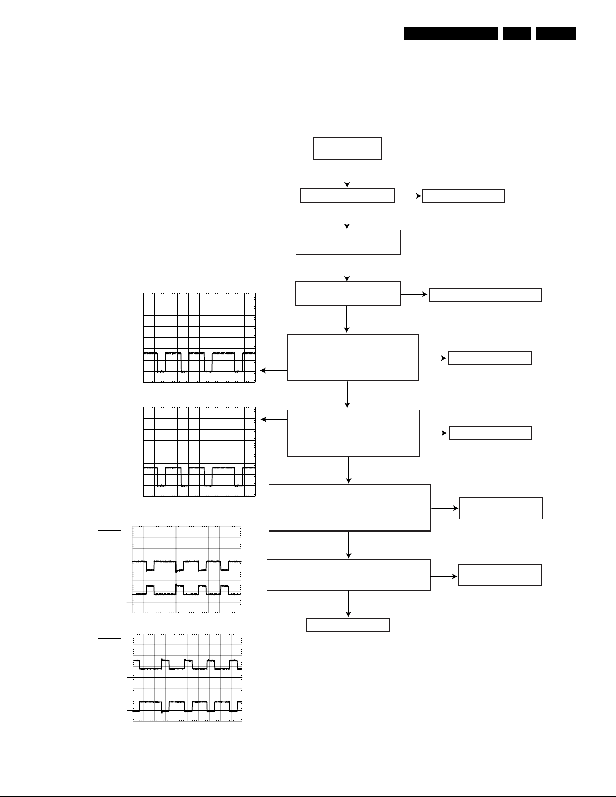
Servo Drivers Check (Radial Servo)
NOK
OK
OK
RADIAL SERVO OK
SERVO DRIVERS CHECK
USE FREYA2 CIRCUIT DIAGRAM 1 AND 3 AND FREYA SERVO BOARD BOTTOM- AND TOP VIEW: TESTPOINTS
Execute "radial control" tests
Check power part
Check reset and clock part
Check
S1V65
(=1V65) at
testpoint S9
NOK
Check R3002, R3065, C2054
OK
Check MACE 7019
OK
VRA
GND
Check
RAD+
signal on testpoint S14 (TP53):
+4V2 (going to 6V8 when executing "radial control on")
Check
RAD-
signal on testpoint S15 (TP56):
+0V65 (going to 4V3 when executing "radial control off")
NOK
OK
RADIAL SERVO OK
RADIAL SERVO
OK
Execute "radial control on" test
Check
VRA
signal on
testpoint S13 (TP152)
PM3392A
ch1:freq=532kHz
CH1:1.00 V= MTB 500ns
NOK
Execute "radial control off" test
Check
VRA
signal on
testpoint S13 (TP152)
PM3392A
ch1:freq=1.06MHz
CH1:1.00 V= MTB 500ns
VRA
GND
Check MACE 7019
NOK
Check driver 7003
Check MACE 7019
Check VAM5020
CL 16532046_013.eps
101001
Switch on player
via ComPair mode
Trouble Shooting
GB 18 CDR Mozart5.
Servo Drivers Check (Sledge Servo)
NOK
OK
OK
SLEDGE SERVO OK
SERVO DRIVERS CHECK
USE FREYA SERVO BOARD CIRCUIT DIAGRAM 1 AND 3 AND FREYA SERVO BOARD BOTTOM- AND TOP VIEW: TESTPOINTS
Execute "sledge inwards"
and "sledge outwards" tests
Check power part
Check reset and clock part
Check voltages testpoints S4, S5, S7, S8
(TP95, TP94, TP112, TP96) : +/- 1.6V
OK
NOK
Check VAM5020
NOK
Check opamp 7010
Check voltage testpoint S1 : if S1=0V then S3=0V
(TP 146) if S1=1V65 then 1V<S3<4V
if S1=3V3 then S3=5V
Check voltage testpoint S2 : if S2=0V then S6=0V
(TP 147) if S2=1V65 then 1V<S6<4V
if S2=3V3 then S6=5V
Check
S1V65
(=1V65) at
testpoint S9
OK
NOK
Check R3002, R3065, C2054
OK
Check
VSL
signal at testpoint S10 (TP151)
NOK
Check MACE 7019
OK
PM3392A
CH1:1.00 V= MTB 500ns
VSL
GND
Check
SL+
signal at testpoint S11 (TP54) :
+3V (going to 5V4 when executing "sledge outwards")
Check
SL-
signal at testpoint S12 (TP55) :
+5V4 (going to 3V4 when executing "sledge outwards")
NOK
Check driver 7003
Check MACE 7019
OK
SLEDGE SERVO OK
SLEDGE SERVO
CL 16532046_014.eps
101001
Switch on player
via ComPair mode
Trouble Shooting
GB 19CDR Mozart 5.
Servo Drivers Check (Tray Servo)
NOK
OK
OK
TRAY SERVO OK
SERVO DRIVERS CHECK
USE FREYA SERVO BOARD CIRCUIT DIAGRAM 1 AND 3 AND FREYA SERVO BOARD BOTTOM- AND TOP VIEW: TESTPOINTS
Execute "TRAY" tests
Check power part
Check reset and clock part
Check
S1V65
(=1V65) at
testpoint S9
NOK
Check R3002, R3065, C2054
OK
Check MACE 7019
Check signal
TRAYSW
at testpoint S23 (TP79) :
3V3 during commands open and close,
0V after completion
Check driver 7019
Check VAL5020
OK
TRAY SERVO OK
TRAY SERVO
OK
NOK
PM3392A
CH1:2.00 V= MTB 500us
TRAYOUT
GND
Execute "tray open" test
Check
Tray Out
signal on testpoint S19
(TP177) during command
Tray In
(testpoint S20) stays at 3V2
PM3392A
CH1:2.00 V= MTB 500us
TRAYIN
GND
Check MACE 7019
OK
NOK
Execute "tray close" test
Check
Tray In
signal on testpoint S20
(TP176) during tray command
Tray Out
(testpoint S19) stays at 3V2
Check
TR+
(testpoint S21;TP77),
TR-
(testpoint S22;TP78) :
PM3392A
CH1:5.00 V=
CH2:5.00 V= MTB 500us
GNDTR-
GNDTR+
TR+
TR-
NOK
OK
PM3392A
CH1:5.00 V=
CH2:5.00 V= MTB 500us
GNDTR-
GNDTR+
osc. a
osc. b
Check VAL5020
NOK
TR+
TR-
CL 16532046_015.eps
101001
Switch on player
via ComPair mode
- values without commands 4V2
- values during "tray open" command (osc. a)
- values during "tray close" command (osc. b)
 Loading...