

Page 1

Respironics V60 V entilator
User Manual
Page 2

For Technical Support and Customer Service, contact:
USA and Canada: 800-345-6443 or 724-387-4000
Respironics Europe, Africa, Middle East: +33-1-47-52-30-00
Respironics Asia Pacific: +852-3194-2280
Facsimile: +1-724-387-5012
USA
Respironics California, Inc.
2271 Cosmos Court
Carlsbad, CA 92011
Email and web addresses
service@philips.com
clinical@philips.com
www.philips.com\healthcare
Authorized European representative
Respironics Deutschland GmbH
Gewerbestrasse 17
D-82211 Herrsching
Germany
+49-8-15-29-30-60
© 2009 Respironics and its affiliates.
All rights reserved.
This work is protected under T itle 17 of the United States copyright code and is the sole property of Respironics.
No part of this document may be copied or otherwise reproduced, or stored in any electronic information
retrieval system, except as specifically permitted under United States copyright law, without the prior written
consent of Respironics.
Page 3

Table of contents
1. Warnings, cautions, and notes . . . . . . . . . . . . . . . . . . . . . . . . . . . . . . . 1-1
Definitions . . . . . . . . . . . . . . . . . . . . . . . . . . . . . . . . . . . . . . . . . . . . 1-1
General. . . . . . . . . . . . . . . . . . . . . . . . . . . . . . . . . . . . . . . . . . . . . . . 1-1
Preparing for ventilation . . . . . . . . . . . . . . . . . . . . . . . . . . . . . . . . . . . 1-3
Operation . . . . . . . . . . . . . . . . . . . . . . . . . . . . . . . . . . . . . . . . . . . . . 1-5
Alarms and messages. . . . . . . . . . . . . . . . . . . . . . . . . . . . . . . . . . . . . 1-5
Care and maintenance . . . . . . . . . . . . . . . . . . . . . . . . . . . . . . . . . . . . 1-5
First-time installation. . . . . . . . . . . . . . . . . . . . . . . . . . . . . . . . . . . . . 1-6
Communications interface . . . . . . . . . . . . . . . . . . . . . . . . . . . . . . . . . 1-7
Diagnostic mode . . . . . . . . . . . . . . . . . . . . . . . . . . . . . . . . . . . . . . . . 1-7
2. Symbols . . . . . . . . . . . . . . . . . . . . . . . . . . . . . . . . . . . . . . . . . . . . . . . 2-9
3. General information . . . . . . . . . . . . . . . . . . . . . . . . . . . . . . . . . . . . . . . 3-1
Intended use. . . . . . . . . . . . . . . . . . . . . . . . . . . . . . . . . . . . . . . . . . . 3-1
About CO
Potential side effects . . . . . . . . . . . . . . . . . . . . . . . . . . . . . . . . . . . . . 3-1
Contraindications. . . . . . . . . . . . . . . . . . . . . . . . . . . . . . . . . . . . . . . . 3-2
General description . . . . . . . . . . . . . . . . . . . . . . . . . . . . . . . . . . . . . . 3-2
Physical description. . . . . . . . . . . . . . . . . . . . . . . . . . . . . . . . . . . . . . 3-4
rebreathing . . . . . . . . . . . . . . . . . . . . . . . . . . . . . . . . . . . . 3-1
2
Patient circuits, masks/patient interfaces, and accessories . . . . . . . 3-4
Ventilator unit . . . . . . . . . . . . . . . . . . . . . . . . . . . . . . . . . . . . . . 3-6
Graphical user interface . . . . . . . . . . . . . . . . . . . . . . . . . . . . . . . 3-9
4. Principles of operation. . . . . . . . . . . . . . . . . . . . . . . . . . . . . . . . . . . . . 4-1
System operational overview . . . . . . . . . . . . . . . . . . . . . . . . . . . . . . . . 4-1
Pneumatic system operation . . . . . . . . . . . . . . . . . . . . . . . . . . . . . . . . 4-2
Breath delivery characteristics . . . . . . . . . . . . . . . . . . . . . . . . . . . . . . 4-2
Control variable . . . . . . . . . . . . . . . . . . . . . . . . . . . . . . . . . . . . . 4-2
Triggering, cycling, and leak adaptation . . . . . . . . . . . . . . . . . . . . 4-2
Baseline pressure . . . . . . . . . . . . . . . . . . . . . . . . . . . . . . . . . . . . 4-2
Pressure rise time . . . . . . . . . . . . . . . . . . . . . . . . . . . . . . . . . . . . 4-3
Negative pressures . . . . . . . . . . . . . . . . . . . . . . . . . . . . . . . . . . . 4-3
Oxygen concentration . . . . . . . . . . . . . . . . . . . . . . . . . . . . . . . . . 4-3
Auto-Trak Sensitivity . . . . . . . . . . . . . . . . . . . . . . . . . . . . . . . . . . . . . 4-3
Triggering . . . . . . . . . . . . . . . . . . . . . . . . . . . . . . . . . . . . . . . . . . 4-3
Cycling . . . . . . . . . . . . . . . . . . . . . . . . . . . . . . . . . . . . . . . . . . . 4-3
Leak adaptation . . . . . . . . . . . . . . . . . . . . . . . . . . . . . . . . . . . . . 4-5
Ventilation modes . . . . . . . . . . . . . . . . . . . . . . . . . . . . . . . . . . . . . . . 4-7
CPAP mode . . . . . . . . . . . . . . . . . . . . . . . . . . . . . . . . . . . . . . . . 4-8
PCV mode . . . . . . . . . . . . . . . . . . . . . . . . . . . . . . . . . . . . . . . . . 4-9
S/T mode . . . . . . . . . . . . . . . . . . . . . . . . . . . . . . . . . . . . . . . . . 4-10
AVAPS mode (optional) . . . . . . . . . . . . . . . . . . . . . . . . . . . . . . . 4-11
1047358 Rev A Respironics V60 Ventilator User Manual iii
Page 4

Table of contents
5. Preparing for ventilation . . . . . . . . . . . . . . . . . . . . . . . . . . . . . . . . . . . 5-1
Connecting external devices . . . . . . . . . . . . . . . . . . . . . . . . . . . . . . . . . 5-1
Connecting oxygen. . . . . . . . . . . . . . . . . . . . . . . . . . . . . . . . . . . . . . . . 5-1
Installing the patient circuit . . . . . . . . . . . . . . . . . . . . . . . . . . . . . . . . . 5-2
Connecting to AC power . . . . . . . . . . . . . . . . . . . . . . . . . . . . . . . . . . . . 5-4
About the optional backup battery. . . . . . . . . . . . . . . . . . . . . . . . . . . . . 5-4
Starting up the ventilator . . . . . . . . . . . . . . . . . . . . . . . . . . . . . . . . . . . 5-6
Shutting down the ventilator. . . . . . . . . . . . . . . . . . . . . . . . . . . . . . . . . 5-6
Navigating the graphical user interface . . . . . . . . . . . . . . . . . . . . . . . . . 5-7
Preoperational check . . . . . . . . . . . . . . . . . . . . . . . . . . . . . . . . . . . . . . 5-8
Required materials . . . . . . . . . . . . . . . . . . . . . . . . . . . . . . . . . . . . 5-8
Procedure . . . . . . . . . . . . . . . . . . . . . . . . . . . . . . . . . . . . . . . . . . 5-8
Troubleshooting . . . . . . . . . . . . . . . . . . . . . . . . . . . . . . . . . . . . . . 5-9
Alarm tests . . . . . . . . . . . . . . . . . . . . . . . . . . . . . . . . . . . . . . . . . . . . 5-10
Preparation . . . . . . . . . . . . . . . . . . . . . . . . . . . . . . . . . . . . . . . . 5-10
High Inspiratory Pressure . . . . . . . . . . . . . . . . . . . . . . . . . . . . . . . 5-10
Low Tidal Volume . . . . . . . . . . . . . . . . . . . . . . . . . . . . . . . . . . . . 5-10
Patient Disconnect . . . . . . . . . . . . . . . . . . . . . . . . . . . . . . . . . . . 5-11
Patient Circuit Occluded . . . . . . . . . . . . . . . . . . . . . . . . . . . . . . . 5-11
6. Operation . . . . . . . . . . . . . . . . . . . . . . . . . . . . . . . . . . . . . . . . . . . . . . 6-1
Changing the mode . . . . . . . . . . . . . . . . . . . . . . . . . . . . . . . . . . . . . . . 6-2
Changing control settings . . . . . . . . . . . . . . . . . . . . . . . . . . . . . . . . . . . 6-3
Making batch setting changes . . . . . . . . . . . . . . . . . . . . . . . . . . . . 6-3
Changing individual ventilator settings . . . . . . . . . . . . . . . . . . . . . . 6-4
Using the Ramp Time function . . . . . . . . . . . . . . . . . . . . . . . . . . . . . . . 6-5
Changing alarm settings. . . . . . . . . . . . . . . . . . . . . . . . . . . . . . . . . . . . 6-6
Selecting the mask and exhalation port . . . . . . . . . . . . . . . . . . . . . . . . . 6-7
Running the exhalation port test . . . . . . . . . . . . . . . . . . . . . . . . . . . . . 6-10
Procedure . . . . . . . . . . . . . . . . . . . . . . . . . . . . . . . . . . . . . . . . . 6-10
Troubleshooting . . . . . . . . . . . . . . . . . . . . . . . . . . . . . . . . . . . . . 6-11
Other functions: the Menu window . . . . . . . . . . . . . . . . . . . . . . . . . . . 6-11
Brightness . . . . . . . . . . . . . . . . . . . . . . . . . . . . . . . . . . . . . . . . . 6-11
Loudness . . . . . . . . . . . . . . . . . . . . . . . . . . . . . . . . . . . . . . . . . . 6-11
Mask/Port . . . . . . . . . . . . . . . . . . . . . . . . . . . . . . . . . . . . . . . . . 6-11
Vent Info (ventilator information) . . . . . . . . . . . . . . . . . . . . . . . . . 6-11
Screen Lock . . . . . . . . . . . . . . . . . . . . . . . . . . . . . . . . . . . . . . . . 6-12
Standby . . . . . . . . . . . . . . . . . . . . . . . . . . . . . . . . . . . . . . . . . . . . . . 6-12
Help function . . . . . . . . . . . . . . . . . . . . . . . . . . . . . . . . . . . . . . . . . . 6-14
Table of modes and control settings . . . . . . . . . . . . . . . . . . . . . . . . . . 6-15
7. Patient monitoring. . . . . . . . . . . . . . . . . . . . . . . . . . . . . . . . . . . . . . . . 7-1
Display conventions . . . . . . . . . . . . . . . . . . . . . . . . . . . . . . . . . . . . . . . 7-1
Table of monitored parameters . . . . . . . . . . . . . . . . . . . . . . . . . . . . . . . 7-2
Scaling the waveform axes . . . . . . . . . . . . . . . . . . . . . . . . . . . . . . . . . . 7-2
Freezing and unfreezing waveforms . . . . . . . . . . . . . . . . . . . . . . . . . . . . 7-3
iv Respironics V60 Ventilator User Manual 1047358 Rev A
Page 5

Table of contents
8. Alarms and messages . . . . . . . . . . . . . . . . . . . . . . . . . . . . . . . . . . . . . 8-1
Responding to alarms. . . . . . . . . . . . . . . . . . . . . . . . . . . . . . . . . . . . . 8-1
Setting alarm loudness. . . . . . . . . . . . . . . . . . . . . . . . . . . . . . . . . . . . 8-4
Silencing alarms . . . . . . . . . . . . . . . . . . . . . . . . . . . . . . . . . . . . . . . . 8-5
Resetting alarms . . . . . . . . . . . . . . . . . . . . . . . . . . . . . . . . . . . . . . . . 8-5
Manually resetting alarms . . . . . . . . . . . . . . . . . . . . . . . . . . . . . . 8-5
Clearing autoreset alarms from the Alarms list . . . . . . . . . . . . . . . . 8-5
Hiding/displaying alarm messages. . . . . . . . . . . . . . . . . . . . . . . . . . . . 8-6
Alarms and other messages. . . . . . . . . . . . . . . . . . . . . . . . . . . . . . . . . 8-6
9. Care and maintenance . . . . . . . . . . . . . . . . . . . . . . . . . . . . . . . . . . . . . 9-1
Decontamination . . . . . . . . . . . . . . . . . . . . . . . . . . . . . . . . . . . . . . . . 9-1
Ventilator exterior . . . . . . . . . . . . . . . . . . . . . . . . . . . . . . . . . . . . 9-1
Touchscreen . . . . . . . . . . . . . . . . . . . . . . . . . . . . . . . . . . . . . . . . 9-2
Bacteria filter, patient circuit, and other accessories . . . . . . . . . . . 9-2
Preventive maintenance . . . . . . . . . . . . . . . . . . . . . . . . . . . . . . . . . . . 9-3
Replacing the air inlet filter . . . . . . . . . . . . . . . . . . . . . . . . . . . . . 9-4
Cleaning or replacing the cooling fan filter . . . . . . . . . . . . . . . . . . 9-5
Removing and replacing the battery . . . . . . . . . . . . . . . . . . . . . . . 9-6
Disposal . . . . . . . . . . . . . . . . . . . . . . . . . . . . . . . . . . . . . . . . . . . . . . 9-6
Storage. . . . . . . . . . . . . . . . . . . . . . . . . . . . . . . . . . . . . . . . . . . . . . . 9-6
Repairs. . . . . . . . . . . . . . . . . . . . . . . . . . . . . . . . . . . . . . . . . . . . . . . 9-6
Repacking and shipping . . . . . . . . . . . . . . . . . . . . . . . . . . . . . . . . . . . 9-6
10. Technical specifications . . . . . . . . . . . . . . . . . . . . . . . . . . . . . . . . . . 10-1
Control settings . . . . . . . . . . . . . . . . . . . . . . . . . . . . . . . . . . . . . . . . 10-1
Patient data . . . . . . . . . . . . . . . . . . . . . . . . . . . . . . . . . . . . . . . . . . 10-2
Alarms . . . . . . . . . . . . . . . . . . . . . . . . . . . . . . . . . . . . . . . . . . . . . . 10-3
Menu window settings . . . . . . . . . . . . . . . . . . . . . . . . . . . . . . . . . . . 10-3
Operator-accessible diagnostic mode functions. . . . . . . . . . . . . . . . . . 10-4
Physical characteristics . . . . . . . . . . . . . . . . . . . . . . . . . . . . . . . . . . 10-4
Environmental specifications . . . . . . . . . . . . . . . . . . . . . . . . . . . . . . 10-5
Pneumatic specifications . . . . . . . . . . . . . . . . . . . . . . . . . . . . . . . . . 10-5
Electrical specifications . . . . . . . . . . . . . . . . . . . . . . . . . . . . . . . . . . 10-5
Other specifications. . . . . . . . . . . . . . . . . . . . . . . . . . . . . . . . . . . . . 10-6
A. First-time installation. . . . . . . . . . . . . . . . . . . . . . . . . . . . . . . . . . . . . . A-1
Unpacking and inspection . . . . . . . . . . . . . . . . . . . . . . . . . . . . . . . . . A-1
Mounting the ventilator . . . . . . . . . . . . . . . . . . . . . . . . . . . . . . . . . . . A-2
Installing the optional battery . . . . . . . . . . . . . . . . . . . . . . . . . . . . . . . A-3
Installing oxygen inlet connector and AC power cord (Outside the USA and Ja-
pan only). . . . . . . . . . . . . . . . . . . . . . . . . . . . . . . . . . . . . . . . . . . . A-6
Installing the oxygen manifold kit . . . . . . . . . . . . . . . . . . . . . . . . . . . . A-7
Configuration and screen calibration . . . . . . . . . . . . . . . . . . . . . . . . . . A-7
1047358 Rev A Respironics V60 Ventilator User Manual v
Page 6

Table of contents
B. Communications interface . . . . . . . . . . . . . . . . . . . . . . . . . . . . . . . . . . B-1
RS-232 serial and analog I/O port. . . . . . . . . . . . . . . . . . . . . . . . . . . . B-2
Pinout of connector . . . . . . . . . . . . . . . . . . . . . . . . . . . . . . . . . . . B-2
Communications protocol . . . . . . . . . . . . . . . . . . . . . . . . . . . . . . B-3
Commands and transmission conventions . . . . . . . . . . . . . . . . . . . B-3
Remote alarm port. . . . . . . . . . . . . . . . . . . . . . . . . . . . . . . . . . . . . . B-12
C. Warranty. . . . . . . . . . . . . . . . . . . . . . . . . . . . . . . . . . . . . . . . . . . . . . . C-1
One-year warranty . . . . . . . . . . . . . . . . . . . . . . . . . . . . . . . . . . . . . . . . C-1
Warranty limits . . . . . . . . . . . . . . . . . . . . . . . . . . . . . . . . . . . . . . . . . . C-1
D. Parts and accessories. . . . . . . . . . . . . . . . . . . . . . . . . . . . . . . . . . . . . D-1
Adult masks . . . . . . . . . . . . . . . . . . . . . . . . . . . . . . . . . . . . . . . . . . . D-1
Pediatric masks. . . . . . . . . . . . . . . . . . . . . . . . . . . . . . . . . . . . . . . . . D-3
Exhalation ports. . . . . . . . . . . . . . . . . . . . . . . . . . . . . . . . . . . . . . . . . D-3
Patient breathing circuits . . . . . . . . . . . . . . . . . . . . . . . . . . . . . . . . . . D-4
Bacteria filter . . . . . . . . . . . . . . . . . . . . . . . . . . . . . . . . . . . . . . . . . . D-4
Operator maintenance parts . . . . . . . . . . . . . . . . . . . . . . . . . . . . . . . . D-4
Other parts . . . . . . . . . . . . . . . . . . . . . . . . . . . . . . . . . . . . . . . . . . . . D-5
E. Regulatory compliance . . . . . . . . . . . . . . . . . . . . . . . . . . . . . . . . . . . . E-1
Electromagnetic compatibility (EMC). . . . . . . . . . . . . . . . . . . . . . . . . . . E-1
Safety. . . . . . . . . . . . . . . . . . . . . . . . . . . . . . . . . . . . . . . . . . . . . . . . . E-1
F. Diagnostic mode . . . . . . . . . . . . . . . . . . . . . . . . . . . . . . . . . . . . . . . . . F-1
Entering the diagnostic mode . . . . . . . . . . . . . . . . . . . . . . . . . . . . . . . . F-1
System settings. . . . . . . . . . . . . . . . . . . . . . . . . . . . . . . . . . . . . . . . . . F-3
Language . . . . . . . . . . . . . . . . . . . . . . . . . . . . . . . . . . . . . . . . . . . F-4
Date/Time . . . . . . . . . . . . . . . . . . . . . . . . . . . . . . . . . . . . . . . . . . F-6
Pressure Units . . . . . . . . . . . . . . . . . . . . . . . . . . . . . . . . . . . . . . . F-7
Restore Default Settings . . . . . . . . . . . . . . . . . . . . . . . . . . . . . . . . F-8
Software Options . . . . . . . . . . . . . . . . . . . . . . . . . . . . . . . . . . . . . F-9
Baud Rate . . . . . . . . . . . . . . . . . . . . . . . . . . . . . . . . . . . . . . . . . F-10
Service. . . . . . . . . . . . . . . . . . . . . . . . . . . . . . . . . . . . . . . . . . . . . . . F-11
Significant Event Log . . . . . . . . . . . . . . . . . . . . . . . . . . . . . . . . . F-11
Touchscreen calibration . . . . . . . . . . . . . . . . . . . . . . . . . . . . . . . . . . . F-13
Exiting the diagnostic mode . . . . . . . . . . . . . . . . . . . . . . . . . . . . . . . . F-13
Glossary . . . . . . . . . . . . . . . . . . . . . . . . . . . . . . . . . . . . . . . . . . Glossary-1
Index . . . . . . . . . . . . . . . . . . . . . . . . . . . . . . . . . . . . . . . . . . . . . . Index-1
vi Respironics V60 Ventilator User Manual 1047358 Rev A
Page 7

Chapter 1. Warnings, cautions, and notes
Before using the Respironics V60 Ventilator on a patient, familiarize yourself
with this user manual, particularly the safety considerations listed. Be aware,
however, that this manual is a reference only. It is not intended to supersede
your institution’s protocol regarding the safe use of assisted ventilation.
Definitions WARNING: Alerts the user to the possibility of injury, death, or other serious adverse
reactions associated with the use or misuse of the device.
CAUTION: Alerts the user to the possibility of a problem with the device
associated with its use or misuse, such as device malfunction, device
failure, damage to the device, or damage to other property.
NOTE: Emphasizes information of particular importance.
General WARNING: An alternative means of ventilation shall be available whenever the
ventilator is in use. If a fault is detected in the ventilator, disconnect the
patient from it and immediately start ventilation with such a device. The
ventilator must be removed from clinical use and serviced by Respironicsauthorized service personnel.
WARNING: Use the Respironics V60 Ventilator on spontaneously breathing patients
only. It is an assist ventilator and is intended to augment the ventilation of
a spontaneously breathing patient. It is not intended to provide the total
ventilatory requirements of the patient.
WARNING: We do not recommend you use the Respironics V60 Ventilator on patients
who require ventilation at predetermined tidal volumes. The ventilator
provides continuous positive airway pressure (CPAP) and positive
pressure ventilation (S/T, PCV, and AVAPS) and is indicated for assisted
ventilation only. These modes do not provide ventilation with guaranteed
tidal volume delivery.
WARNING: We do not recommend you use AVAPS on patients who require rapid and
frequent IPAP adjustments to maintain a consistent tidal volume. AV APS, a
volume targeted mode, changes the IPAP setting in order to achieve the
target tidal volume. During AVAPS setup, there may be a period of time
before the target tidal volume is achieved. AVAPS is ideal for more
stabilized patients.
1047358 Rev A Respironics V60 Ventilator User Manual 1-1
Page 8

Chapter 1
Warnings, cautions, and notes
WARNING: To reduce the risk of CO2 rebreathing, make sure EPAP pressures and
exhalation times are sufficient to clear all exhaled gas through the
exhalation port. In noninvasive ventilation continuous air flow through the
port flushes exhaled gases from the circuit. The ability to completely
exhaust exhaled gas from the circuit depends on the EPAP setting and I:E
ratio. Higher tidal volumes further increase the volume of CO
rebreathed
2
by the patient.
WARNING: To reduce the risk of CO
rebreathing, monitor the patient for changes in
2
respiratory status at the start of ventilation and with each change in
ventilator settings, circuit configuration, or patient condition. Pay
attention to ventilator alarms that warn of increased CO
rebreathing risk.
2
WARNING: Be aware of the possibility of contamination from patient exhalate being
exhausted into the room through the exhalation port.
WARNING: To ensure accuracy of oxygen administration and to monitor for the
presence of contamination (incorrect gas connected), use an external
oxygen monitor to verify the oxygen concentration in the delivered gas.
WARNING: To reduce the risk of fire, use the ventilator in well-ventilated areas away
from flammable anesthetics. Do not use in a hyperbaric chamber or other
similarly oxygen-enriched environments. Do not use near an open flame.
WARNING: To reduce the risk of electric shock from liquid entering the device, do
not put a container filled with a liquid on the ventilator.
WARNING: To reduce patient risk of hypoxemia, keep free-flowing oxygen away from
air inlet of ventilator.
WARNING: The nurse call/remote alarm should be considered a backup to the
ventilator’s primary alarm system.
WARNING: To ensure that the alarm will be heard, make sure the alarm loudness is
adequate and avoid blocking the alarm speakers beneath the ventilator.
CAUTION: Federal law (USA) restricts this device to sale by or on the order of a
physician.
CAUTION: The Respironics V60 Ventilator is designed to operate in the
temperature range of 5 to 40 ºC (41 to 104 ºF). To minimize the risk
of overheating the device, do not operate adjacent to heaters or other
heat sources.
NOTE: The displays shown in this manual may not exactly match what you
see on your own ventilator.
NOTE: Pressures are indicated on the ventilator in cmH
O. Millibars and
2
hectopascals (hPa) are used by some institutions instead. Since
1 millibar equals 1 hPa, which equals 1.016 cmH
O, the units may
2
be used interchangeably.
NOTE: The ventilator is not intended for use as an ambulance transport
ventilator or as an Automatic Transport Ventilator as described by the
American Hospital Association and referenced by the FDA. It is
intended to allow the patient to be transported within the hospital
setting using a cart to move the ventilator.
NOTE: When attachments or other components or subassemblies are added
to the ventilator breathing system, the pressure gradient across the
ventilator breathing system, measured with respect to the ventilator
outlet, may increase.
1-2 Respironics V60 Ventilator User Manual 1047358 Rev A
Page 9

Chapter 1
Warnings, cautions, and notes
NOTE: To ensure the correct performance of the ventilator and the accuracy
of patient data, we recommend you use only Respironics-approved
accessories with the ventilator. See Appendix D, “Parts and
accessories”.
NOTE: This Respironics V60 Ventilator and its recommended accessories
that have patient contact are free of latex.
NOTE: If an alarm persists for no apparent reason, discontinue ventilator use
and contact Respironics.
NOTE: If you detect any unexplained changes in the performance or visual
displays of the ventilator, discontinue ventilator use and contact
Respironics.
NOTE: The Respironics V60 Ventilator does not support automatic record
keeping.
Preparing for
ventilation
WARNING: Connect the ventilator to an appropriate medical-grade oxygen source
only. The source must be able to deliver 100% oxygen regulated to 276
to 600 kPa (40 to 87 psig).
WARNING: To reduce the risk of hypoxia, connect only oxygen to the high-pressure
connector at the rear of the ventilator.
WARNING: To reduce the risk of fire, do not use a high-pressure oxygen hose that is
worn or contaminated with combustible materials like grease or oil.
WARNING: Always check the status of the oxygen cylinders before using the
ventilator during transport.
WARNING: To prevent possible asphyxia and to reduce the risk of CO
take these precautions with respect to mask and exhalation port use:
WARNING: Use only a mask with an exhalation port or a nasal mask for noninvasive
ventilation.
WARNING: Do not occlude the exhalation port.
WARNING: Turn on the ventilator and verify that the port is operational before
application. Pressurized gas from the ventilator should cause a
continuous flow of air to exhaust from the leak port, flushing exhaled gas
from the circuit.
WARNING: Never leave the mask on the patient while the ventilator is not operating.
When the ventilator is not operating, the exhalation port does not allow
sufficient exhaust to eliminate CO
rebreathing may occur.
WARNING: To ensure normal air circulation and exchange, do not cover or block the
ports on the ventilator or ventilator circuit. Do not block the air inlet panel
on the right side of the ventilator.
WARNING: To prevent possible patient injury and possible water damage to the
ventilator, make sure the humidifier is set to appropriate temperature and
humidification settings.
from the circuit. Substantial CO
2
rebreathing,
2
2
1047358 Rev A Respironics V60 Ventilator User Manual
1-3
Page 10

Chapter 1
Warnings, cautions, and notes
WARNING: To prevent the possibility of inadequate humidification, pay close
attention to the humidifier’s functioning when operating the ventilator at
an ambient temperature > 30 ºC (86 ºF). The ventilator warms the air
delivered to the patient above ambient temperature, which may impair the
humidifier’s performance.
WARNING: To reduce the risk that the patient will aspirate condensed water from the
breathing circuit, position any humidifier lower than both the ventilator
and the patient.
WARNING: To prevent possible patient injury and equipment damage, do not turn the
humidifier on until the gas flow has started and is regulated. Starting the
heater or leaving it on without gas flow for prolonged periods may result
in heat build-up, causing a bolus of hot air to be delivered to the patient.
Circuit tubing may melt under these conditions. Turn the heater power
switch off before stopping gas flow.
WARNING: To reduce the risk of fire, use only patient circuits intended for use in
oxygen-enriched environments. Do not use antistatic or electrically
conductive tubing.
WARNING: To prevent patient or ventilator contamination, we recommend you use a
Respironics-approved main flow bacteria filter on the patient gas outlet
port. Filters not approved by Respironics may degrade system
performance.
WARNING: To reduce the risk of bacterial contamination or damage, handle bacteria
filters with care.
WARNING: Any additional accessories in the patient circuit may substantially
increase flow resistance and impair ventilation.
WARNING: To reduce the risk of strangulation from patient tubing, use a tubing
support arm and secure the proximal pressure line with clips.
WARNING: To reduce the risk of electric shock, connect the ventilator to an AC
supply mains with protective earth only.
WARNING: Do not use extension cords, adapters, or power cords with the ventilator
that are not approved by Respironics.
WARNING: To prevent unintentional disconnection of the power cord, always use the
correct, Respironics-supplied power cord and lock it into place with the
power cord retainer before you switch the ventilator on. The retainer is
designed to hold the connector end of the Respironics-supplied cord
securely in place.
WARNING: To reduce the risk of electric shock, regularly inspect the AC power cord
and verify that it is not frayed or cracked.
WARNING: To reduce the risk of strangulation, route the power cord to avoid
entanglement.
WARNING: To reduce the risk of power failure, pay close attention to the battery’s
charge level. The battery’s operation time is approximate and is affected
by ventilator settings, discharge and recharge cycles, battery age, and
ambient temperature. Battery charge is reduced at low ambient
temperatures or in situations where the alarm is continuously sounding.
1-4 Respironics V60 Ventilator User Manual 1047358 Rev A
Page 11

Chapter 1
Warnings, cautions, and notes
WARNING: To ensure the ventilator’s safe operation, always run the full
preoperational check described in “Preoperational check” on page 5-8
before using the ventilator on a patient. If the ventilator fails any tests,
remove it from clinical use immediately. Do not use the ventilator until
necessary repairs are completed and all tests have passed.
WARNING: To prevent possible patient injury, disconnect the patient from the
ventilator before running the preoperational check. Make sure another
source of ventilatory support is available.
WARNING: To prevent possible patient injury due to nonannunciating alarms, verify
the operation of any remote alarm device before use.
WARNING: To prevent possible patient injury, always return alarm settings to
hospital-standard values after the preoperational check.
CAUTION: To prevent possible damage to the ventilator, ensure that the
connection to the oxygen supply is clean and unlubricated, and that
there is no water in the oxygen supply gas.
CAUTION: For 120 V equipment, grounding reliability can only be achieved
when it is connected to an equivalent receptacle marked “hospital
only” or “hospital grade.”
Operation WARNING: To prevent possible patient injury, avoid setting alarm limits to extreme
values, which can render the alarm system useless.
Alarms and messages WARNING: If AC power fails and the backup battery is not installed or is depleted, an
audible and visual alarm annunciates for at least 2 minutes. Immediately
discontinue ventilator use and secure an alternative means of ventilation.
As in most ventilators with passive exhalation ports, when power is lost,
sufficient air is not provided through the circuit and exhaled air may be
rebreathed.
Care and
maintenance
WARNING: To reduce the risk of electric shock, power down the ventilator and
disconnect it from AC power before cleaning or servicing it.
WARNING: To prevent patient or ventilator contamination, inspect and replace the
main flow bacteria filter between patients and at regular intervals (or as
stated by the manufacturer).
WARNING: To prevent possible patient injury, inspect and verify the proper operation
of the exhalation port regularly during use.
WARNING: To reduce the risk of fire, explosion, leakage, or other hazard, take these
precautions with respect to the battery:
1047358 Rev A Respironics V60 Ventilator User Manual
1-5
Page 12

Chapter 1
Warnings, cautions, and notes
- Do not attempt to disassemble, open, drop, crush, bend or deform,
insert foreign objects into, puncture, or shred the battery pack; modify
or remanufacture it; immerse or expose it to water or other liquids;
expose it to fire, excessive heat (including soldering irons); or put it in
a microwave oven.
- Replace the battery only with another battery specified by the
manufacturer.
- Follow all instructions for proper use of the battery.
- Do not short-circuit the battery or allow metallic or conductive objects
to contact the battery connector housing.
- Use the battery with the Respironics V60 Ventilator only.
CAUTION: Do not attempt to sterilize or autoclave the ventilator.
CAUTION: To prevent possible damage to the ventilator, use only those cleaning
agents listed in this manual.
CAUTION: To prevent possible damage to the touchscreen, take care when
cleaning it. Do not drip water and/or soap solution. After cleaning and
rinsing, remove all moisture with a dry, soft cloth. Never clean the
touchscreen with an abrasive brush or device, since this will cause
irreparable damage.
CAUTION: To avoid introducing foreign matter into the ventilator and to ensure
proper system performance, change the air inlet filter at regular
intervals (or as stipulated by your institution).
CAUTION: T o ensure proper system performance, use a Respironics-approved air
inlet filter.
CAUTION: Because some environments cause a quicker collection of lint and
dust than others, inspect the filters more often when needed. The air
inlet filter should be replaced; the cooling fan filter should be
cleaned.
CAUTION: To prevent possible damage to the ventilator, always ship it with the
original packing material. If the original material is not available,
contact Respironics to order replacements.
First-time installation WARNING: Never attempt to disconnect or connect the battery during operation.
CAUTION: To prevent possible damage to the ventilator, always secure it to its
stand or securely place it on a flat, stable surface that is free of dirt
and debris. Do not use the ventilator adjacent to, or stack it with,
other equipment.
1-6 Respironics V60 Ventilator User Manual 1047358 Rev A
Page 13

Chapter 1
Warnings, cautions, and notes
Communications
interface
WARNING: Connect to the ventilator only items that are specified as part of or
compatible with the ventilator system. Additional equipment connected to
medical electrical equipment must comply with the respective IEC or ISO
standards. Furthermore, all configurations shall comply with the
requirements for medical electrical systems (see IEC 60601-1-1 or
clause 16 of edition 3 of IEC 60601-1, respectively). Anybody connecting
additional equipment to medical electrical equipment configures a
medical system and is therefore responsible for ensuring that the system
complies with the requirements for medical electrical systems. Also be
aware that local laws may take priority over the above mentioned
requirements. If in doubt, consult Respironics.
WARNING: It is the responsibility of the end user to validate the compatibility and use
of information transmitted from the ventilator to the device to be
connected to the ventilator.
WARNING: The data provided through the communications interface is for reference
only. Decisions for patient care should be based on the clinician’s
observations of the patient.
WARNING: To prevent possible patient injury due to nonannunciating alarms, verify
the operation of any remote alarm device before use.
WARNING: To ensure the functionality of the remote alarm, connect only Respironics-
approved cables to the remote alarm port.
CAUTION: The remote alarm port is intended to connect only to an SELV (safety
extra-low voltage and ungrounded system with basic insulation to
ground), in accordance with IEC 60601-1. To prevent damage to the
remote alarm, make sure the signal input does not exceed the
maximum rating of 24 VAC or 36 VDC at 500 mA with a minimum
current of 1 mA.
Diagnostic mode WARNING: To prevent possible patient injury , do not enter the diagnostic mode while
a patient is connected to the ventilator. Verify that the patient is
disconnected before proceeding.
1047358 Rev A Respironics V60 Ventilator User Manual
1-7
Page 14

Chapter 1
Warnings, cautions, and notes
(This page is intentionally blank.)
1-8 Respironics V60 Ventilator User Manual 1047358 Rev A
Page 15
Chapter 2. Symbols
Refer to these tables to interpret symbols used on the ventilator labels and
packaging and on the ventilator screen. To interpret symbols pertaining to
accessories, refer to their instructions for use.
.
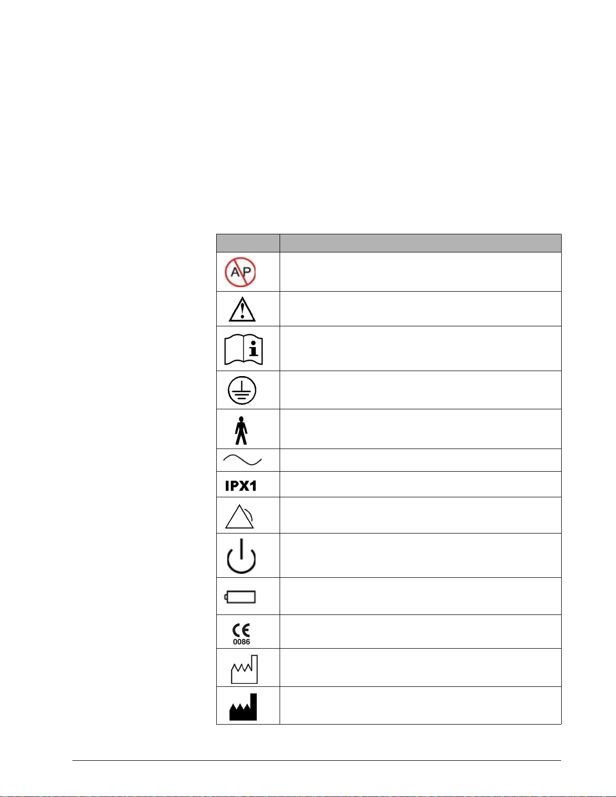
Table 2-1: Symbols used on ventilator labels and packaging
Symbol Description
Warning: Risk of explosion. Do not use in the presence of flammable anesthetics.
Attention, consult the accompanying documents.
Read the user manual before using the ventilator.
Protective earth (ground)
T ype B applied part, wh ich is equi pment that provid es a particular deg ree
of protection against electric shock, particularly in regard to allowable
leakage current and of the protective earth connection
Requires alternating current (AC)
Degree of fluid ingress protection provided by the enclosure (drip-proof)
Alarm and remote alarm
Two states of control: ON and Shutdown
Battery
European Conformity
Date of manufacture
Manufacturer
1047358 Rev A Respironics V60 Ventilator User Manual 2-9
Page 16
Chapter 2
(On power cord)
Symbols
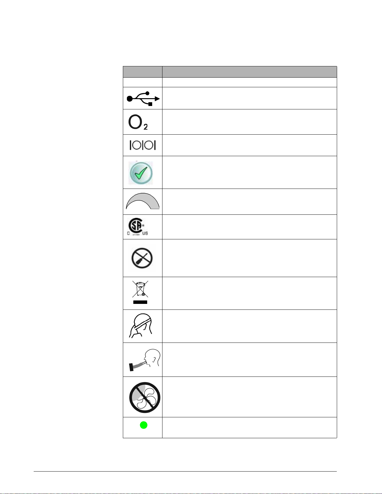
Table 2-1: Symbols used on ventilator labels and packaging (continued)
Symbol Description
RS-232 RS-232 serial input/output
USB port
Oxygen
Ethernet connection
Accept button on the navigation ring
Adjustment direction on the navigation ring
Canadian Standards Association approval
Do not disassemble. Refer to Respironics-authorized service personnel.
Product must be disposed of in accordance with the WEEE directive.
Noninvasive ventilation (patient with mask)
Invasive ventilation (intubated patient)
Do not block the cooling fan Inlet (at the rear of the ventilator).
Hospital-grade
2-10 Respironics V60 Ventilator User Manual 1047358 Rev A
Page 17
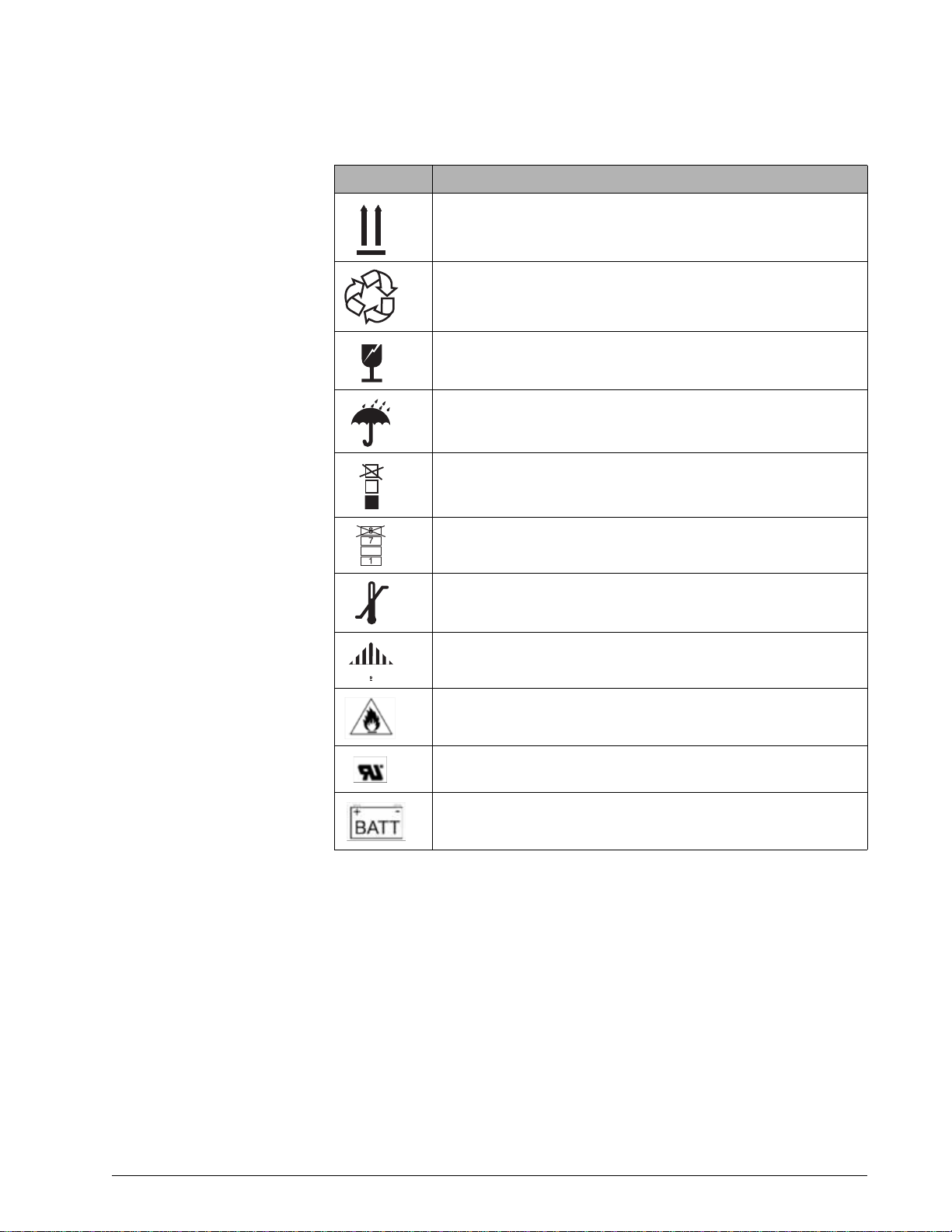
Table 2-1: Symbols used on ventilator labels and packaging (continued)
3
50C
20C
-
Symbol Description
This side up
Recycle
Fragile
Keep dry
Do not stack > 3 high
Chapter 2
Symbols
Do not stack > 7 high
Limit temperature to between -20 and 50 ºC (-4 and 122 ºF)
Hazmat class 9
Fire hazard
uR UL recognition symbol
Battery option
1047358 Rev A Respironics V60 Ventilator User Manual 2-11
Page 18
Chapter 2
Symbols
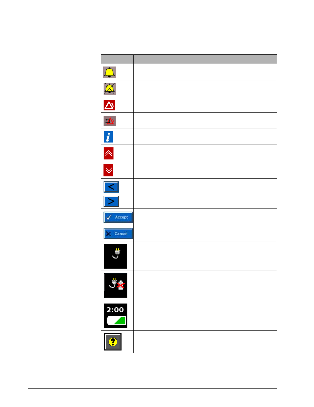
Table 2-2: Symbols used on graphical user interface
Symbol Description
Alarm (audible)
Alarm is silenced
Alarm
Alarm reset
Informational message
Alarm message is displayed. Touch to hide alarm messages.
Alarm message is hidden. Touch to display alarm messages.
Increase and decrease (adjustment arrow) buttons. Adjusts a setting or
selects a value.
Accept button. Accepts set values.
Cancel button. Cancels set values.
Ventilator is powered by AC power and the optional battery is installed.
Ventilator is powered by AC power and the optional battery is not installed.
Ventilator is powered by the battery. This symbol shows the approximate
battery time remaining in hours and minutes, and it shows the capacity
graphically.
Help button. Touch to display onscreen help information.
2-12 Respironics V60 Ventilator User Manual 1047358 Rev A
Page 19
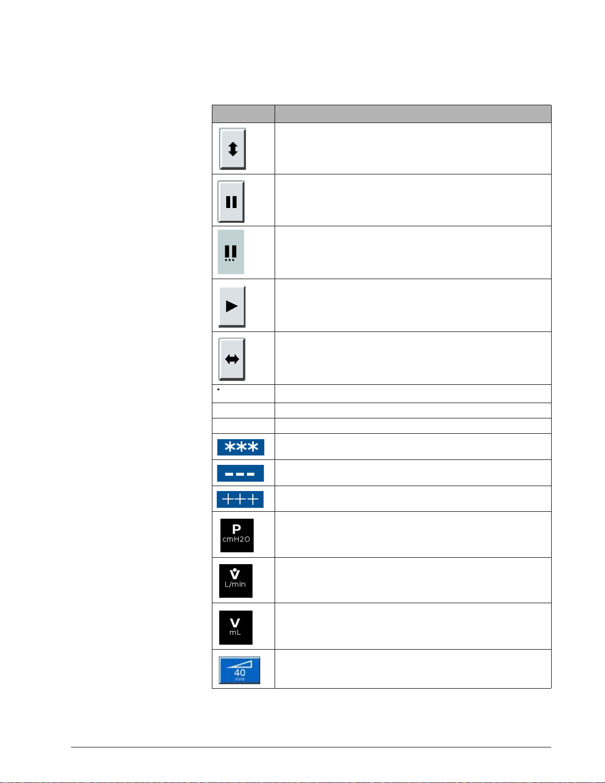
Table 2-2: Symbols used on graphical user interface (continued)
Symbol Description
Vertical autoscale button. Autoscales the Y axis of the graphs to fit the
data currently displayed.
Pause button. Freezes waveforms in the Waveform window.
Pause in progress
Resume button. Resumes all waveform graphs from a paused state.
Chapter 2
Symbols
V
E
V
T
T
I/TTOT
Time base adjust button. Rescales the X axis of the graph display data at
3, 6, 12, and 24 second increments.
Estimated minute ventilation
Estimated exhaled tidal volume
Duty cycle. Inspiratory time divided by total cycle time.
No valid data to display
Data is under range
Data is over range
Pressure, centimeters of water
Flow, liters per minute. BTPS compensated.
Volume, milliliters
User-set Ramp Time. Ramp graphic fills in as Ramp Time progresses.
1047358 Rev A Respironics V60 Ventilator User Manual 2-13
Page 20
Chapter 2
Symbols
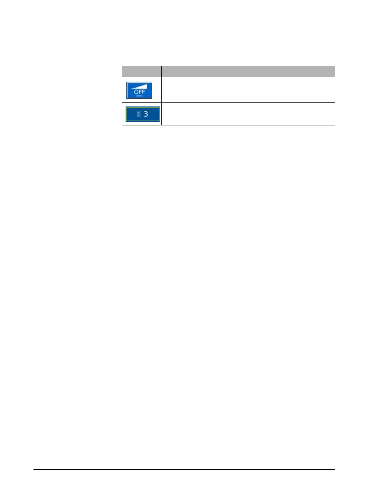
Table 2-2: Symbols used on graphical user interface (continued)
Symbol Description
Ramp Time is OFF (no ramp time set).
Intentional leak. The number corresponds to the leak symbol printed on
Respironics masks.
2-14 Respironics V60 Ventilator User Manual 1047358 Rev A
Page 21

Chapter 3. General information
Intended use The Respironics V60 Ventilator is an assist ventilator and is intended to
augment patient breathing. It is intended for spontaneously breathing
individuals who require mechanical ventilation: patients with respiratory
failure, chronic respiratory insufficiency, or obstructive sleep apnea in a
hospital or other institutional settings under the direction of a physician.
The ventilator is intended to support pediatric patients weighing 20 kg (44 lb)
or greater to adult patients. It is also intended for intubated patients meeting
the same selection criteria as the noninvasive applications. The vent ilator is
intended to be used by qualified medical professional s, such as physicians,
nurses, and respiratory therapists. The ventilator is intended to be used only
with various combinations of Respironics-recommended patient circuits,
interfaces (masks), humidifiers, and other accessories.
About CO2 rebreathing
As with mask ventilation in general, patient CO2 rebreathing may occur under
some circumstances. Follow these guidelines to minimize the potential for CO
rebreathing. If rebreathing is a significant concern for a particular patien t a nd
these guidelines are not sufficient to acceptably reduce the potential for CO
rebreathing, consider an alternative means of ventilation.
• Increase EPAP to decrease the potential for CO
pressures produce more flow through the exhalation port, which helps
to purge all CO
• Be aware that the potential for CO
inspiratory time increases. A longer inspiratory time decreases
exhalation time, allowing less CO
the next cycle. In such circumstances, higher tidal volumes further
increase the volume of CO
from the circuit to prevent rebreathing.
2
rebreathing increases as
2
to be purged from the circuit before
2
rebreathed by the patient.
2
rebreathing. Higher
2
Potential side effects Advise the patient to immediately report any unusual chest discomfort,
shortness of breath, or severe headache. Other potential side effects of
noninvasive positive pressure ventilation include: ear discomfort,
conjunctivitis, skin abrasions due to mask/patient interface, and gastric
distention (aerophagia). If skin irritation or breakdown develops from the use of
the mask, refer to the accompanying mask instructions for appropriate action.
2
2
1047358 Rev A Respironics V60 Ventilator User Manual 3-1
Page 22
Chapter 3
General information
Contraindications The Respironics V60 Ventilator is contraindicated for patients with any of the
following conditions:
• Lack of spontaneous respiratory drive
• Inability to maintain a patent airway or adequately clear secretions
• At risk for aspiration of gastric contents
• Acute sinusitis or otitis media
• Hypotension
• Untreated pertussis
• Epistaxis (nosebleed)
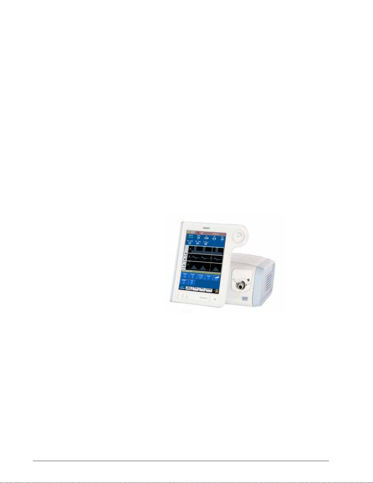
General description The Respironics V60 Ventilator (Figure 3-1) is a microprocessor-controlled,
bilevel positive airway pressure (BiPAP) ventilatory assist system that provides
noninvasive positive pressure ventilation (NPPV) and invasive ventilatory
support for spontaneously breathing adult and pediatric patie nts.
Figure 3-1: Respironics V60 Ventilator
Ventilation modes. The ventilator offers a range of conventional pressure
modes, CPAP (continuous positive airway pressure), PCV (pressure-controlled
ventilation), and S/T (spontaneous/timed). The volume-targeted AVAPS
(average volume-assured pressure support) mode combines the attributes of
pressure-controlled and volume-targeted ventilation.
Auto-Trak Sensitivity allows the ventilator to automatically compensate for
unintentional leaks by maintaining a stable baseline and adjusting trigger and
cycle thresholds for optimum patient-to-ventilator synchrony.
User interface. The ventilator’s ergonomic design, including a 12.1-inch (31cm) color touchscreen, a navigation ring, and key panel, lets you easily access
ventilator settings and monitored parameters.
3-2 Respironics V60 Ventilator User Manual 1047358 Rev A
Page 23

Chapter 3
General information
Monitoring. The ventilator displays monitored parameters as numbers and as
real-time waveforms (curves or scalars).
Alarms. The ventilator’s operator-adjustable and nonadjustable alarms help
ensure the patient’s safety.
Power and gas supplies. The ventilator uses as its primary power source AC
mains. An optional internal backup battery powers the ventilator typically for
6 hours.
The ventilator uses high-pressure oxygen. An integral blower pressurizes gas for
delivery to the patient.
Mounting. The ventilator can be mounted to the universal stand. When
equipped with the optional cylinder holder, the stand can accommodate two Esize oxygen cylinders.
Communications interface. The ventilator can output data through the RS-232
serial port upon receiving a command from a host computer or bedside
monitoring system. The ventilator is equipped with a remote alarm/nurse call
connection to activate alarms remotely.
Upgradability via Respironics Respi-Link
remote diagnostic system. The Respi-
Link interface permits software upgrade and remote troubleshooting of the
ventilator through the RS-232 port.
1047358 Rev A Respironics V60 Ventilator User Manual 3-3
Page 24
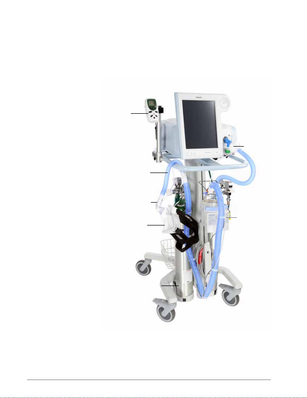
Chapter 3
Oxygen
monitor
Humidifier
Oxygen
cylinder
Patient circuit
Mask
Bacteria filter
Exhalation port
General information
Physical description Patient circuits, masks/patient interfaces, and accessories
Figure 3-2 shows the Respironics V60 Ventilator with its patient circuit and
accessories. T a ble 3-1 on page 3-5 lists recommended patient circuits, masks/
patient interfaces, and other accessories for use with the ventilator. Appendix
D provides ordering information for Respironics parts and accessories.
3
Figure 3-2: Respironics V60 Ventilator with accessories
3-4 Respironics V60 Ventilator User Manual 1047358 Rev A
Page 25
Chapter 3
General information
Table 3-1: Recommended parts and accessories
Part Use...
Patient circuit Single-limb patient circuit intended for
noninvasive or invasive ventilation. To minimize turbulence, we recommend that you
use smooth-bore tubing. Use a Respironics
circuit listed in Appendix D or the equivalent.
Patient interface (noninvasive or invasive) • Respironics masks listed in Appendix D
• Invasive interface (tracheostomy or ET
tube)
Exhalation port Respironics exhalation port listed in Ap pen-
dix D or the equivalent
Inspiratory filter Respironics main flow (inspiratory) bacteria
filter listed in Appendix D or the equivalent
Humidifier • Fisher & Paykel
• Hudson RCI CONCHATHERM or
CONCHATHERM Neptune
Oxygen monitor • CRITERION
(PN 8-100661-00)
• Teledyne MX300 oxygen monitor
• An equivalent that complies with ISO
7767
MR810 or MR850
OxiCheck oxygen analyzer
1047358 Rev A Respironics V60 Ventilator User Manual 3-5
Page 26
Chapter 3
1
6
5
4
2
3
Key panel
789
General information
Ventilator unit
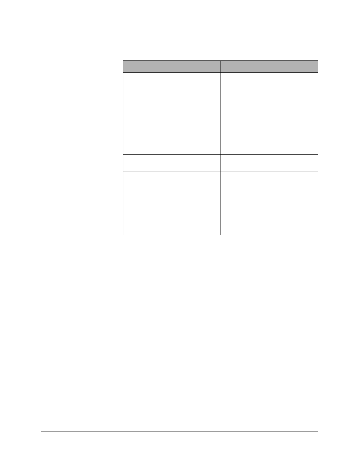
Figure 3-3 through Figure 3-5 show the controls, indicators, and other
important parts of the ventilator unit .
Figure 3-3: Front view
Number Description
1 Graphical user interface. Color LCD (liquid crystal display) with touchscreen.
2 Navigation ring. Lets you adjust values and navigate the graphical user interface
by rotating the finger on its touchpad.
3 Accept button. Activates selections.
4 Proximal pressure port. Connection for tubing that monitors patient pressure in
5 Ventilator outlet (To patient) port. Main connection for the patient circuit. Deliv-
6 Alarm speakers (beneath ventilator)
7 Alarm LED. Flashes during a high-priority alarm. On continuously during a venti-
8 Battery (charged) LED. Flashes when battery is charging. On continuously when
9 ON/Shutdown key with LED. T urns on AC power and initi ates ventilator shutdown.
the patient circuit.
ers air and oxygen in prescribed pressures to the patient.
lator inoperative condition.
battery is charged. Off when ventilator is running on battery or when the venti-
lator is off and AC power is not connected.
LED is continuously on when AC power is connected.
3-6 Respironics V60 Ventilator User Manual 1047358 Rev A
Page 27
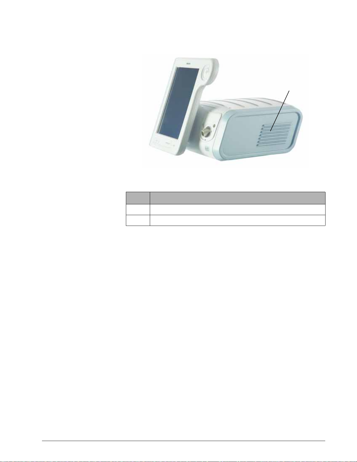
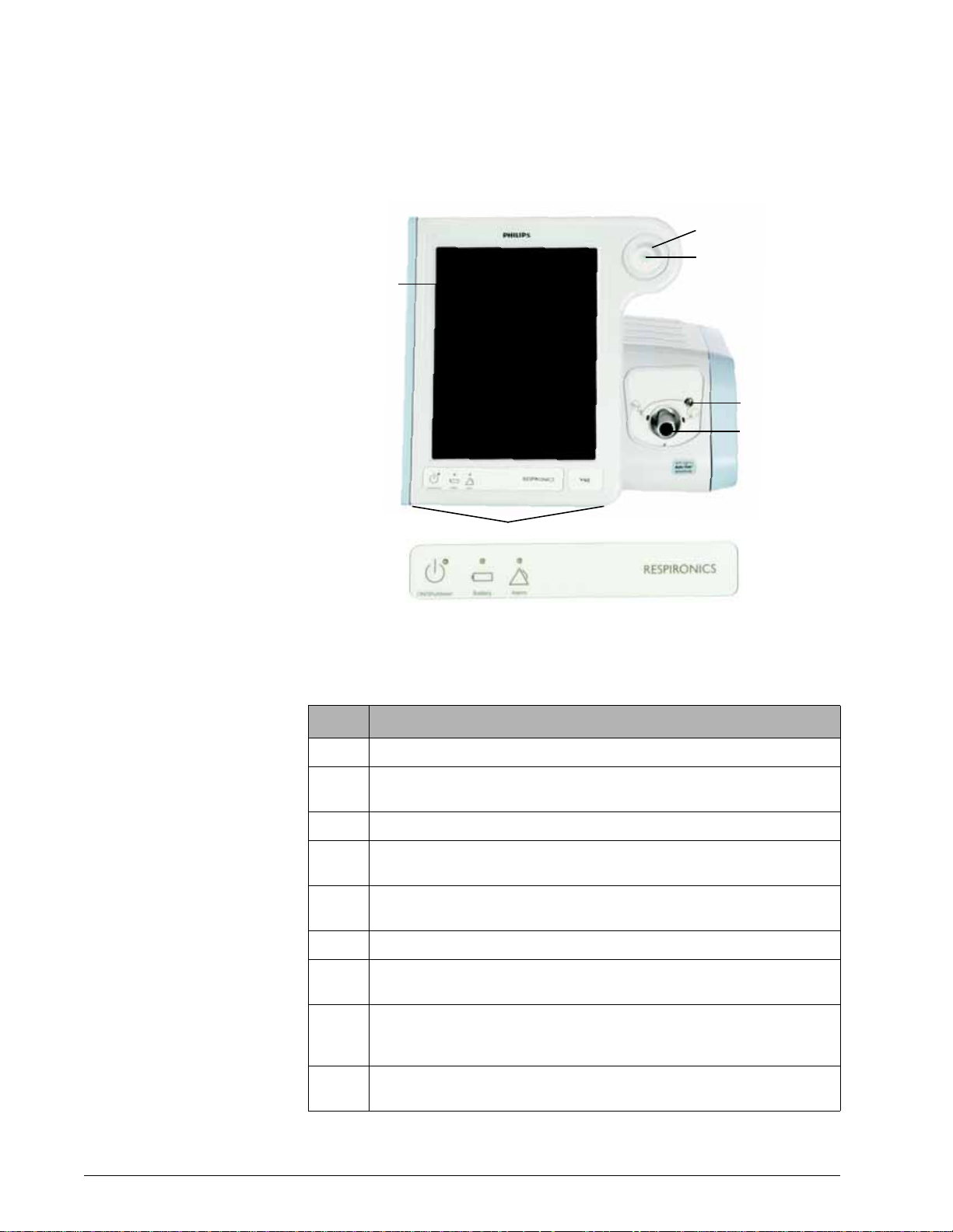
Figure 3-4: Side view
1
2
Chapter 3
General information
Number Description
1 Ventilation vents. Allow intake of air for delivery to the patient.
2 Air inlet filter (under side panel). Filters the air for delivery to the patient.
1047358 Rev A Respironics V60 Ventilator User Manual 3-7
Page 28
Chapter 3
83
1
7 3 6 54 3 2
General information
Figure 3-5: Rear view
Number Description
1 Backup battery (compartment under side panel). Optional, 6-hour backup bat-
tery.
2 Remote alarm/nurse call connector
3 Reserved for future use
4 Power cord retainer
5 Power cord
6 RS-232 serial and analog I/O connector (female DB-25). Connects to hospital
information systems and other serial devices, and functions as an interface
for analog signals. Connects Respi-Link
for software updates.
7 Cooling fan filter
8 High-pressure oxygen inlet connector
remote diagnostic system gateway
3-8 Respironics V60 Ventilator User Manual 1047358 Rev A
Page 29
Chapter 3
15
Window/window tabs
(see page 6-1)
Help button
(see page 6-14)
Waveforms window
(see page 7-1)
Patient data window
(see page 7-1)
Power symbols
(see page 5-5)
Alarm status bar
(see page 8-2)
Compressed waveforms window with Alarms/
Messages list
(see page 8-2)
General information
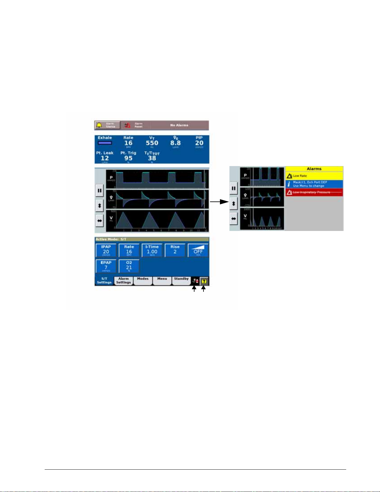
Graphical user interface
Through the graphical user interface (Figure 3-6) you make ventilator settings
and view ventilator and patient data. During ventilation, the upper screen
displays alarms and patient data. The middle screen displays real-time
waveforms and alarm and informational messa ges. The lower screen lets you
access modes and other ventilator settings, display help information, and see
.
the power status.
1047358 Rev A Respironics V60 Ventilator User Manual 3-9
Figure 3-6: Parts of graphical user interface
Page 30

Chapter 3
General information
(This page is intentionally blank.)
3-10 Respironics V60 Ventilator User Manual 1047358 Rev A
Page 31

Chapter 4. Principles of operation
System operational overview
The Respironics V60 Ventilator is a microprocessor-controlled pneumatic
system that delivers a mixture of air and oxygen. It is powered by AC with
optional battery backup to protect against power failure or unstable power and
to facilitate intrahospital transport. The ventilator’s pneumatics deliver gas and
its electrical systems control pneumatics, monitor the patient, and distribute
power.
The user provides inputs to the ventilator through a touchscreen, keys, and a
navigation ring. These inputs become instructions for the pneumatics to
deliver a precisely controlled gas mixture to the patient. Pressure and flow
sensors provide feedback, which is used to adjust gas delivery to the patient.
Monitored data based on sensor inputs is also displayed by the graphical user
interface.
The ventilator’s gas delivery and monitoring functions are cross-checked. This
cross-checking helps prevent simultaneous failure of these two main functions
and minimizes the possible hazards of system failure.
A comprehensive system of visual and audible alarms helps ensure the
patient’s safety. Clinical alarms can indicate an abnormal physiological
condition. Technical alarms, triggered by the ventilator’s self-tests, can
indicate a hardware or software failure. In the case of some technical alarms,
limited ventilation is provided to give the user time for corrective actions.
When a condition is critical enough to possibly compromise safe ventilation,
the ventilator is placed into the ventilator inoperative state, in which oxygen
flow and blower operation are disabled.
The ventilator has several means to ensure that safe patient or respiratory
pressures are maintained. The maximum working pressure is ensured by the
high inspiratory pressure (HIP) alarm limit. If the set high pressure limit is
reached, the ventilator cycles into exhalation.
1047358 Rev A Respironics V60 Ventilator User Manual 4-1
Page 32

Chapter 4
Respironics V60 Ventilator
Blower
High-
pressure
oxygen
Ambient
air
Proximal (patient)
pressure
Ventilator outlet
(machine)
pressure
Air flow
sensor
Mixer
Proportioning
O2 flow
sensor
Air inlet
filter
Main flow
filter
Patient
Exhalation
port
O2 pressure
Principles of operation
Pneumatic system operation
The ventilator uses ambient air and high-pressure oxygen (Figure 4-1). Air
enters through an inlet filter. Oxygen enters though a high-pressure inlet, and a
proportioning valve provides the operator-set concentration. The system mixes
the air and oxygen, pressurizes it in the blower, and then regulates it to the
user-set pressure. To do this, the ventilator compares the proximal (patient)
pressure measurement with the vent ilator outlet (machine) pressure, and
adjusts the machine pressure to compensate for the pressure drop across the
inspiratory filter, patient circuit, and humidifier. This helps ensure accurate
and responsive pressure delivery and leak compensation.
Figure 4-1: Respironics V60 Ventilator gas delivery system
The ventilator delivers gas to the patient through a main flow (inspiratory)
bacteria filter, a single-limb patient breathing circuit, a humidification device
(optional) and a patient interface such as a mask or ET tube. A pressure tap
proximal to the patient is used to monitor patient pressure. The exhalation port
continually exhausts gas from the circuit during inspiration and exhalation to
minimize rebreathing and ensure CO
removal.
2
Breath delivery characteristics
Control variable
Breaths delivered by the Respironics V60 Ventilator are pressure controlled. In
the AVAPS mode, the ventilator’s applied pressure is automatically adjusted
over several breaths to maintain a target tidal volume.
Triggering, cycling, and leak adaptation
Unlike other ventilators, the Respironics V60 Ventilator does not require you to
set triggering and cycling sensitivity or to adjust baseline flow.The ventilator’s
unique Auto-Trak Sensitivity algorithm adjusts these automatically; see “AutoTrak Sensitivity” on page 4-3.
Baseline pressure
4-2 Respironics V60 Ventilator User Manual 1047358 Rev A
A positive baseline pressure (EPAP or CP AP) may be set for all breaths in all modes.
Page 33

Chapter 4
Principles of operation
Pressure rise time
The operator-set Rise Time defines the time required for inspiratory pressure to
rise to the set (target) pressure.
Negative pressures
There are no negative pressures generated during exhalation.
Oxygen concentration
The Respironics V60 Ventilator incorporates an oxygen mixer. Oxygen
concentration can be set in all modes.
Auto-Trak Sensitivity An important characteristic of the Respironics V60 Ventilator is its ability to
recognize and compensate for unintentional leaks in the system and to
automatically adjust its triggering and cycling algorithms to maintain optimum
performance in the presence of leaks. This is called Auto-Trak Sensitivity. The
following subsections describe this func tion in detail.
Triggering
Breaths are patient (flow) triggered in all modes, typically when patient effort
causes a certain volume of gas to accumulate above
method). An inspiration is also triggered when the patient inspiratory
the expiratory flow waveform sufficiently (shape signal method; see page 4-4).
baseline flow (volume
effort distorts
Cycling
Cycling to exhalation occurs in these cases:
• Patient expiratory
sufficiently (shape signal method). See “Shape signal method of
cycling and triggering.” on page 4-4.
• Patient flow reaches the spontaneous exhalation threshold (SET). See
“SET method of cycling.” on page 4-4.
• After 3 seconds at the IPAP level (timed backup safety mechanism)
• When a flow reversal occurs, typically due to a mask or mouth leak
effort distorts the inspiratory flow waveform
1047358 Rev A Respironics V60 Ventilator User Manual 4-3
Page 34

Chapter 4
Estimated
patient flow
Shape
signal
Cycle to exhalation
crossover point
Trigger to
inspiration
crossover point
Spontaneous
exhalation threshold
Principles of operation
Shape signal method of cycling and triggering. The shape signal or “shadow
trigger” method uses a mathematical model derived from the flow signal. A
new flow signal (shape signal) is generated by offsetting the signal from the
actual flow and delaying it (Figure 4-2). This intentional delay causes the flow
shape signal to be slightly behind the patient’s flow signal. If there is a sudden
change in patient flow, the patient’s flow signal crosses the shape signal; this
results in a trigger or a cycle. As a resul t, a su dden d ecr ease in exp ira tory f low
from an inspiratory effort will cross the shape signal and create a signal for
ventilator triggering.
Figure 4-2: Shape signal
SET method of cycling. Patient flow reaches the spontaneous exhalation
threshold (SET); see Figure 4-3. The SET represents the intersection of the
flow waveform and a line of a given slope. SET is updated each breath.
Figure 4-3: Spontaneous exhalation threshold (SET)
4-4 Respironics V60 Ventilator User Manual 1047358 Rev A
Page 35

Chapter 4
Flow
TIME
Original
baseline
Inspiration
Spontaneous
trigger
Cycle to
exhalation
End exhalation
Adjustment
of baseline
New
baseline
Patient
flow
Additional
leak
Principles of operation
Leak adaptation
Noninvasive ventilation in particular may involve considerable leakage around
the mask or through the mouth. Some leakage is known or intentional: it is a
characteristic of the mask/patient interface design. So that it can accurately
adjust its baseline flow, the ventilator has you enter the intentional leakage
value specific to the mask/patient interface (“Selecting the mask and
exhalation port” on page 6-7). Other leakage is unpredictable or unintentional,
and it changes as the patient’s breathing pattern changes.
To maintain prescribed pressures in the presence of leakage, the ventilator
adjusts its baseline flow. Because the unintentional part of the leakage may
constantly change, the ventilator recalculates the baseline flow each breath at
the end of exhalation. The ventilator uses two main mechanisms to update its
baseline flow: expiratory flow adjustment and tidal volume adjustment.
Expiratory flow adjustment. Every breath, at end-exhalation, the ventilator
updates its flow baseline. At end-exhalation patient flow is assumed to be zero,
so any difference between actual patient flow and the original baseline flow
indicates a change in leakage. Figure 4-4 shows how the ventilator adjusts the
baseline.
1047358 Rev A Respironics V60 Ventilator User Manual 4-5
Figure 4-4: Expiratory flow adjustment
Page 36

Chapter 4
Additional leak
introduced
New baseline
Volume adjustment
Flow
Volume
Principles of operation
Tidal volume adjustment. Every breath, the ventilator compares the inspiratory
and expiratory tidal volumes. Any difference is assumed to be due to an
unintentional circuit leak. The ventilator adj usts the ba seline to reduce this
tidal volume difference for the next breath . Figure 4-5 shows how the
ventilator adjusts the baseline.
Figure 4-5: Tidal volume adjustment
4-6 Respironics V60 Ventilator User Manual 1047358 Rev A
Page 37

Chapter 4
Principles of operation
Ventilation modes The Respironics V60 Ventilator operates in the following ventilation modes:
• CPAP (continuous positive airway pressure) mode
• S/T (spontaneous/timed) mode
• PCV (pressure-controlled ventilation) mode
• AVAPS (average volume-assured pressure support) mode (optional)
Table 4-1 summarizes the characteristics of these modes. Note that on the
ventilator, the Timed breath indicator means the breath is ventilator triggered,
while the Spont breath indicator means the breath is patient triggered.
Table 4-1: Characteristics of Respironics V60 ventilation modes
Mandatory breaths Spontaneous breaths
Mode
CPAP N/A N/A N/A Auto-Trak Pressure Auto-Trak
PCV Time,
S/T Time,
AVAPS Time,
* A trigger variable starts inspiration.
† A limit variable can reach and maintain a preset level before inspiration ends but it does not
end inspiration.
‡ A cycle variable is a measured parameter used to end inspiration.
*
Trigger
Auto-Trak
Auto-Trak
Auto-Trak
†
Limit
Pressure Time N/A N/A N/A
Pressure Time Auto-Trak Pressure Auto-Trak
Pressure Time,
‡
Cycle
Auto-Trak
Trigger Limit Cycle
Auto-Trak Pressure Auto-Trak
1047358 Rev A Respironics V60 Ventilator User Manual 4-7
Page 38

Chapter 4
Volume Flow
Pressure
CPAP
I E
Time
Principles of operation
CPAP mode
In the CPAP (continuous positive airway pressure) mode, the ventilator
functions as a demand flow system, with the patient triggering all breaths and
determining their timing, pressure, and size. You set no triggering or cycling
sensitivities: the patient triggers and cycles based on the ventilator’s Auto-Trak
Sensitivity algorithms. The control settings active in the CPAP mode are shown
in Figure 4-6. Figure 4-7 shows CPAP mode waveforms.
The optional C-Flex setting enhances traditional CPAP by reducing the
pressure at the beginning of exhalation – a time when patients may be
uncomfortable with CPAP – and returning it to the set CPAP level before the
end of exhalation.
Figure 4-6: CPAP controls
Figure 4-7: CPAP waveforms
4-8 Respironics V60 Ventilator User Manual 1047358 Rev A
Page 39

Chapter 4
Pressure
EPAP
IPAP
I-TIme
1/Rate
Machine-triggered
(Timed) breath
Rise
Time
Patient-triggered
(Spont) breath
Principles of operation
PCV mode
The PCV (pressure-controlled ventilation) mode delivers pressure-controlled
mandatory breaths, either triggered by the ventilator (Timed) or the patient
(Spont). You set no triggering sensitivity: the patient trigger is based on the
ventilator’s Auto-Trak Sensitivity algorithms. The control settings active in the
PCV mode are shown in Figure 4-8. The IPAP setting defines the applied
pressure for all breaths. Rate and I-Time define the breath timing for all
breaths. You set no triggering or cycling thresholds: the ventilator’s Auto-Trak
Sensitivity algorithms automatically determine when to trigger and cycle based
on patient efforts. Figure 4-9 shows a PCV mode pressure waveform.
Figure 4-8: PCV controls
Figure 4-9: PCV pressure waveform
1047358 Rev A Respironics V60 Ventilator User Manual 4-9
Page 40

Chapter 4
Pressure
EPAP
IPAP
I-TIme
1/Rate
Patient-triggered (Spont)
spontaneous breath with
pressure support
Mandatory
(Timed) breath
Time
Rise
Principles of operation
S/T mode
The S/T (spontaneous/timed) mode guarantees breath delivery at the user-set
rate. It delivers pressure-controlled, time-cycled mandatory and pressuresupported spontaneous breaths, all at the IPAP pressure level. If the patient
fails to trigger a breath within the interval determined by the Rate setting, the
ventilator triggers a mandatory breath with the set I-Time. You set no patient
triggering or cycling sensitivities: the patien t triggers and cycles based on the
ventilator’s Auto-Trak Sensitivity algorithms. The control settings active in the
S/T mode are shown in Figure 4-10. Figure 4-11 shows an S/T mode pressure
waveform.
Figure 4-10: S/T controls
Figure 4-11: S/T pressure waveform
4-10 Respironics V60 Ventilator User Manual 1047358 Rev A
Page 41

Chapter 4
Principles of operation
AVAPS mode (optional)
NOTE: When you adjust AVAPS minimum and maximum pressures,
remember that IPAP is adjusted to meet the target value. If the
calculated target pressure is outside of the minimum and maximum
pressure range, the target volume will not be achieved.
Unlike most pressure modes, the AVAPS (average volume-assured pressure
support) mode delivers a target tidal volume. It achieves the target volume by
regulating the pressure applied followin g an initial pressure ramp-up. The
AVAPS mode delivers time-cycled mandatory breaths and pressure-supported
spontaneous breaths.
If the patient fails to trigger a breath within the interval determined by the
Rate control, the ventilator triggers a mandatory breath with the set I-Time.
Mandatory and spontaneous breaths are delivered at a pressure that is
continually adjusted over a period of time to achieve the volume target, V
Min P and Max P define the minimum and maximum pressures that can be
applied. You set no patient triggering or cycling sensitivities: the patient
triggers and cycles based on the ventilator’s Auto-Trak Sensitivity algorithms.
.
T
The control settings active in the AVAPS mode are shown in Figure 4-12.
Figure 4-13 shows AVAPS mode waveforms.
Figure 4-12: AVAPS controls
1047358 Rev A Respironics V60 Ventilator User Manual 4-11
Page 42

Chapter 4
Volume Flow
Pressure
Max P
Min P
V
T
EPAP
1/Rate
I-TIme
Mandatory (Timed)
breath
Patient-triggered (Spont)
spontaneous breath
Rise
Time
Principles of operation
Figure 4-13: AVAPS waveforms
4-12 Respironics V60 Ventilator User Manual 1047358 Rev A
Page 43

Chapter 5. Preparing for ventilation
Set up the ventilator for each patient use as described in this chapter. For firsttime installation, refer to Appendix A.
Connecting external devices
You can connect the ventilator to a remote alarm (nurse call) device and a
patient monitor or other external device. See Appendix B for details.
Connecting oxygen WARNING: Connect the ventilator to an appropriate medical-grade oxygen source
only. The source must be able to deliver 100% oxygen regulated to 276
to 600 kPa (40 to 87 psig).
WARNING: To ensure accuracy of oxygen administration and to monitor for the
presence of contamination (incorrect gas connected), use an external
oxygen monitor to verify the oxygen concentration in the delivered gas.
WARNING: To reduce the risk of fire, do not use a high-pressure oxygen hose that is
worn or contaminated with combustible materials like grease or oil.
WARNING: To reduce the risk of hypoxia, connect only oxygen to the high-pressure
connector at the rear of the ventilator.
WARNING: Always check the status of the oxygen cylinders before using the
ventilator during transport.
CAUTION: To prevent possible damage to the ventilator, ensure that the
connection to the oxygen supply is clean and unlubricated, and that
there is no water in the oxygen supply gas.
NOTE: To avoid depleting the cylinders, close the cylinder valves when using
the wall oxygen supply.
Connect the oxygen hose to the ventilator’s oxygen inlet connector (Figure 5-1)
or to the oxygen manifold, if applicable.
1047358 Rev A Respironics V60 Ventilator User Manual 5-1
Page 44

Chapter 5
Oxygen inlet
connector
Preparing for ventilation
Figure 5-1: Oxygen inlet connector
Installing the patient circuit
WARNING: To reduce the risk of strangulation from patient tubing, use a tubing
support arm and secure the proximal pressure line with clips.
WARNING: To prevent possible patient injury and possible water damage to the
ventilator, make sure the humidifier is set to appropriate temperature and
humidification settings.
WARNING: To prevent possible patient injury and equipment damage, do not turn the
humidifier on until the gas flow has started and is regulated. Starting the
heater or leaving it on without gas flow for prolonged periods may result
in heat build-up, causing a bolus of hot air to be delivered to the patient.
Circuit tubing may melt under these conditions. Turn the heater power
switch off before stopping gas flow.
WARNING: To reduce the risk that the patient will aspirate condensed water from the
breathing circuit, position any humidifier lower than both the ventilator
and the patient.
WARNING: To reduce the risk of fire, use only patient circuits intended for use in
oxygen-enriched environments. Do not use antistatic or electrically
conductive tubing.
WARNING: To prevent patient or ventilator contamination, we recommend you use a
Respironics-approved main flow bacteria filter on the patient gas outlet
port. Filters not approved by Respironics may degrade system
performance.
WARNING: To reduce the risk of bacterial contamination or damage, handle bacteria
filters with care.
WARNING: Any additional accessories in the patient circuit may substantially
increase flow resistance and impair ventilation.
5-2 Respironics V60 Ventilator User Manual 1047358 Rev A
Install the patient circuit as follows. For a complete list of compatible parts
and accessories offered by Respironics, see “Parts and accessories” on
page D-1.
1. Assemble the patient circuit, including the main flow (inspiratory)
bacteria filter, proximal pressure line, and humidifier (if desired).
Figure 5-2 and Figure 5-3 show circuit configurations for noninvasive
Page 45

Chapter 5
Proximal pressure line
Ventilator
outlet
Bacteria filter
Proximal
pressure
port
Ventilator
outlet
Proximal pressure line
Water trap
Humidifier
Proximal filter
Bacteria filter
Proximal
pressure
port
Preparing for ventilation
and invasive ventilation. Follow the manufacturers’ instructions for use
for the individual parts, including the humidifier.
Figure 5-2: Noninvasive patient circuit, without humidification
Figure 5-3: Invasive patient circuit, with humidification
2. Properly position the patient circuit after assembly. Make sure the
1047358 Rev A Respironics V60 Ventilator User Manual 5-3
tubing will not be pushed, pulled, or kinked during patient movement
or other procedures.
Page 46

Chapter 5
Preparing for ventilation
Connecting to AC power
WARNING: To reduce the risk of electric shock, connect the ventilator to an AC
supply mains with protective earth only.
WARNING: Do not use extension cords, adapters, or power cords with the ventilator
that are not approved by Respironics.
WARNING: To prevent unintentional disconnection of the power cord, always use the
correct, Respironics-supplied power cord and lock it into place with the
power cord retainer before you switch the ventilator on. The retainer is
designed to hold the connector end of the Respironics-supplied cord
securely in place.
WARNING: To reduce the risk of electric shock, regularly inspect the AC power cord
and verify that it is not frayed or cracked.
WARNING: To reduce the risk of strangulation, route the power cord to avoid
entanglement.
CAUTION: For 120 V equipment, grounding reliability can only be achieved
when it is connected to an equivalent receptacle marked “hospital
only” or “hospital grade.”
Plug the power cord into a grounded outlet that supplies AC power between
100 and 240 V, 50/60 Hz.
Always check the reliability of the AC outlet. If you are using a 120 V outlet,
make sure that it is hospital grade.
About the optional backup battery
WARNING: To reduce the risk of power failure, pay close attention to the battery’s
charge level. The battery’s operation time is approximate and is affected
by ventilator settings, discharge and recharge cycles, battery age, and
ambient temperature. Battery charge is reduced at low ambient
temperatures or in situations where the alarm is continuously sounding.
NOTE: The backup batteries are intended for short-term use only. They are
not intended to be a primary power source.
NOTE: We recommend that the ventilator’s batteries be fully charged before
you ventilate a patient. If the batteries are not fully charged and AC
power fails, always pay close attention to the level of battery charge.
The optional internal backup battery protects the ventilator from low, or failure
of, AC (mains) power . If AC power fails, the ventilator automatically switches to
operation on backup battery with no interruption in ventilation. The battery
powers the ventilator until AC power is again adequate or until the battery is
depleted. The battery powers the ventilator typically for 6 hours.
As a safeguard, the ventilator provides a low battery alarm. It also has a
capacitor-driven backup alarm that sounds for at least 2 minutes when battery
power is completely lost.
The ventilator charges the battery whenever the ventilator is connected to AC,
with or without the ventilator switched on. The Battery (charged) LED flashes
to show that the battery is being charged.
5-4 Respironics V60 Ventilator User Manual 1047358 Rev A
Page 47

Chapter 5
ON/Shutdown LED
On continuously: AC
power is connected
Battery (charged) LED
Flashes: Battery is charging
On continuously: Battery is charged
(90 to 100%)
Off: Ventilator is running on battery,
or the ventilator is off and AC power
is not connected
Power source symbol
The ventilator is powered by AC
and the battery is installed.
The ventilator is powered by AC
and the battery is not installed.
The ventilator is powered by the
battery. This symbol shows the approximate battery time remaining
in hours and minutes, and it shows
the capacity graphically.
Preparing for ventilation
Check the battery charge level before putting a patient on the ventilator and
before unplugging the ventilator for transport or other purposes. The power
source symbol at the bottom right-hand corner of the screen shows the power
source in use and, if the ventilator is running on battery, the level of battery
charge (Figure 5-4). If the ba ttery is not fully charged, recharge it by
connecting the ventilator to AC power for a minimum of 5 hours. Pressing the
Help button shows you the time remaining until the battery is full. If the
battery is not fully charged after this time, have the ventilator serviced.
Figure 5-4: Power indicators
1047358 Rev A Respironics V60 Ventilator User Manual 5-5
Page 48

Chapter 5
Preparing for ventilation
Starting up the ventilator
Shutting down the ventilator
NOTE: Upon power-on the ventilator automatically runs a test of the backup
audible alarm followed by the primary audible alarm. You should hear
two high-pitched tones, followed by a beep approximately 2 seconds
later. If you do not hear all of these sounds, discontinue use of the
ventilator and have it serviced.
1. Power on the ventilator with the ON/Shutdown key.
2. Run the preoperational check on page 5-8.
Shut down the ventilator as follows:
1. Press and release the ON/Shutdown key. The Shutdown window opens.
2. Select Ventilator Shutdown. The ventilator shuts down.
NOTE: Improper shutdown may cause a Loss of Power Alarm message the next
time the ventilator is turned on.
NOTE: If the screen is blank and the dialogue box cannot be displayed, shut
down the ventilator by pressing the ON/Shutdown key , then the Accept
button on the navigation ring.
5-6 Respironics V60 Ventilator User Manual 1047358 Rev A
Page 49

Chapter 5
Adjustment
arrow button
Slider flag
Setting range scale
Proposed value
Preparing for ventilation
Navigating the graphical user interface
Select a function by touching the desired tab or button on the touchscreen.
Use this as the primary method to control the ventilator.
You can use the navigation ring as an alternative to the following touchscreen
functions:
Touchscreen equivalent Navigation ring equivalent
Touch increase button (adjustment
arrow)
Touch decrease button (adjustment
arrow)
Touch Accept button (applies selection)
Touch and rotate finger clockwise to increase value or move cursor forward
Touch and rotate finger counterclockwise to decrease value or move cursor
backward
Press Accept (checkmark)
button (applies selection)
After making selections and adjusting values, accept selections by pressing the
circular Accept button (the checkmark) in the middle of the navigation ri ng to
accept and apply the change.
To open a window, touch the window tab.
To cancel a function and close the window, either select Cancel or touch another
window tab.
To adjust a parameter, touch the arrow buttons repeatedly or select the value
with the navigation ring. The slider flag moves along the setting range scale.
Select Accept to apply.
The navigation ring also lets you adjust the position of the cursor in the
waveforms window while the screen is frozen. See “Freezing and unfreezing
waveforms” on page 7-3 for more information.
1047358 Rev A Respironics V60 Ventilator User Manual 5-7
Page 50

Chapter 5
Preparing for ventilation
Preoperational check WARNING: To ensure the ventilator’s safe operation, always run the full
preoperational check described in “Preoperational check” on page 5-8
before using the ventilator on a patient. If the ventilator fails any tests,
remove it from clinical use immediately. Do not use the ventilator until
necessary repairs are completed and all tests have passed.
WARNING: To prevent possible patient injury, disconnect the patient from the
ventilator before running the preoperational check. Make sure another
source of ventilatory support is available.
Before you connect a new patient to the ventilator, run the preoperational
check to verify the ventilator’s operation, including alarm functionality.
Required materials
To ensure that the ventilator also functions according to specifications on your
patient, we recommend that your test circuit be equivalent to the circuit used
for ventilation.
• Breathing circuit, PN 582073 or the equivalent
• 1-L test lung, PN 1021671 or the equivalent
• CRITERION
Teledyne MX300 oxygen monitor, or the equivalent
OxiCheck oxygen analyzer (PN 8-100661-00),
Procedure
Do or observe... Verify...
1. Connect ventilator to AC power and the
oxygen supply. Assemble the patient
breathing circuit.
2. Switch on power. You hear two high-pitched tones, followed
3. Check active mask and exhalation port
selection in Messages list.
4. Set the mode to S/T and make the
following control settings: Rate: 4 BPM,
IPAP: 10 cmH
I-Time: 1 sec, Rise: 1, Ramp: Off, O
21%. Make the following alarm settings:
Hi Rate: 90 BPM, Lo Rate: 1 BPM, Hi
V
: 200 mL, Lo VT: OFF, HIP:
T
50 cmH
5. Disconnect the proximal airway pressure
line from the ventilator connector.
O, EPAP: 6 cmH2O,
2
O, LIP: OFF, Lo VE: OFF.
2
Breathing circuit is assembled correctly.
See Figure 5-2 on page 5-3 or Figure 5-3
on page 5-3.
by a beep approximately 2 seconds later.
Displayed mask and exhalation port match
ones in use (see “Selecting the mask and
exhalation port” on page 6-7).
Test lung expands during inspiration and
collapses during exhalation. There is a continuous flow of gas from the exhalation
port.
:
2
Proximal Pressure Line Disconnect alarm is
annunciated (audio, visual, and flashing
Alarm LED) by the ventilator and remote
alarm, if connected.
5-8 Respironics V60 Ventilator User Manual 1047358 Rev A
Page 51

Do or observe... Verify...
Chapter 5
Preparing for ventilation
6. Reconnect the proximal airway pressure
line, and manually reset alarm.
7. Set O
8. Disconnect the ventilator from AC power
NOTE: If the ventilator has a backup
9. If the backup battery is installed,
to 40%. Wait for oxygen
2
concentration to stabilize.
while the ventilator is running.
battery, the battery must be
adequately charged to run this
test. Recharge as necessary
before running the test.
reconnect the ventilator to AC power.
Proximal Pressure Line Disconnect alarm is
reset.
Oxygen analyzer reads between 35 and
45%.
If the optional backup battery is installed:
• The ventilator switches over to battery
power (battery symbol in right-hand
corner of screen is displayed).
• The green LED above the ON/Shutdown
key remains lit.
• The audible alarm sounds intermittently.
• Running on Internal Battery is shown.
• The Battery LED is off.
If the optional backup battery is not installed:
• An alternating backup alarm tone sounds
and the Alarm LED flashes for a
minimum of 2 minutes.
• The alarm resets.
• The ventilator is again running on AC
(symbol displayed in right-hand corner of
screen).
• The Battery LED flashes to indicate the
battery is charging.
10.Return settings to hospital-standard
values.
WARNING:To preven t possible patient injury,
always return alarm settings to
hospital-standard values after the
preoperational check.
Troubleshooting
If any test step fails, discontinue ventilator use and contact Respironics.
1047358 Rev A Respironics V60 Ventilator User Manual 5-9
Page 52

Chapter 5
V
•
Preparing for ventilation
Alarm tests The ventilator performs a self-check during start-up and continuously during
operation. Alarm functionality is verified by this self-check. Yo u may also want
to run alarm tests, which demonstrate the alarms’ operation.
WARNING: To prevent possible patient injury, always return alarm settings to
hospital-standard values after the preoperational check.
Preparation
1. Set the ventilator up as for normal ventilatio n, complete with
breathing circuit (PN 582073 or the equivalent) and a 1-liter test lung
assembly (PN 1021671).
2. Set the mode to S/T and make the following control settings: Rate:
4 BPM, IPAP: 10 cmH2O, EPAP: 6 cmH
Ramp: Off, O
: 21%.
2
3. Make the following alarm settings: Hi Rate: 90 BPM, Lo Rate: 1 BPM,
Hi V
: 200 mL, Lo VT: OFF, HIP: 50 cmH2O, LIP: OFF, Lo E: OFF,
T
LIP T: 5 secs.
O, I-Time: 1 sec, Rise: 1,
2
High Inspiratory Pressure
1. Lower the HIP alarm limit to 8 cmH2O.
2. VERIFY that the High Inspiratory Pressure alarm is activated, the
ventilator cycles into exhalation, and pressure falls to 6 cmH
EPAP level).
3. Raise the HIP alarm limit to 15 cmH
O.
2
Low Tidal Volume
1. Raise the Lo VT alarm setting above the displayed, measured VT.
2. VERIFY that the Low Tidal Volume alarm is activated.
3. Turn the Lo V
4. VERIFY that the alarm resets.
alarm setting OFF.
T
O (the
2
5-10 Respironics V60 Ventilator User Manual 1047358 Rev A
Page 53

Preparing for ventilation
Patient Disconnect
1. Disconnect the test lung.
2. VERIFY that the Patient Disconnect alarm is activated.
3. Reconnect the test lung.
4. VERIFY that the alarm resets and that the ventilator automatically
resumes ventilation.
Patient Circuit Occluded
1. Disconnect the patient circuit (including bacteria filter) from the
ventilator outlet, and block the ventilator outlet with your thumb.
2. VERIFY that the Patient Circuit Occluded alarm is activated.
3. Unblock the outlet, and reconnect the circuit.
4. VERIFY that the alarm resets.
Chapter 5
1047358 Rev A Respironics V60 Ventilator User Manual 5-11
Page 54

Chapter 5
Preparing for ventilation
(This page is intentionally blank.)
5-12 Respironics V60 Ventilator User Manual 1047358 Rev A
Page 55

Chapter 6. Operation
page 6-3 page 6-6 page 6-2 page 6-11 page 6-12 page 6-14
WARNING: To ensure the ventilator’s safe operation, always run the full
preoperational check described in “Preoperational check” on page 5-8
before using the ventilator on a patient. If the ventilator fails any tests,
remove it from clinical use immediately. Do not use the ventilator until
necessary repairs are completed and all tests have passed.
NOTE: Before operation, prepare the ventilator as instructed in Chapter 5.
After power-on, the ventilator starts up in the mode and with the settings that
were active before last power down. Check these settings and adjust as
required. You must be familiar with using the touchscreen and navigation ring
to select, adjust, activate, and confirm parameters. For details, see
“Navigating the graphical user interface” on page 5-7.
Access the ventilator setting windows from the tabs at the bottom of the
screen.
1047358 Rev A Respironics V60 Ventilator User Manual 6-1
Page 56

Chapter 6
Active
mode
Operation
Changing the mode The active ventilation mode is displayed in the bottom, left-hand corner of the
screen. Change the mode as follows. For details on modes, see “Ventilation
modes” on page 4-7.
1. Open the Modes window.
2. Select the desired mode.
3. Adjust settings as desired (see “Changing individual ventilator
settings” on page 6-4). Newly adjusted setting values are shown in
yellow.
4. Select Activate Mode to apply.
6-2 Respironics V60 Ventilator User Manual 1047358 Rev A
Page 57

Chapter 6
Active
mode
Operation
Changing control settings
Table 6-3 on page 6-15 is an alphabetical list of the contro l settings wi th their
ranges. Table 10-2 on page 10-2 shows the control settings applicable to the
different modes. For more information on control settings as they apply in the
different ventilation modes, see “Ventilation modes” on page 4-7.
Making batch setting changes
NOTE: During a batch setting change, you cannot change the Ramp Time
setting when a ramp is active.
This process applies to ventilation settings only, not to alarm settings.
1. Open the Modes window.
2. Select the active mode.
3. Adjust settings as desired (see “Changing individual ventilator
settings” on page 6-4). Newly adjusted setting values are shown in
yellow.
4. Select Activate Batch Change to apply.
1047358 Rev A Respironics V60 Ventilator User Manual 6-3
Page 58

Chapter 6
Adjustment
arrow button
Current
settings area
Setting range scale
Additional
information
Proposed value
Operation
Changing individual ventilator settings
You can make ventilator settings from the Settings window.
1. Open the Settings window.
2. Select the desired setting. As an example we will show the IPAP
adjustment.
3. The setting window opens. Adjust the setting. Select Accept to apply.
6-4 Respironics V60 Ventilator User Manual 1047358 Rev A
Page 59

Chapter 6
Ramp
status
Bar
Operation
Using the Ramp Time function
The Ramp Time function helps your patient adapt to ventilation by gradually
increasing inspiratory and expiratory pressure (IPAP and EPAP/CPAP) from
subtherapeutic to user-set pressures over a user-set interval. Table 6-3 on
page 6-15 describes this function’s principles of operation.
Follow these instructions to use the Ramp Time function:
1. Select the Ramp Time button in the Settings window.
The ramp starts. As the ramp progresses, the Ramp Time button
graphic fills in.
2. To change the ramp interval or to end the ramp, select the Ramp Time
button again. The Ramp in Progress window opens.
3. To end the ramp and apply the full IPAP and EPAP/CPAP immediately,
select End Ramp.
4. To end the ramp and start a new one, select Start New Ramp. The Ramp
Time setting window opens again so that you can set up a new ramp.
1047358 Rev A Respironics V60 Ventilator User Manual 6-5
Page 60

Chapter 6
Operation
Changing alarm settings
WARNING: To prevent possible patient injury, avoid setting alarm limits to extreme
values, which can render the alarm system useless.
Some ventilator alarm settings are operator adjustable. You can adjust these at
any time. Table 6-4 on page 6-17 lists the alarm settings and their ranges.
Review and adjust the alarm settings as follows:
1. Open the Alarm Settings window.
2. Select the desired setting, adjust it, and select Accept to apply.
The ventilator annunciates an alarm when a monitored value goes out of the
range bounded by the alarm limit s.
6-6 Respironics V60 Ventilator User Manual 1047358 Rev A
Page 61

Chapter 6
Operation
Selecting the mask and exhalation port
T o be able to display full leakage data plus accurate tidal and minute volumes,
the ventilator must know the intentional leak characteristics of the specific
mask/patient interface and exhalation port.
After power-on, the Messages list displays the current mask and port settings
for 15 minutes.
Change these settings as follows:
1. Open the Menu window.
2. Select Mask/Port.
3. Select the desired mask/patient interface type (Table 6-1). Select
Accept to apply.
For information concerning mask/port leak characteristics, see the
instructions provided with each mask/port. See Appendix D for a
complete list of masks, circuits, and related comp onents used with
the ventilator.
1047358 Rev A Respironics V60 Ventilator User Manual 6-7
Page 62

Chapter 6
Operation
Table 6-1: Mask/patient interface selections
Mask/patient interface type
ET/Trach ET or tracheostomy tube
Leak 1 Mask with minimal intentional leak characteristics. Enter
Leak 2 Mask with medium intentional leak characteristics. Enter
Leak 3 Reserved for future Respironics mask releases
Leak 4 Total Reusable Full Face Mask
Other Mask not manufactured by Respironics
*
Description
Leak 1 for any of these Respironics masks:
• Respironics Vinyl Nasal Single-Patient-Use Mask
• Respironics Contour Deluxe Nasal Single-Patient-Use
Mask
• Respironics PerformaTrak Mask
• Respironics Image3 Full Single-Patient-Use Mask
Leak 2 for this mask:
• Respironics PerforMax Face Mask [EE]
NOTE: If you select Other, the ventilator displays
Tot.Leak rather than Pt. Leak.
* A leak symbol is printed on Respironics masks.
4. Select the desired exhalation port type (Table 6-2). Select Accept to
apply.
If you select an exhalation port that is not compatible with the
selected mask, Not allowed with current interface is displayed.
NOTE: ET/trachestomy tubes and most Respironics masks require the use of
an exhalation port. If you selected ET/Trach or Leak 1 as a mask/
patient interface, you may not select None as an exhalation port.
6-8 Respironics V60 Ventilator User Manual 1047358 Rev A
Page 63

Port type
Chapter 6
Operation
Table 6-2: Exhalation port selections
Exhalation port test
recommended?
DEP
Respironics Disposable Exhalation Port
Whisper Swivel
Respironics Whisper Swivel
PEV
Respironics Plateau Exhalation Valve
Other
Exhalation port not supplied by Respironics.
None
No inline circuit exhalation port
NOTE: If you select None, refer to the manufacturer’s
instructions to make sure the mask selected contains an
exhalation port.
No
No
Yes
Yes
No
5. Run the exhalation port test if indicated in the table (see “Running
the exhalation port test” on page 6-10 for instructi ons).
CAUTION: If you selected PEV or Other as an exhalation port, you must run an
exhalation port test.
NOTE: If the exhalation port test fails, the intentional leak is unknown.
Tot.Leak rather than Pt. Leak is displayed in the patient data window.
1047358 Rev A Respironics V60 Ventilator User Manual 6-9
Page 64

Chapter 6
Progress
bar
Operation
Running the exhalation port test
The exhalation port test is required and its window is automatically displayed
when PEV or Other is selected.
Procedure
Run the test as follows:
1. Disconnect the patient circuit from the mask/patient interface.
2. Occlude the circuit outlet. Select Start Test.
3. Wait while the test runs.
4. Verify that Test Passed is displayed.
6-10 Respironics V60 Ventilator User Manual 1047358 Rev A
Page 65

Chapter 6
Operation
5. Reconnect the patient circuit to the mask/inte rface.
6. Select Start Ventilation to initiate ventilation.
Troubleshooting
If Test Failed is displayed, check for leaks in the patient circuit, and install an
exhalation device with lower leak characteristics. Repeat test. If the exhalation
port test fails again, the intentional leak is un known and Tot.Leak rather than
Pt. Leak is displayed in the patient data window.
Other functions: the Menu window
From the Menu window you can adjust user preferences.
Brightness
Use Brightness to adjust the screen for optimum daytime or nighttime viewing.
Loudness
Use Loudness to adjust the volume of the alarm and touchscreen audible
feedback. You will hear audible feedback as you go through the selections.
Mask/Port
See “Selecting the mask and exhalation port” on page 6-7.
Vent Info (ventilator information)
The Ventilator Information window displays version and other information
specific to your ventilator.
1047358 Rev A Respironics V60 Ventilator User Manual 6-11
Page 66

Chapter 6
Operation
Screen Lock
Screen Lock deactivates all buttons and tabs on the touchscreen except Alarm
Silence, Alarm Reset, the Alarm/Message button, and Help. Tabs are grayed out
as in this example.
This message bar is displayed at the top of the screen:
To unlock the screen, press the Accept button in the center of the navigation
ring.
NOTE: If Screen Lock is active, the touchscreen remains locked even if an
alarm becomes active.
Standby Standby lets you safely suspend ventilation to temporarily disconnect the
patient from the ventilator or to set up the ventilator before connecting the
patient. Alarms are disabled during standby.
You can also change ventilator settings and most menu functions during
standby. The settings changes are effective when you exit standby. Enter
standby as follows:
1. Select Standby. The Entering Standby window opens.
NOTE: Remove the mask/patient interface in order to enter standby. The
ventilator will not enter standby with a patient connected. If the
patient is not disconnected, the ventilator continues breath delivery
while waiting for the patient to be disconnected. The standby mode
request cancels in 60 seconds if the patient remains connected.
NOTE: Standby mode disables alarms and should be used when the patient
is disconnected.
6-12 Respironics V60 Ventilator User Manual 1047358 Rev A
Page 67

Chapter 6
Operation
2. Disconnect the patient from the ventilator now. The ventilator enters
standby and displays the Standby screen.
3. To resume ventilation, reconnect the patient. When the ventilator
senses a patient breathing effort, ventilation automatically resumes in
the previous mode.
NOTE: You can also manually resume ventilation with the Restart Mode
button.
1047358 Rev A Respironics V60 Ventilator User Manual 6-13
Page 68

Chapter 6
Help
message
Operation
Help function Select the help button to display additional information.
Help messages are displayed:
6-14 Respironics V60 Ventilator User Manual 1047358 Rev A
Page 69

Chapter 6
Pressure relief
Must be less than
or equal to IPAP
EPAP IPAP
Must be greater
than or equal to
EPAP
EPAP IPAP
Shows where I:E
ratio becomes
inverse
Resulting I:E
ratio
Operation
Table of modes and control settings
Table 6-3: Modes and control settings with ranges
Setting Description Range
Modes
Modes Ventilation mode CPAP, S/T, PCV,
AVAPS (optional)
Control settings
C-Flex (optional) Enhances traditional CPAP by reducing the
pressure at the beginning of exhalation––a
time when patients may be uncomfortable
with CPAP––and return ing it to the set CPAP
pressure before the end of exhalation. The
amount of pressure relief is determined by
the C-Flex setting and the expiratory flow.
The higher the setting number (1, 2 or 3)
and the greater the expiratory flow, the
greater the pressure relief (during the active
part of exhalation only).
Applies in CPAP mode only.
CPAP Continuous positive airway pressure. The baseline pressure applied during the expiratory
phase.
Applies in CPAP mode only.
EPAP Expiratory positive airway pressure. The ap-
plication and maintenance of pressure
above atmospheric at the airway throughout
the expiratory phase of positive-pressure
mechanical ventilation.
IPAP Inspiratory positive airway pressure. The ap-
plication and maintenance of pressure
above atmospheric at the airway throughout
the inspiration phase of positive-pressure
mechanical ventilation.
OFF, 1 to 3
4 to 25 cmH
4 to 25 cmH
4 to 40 cmH
O
2
O
2
O
2
I-Time (Inspiratory Time)
1047358 Rev A Respironics V60 Ventilator User Manual 6-15
Time to deliver the required gas. Inverse ratio ventilation is not allowed.
0.30 to
3.00 secs
Page 70

Chapter 6
Initial CPAP/EPAP
CPAP/EPAP 4 cmH2O+
2
-------------------------------------------------------------- -=
Initial IPAP Initial EPAP
IPAP EPAP–
2
-------------------------------------------
+=
Ramp duration
Ramp
start
pressures
Ramp
end
pressures
Shows where I:E ratio
becomes inverse
Resulting I:E
ratio
Proposed rise slope in
relation to EPAP and IPAP
Operation
Table 6-3: Modes and control settings with ranges (continued)
Setting Description Range
Max P (AVAPS
The maximum pressure to be applied.
Maximum IPAP
Pressure)
NOTE: When you adjust the AVAPS minimum and maximum pressures, remember that
IPAP is adjusted to meet the target value. If the calculated target pressure is
outside of the minimum and maximum pressure range, the target volume will
not be achieved.
Applies in AVAPS mode only.
Min P (AVAPS
The minimum pressure to be applied.
Minimum IPAP
Pressure)
NOTE: When you adjust the AVAPS minimum and maximum pressures, remember that
IPAP is adjusted to meet the target value. If the calculated target pressure is
outside of the minimum and maximum pressure range, the target volume will
not be achieved.
Applies in AVAPS mode only.
O
2
Oxygen concentration to be delivered. 21 to 40%
Ramp Time An interval during which time the ventilator
linearly increases pressure, helping to re-
duce patient anxi-
ety.
6 to 40 cmH
5 to 30 cmH
OFF, 5 to 45
min
O
2
O
2
Rate (Respiratory Rate)
Rise (Rise Time) Speed with which inspiratory pressure rises
V
(AVAPS Tar-
T
get Tidal Volume)
6-16 Respironics V60 Ventilator User Manual 1047358 Rev A
Respiratory frequency or number of breaths
per minute.
Inverse ratio ventilation is not allowed.
to the set (target) pressure.
If the Rise Time is insufficient to reach the
target IPAP pressure, adjust the Rise Time
or I-Time setting.
Target tidal volume to be delivered during inspiration. The ventilator meets this target by
adjusting the inspiratory pressure with each breath.
Applies in AVAPS mode only.
4 to 60 BPM
1 to 5 (1 is fastest)
200 to
2000 mL
Page 71

Table 6-4: Alarm settings
V
•
Setting Description Range
Hi Rate (High Rate Alarm) High total breath rate. 5 to 90 BPM
Lo Rate (Low Rate Alarm) Low total breath rate. 1 to 89 BPM
NOTE: In non-CPAP modes, the Low Rate Alarm is
essentially off if set below the Respiratory Rate
setting.
Hi V
(High Tidal Volume
T
Alarm)
Lo V
(Low Tidal Volume
T
Alarm)
High exhaled tidal volume. 200 to 2500 mL
Low exhaled tidal volume. OFF to 1500 mL
Chapter 6
Operation
HIP (High Inspiratory Pressure Alarm)
LIP (Low Inspiratory Pressure Alarm)
LIP T (Low Inspiratory Pressure Delay Time)
Lo
(Low Minute Ventila-
E
tion Alarm)
High pressure at the patient
airway.
Low pressure at the patient
airway.
The interval from the detection of low inspiratory pressure until the alarm
becomes active.
Low expiratory minute volume.
5 to 50 cmH
OFF to 40 cmH
O
2
2
5 to 60 secs
OFF to 99.0 L/min
O
1047358 Rev A Respironics V60 Ventilator User Manual 6-17
Page 72

Chapter 6
Operation
(This page is intentionally blank.)
6-18 Respironics V60 Ventilator User Manual 1047358 Rev A
Page 73

Chapter 7. Patient monitoring
Numeric
patient data
window
Vertical
autoscale
button
Pause
button
T ime ba se adjust button
Waveform
window
Cursor
Time scale (adjustable)
Breath
phase/trigger
indicator
Airway pressure
(P), flow ( ), and
volume (V)
waveforms
V
•
IPAP
EPAP/
CPAP
The ventilator displays numeric patient data in the patient data window and
real-time graphics in the waveform window (Figure 7-1). Numeric patient data
is updated every breath.Table 7-1 on page 7-2 lists the ventilator’s monitored
parameters.
Figure 7-1: Patient data and waveform window
Display conventions The following symbols may be displayed in place of numeric values:
*** Data is not valid, and/or ventilator is in standby mode or disconnected
+++ Data is over range
- - - Data is under range
1047358 Rev A Respironics V60 Ventilator User Manual 7-1
Page 74

Chapter 7
Patient monitoring
Table of monitored parameters
Table 7-1: Monitored parameters
Parameter Definition
Patient data window
Breath phase/trigger indicator Spont (spontaneous): Inspiratory phase, patient-triggered breath (color: turquoise)
Timed: Inspiratory phase, ventilator-triggered breath (color: orange)
Exhale: Expiratory phase (color: blue)
PIP Peak inspiratory pressure. The highest patient pressure during the previous breath cycle.
Pt. Leak Estimated patient leak or unintentional leak. Average during the previous breath cycle. Dis-
played only after a suitable exhalation port and mask/patient interface are selected.
Pt. Trig Patient-triggered breaths, as a percentage of total breaths over the last 15 minutes.
Rate Respiratory rate or total breathing frequency. Moving average over the last 6 breaths (or
15 seconds).
T
I/TTOT
Tot.Leak Estimated total leak. Average during the previous breath cycle. Displayed before a suitable
V
E
V
T
P waveform Airway pressure. Where applicable, dotted lines represent target IPAP and EPAP.
V waveform
V waveform Estimated patient volume. In AVAPS mode, the dotted line represents target volume.
Scaling the waveform axes
Inspiratory duty cycle or inspiration time divided by total cycle time. Moving average over the
last 8 breaths.
exhalation port and mask/patient interface are selected.
Estimated minute ventilation. The product of tidal volume (spontaneous and timed) and rate
(spontaneous and timed). Moving average over the last 6 breaths.
Estimated exhaled tidal volume. Moving average over the last 6 breaths. It is body tempera-
ture pressure saturated (BTPS) compensated.
Waveform window
Estimated patient flow. The tota l delivered flow minus the leak flow (Tot.Leak), where Tot.Leak
includes known (intentional) leakage through the exhalation port plus any unintentional leak-
age in the circuit or at the mask/patient interface.
Scale the vertical and horizontal waveform axes with the scale buttons.
The vertical scale button autoscales the Y axes to best fit the current
data.
The horizontal (time adjust) button rescales the X axis to show 3, 6,
12, or 24 seconds.
7-2 Respironics V60 Ventilator User Manual 1047358 Rev A
Page 75

Chapter 7
Resume
button
unfreezes
waveforms
Cursor
Measurements at
cursor
Patient monitoring
Freezing and unfreezing waveforms
Freeze waveforms for extended viewing by selecting the pause button
to the left of the waveform window.
The cursor makes one complete sweep across the waveform and then
displays the pause in progress symbol. The graphic display is then
frozen, and the cursor is visible in the middle of the display
(Figure 7-2). Reposition the cur s or with the navigation ring or by
touching the waveform screen. Data values at cursor location for pressure,
flow, and volume are displayed in the white boxes.
Unfreeze the waveforms with the resume button.
Figure 7-2: Waveform window with frozen screen
1047358 Rev A Respironics V60 Ventilator User Manual 7-3
Page 76

Chapter 7
Patient monitoring
(This page is intentionally blank.)
7-4 Respironics V60 Ventilator User Manual 1047358 Rev A
Page 77

Chapter 8. Alarms and messages
Alarms and messages on the ventilator alert you to situations that require your
attention. The ventilator can also actuate remote alarms. Figure 8-1 on page 2
shows the visual alarm characteristics. Table 8-2 on page 8-6 summarizes the
different types of alarm and tells you how to respond to each.
Responding to alarms WARNING: If AC power fails and the backup battery is not installed or is depleted, an
audible and visual alarm annunciates for at least 2 minutes. Immediately
discontinue ventilator use and secure an alternative means of ventilation.
As in most ventilators with passive exhalation ports, when power is lost,
sufficient air is not provided through the circuit and exhaled air may be
rebreathed.
NOTE: If an alarm persists for no apparent reason, discontinue ventilator use
and contact Respironics.
Respond to an alarm as follows:
1. Approach the patient immediately. Secure sufficient and effective
ventilation for the patient. You may silence the alarm if possible.
2. Correct the alarm condition, referring to the alarm messages in
Table 8-2.
You can modify alarm settings at any time through the Alarm Settings tab.
1047358 Rev A Respironics V60 Ventilator User Manual 8-1
Page 78

Chapter 8
Alarm Silence
button (active)
Waveforms
(compressed)
Alarm Reset
button (active)
Alarm button
(active)
Autoreset alarm (strikeout line
through message)
Alarms/Messages list
Up to 7 entries,
prioritized from high to
low to informational
messages
Alarm status bar
(active alarm status)
Up arrows indicate that you
can hide message in Alarms/
Messages list
Alarm LED
Alarm status bar
(nonalarm status)
No active alarms
Active alarms
Alarms and messages
Figure 8-1: Visual alarm indications
8-2 Respironics V60 Ventilator User Manual 1047358 Rev A
Page 79

Chapter 8
Alarms and messages
Table 8-1: Alarm summary
Alarm LED
on front
Status
No alarms Off None Off None Off
Autoreset
alarm
Informational message
Low-priority alarm
High-priority alarm
panel Alarm status bar
Off Background color
Off Blue Blue background
Off Yellow Yellow background
Flashes Alternates black
and red
Alarm message in
Alarms list Audio
same as that of
active alarm. Message with strikeout text. Alarm
icon.
color. Informational icon.
Intermittent tone
color. Alarm icon.
Red background
color. Alarm icon.
at an interval of
approximately
20 seconds
Repeating sequence of 5 tones
*
Action required
Important information or
instructions.
Respond promptly. Troubleshoot as per Table 8-2.
Respond immediately to
ensure patient safety. Troubleshoot as per Table 8-2.
Remote
alarm
On
High-priority alarm –
Check Vent
High-priority alarm –
Vent Inoperative
Loss of
power
* The volume of the primary alarm is the same for low- and high-priority alarms.
On continuously
Off Blank Blank Immediately secure alter-
Vent Inoperative screen, including
code (Figure 8-2)
Primary alarm
(Repeating sequence of 5
tones) or backup
alarm (alternating
tone for a minimum of 2 minutes)
Respond immediately to
ensure patient safety. Do
not use equipment that is
malfunctioning or that indicates a potential problem
until the problem is corrected. Troubleshoot as per
Table 8-3.
Continued safe ventilator
operation may be in jeopardy. Oxyge n flow and b lower
operation are disabled. Immediately secure alternative ventilation for the
patient. Troubleshoot as
per Table 8-4.
native ventilation for the
patient.
1047358 Rev A Respironics V60 Ventilator User Manual 8-3
Page 80

Chapter 8
Alarms and messages
Setting alarm loudness
Figure 8-2: Vent Inoperative screen
You can set the alarm loudness from the Menu window (see “Loudness” on
page 6-11).
8-4 Respironics V60 Ventilator User Manual 1047358 Rev A
Page 81

Alarms and messages
Silencing alarms Silence an alarm for 2 minutes by selecting the Alarm Silence button.
The button icon is replaced by this one. A timer shows time remaining in the
2-minute alarm silence period.
Select Alarm Silence again at any time to reset the counter to 2:00 minutes.
During patient maneuvers, you can pre-silence audible alarms as desired.
Some alarms cannot be silenced; these are listed in Table 8-2. When a nonsilenceable alarm is annunciated, the following is shown.
Chapter 8
Resetting alarms Most alarms reset themselves (autoreset) when the alarm triggering condition
is removed, but you must manually reset others. Table 8-2 specifies whether
an alarm is autoreset.
Manually resetting alarms
Manually reset an alarm by selecting Alarm Reset.
When an alarm is manually reset, the message is cleared from the Alarms list,
any other alarm indications are removed, and the alarm silence is terminated.
If the alarm cannot be manually reset, you see the following:
Clearing autoreset alarms from the Alarms list
Autoreset alarms are shown with text crossed out in the Alarms list.
Clear the message from the Alarms list by selecting Alarm Reset.
1047358 Rev A Respironics V60 Ventilator User Manual 8-5
Page 82

Chapter 8
Up
arrows
Alarms and messages
Hiding/displaying alarm messages
To hide an alarm or informational message in the Alarms or Messages list,
touch the flashing alarm indicator button or informational message button
when up arrows are present. To display messages, touch the flashing alarm
indicator or Informational Message button when down arrows are present. Both
active and autoreset alarms and informational messages are displayed and
hidden.
Alarms and other messages
Table 8-2 is a list of alarms and other messages displayed by the ventilator,
along with descriptions, suggested corrective actions, and other information.
The ID (identifier) listed with the priority type is the priority number of the
alarm. This priority number determ ines the order of alarm message display.
Unless otherwise indicated, alarms listed as autoresettable are reset when the
alarm condition is removed.
Table 8-2: Alarm and other messages: summary and troubleshooting
Message Description Corrective Action
AVAPS: Target V
ceeded. Min Pressure Too High
T
AVAPS target pressure is
Ex-
less than Min P setting. The
ventilator limits its applied
pressure to Min P.
Check the patient. Confirm
pressure settings are compatible with target. Evaluate
pressure and volume settings.
Priority
type (ID)
Information
(54)
Manually
resettable
No Yes N/A
Autoresettable
Silenceable
AVAPS: T a r ge t V
Achieved. Insufficient Max Pressure
Check Vent:
description of failure
High Inspiratory Pressure
High O
Supply Pres-
2
sure
T
Not
AVAPS target pressure exceeds Max P setting. The
ventilator limits applied
pressure to Max P.
See Table 8-3 on page 8-10
Measured inspiratory pressure is greater than the HIP
setting, and the ventilator
cycles into exhalation. Autoresets after a complete inspiration without the alarm
condition.
O2 inlet pressure is greater
than 92 psig, so O
ment ends. Autoresets
when O
falls below 87 psig.
supply pressure
2
enrich-
2
Check the patient. Confirm
pressure settings are compatible with target. Evaluate
pressure and volume settings.
Check the patient. Confirm
ventilator and alarm settings
are appropriate. If problem
persists, provide alternative
ventilation. Have ventilator
serviced.
Check the patient. If problem persists, provide alternative ventilation. Have
ventilator serviced.
Information
(53)
High
(39)
High
(44)
No Yes N/A
Yes Yes Yes
No Yes Yes
8-6 Respironics V60 Ventilator User Manual 1047358 Rev A
Page 83

Alarms and messages
V
•
Table 8-2: Alarm and other messages: summary and troubleshooting (continued)
Chapter 8
Message Description Corrective Action
High Rate Measured respiratory rate is
greater than the Hi Rate
setting. Escalates to a highpriority alarm if the alarm
condition persists for more
than 60 sec.
High Tidal Volume Measured estimated tidal
volume is greater than the
Hi V
setting. Escalates to a
T
high-priority alarm if the
alarm condition persists for
more than 60 secs.
Low Inspiratory Pressure
Measured inspiratory pressure is less than the LIP
setting.
Check the patient. Confirm
ventilator and alarm settings
are appropriate. If problem
persists, provide alternative
ventilation. Have ventilator
serviced.
Check the patient. Confirm
ventilator and alarm settings
are appropriate. If problem
persists, provide alternative
ventilation. Have ventilator
serviced.
Check the patient. Confirm
ventilator and alarm settings
are appropriate. If problem
persists, provide alternative
ventilation. Have ventilator
serviced.
Low Internal Battery Battery can provide operat-
ing power for only an additional 15 minutes under
Connect ventilator to AC
power. Provide alternative
ventilation.
nominal conditions. Autoresets when ventilator is connected to AC power.
Priority
type (ID)
Low
(50)
Low
(49)
High
(41)
High
(37)
Manually
resettable
Autoresettable
Silenceable
Yes Yes Yes
Yes Yes Yes
Yes Yes Yes
No Yes No
Low Leak–CO
2
Re-
breathing Risk
Low Minute Ventilation
Low O
Supply Pres-
2
sure
Estimated volume of exhaled gas returned to the
patient is high.
Estimated minute ventilation is less than the Lo
E
setting. Escalates to a highpriority alarm if the alarm
condition persists for more
than 60 sec.
Oxygen supply pressure is
less than 40 psig and delivered oxygen is at least 5%
lower than O
setting. The
2
ventilator continues to deliver as much oxygen as
possible, but ends oxygen
support when oxygen inlet
pressure drops to less than
18 psig. Autoresets when
oxygen supply pressure exceeds 23 psig.
Check the patient, as possi-
bility of CO
rebreathing
2
could pose a potential prob-
lem. Check the port for oc-
clusions. Check for
appropriate patient interface
and exhalation port settings.
Check the patient. Confirm
ventilator and alarm settings
are appropriate. If problem
persists, provide alternative
ventilation. Have ventilator
serviced.
Check the patient. Attach to
oxygen source with suffi-
cient pressure. If problem
persists, provide alternative
ventilation. Have ventilator
serviced.
High
(26)
Low
(47)
High
(43)
Yes Yes Yes
Yes Yes Yes
No Yes Yes
1047358 Rev A Respironics V60 Ventilator User Manual 8-7
Page 84

Chapter 8
Alarms and messages
Table 8-2: Alarm and other messages: summary and troubleshooting (continued)
Message Description Corrective Action
Low Rate A low-priority alarm if the
measured respiratory rate is
less than the Lo Rate setting, escalating to a highpriority alarm in 60 sec.
A high-priority alarm from
the start if:
• The Lo Rate setting is
4 BPM and there are no
breaths for > 60/Lo Rate
setting.
• The Lo Rate setting is >
4 BPM and there are no
breaths for > 15 sec.
Low Tidal Volume Estimated tidal volume is
Mask:x, Exh Port:y
Use Menu to change
less than the Lo V
Escalates to a high-priority
alarm if the alarm condition
persists for more than 60
sec.
Displays when ventilator is
turned on. Displays selected mask type and exhalation port.
setting.
T
Check the patient. Confirm
ventilator and alarm settings
are appropriate. If problem
persists, provide alternative
ventilation. Have ventilator
serviced.
Check the patient. Confirm
ventilator and alarm settings
are appropriate. If problem
persists, provide alternative
ventilation. Have ventilator
serviced.
Select mask and port from
Menu tab. Message is removed when user confirm s
selections, or after 5 minutes.
Priority
type (ID)
Low/
High
(46)
Low
(48)
Information
(55)
Manually
resettable
Yes Yes Yes
Yes Yes Yes
No Yes N/A
Autoresettable
Silenceable
Oxygen Not Available Oxygen supply pressure out
of range, oxygen device
failed, air flow sensor and/
or oxygen flow sensor calibration failed, or oxygen inlet pressure sensor
calibration failed. The ventilator discontinues oxygen
support.
Patient Circuit Occluded
Proximal pressure and patient flow are low. Patient
circuit occluded.
Check the patient. Check if
high/low O
problem and correct. If
problem persists, provide alternative ventilation. Have
ventilator serviced.
Check the patient. Check
the patient circuit for bulk
liquid, crimps, or blocked
filter. Confirm ventila tor and
alarm settings are appropriate. If problem persists, provide alternative ventilation.
Have ventilator serviced.
source is the
2
High
(42)
High
(35)
No Yes Yes
Yes Yes Yes
8-8 Respironics V60 Ventilator User Manual 1047358 Rev A
Page 85

Alarms and messages
Table 8-2: Alarm and other messages: summary and troubleshooting (continued)
Chapter 8
Message Description Corrective Action
Patient Disconnect Excessive flow to the pa-
tient for a few seconds. Patient is no longer connected
to the ventilator, either
through circuit, mask, or ET
tube; or the patient circuit
is disconnected from the
ventilator and the patient is
no longer receiving ventilatory support. Ventilation
continues.
Power Has Been Restored
Pressure Regulation
High
Power is restored following
loss of power. The ventilator
restarts and continues ventilation in the set mode before power was lost.
Pressures exceed ventilatordefined thresholds. Ventilation continues. Autoresets
when alarm condition removed; otherwise, transitions to the ventilator
inoperative state if pressure continues to rise.
Check the patient. Reconnect patient circuit. Confirm ventilator and alarm
settings are appropriate. If
problem persists, provide alternative ventilation. Have
ventilator serviced.
Check the patient. Confirm
ventilator and alarm settings
are appropriate.
Check the patient. Confirm
ventilator and alarm settings
are appropriate. If problem
persists, provide alternative
ventilation. Have ventilator
serviced.
Priority
type (ID)
High
(36)
Information
(56)
High
(38)
Manually
resettable
Yes Yes Yes
Yes Yes N/A
Yes Yes Yes
Autoresettable
Silenceable
Proximal Pressure
Line Disconnect
Running on Internal
Battery
Using Default Settings
Vent Inoperative x
description of failure
Proximal pressure low for a
few seconds. Proximal pressure line is disconnected.
Air flow to the patient continues.
System is powered by the
internal battery. Autoresets
when ventilator is connected to AC power.
Displayed after power on if
setting values are corrupted or not set, or if default
values were restored by the
user.
See Table 8-4 on page 8-14
Check the patient. Reconnect proximal pressure line.
Confirm ventilator and alarm
settings are appropriate. If
problem persists, provide alternative ventilation. Have
ventilator serviced.
Connect ventilator to AC
power.
Check the patient. Check
and adjust settings as required.
High
(34)
Low
(51)
Information
(52)
Yes Yes Yes
Yes Yes Yes
Yes Yes N/A
1047358 Rev A Respironics V60 Ventilator User Manual 8-9
Page 86

Chapter 8
Alarms and messages
Table 8-3: Check Vent alarm messages: summary and troubleshooting
Message Description Corrective Action
Check Vent: 1.8 V
Supply Failed
Check Vent: 3.3 V
Supply Failed
Check Vent: 5 V Supply Failed
Check Vent: 12 V
Supply Failed
Check Vent: 24 V
Supply Failed
Check Vent: 35 V
Supply Failed
Check Vent: Air Flow
Sensor Calibration
Data Error
Technical failure Check the patient. Provide
alternative ventilation. Have
the ventilator serviced.
Technical failure Check the patient. Provide
alternative ventilation. Have
the ventilator serviced.
Technical failure Check the patient. Provide
alternative ventilation. Have
the ventilator serviced.
Technical failure Check the patient. Provide
alternative ventilation. Have
the ventilator serviced.
Technical failure Check the patient. Provide
alternative ventilation. Have
the ventilator serviced.
Technical failure Check the patient. Provide
alternative ventilation. Have
the ventilator serviced.
Flow-related patient data is
disabled. Oxygen concentration switches to 21% (ventilates with air only). Default
volume used in AVAPS
mode. Standby disabled.
Volume, leak, disconnect,
and occlusion alarms compromised.
Check the patient. Provide
alternative ventilation. Have
the ventilator serviced.
Priority
type (ID)
High
(20)
High
(21)
High
(22)
High
(23)
High
(24)
High
(25)
High
(12)
Manually
resettable
Yes No No
Yes No No
Yes No No
Yes No No
Yes No No
Yes No No
Yes No No
Autoresettable
Silenceable
Check Vent: Alarm
LED Failed
Check Vent: Auxiliary Alarm Supply
Failed
Check Vent: Backup
Alarm Failed
Check Vent: Barometer Calibration Data
Error
Technical failure. Check the patient. Provide
alternative ventilation. Have
the ventilator serviced.
Backup alarm problem Check the patient. Provide
alternative ventilation. Have
the ventilator serviced.
Backup alarm problem Check the patient. Provide
alternative ventilation. Have
the ventilator serviced.
Default barometric pressure of 686.0 mmHg (approximately 900 m/2953 ft
above sea level) used in calculations
Check the patient. Provide
alternative ventilation. Have
the ventilator serviced.
High (5) Yes No No
High
(19)
High (4) Yes No No
High
(17)
Yes No No
Yes No No
8-10 Respironics V60 Ventilator User Manual 1047358 Rev A
Page 87

Alarms and messages
Table 8-3: Check Vent alarm messages: summary and troubleshooting (continued)
Chapter 8
Message Description Corrective Action
Check Vent: Barometer Sensor Range Error
Check Vent: Battery
Failed
Check Vent: Battery
Temperature High
Check Vent: Blower
Temperature High
Default barometric pressure of 686.0 mmHg (approximately 900 m/2953 ft
above sea level) used in calculations
Battery problem Check the patient. Connect
Battery problem Check the patient. Connect
T echnical failure Check the patient. Check for
Check the patient. Provide
alternative ventilation. Have
the ventilator serviced.
the ventilator to AC. Provide
alternative ventilation. Have
the ventilator serviced.
the ventilator to AC. Check
for causes of overheating,
such as high room temperature, blocked vents, clogged
air inlet filter, or nonfunctional fan. Provide alternative ventilation. Have the
ventilator serviced.
causes of overheating, such
as high room temperature,
blocked vents, clogged air
inlet filter, or nonfunctional
fan. Provide alternative ventilation. Have the ventilator
serviced.
Priority
type (ID)
High
(18)
High
(57)
High
(33)
High
(32)
Manually
resettable
Yes No No
Yes No No
Yes No No
Yes No No
Autoresettable
Silenceable
Check Vent: Cooling
Fan Speed Error
Check Vent: CPU
PCBA ADC Failed
Check Vent: Data Acquisition PCBA ADC
Failed
Check Vent: Flash
File System Error
Check Vent: Internal
Temperature High
CPU
Overheating of ventilator
possible
Technical failure Check the patient. Provide
Technical failure Check the patient. Provide
Technical failure Check the patient. Provide
T echnical failure Check the patient. Check for
Check the patient. Provide
alternative ventilation. Have
the ventilator serviced.
alternative ventilation. Have
the ventilator serviced.
alternative ventilation. Have
the ventilator serviced.
alternative ventilation. Have
the ventilator serviced.
causes of overheating, such
as high room temperature,
blocked vents, clogged air
inlet filter, or nonfunctional
fan. Provide alternative ventilation. Have the ventilator
serviced.
High
(34)
High
(28)
High
(26)
High
(35)
High
(29)
Yes No No
Yes No No
Yes No No
Yes No No
Yes No No
1047358 Rev A Respironics V60 Ventilator User Manual 8-11
Page 88

Chapter 8
Alarms and messages
Table 8-3: Check Vent alarm messages: summary and troubleshooting (continued)
Message Description Corrective Action
Check Vent: Internal
Temperature High
Daq
Check Vent: Internal
Temperature High
Mtr
Check Vent: Machine Pressure Sensor Auto-Zero Failed
Check Vent: Machine Pressure Sensor Calibration Data
Error
Check Vent: Machine Pressure Sensor Range Error
Check Vent: Motor
Control PCBA ADC
Failed
T echnical failure Check the patient. Check for
causes of overheating, such
as high room temperature,
blocked vents, clogged air
inlet filter, or nonfunctional
fan. Provide alternative ventilation. Have the ventilator
serviced.
Technical failure Check the patient. Provide
alternative ventilation. Have
the ventilator serviced.
Proximal pressure is not
measured. Pressure-related
alarms are compromised.
Proximal pressure is not
measured. Pressure-related
alarms are compromised.
Proximal pressure is not
measured. Pressure-related
alarms are compromised.
Technical failure Check the patient. Provide
Check the patient. Provide
alternative ventilation. Have
the ventilator serviced.
Check the patient. Provide
alternative ventilation. Have
the ventilator serviced.
Check the patient. Provide
alternative ventilation. Have
the ventilator serviced.
alternative ventilation. Have
the ventilator serviced.
Priority
type (ID)
High
(30)
High
(31)
High (8) Yes No No
High (6) Yes No No
High
(10)
High
(27)
Manually
resettable
Yes No No
Yes No No
Yes No No
Yes No No
Autoresettable
Silenceable
Check Vent: Oxygen
Device Failed
Check Vent: O
Sensor Calibration
Data Error
Check Vent: O
sure Sensor Calibration Data Error
Check Vent: O
ply Pressure Sensor
Range Error
Check Vent: OVP Circuit Failed
Check Vent: Primary
Alarm Failed
Check Vent: Program CRC T est Failed
2
2
2
Flow
Pres-
Sup-
Continues to ventilate with
air only
Continues to ventilate with
air only
Continues to ventilate with
air only
Continues to ventilate with
air only
Technical failure Check the patient. Provide
Technical failure Check the patient. Provide
Technical failure Check the patient. Provide
Check the patient. Provide
alternative ventilation. Have
the ventilator serviced.
Check the patient. Provide
alternative ventilation. Have
the ventilator serviced.
Check the patient. Provide
alternative ventilation. Have
the ventilator serviced.
Check the patient. Provide
alternative ventilation. Have
the ventilator serviced.
alternative ventilation. Have
the ventilator serviced.
alternative ventilation. Have
the ventilator serviced.
alternative ventilation. Have
the ventilator serviced.
High
(15)
High
(13)
High
(14)
High
(16)
High
(58)
High (3) Yes No No
High (1) Yes No No
Yes No No
Yes No No
Yes No No
Yes No No
Yes No No
8-12 Respironics V60 Ventilator User Manual 1047358 Rev A
Page 89

Alarms and messages
Table 8-3: Check Vent alarm messages: summary and troubleshooting (continued)
Chapter 8
Message Description Corrective Action
Check Vent: Proximal
Pressure Sensor
Auto-Zero Failed
Check Vent: Proximal
Pressure Sensor Calibration Data Error
Check Vent: Proximal
Pressure Sensor
Range Error
Proximal pressure is not
measured. Pressure-related
alarms are compromised.
Proximal pressure is not
measured. Pressure-related
alarms are compromised.
Proximal pressure is not
measured. Pressure-related
alarms are compromised.
Check the patient. Provide
alternative ventilation. Have
the ventilator serviced.
Check the patient. Provide
alternative ventilation. Have
the ventilator serviced.
Check the patient. Provide
alternative ventilation. Have
the ventilator serviced.
Table 8-4: Vent Inoperative alarm messages: summary and troubleshooting
Message Description Corrective Action
Vent Inoperative 2
3.3 V Supply
Failed
Vent Inoperative 3
12 V Supply
Failed
Technical failure. The ventilator is in the ventilator inoperative state.
Technical failure. The ventilator is in the ventilator inoperative state.
Check the patient. Provide alternative ventilation. Have the
ventilator serviced.
Check the patient. Provide alternative ventilation. Have the
ventilator serviced.
Priority
type (ID)
High (9) Yes No No
High (7) Yes No No
High
(11)
Priority
type (ID)
High (2) Yes No No
High (3) Yes No No
Manually
resettable
Yes No No
Manually
resettable
Autoresettable
Autoresettable
Silenceable
Silenceable
Vent Inoperative 4
Blower Tempera-
ture Too High
Vent Inoperative 5
Internal Temperature High
Vent Inoperative 6
Internal Tempera-
ture High
Vent Inoperative 7
Internal Temperature High
Vent Inoperative 8
Data Acquisition
PCBA ADC Failed
Vent Inoperative 9
Machine and
Proximal Pressure Sensors
Failed
Technical failure. The ventilator is in the ventilator inoperative state.
Technical failure of the CPU
PCBA. The ventilator is in the
ventilator inoperative state.
Technical failure of the DAQ
PCBA. The ventilator is in the
ventilator inoperative state.
T echnical failure of the motor
PCBA. The ventilator is in the
ventilator inoperative state.
Technical failure. The ventilator is in the ventilator inoperative state.
Technical failure. The ventilator is in the ventilator inoperative state.
Check the patient. Provide alternative ventilation. Have the
ventilator serviced.
Check the patient. Provide alternative ventilation. Have the
ventilator serviced.
Check the patient. Provide alternative ventilation. Have the
ventilator serviced.
Check the patient. Provide alternative ventilation. Have the
ventilator serviced.
Check the patient. Provide alternative ventilation. Have the
ventilator serviced.
Check the patient. Provide alternative ventilation. Have the
ventilator serviced.
High (4) Yes No No
High (5) Yes No No
High (6) Yes No No
High (7) Yes No No
High (8) Yes No No
High (9) Yes No No
1047358 Rev A Respironics V60 Ventilator User Manual 8-13
Page 90

Chapter 8
Alarms and messages
Table 8-4: Vent Inoperative alarm messages: summary and troubleshooting (continued)
Message Description Corrective Action
Vent Inoperative
10
Machine and
Proximal Pressure Sensors
Failed
Vent Inoperative
11
Pressure Regulation High
Vent Inoperative
12
Data Acquisition
PCBA ADC Reference Failed
Vent Inoperative
13
Watchdog Test
Failed
Technical failure. The ventilator is in the ventilator inoperative state.
Technical failure. The ventilator is in the ventilator inoperative state.
Technical failure. The ventilator is in the ventilator inoperative state.
Technical failure. The ventilator is in the ventilator inoperative state.
Check the patient. Provide alternative ventilation. Have the
ventilator serviced.
Check the patient. Provide alternative ventilation. Have the
ventilator serviced.
Check the patient. Provide alternative ventilation. Have the
ventilator serviced.
Check the patient. Provide alternative ventilation. Have the
ventilator serviced
Priority
type (ID)
High
(10)
High
(11)
High
(12)
High
(13)
Manually
resettable
Yes No No
Yes No No
Yes No No
Yes No No
Autoresettable
Silenceable
8-14 Respironics V60 Ventilator User Manual 1047358 Rev A
Page 91

Chapter 9. Care and maintenance
WARNING: To reduce the risk of electric shock, power down the ventilator and
disconnect it from AC power before cleaning or servicing it.
NOTE: It is the user’s responsibility to comply with the information provided
in this chapter.
T o ensure the safety and reliability of your ventilator, follow these maintenance
procedures along with your own institutional policies for cleaning, disinfecting,
and maintaining equipment. All the procedures in this manual are intended to
be performed by the operator. For further maintenance, contact your service
representative.
Decontamination CAUTION: To prevent possible damage to the ventilator, use only those cleaning
agents listed in this manual.
CAUTION: Do not attempt to sterilize or autoclave the ventilator.
Ventilator exterior
Use a soft, moist, lint-free cloth to clean the outside surfaces of the ventilator.
We recommend the following cleaning agents:
•Water
• Hydrogen peroxide (3%)
• Soapy water or mild detergent
• 10% bleach solution (10% bleach, 90% water)
• 91% isopropyl alcohol
• Germicidal disposable cloth (alkyl dimethyl benzyl ammonium
chloride 0.07%; alkyl dimethyl ethybenzyl ammonium chloride
0.07%, remaining inert ingredients)
• Ammonium cleaner disinfectant
• Ethyl alcohol (70%)
1047358 Rev A Respironics V60 Ventilator User Manual 9-1
Page 92

Chapter 9
Care and maintenance
Touchscreen
CAUTION: To prevent possible damage to the touchscreen, take care when
cleaning it. Do not drip water and/or soap solution. After cleaning and
rinsing, remove all moisture with a dry, soft cloth. Never clean the
touchscreen with an abrasive brush or device, since this will cause
irreparable damage.
Dampen a soft cloth with isopropyl alcohol or a nonabrasive glass cleaner and
wipe the screen. Avoid using cleaners other than glass cleaners. Do not use any
vinegar-based solutions. A void using gritty cloths. Handle the touchscreen with
care. To facilitate cleaning the touchscreen during ventilation, use the
Screen Lock function.
Bacteria filter, patient circuit, and other accessories
Follow the manufacturer’s guidelines.
9-2 Respironics V60 Ventilator User Manual 1047358 Rev A
Page 93

Chapter 9
Care and maintenance
Preventive maintenance
WARNING: To prevent patient or ventilator contamination, inspect and replace the
main flow bacteria filter between patients and at regular intervals (or as
stated by the manufacturer).
WARNING: To prevent possible patient injury, inspect and verify the proper operation
of the exhalation port regularly during use.
CAUTION: Because some environments cause a quicker collection of lint and
dust than others, inspect the filters more often when needed. The air
inlet filter should be replaced; the cooling fan filter should be
cleaned.
CAUTION: T o ensure proper system performance, use a Respironics-approved air
inlet filter.
Perform preventive maintenance on your Respironics V60 Ventilator according
to the schedule in Table 9-1. You can view the hour s of venti l at o r op er ati o n in
the Vent Info window (“Vent Info (ventilator information)” on page 6-11). The
following subsections provide details for some of these preventive maintenance
procedures.
Table 9-1: Schedule of preven tive maintenance
Frequency Component Maintenance
Every week and
between patients
Patient circuit, including mask and
main flow bacteria
filter
Per manufacturer recommendations.
Regularly check water traps and patient circuit
hoses for water accumulation. Empty as required.
Every month Cooling fan filter Inspect for occlusions, dust, lint, etc. If discol-
ored or dirty, remove and wash or rinse thoroughly, and let dry completely before
reinstalling.
Periodically, not
to exceed every 6
months of use
Every year Backup battery Inspect and replace if needed
Every 10,000
hours
* Must be done by Respironics-authorized service personnel according to the instructions in the
service manual.
Air inlet filter Inspect and replace if needed
Ventilator Preventive maintenance
Ventilator Preventive maintenance
*
*
*
1047358 Rev A Respironics V60 Ventilator User Manual 9-3
Page 94

Chapter 9
Air inlet filter
Bracket
Captive
fastener
Care and maintenance
Replacing the air inlet filter
Replace the air inlet filter as follows, referrin g to Figure 9-1.
1. Power down the ventilator and disconnect it from AC power.
2. Turn the captive D-ring fastener counter-clockwise one-quarter turn
and release. Remove the side panel.
3. Remove the inlet filter by pinching it out of the recess in the bracket.
4. Install a new air filter by tucking it into the recessed area. Replace the
side panel, and push in and turn the D-ring fastener one-quarter turn
until it locks.
Figure 9-1: Replacing the air inlet filter
9-4 Respironics V60 Ventilator User Manual 1047358 Rev A
Page 95

Care and maintenance
Filter cover
Foam filter
Fan (Do not
remove)
Fan retaining pin
(Do not remove)
Cleaning or replacing the cooling fan filter
Clean or replace the cooling fan filter as follows, referring to Figure 9-2:
1. Insert a small, flat blade driver tip between the foam filter and the
filter retaining cover (Figure 9-2).
2. Gently pry the filter cover from the back of the ventilator. Do not
remove the fan retaining pins.
3. Wash or rinse the filter. Let it dry completely before reinstalling.
4.Replace the filter, then snap the filter cover into place.
Chapter 9
1047358 Rev A Respironics V60 Ventilator User Manual 9-5
Figure 9-2: Replacing the cooling fan filter
Page 96

Chapter 9
Care and maintenance
Removing and replacing the battery
See “Installing the optional battery” on page A-3.
Disposal Dispose of all parts removed from the device according to your institution’s
protocol. Follow all local, state, and federal regulations with respect to
environmental protection, especially when disposing of the electronic device or
parts of it (for example, oxygen cell, batteries).
Storage See Table 10-8 on page 10-5 for ventilator storage requirements.
Repairs For technical service or repair information not included in this chapter, contact
Respironics.
Repacking and shipping
CAUTION: To prevent possible damage to the ventilator, always ship it with the
original packing material. If the original material is not available,
contact Respironics to order replacements.
NOTE:
Remove the battery from the ventilator before shipping the ventilator. See
“Installing the optional battery” on page A-3 for more information. Ship the
battery and ventilator separately in appropriate packaging in conformance with
federal, state, and local regulations. Contact Respironics to obtain appropriate
ventilator or battery packaging.
Transport of lithium ion batteries is strictly controlled by
international regulations and laws. Do not ship the battery either
in the ventilator or separately by sea or air. Contact your
Respironics representative to obtain appropriate packaging for
ground transport of batteries.
9-6 Respironics V60 Ventilator User Manual 1047358 Rev A
Page 97

Chapter 10. Technical specifications
Control settings Table 10-1 lists ventilator control settin g ranges, resolutions, and accuracies.
Table 10-2 lists the controls active in the different ventilation modes.
Table 10-1: Control setting ranges, resolutions, and accuracies
Parameter Range Resolution Accuracy Factory default
Mode settings
Modes CPAP, S/T, PCV,
N/A N/A S/T
AVAPS (optional)
Control settings
C-Flex OFF, 1 to 3 1 N/A 2
CPAP 4 to 25 cmH
O1 cmH
2
O± (2 cmH
2
O + 4% of
2
4 cmH2O
target)
EPAP 4 to 25 cmH
O1 cmH
2
O± (2 cmH
2
O + 4% of
2
4 cmH2O
target)
IPAP 4 to 40 cmH
O1 cmH
2
O± (2 cmH
2
O + 4% of
2
12 cmH2O
target)
I-Time (Inspiratory
0.30 to 3.00 sec 0.05 sec ± 0.03 sec 1.00 sec
Time)
Max P (AVAPS Maxi-
mum IPAP Pressure)
Min P (AVAPS Mini-
mum IPAP Pressure)
O
(Oxygen) 21 to 100% 1% ± 5% 21%
2
6 to 40 cmH
5 to 30 cmH
O1 cmH
2
O1 cmH
2
O± (2 cmH
2
O± (2 cmH
2
target)
target)
O + 4% of
2
O + 4% of
2
25 cmH2O
10 cmH2O
Ramp Time OFF, 5 to 45 min 5 min ± 1 sec OFF
Rate (Respiratory Rate) 4 to 60 BPM 1 BPM ± 1 BPM 4 BPM
Rise (Rise Time) 1 to 5 1 N/A 3
(AVAPS Target Tidal
V
T
200 to 2000 mL BTPS 5 mL ± 15% 500 mL
Volume)
1047358 Rev A Respironics V60 Ventilator User Manual 10-1
Page 98

Chapter 10
Technical specifications
Patient data
Table 10-2: Controls active in Respironics V60 ventilation modes
CPAP S/T PCV AVAPS
Timing
Baseline pressure CPAP EPAP
Inspiratory pres-
sure
Rise Time
O
2
O
2
Volume V
Ramp feature Ramp Time
Mode-specific C-Flex
Rate
I-Time
IPAP
Rise
MinP
MaxP
T
Table 10-3: Patient data ranges, resolutions, and accuracies
Parameter Range Resolution Accuracy
Patient data window
Breath phase/trigger indicator Spont, Timed, Exhale Color-coded display: Spont -
turquoise, Timed - orange, Exhale - blue
PIP 0 to 50 cmH
O1 cmH
2
O± 2 cmH
2
Pt. Leak 0 to 200 L/min BTPS 1 L/min N/A
Pt. Trig 0 to 100% 1% ± 10%
Rate 0 to 90 BPM 1 BPM ± 1 BPM
T
I/TTOT
0% to 91% 1% ± 5%
Tot.Leak 0 to 200 L/min BTPS 1 L/min N/A
E
V
T
0 to 99.0 L/min BTPS 0.1 L/min ± 15% or 0.3 L/min (whichev-
0 to 3000 mL BTPS 5 mL ± 15% for volumes above
Waveform window
N/A
er is greater)
200 mL
O
2
P waveform 0 to 50 cmH2O Time axis: 1 second N/A
waveform -240 to 240 L/min BTPS Time axis: 1 second N/A
V waveform 0 to 3000 mL BTPS Time axis: 1 second N/A
10-2 Respironics V60 Ventilator User Manual 1047358 Rev A
Page 99

Chapter 10
V
•
Technical specifications
Alarms Table 10-4 lists the adjustable alarm ranges and resolutions. Table 8-2 on
page 8-6 describes other, nonadjustable alarms.
Table 10-4: Adjustable alarm ranges and resolutions
Parameter Range Resolution Factory default
Menu window settings
Hi Rate (High Rate
Alarm)
Lo Rate (Low Rate
Alarm)
Hi V
(High Tidal Vol-
T
ume Alarm)
Lo V
(Low Tidal Vol-
T
ume Alarm)
HIP (High Inspiratory
Pressure Alarm)
LIP (Low Inspiratory
Pressure Alarm)
Lo
(Low Minute
E
Ventilation Alarm)
LIP T (Low Inspiratory
Pressure Delay Time
Alarm)
Table 10-5: Menu window settings and ranges
5 to 90 BPM 1 BPM 30 BPM
1 to 89 BPM 1 BPM 10 BPM
200 to 2500 mL
BTPS
OFF, 5 to 1500 mL
BTPS
5 to 50 cmH
OFF, 1 to 40 cmH
OFF, 1 to 99 L/min
BTPS
5 to 60 sec 1 sec 20 secs
O1 cmH
2
5 mL 2500 mL
5 mL OFF
O50 cmH
2
O1 cmH2OOFF
2
1 L/min OFF
O
2
Parameter Range
Brightness 1 to 5
Loudness 1 to 10
Mask/ET Selection ET/Trach, 1, 2, 3, 4, Other
Exhalation Port Selection DEP (Respironics Disposable Exhalation Port, Whisper
Swivel (Respironics Whisper Swivel), PEV (Respironics Plateau Exhalation Valve, Other (Other Exhalation
Port), None (No inline circuit exhalation port)
Screen Lock Off, On
1047358 Rev A Respironics V60 Ventilator User Manual 10-3
Page 100

Chapter 10
(39.4 cm)
15.5 in.
(42.9 cm)
16.5 in.
(33.7 cm)
13.3 in.
Technical specifications
Operator-accessible diagnostic mode functions
Table 10-6: Diagnostic mode functions
Function Range
Language English, Nederlands, Français, Deutsch, Italiano, Por-
tuguês, Español
Date/Time --
Physical characteristics
Pressure Units cmH
Restore Default Settings -Software Options -Baud Rate 9,600, 19,200, 115,200
Significant Event Log
Touch Screen Calibration
O, hPa
2
Table 10-7: Physical characteristics
Parameter Specification
Weight 10.9 kg (24 lb) with optional battery
10 kg (22 lb) without battery
Dimensions
10-4 Respironics V60 Ventilator User Manual 1047358 Rev A
 Loading...