

Philips V50 109B5 Service Manual
19" Auto scan Colour Monitor
Service
Service
Service
TABLE OF CONTENTS
Published by BCU Monitors Printed in Taiwan Copyright reserved Subject to modification Aug 01 2003
GB
3138 106 10302
Description Page
Important Safety Notice ------------------------------- 2
Technical Data ------------------------------------------ 3
Front control & OSD------------------------------------ 4
OSD menu tree------------------------------------------ 5
Lock/Unlock, Burn in,Service mode------------------6
Mechanical Instructions ----------------------------- 8~9
Hex Data of DDC2B--------------------------------19 ~21
Wiring Diagram-------------------------------------------7
Warning and Notes ------------------------------------ 10
Electrical Adjustments --------------------------- 11~ 13
DDC Instructions -----------------------------------14~18
Safety test requirements (Hipot & Ground)------- 22
Description Page
Block Diagram ------------------------------------------23
Video Schematic Diagram & C.B.A.------------24~25
Main Schematic Diagram & C.B.A.------------26~30
Waveform of all Schematic ----------------------31~32
Key Control & MHR Schematic Diagram ------33~36
Recommended
Repair flow chart----------------------------------- 44~51
General Product Specification-------------------52~76
Repair Tips ----------------------------------------------37
Exploded View------------------------------------------38
parts list------------------------------39
Spare parts list------------------------------------- 40~42
Different parts list---------------------------------------43
REFER TO BACK COVER FOR IMPORTANT SAFETY GUIDELINES
CAUTION: USE A SEPARATE ISOLATION TRANSFORMER FOR THIS UNIT WHEN SERVICING.
ANY PERSON ATTEMPTING TO SERVICE THIS CHASSIS MUST FAMILIARIZE HIMSELF WITH THE CHASSIS
AND BE AWARE OF THE NECESSARY SAFETY PRECAUTIONS TO BE USED WHEN SERVICING ELECTRONIC
EQUIPMENT CONTAINING HIGH VOLTAGES.
SAFETY NOTICE
Chassis :V50
Horizontal frequencies
30-97kHz
109B50/109B55
V50 109B5
M
IMPORTANT SAFETY NOTICE
2
9
Go to cover page
V50 109B5
Proper service and repair is important to the safe, reliable
operation of all PHILIPS Company** Equipment.
The service procedures recommended by PHILIPS and
described in this service manual are effective methods
of performing service operations. Some of these service
operations require the use of tools specially designed for
the purpose. The special tools should be used when and
as recommended.
It is important to note that this manual contains various
CAUTIONS and NOTICES which should be carefully
Read in order to minimize the risk of personal injury to
service personnel. The possibility exists that improper
Service methods may damage the equipment. It also is
important to understand that these CAUTIONS and
NOTICES ARE NOT EXHAUSTIVE. PHILIPS could not
possibly know, evaluate and advise the service trade of
all conceivable ways in which service might be done or of
the possible hazardous consequences of each way.
Consequently, PHILIPS has not undertaken any such broad
evaluation. Accordingly, a servicer who uses a service
procedure or tool which is not recommended by PHILIPS
must first satisfy himself thoroughly that
neither his safety nor the safe operation of the equipment
will be jeopardized by the service method selected.
* * Hereafter throughout this manual, PHILIPS Company
Will be referred to as PHILIPS.
Critical components having special safety characteristics
are identified with a by the Ref. No. in the parts list
and enclosed within a broken line* (where several critical
components are grouped in one area) along with the
safety symbol on the schematics or exploded views.
Use of substitute replacement parts which do not have
the same specified safety characteristics may create
shock, fire, or other hazards.
Under no circumstances should the original design be
modified or altered without written permission from
PHILIPS. PHILIPS assumes no liability, express or
implied, arising out of any unauthorized modification
Of design.
Servicer assumes all liability.
WARNING
* Broken Line
FOR PRODUCTS CONTAINING LASER :
Invisible laser radiation when open.
AVOID DIRECT EXPOSURE TO BEAM.
Use of controls or adjustments or
performance of procedures other than
those specified herein may result in
hazardous radiation exposure.
The use of optical instruments with this
product will increase eye hazard.
DANGER-
CAUTION-
CAUTION-
TO ENSURE THE CONTINUED RELIABILITY OF THIS
PRODUCT, USE ONLY ORIGINAL MANUFACTURER'S
REPLACEMENT PARTS, WHICH ARE LISTED WITH THEIR
PART NUMBERS IN THE PARTS LIST SECTION OF THIS
SERVICE MANUAL.
3
Technical Data
9
Go to cover page
V50 109B5
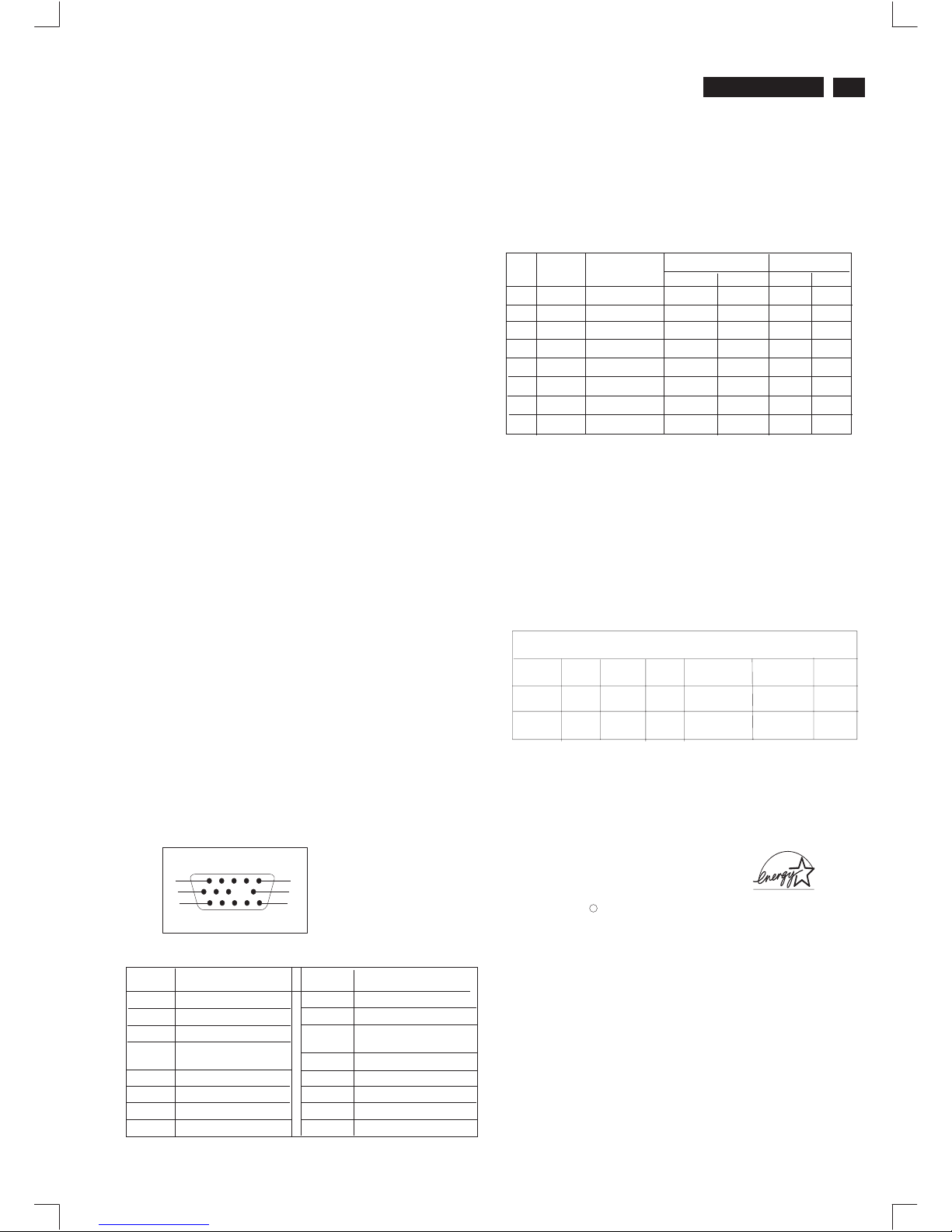
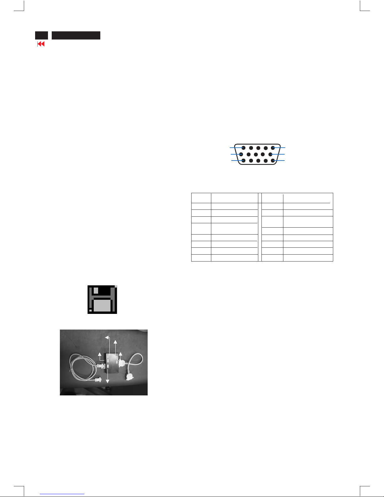
:The 15-pin D-sub connector(male) of the signal cable
Assignment
Assignment
Pin No.
Pin No.
Identical outputconnected to pin 10
Identical outputconnected to pin 10
Blue video input
2
7
6
8
4
5
3
1
9
12
11
14
13
15
10
Red video ground
Blue video ground
Green video ground
fground
No pin
Logic. Ground
Data clock line(SCL)
V.Sync(VCLK for DDC)
H.Sync /H + V
Serial data line(SDA)
Green video input
Red video input
Pin assignment :
H
V
-
-
-
-
-
+
+
+
+
+
+
+
+
+
+
+
V(Hz)
H(KHz)
Frequen
Sync polarity
Resolution
1024 x 768
1080 x 960
800 x 600
800 x 600
M02
M05
M06
M08
M07
M04
M03
M01
31.5
64.0
46.9
68.7
60.0
53.674
85
85
85
60
75
60
60
70
31.47
43.3
1280 x 1024
Mode
EVGA
EVGA
SVGA
SVGA
VGA
VGA
VGA
640 x 480
640 x 480
720 x 400
Power Management Definition
Active
Green
Flashing
Green
Blanked
97 %
0%
<2 w
Tyical 75 w
ON
OFF
No
No
Yes
Yes
V-SYNC
POWER
SAVING( % )
POWER
USED
LED
COLOR
H-SYNC
VIDEO
VESA's
mode
If you have VESA's DPMS compliance display card or software installed
in your PC, the monitor can automatically reduce power consumption
when power saving function active. And if an input from keyboard,
mouse or other input devices is detected, the monitor will automatically
"wake up". The following table shows the power consumption and
signaling of this automatic power saving feature :
Automatic Power Saving
Data Storage
Factory preset modes:
This monitor has 8 factory-preset modes as indicated in the
following table :
Technical Specification*
CRT
45%
Size and deflection :19 inch/46cm, 90
Dot pitch : 0.25 mm with black matrix
Horizontal pitch : 0.21 mm
Tube type : Shadow mask, real flat, high contrast,
anti-glare, anti-static,anti reflection,
light transmission
Phosphor : P22
Recommended display area : 14.0" x 10.4"/355 x 265 mm
Maximum display area
Scanning
Horizontal scanning : 30 - 97 KHz
Vertical : 50 - 160 Hz
Video
Video dot rate : 203 Mhz
Input impedance
-Video : 75 Ohms
- Sync : 2.2K Ohms
Signal input level : 0.7Vpp
Separate sync
o
deflection angle
: 14.4" x 10.8"/365 x 270 mm
scanning
Sync input signal : Composite sync.
Sync polarities : Positive or negative
White Color Temperature
Chromaticity CIE coordinates:
at 9300 k x = 0.283 +/- 0.015 y = 0.297 +/- 0.015
at 6500 k x = 0.313 +/- 0.015 y = 0.329 +/- 0.015
at 5500 k x = 0.332 +/- 0.015 y = 0.347 +/- 0.015
at sRGB x = 0.313 +/- 0.015 y = 0.329 +/- 0.015
Carton box
Size (with pedestal) : 440(W)x433(H)x449(D)
Net weight : 20 Kg
Power supply : 90 - 264 VAC, 50/60 Hz
Operating condition
Temperature : 0 C to 40 C
Relative Humidety : 10%-90%(W/O condensation)
Storage condition
Temperature : - 25 C to 65 C
Relative Humidity :5%to95%(W/O condensation)
o
o
o
00
OO
ENERGY STAR is a U.S. registered mark. AS AN ENERGY STAR
PARTNER, DELL Computer Corporation HAS DETERMINED THAT
THIS PRODUCT MEETS THE ENERGY STAR GUIDELINES FOR
ENERGY EFFICIENCY.
R
This monitor is ENERGY STAR compliant.
As an ENERGY STAR Partner, PHILIPS has determined that
this product meets the ENERGY STAR guidelines for energy
efficiency
1
10
6
11
15
5
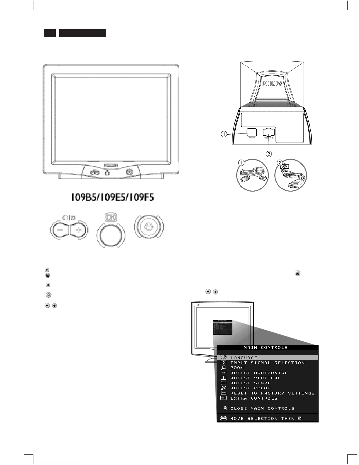
Front control & OSD
4
9
Go to cover page
V50 109B5
Description of the On Screen Display
What is the On-Screen Display?
Basic and simple instruction on the control keys.
This is a feature in all Philips monitors which allows an end-user to
adjust screen performance of monitors directly though an on-screen
instruction window. The user interface provides user-friendliness and
ease-of-use when operating the monitor.
On the front controls of your monitor, once you press the button, the
On Screen Display (OSD) Main Controls window will pop up and you
can now start making adjustments to your monitor's various features.
Use the the keys to make your adjustments within.
Rear view
1. Power in - attach power cable here.
2. Video In - this is a cable which is already attached to your monitor.
Connect the other end of the cable to your PC.
Front View
Power button switches your monitor on.
OK button which when pressed will take you to the OSD
controls
Contrast hotkey. When the "-" button is pressed,
the adjustment controls for the CONTRAST will show up.
Brightness hotkey. When the "+" button is pressed,
the adjustment controls for BRIGHTNESS will show up.
"-" and "+" buttons, are used for adjusting the OSD of your
monitor.
5
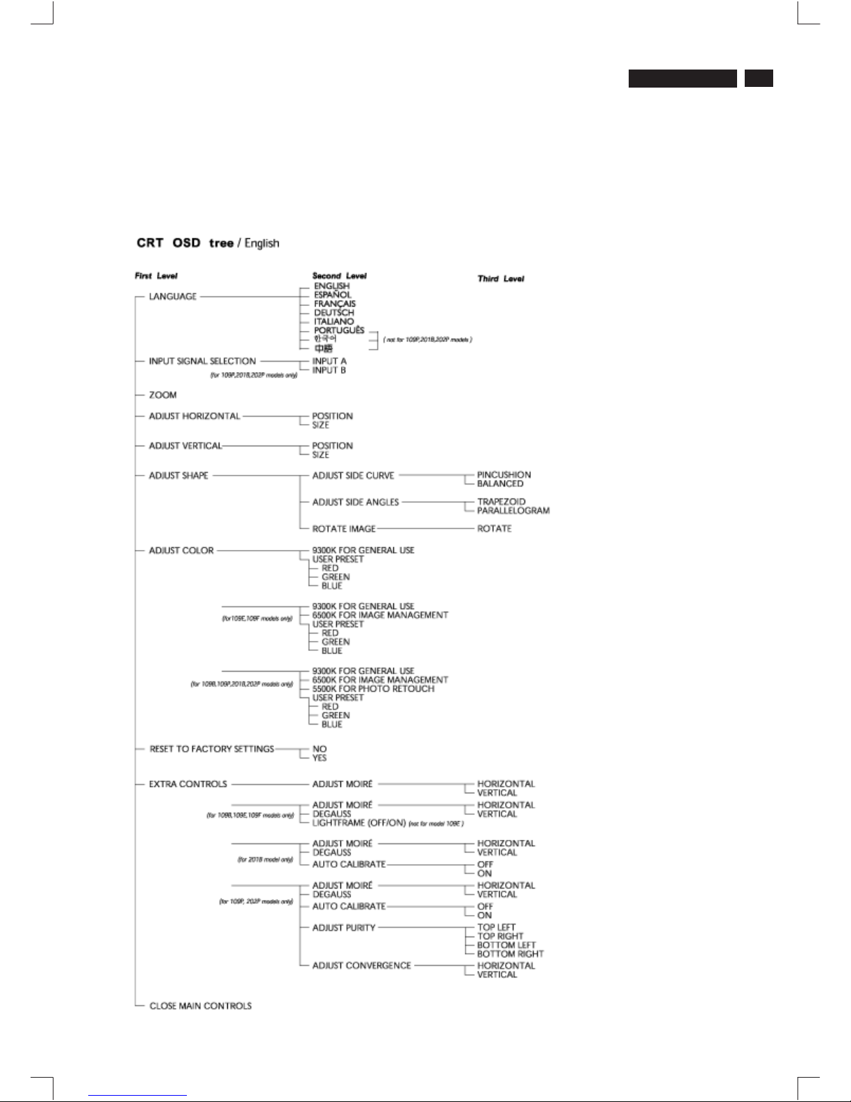
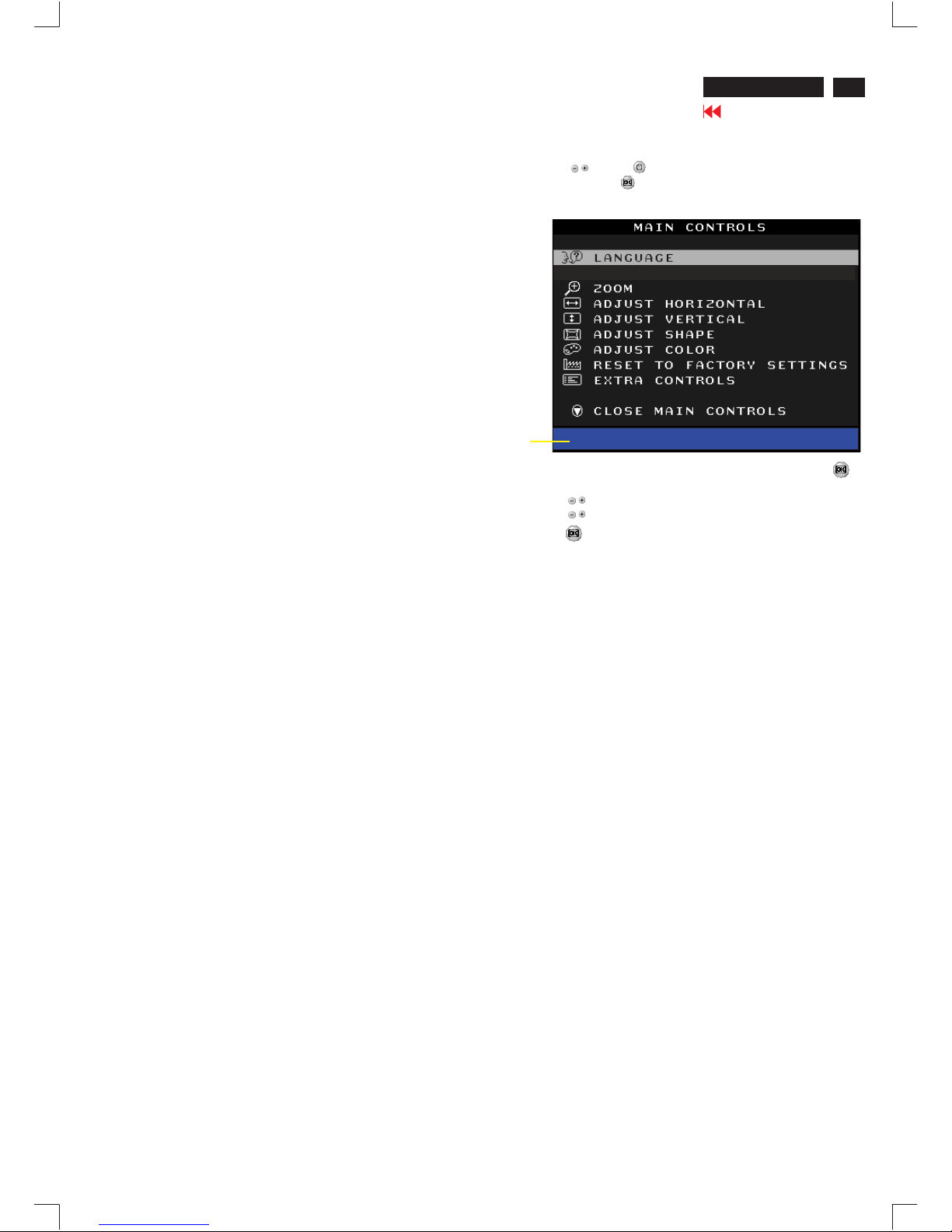
OSD menu tree
The OSD Tree
Below is an overall view of the structure of the On-Screen
Display. You can use this as reference when you want to
later on work your way around the different adjustments.
9
Go to cover page
V40 109F5
X
Go to cover page
6
V50 109B5
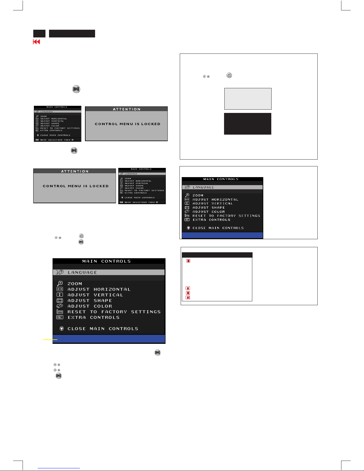
OSD Lock
Switch on OSD lock feature:
Switch off OSD lock feature:
OSD lock is a feature which disables the OSD controls. It can be used
when the monitor is set up for demonstration purposes or when
adjustment of the OSD is not desirable.
Press and hold the button continuously for 15 seconds.
Release the button when the message
"CONTROL MENU IS LOCKED" appears.
Press and hold the button continuously for 15 seconds or until the
message window "CONTROL MENU IS LOCKED" disappears, and
"MAIN CONTROLS" appears.
To access BURN IN mode
Reconnect the video cable, then return to normal image.
First of all, monitor displays an image.
1. Disconnect the video cable (interface cable).
2. Turn off monitor
3. Press '" " and " " simultaneously on the front control
panel,then the BURN IN mode comes on the screen of monitor
as below.
50 seconds around
5 seconds around
repeatly
4.
SERVICE MODE (Indication-Factory mode)
MODEL SELECT
00010
V50 109B5 97K V0.41 20030421
------------------------>
00010: stands for
1. using 10 hours already.
2. turn on/off 10 times.
3. using several hours
+ turn on/off monitor.
Default setting of MODEL SELECT (Do not change it.)
MODEL SELECT
V50 109B5 97K
RESERVE
RESERVE
RESERVE
RESERVE
RESERVE
SWDDC
LF ON OSD
LF 3
MODEL SELECT
V50 109B5 97K V0.41 20030421
Factory
Mode
Indicator
To access factory mode
1. Turn off monitor (don't turn off PC)
2. Press '" " and " " simultaneously on the front control
panel,then press " ",wait till the OSD menu with characters
V50 109B5 97K V0.41 20030421 (below OSD menu)" come on
the screen of monitor.
3. If OSD menu disappears on the screen of monitor, press " "
again (anytime), then the OSD menu comes on the screen again.
4. Using " " : to select OSD menu.
5. Using " " : to increase or decrease the setting.
6. Using " " to access/confirm the selection.
7. After alignment of factory mode, turn off monitor (if you do not turn
off monitor, the OSD menu is always at the factory mode), then
turn on monitor again (at this moment, the OSD menu goes back
to user mode).
To leave factory mode
Lock/Unlock, Factory Mode, Burn In, Service Mode
9
Go to cover page
7
V500 109B5
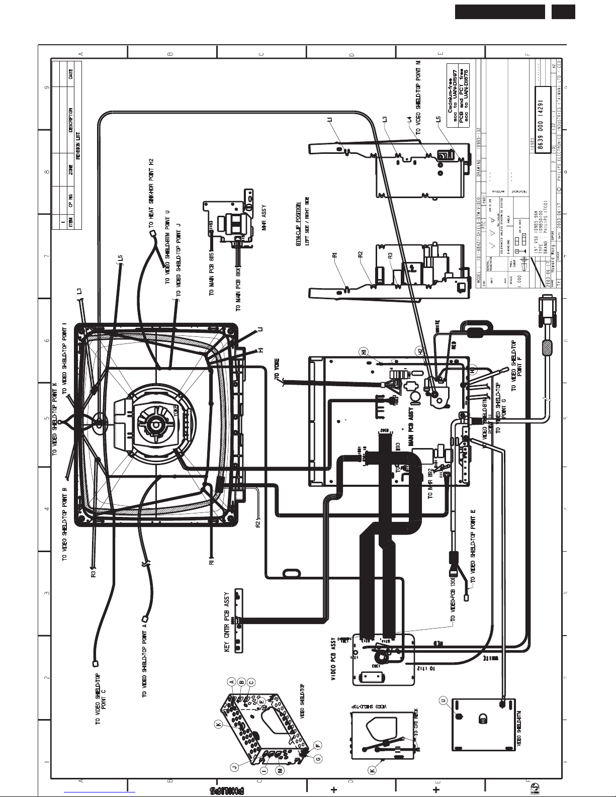
Wiring Diagram
Go to cover page
8
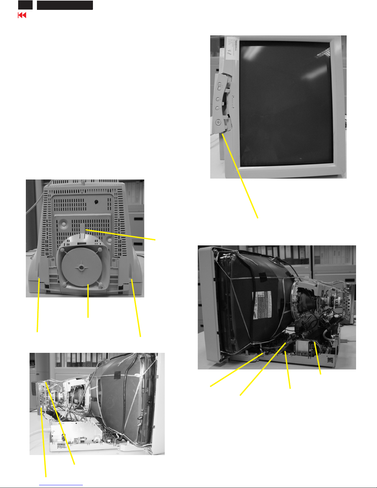
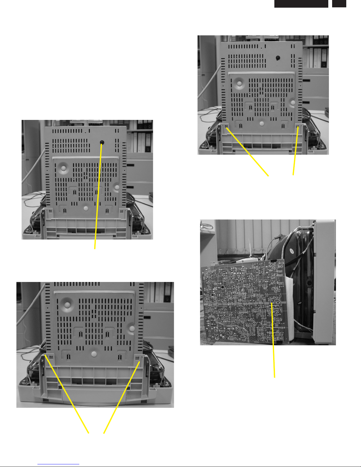
Mechanical Instructions
V50 109B5
0. General
2. Video panel
3.Main board connector in Fig. 4
To be able to perform measurements and repairs on the "circuit
boards", these unit should placed in the service position first.
-Remove 2 screws as shown
-Remove back cover as shown
-Remove pedestal as shown
-Disconnect york wire
-Disconnect rotation connector
-Disconnect control board connector
-Remove Screw for fixed I/F cable
-Remove signal connector
-Remove degaussing wire connector
1.Remove the rear cover in Fig. 1.
- Disconnect the wire between metal shield of Video panel and
CRT neck as shown in Fig. 2.
- Disconnect the CRT ground from Video panel.
- Remove screw grounding and grounding wire in Fig. 3.
Fig. 1
Screw
Screw
Pedestal ass'y
Video Panel
CRT grouding wirel
Fig. 2
Clip
Fig. 3
Fig. 4
Chin assy
Control connector
Signal connector
Degaussing wire connector
Rotation connector
9
Go to cover page
9
Mechanical Instructions
V50 109B5
4. Main panel with Bottom Tray
-Remove 2 screws for disconnect the Bottom tray as Fig. 5.
-Pull the bottom tray from fig. 6
to fig. 7.
on press right and left side clip
Reconnect connectors, some wires and panels (chassis),
service position can be available for DC/AC measurement
as shown in Fig. 8.
5. SERVICE POSITION
Fig. 6
Fig. 7
Fig. 5
Press CLIP
Screw
Press clip then Pull-up
=======>
Main panel
Fig. 8 SERVICE POSITION
X
Go to cover page
10
V50 109B5
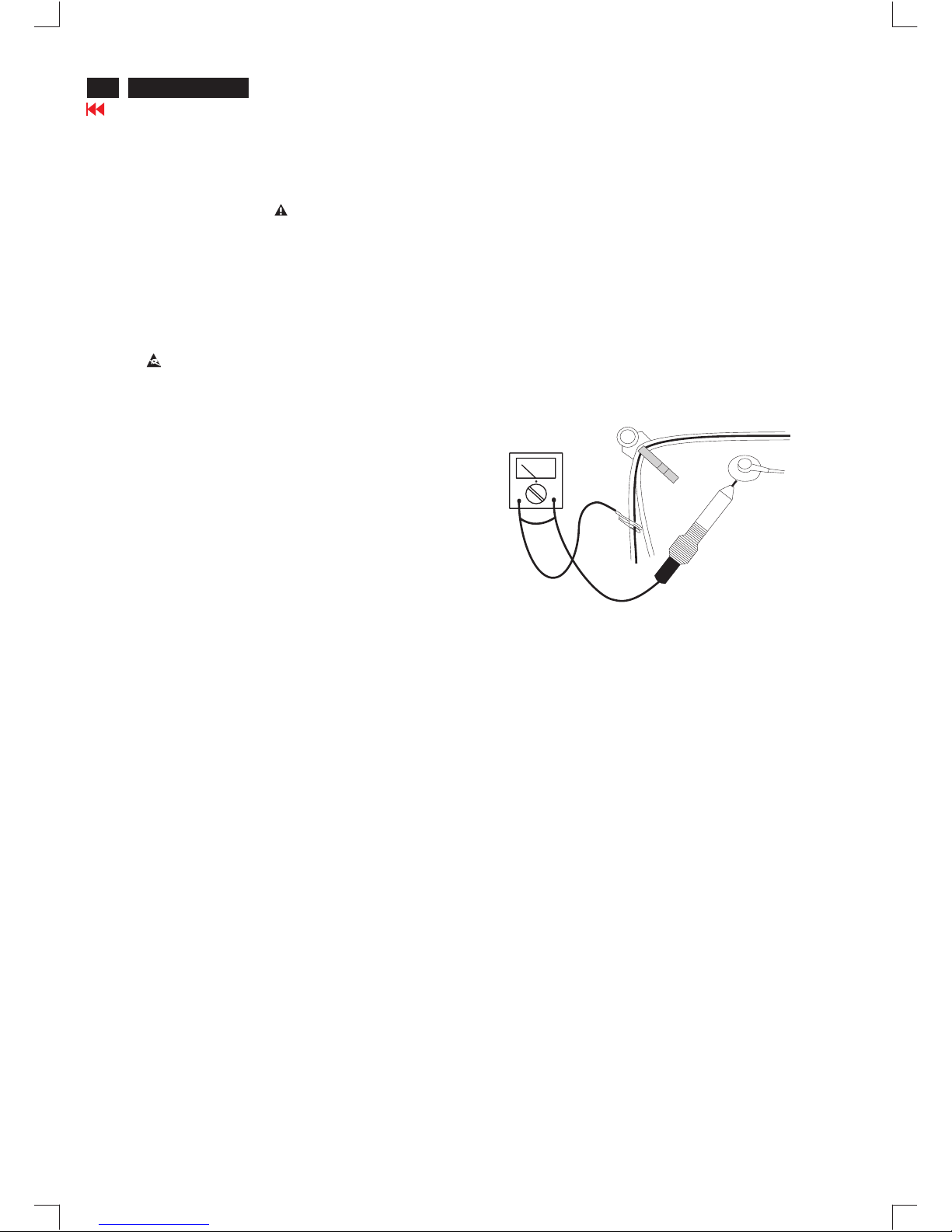
Warning and Notes
Fig.1
V
Warnings
1
2
0V
3 ESD
4
5
6
7
8
9
10.
11.
. Safety regulations require that the unit should be returned
in its original condition and that components identical to
the original components are used. The safety components
are indicated by the symbol .
. In order to prevent damage to ICs and transistors, all
high-voltage flash-overs must be avoided. In order to
prevent damage to the picture tube, the method shown
in Fig. 1 should be used to discharge the picture tube.
Use a high-voltage probe and a multimeter (position DC-V).
Discharge until the meter reading is (after approximately
30 seconds).
.
All ICs and many other semiconductors are sensitive to
electrostatic discharges (ESD). Careless handling during
repair can drastically shorten their life. Make sure that
during repair you are connected by a pulse band with
resistance to the same potential as the ground of the unit.
Keep components and tools also at this same potential.
. When repairing a unit, always connect it to the AC Power
voltage via an isolating transformer.
. Be careful when taking measurements in the high-voltage
section and on the picture tube panel.
. It is recommended that saferty goggles be worn when
replacing the picture tube.
. When making adjustments,use plastic rather than metal tools.
This will prevent any short-circuit or the danger of a
circuit becoming unstable.
. Never replace modules or other components while the
unit is switched on.
. Together with the defleciton unit, the picture tube is used
as an integrated unit. Adjustment of this unit during repair
is not recommended.
After repair, the wiring should be fastened in place with
the cable clamps.
All units that are returned for service or repair must pass
the original manufactures safety tests.
Notes
The direct voltages and waveforms are average voltages.
They have been measured using the Service test software
and under the following conditions :
- Mode : 640 * 480 (31.5kHz / 60Hz)
- Signal pattern : grey scale
- Adjust brightness and contrast control for the
mechanical mid-position (click position)
The picture tube panel has printed spark gaps.
Each spark gap is connected between an electrode of the
picture tube and the Aquadag coating.
The semiconductors indicated in the circuit diagram(s)
and in the parts lists are completely interchangeable per
position with the semiconductors in the unit, irrespective
of the type indication on these semiconductors.
1.
2.
3.
Electrical Adjustments
Go to cover page
11
V50 109B5
1. General
2.
3.0 Main chassis alignment
Input signal mode
Inspection modes : 8
Resolution modes H. freq. V. freq. H. V.
(Inspection timing)
1. 800 x 600 53.7 Khz 85 HZ(VESA) Don'tCare
2. 1024 x 768 60.0 Khz 75 HZ(VESA) Don't Care
3. 1024 x 768 68.7 Khz 85 HZ(VESA) Don't Care
5. 1280 x 1024 80.0 Khz 75 Hz (VESA Don't Care
7. 1280 x 1024 91.1 Khz 85 Hz (VESA) Don't Care
8. 1600 x 1200 93.8 Khz 75 Hz (VESA) Don't Care
3.1 Power supply adjustment
3.1.1 Set Vg2 manually (screen) to fully counterclockwise (zero
beam current).
3.1.2 Apply 80KHz/75Hz full black pattern.
3.1.3 Monitor the following auxiliary voltages.
3.2 High Tension Voltage (EHT) adjustment
3.2.1 Apply 68.7 KHz /85 Hz 1024x768 resolution signal.
Adjust manually (EHT) to obtain 26.00.3KV at CRT
anode at zero beam Current.
3.3 Check PF value with MHR function (option )
3.3.1 Apply 91kHz / 85Hz resolution with cross-hatch (contrast
Max. / brightness 50% ).
3.3.2 Apply input voltage 230VAC, input power consumption
about 55W 65W. The PF value about 0.7 0.8 (measure
equipment: AC Power Analyzer PM1200).
4. 1152 x 864 77.1 Khz 85 HZ(VESA) Don't Care
6. 1920 x 1440 90.0 Khz 60 Hz (VES) Don't Care
R3699
+197.0V source across C2152 and gnd +197.7V +/- 2.5 VDC
+ 82.5V source across C2151 + 80.5V +/- 2.0 VDC
+ 6.2V source across C2155 + 6.2V +/- 0.35 VDC
+ 12.4V source across C2153 +12.4V +/- 0.7 VDC
- 12.6V source across C2154 - 12.6V +/- 0.7 VDC
4. General conditions for alignment
4.1 During all alignments, supply a distortion free AC mains voltage
to set via an isolating transformer with low internal impedance.
4.2 Align in pre-warmed condition, at least 30 minutes warm-up with
nominal picture brightness.
4.3 Purity, geometry and subsequent alignments should be carried
out in magnetic cage with correct magnetic field.
Northern hemisphere : H=0, V= 430+/-50 mG, Z=0
Southern hemisphere : H=0, V=-520+/-50 mG, Z=0
4.4 All voltages are to be measured or applied with respect to ground.
4.5 Adjust brightness controls to center position except for contrast
control which should be set to MAX.
Note: Do not use heatsink as ground.
4.6 Any external voltage sources should have a low internal
impedance.
4.7 Adjust function controls to center position unless otherwise
stated.
4.8 The white balance and purity has to be adjusted in dully lighted
room.
4.9 All alignments have to be done in a room with a temperature of
25+/- 10 C.
0
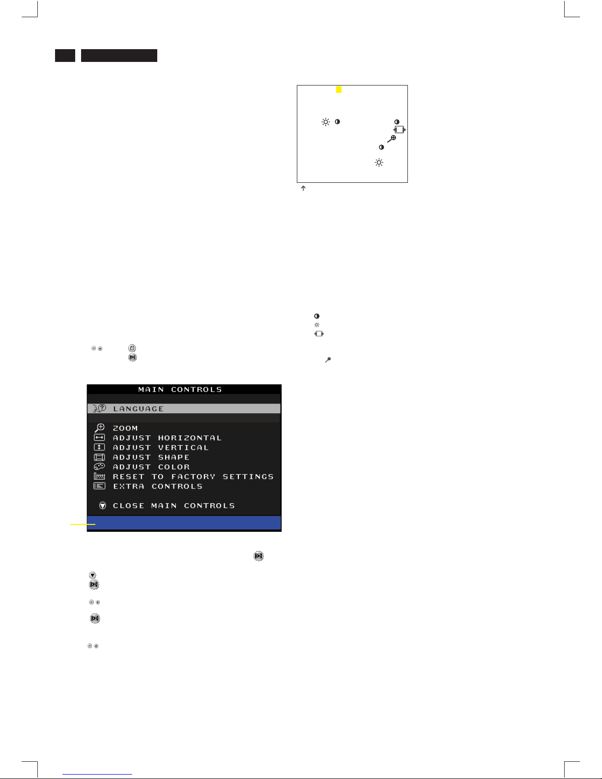
5. To access factory mode
To leave factory mode
5.1 Turn off monitor (don't turn off PC)
5.2 Press '" " and " " simultaneously on the front control
panel,then press " ",wait till the OSD menu with characters
V40 109F5 V0.45 20030410 (below OSD menu)" come on the
screen of monitor.
5.3 If OSD menu disappears on the screen of monitor, press " "
again (anytime), then the OSD menu comes on the screen again.
5.4 Using " " : to select OSD menu.
5.5 Using " " : to increase or decrease the setting.
5.6 Using " " to access/confirm the selection.
5.7 After alignment of factory mode, turn off monitor (if you do not
turn off monitor, the OSD menu is always at the factory mode),
then turn on monitor again (at this moment, the OSD menu goes
back to user mode).
MODEL SELECT
Factory
Mode
Indicator
V50 109B5 97K V0.41 20030421
6. Adjustment of the picture geometry
6.1.1 Apply Table 4 (79.976KHz/75.025Hz) without video signal, set
Brightness at 100%, set H-size V-size for raster size around
355x265 mm and set vertical position to 50%, Adjust Raster H
and Raster V centering for centered raster via I2C bus.
6.1.2 Adjust the Horizontal Size to 355mm.
6.1.3 Adjust the Horizontal Position to center position.
6.1.4 Adjust the Vertical Size to 265 mm.
6.1.5 Set Vertical Position = 50%, adjust the Raster V for correctly
centered vertical video.
6.1.6 Adjust picture tilt ( Rotate ) for correct TOP/BOTTOM lines.
(Picture tube should be mounted without tilt w.r.t. Cabinet)
6.1.7 Adjust pincushion to get optimum vertical line.
6.1.8 Adjust trapezoid to get optimum vertical line.
6.1.9 Adjust balanced pincushion to get optimum vertical line.
6.1.10Adjust the parallelogram to get optimum vertical line.
6.1.11Adjust the Top/Bottom corner control to get optimum corner
geometry.(6.1.6, 6.1.7, 6.1.8 and 6.1.9 may need to be readjusted)
6.1.12 Store the set result and exit OSD.
(the values for pincushion, trapezoid, balance pincushion and
parallelogram can be copied to the other inspection modes to
shorten alignment time)
6.2 Other inspection mode geometry adjustment
Use following procedure for all inspection modes (except
68.7kHz/85Hz)(Timing Table1-8)
6.2.1 Adjust the Horizontal Size to 355mm.
6.2.2 Adjust the Horizontal Position to center position.
6.2.3 Adjust the Vertical Size to 265 mm.
6.2.4 Adjust the Vertical Position for correctly centered vertical video.
6.2.5 Adjust pincushion to get optimum vertical line.
6.2.6 Adjust trapezoid to get optimum vertical line.
6.2.7 Adjust balanced pincushion to get optimum vertical line.
6.2.8 Adjust the parallelogram to get optimum vertical line.
(6.2.5, 6.2.6, 6.2.7 and 6.2.8 may need some iteration)
6.2.9 Store the set result and exit OSD.
Electrical Adjustments (Continued)
9
Go to cover page
12
V50 109B5
BIASRGB:R(red) G(green) B(blue) cutoff
GAINRGB:R(red) G(green) B(blue) gain
OSD contrast : OSD window contrast
V OFFSET : Vertical raster center
V GAIN : Vertical size center
VLIN BAL : Vertical Linearity Balance
V FOCUS : Vertical Focus adiustment
T CORNER: Corner Correctionof TOP
B CORNER: Corner Correctionof BOTTOM
EHT H : Horizontal Size compensation
ABL : Auto brightness Limitation
SUB : Sub Contrast allowance range
SUB : Sub Brigntness allowance range
SUB : Horizontal size range adjustment range
HLIN : Horizontal Linearity
V LIN : Vertical Linearity
RANGE : Zoom range
7.2 Setup A, manually increase Vg2 voltage until brightest
color reaches 100 scale
7.3 Setup A, adjust R/G/B cut-off (I C) for all colors at 100 +/-
7Scale
7.4 Setup B, adjust sub-contrast (I C) for RGB readings around
100, then adjust RGB gain for all colors at 100 +/- 2 scale.
7.5 Repeat 5.3.2, 5.3.3 (RGB cut-off and gain) to get both low and
high 9300 scales at 100(0.10FL+/- 0.05FL for low scaale;
for high scale. x/y tolerance +/-0.005)
7.6 Setup C, adjust R/G/B cut-off (I C) for all colors at 100 +/7 scale
7.7 Setup D, adjust RGB gain for all colors at 100 +/- 2 scale.
7.8 Repeat 5.3.5, 5.3.6 (RGB cut-off and gain) to get both low and
high 6500 scales at 100 (0.10FL+/-0.05FL for low scale,
for high scale. x/y tolerance+/- 0.005)
7.9 Setup E, adjust R/G/B cut-off (I C) for all colors at 100 +/7 scale
7.10 Setup F, adjust RGB gain for all colors at 100 +/- 2 scale.
7.11 Repeat 5.3.8, 5.3.9 (RGB cut-off and gain) to get both low
and high 5500 scales at 100 (0.10FL+/-0.05FL for low scale,
for high scale. x/y tolerance +/-0.005)
7.12 Setup G, Adjust ABL (I C) for 30FL+/- 0.5FL
7.13 Apply full white pattern, sRGB: sRGB cutoff and gain are
same as 6500 color temperature. Setting brightness at 50%,
then set sRGB contrast at 23 +/- 1 FL.
2
2
2
2
2
41FL+/- 1FL
35FL+/-1FL
32FL+/-1FL
(for ref. 75,107,116,218,174,161)
(for ref. 80,110,117,206,141,93)
(for ref. 86,112,118,206,121,56)
(for ref. 89,115,124,145,85,40)
(for ref. 128,255,180)
(for ref. 0,140,100,50)
(for ref. 79,127,255,120,50)
(for ref. 128,220,184)
(for ref. 220)
(for ref. 35,50,88,255)
(for ref. 3,3)
Fig. 2.2
(for example: 75 is value of "BIAS R")
7. Alignment of Vg2 cut-off point, white tracking
Equipment : 1. Video Test Generator-801GC (Quantum Data)
2. Color-analyzer (Minolta CA-100)
Adjustment mode: 68.67KHz/85Hz with correctly adjusted
video size 355x265mm Use color-analyzer (Minolta CA-100) to
adjust cut-off and white balance.Before alignment, set initial
data as below (all values show on factory OSD):
Brightness=50%, Sub-Contrast=85%, ABL=70% (I C)
9300K
R cut-off = %, R gain = 65% (I C)
G cut-off = % , G gain = 55% (I C)
B cut-off = %, B gain = 65% (I C)
6500K
R cut-off = %,Rgain=55%(I C)
G cut-off = %, G gain = 65% (I C)
B cut-off = % , B gain = 55% (I C)
5500K
R cut-off = %, R gain = 55% (I C)
G cut-off = %, G gain = 55% (I C)
B cut-off = %, B gain = 55% (I C)
Vg2 (screen) to fully counterclockwise (zero beam
current).(Manual)
2
2
2
2
2
2
2
2
2
2
40
40
40
40
40
40
40
40
40
Setting RGB cut-off = 50% at 9300K,6500K,5500K only for SDI
tube.
Step 1: To access factory mode
- Turn off monitor (don't turn off PC)
- Press " " and " " simultaneously on the front control
panel,then press " ",wait till the OSD menu with characters
V40 109S5 V0.45 20030410 (below OSD menu)" comes on the
screen of monitor as shown in Fig. 2.1.
- If OSD menu disappears on the screen of monitor, press " "
again (anytime), then the OSD menu comes on the screen again.
- Using " " to select .
- Using " " : to increase or decrease the value.
V50 109B5 97K V0.41 20030421
- Press " " button to access/confirm the selection.
Bring up the "function adjustment" as shown in Fig. 2.2.
- Press '" " button for function selection as shown in
Fig. 2.2.
- Press " " button to access/confirm each item selection
(The cursor indicator will be changed from yellow colour to
red colour.)
MODEL SELECT
Factory
Mode
Indicator
Fig. 2.1
9300 BIAS R G B GAINRGB
6500 BIAS R G B GAINRGB
5500 BIAS R G B GAINRGB
SRGB BIAS R G B GAINRGB
SRGB ( ) OSD
FOCUS(H V) VLINBAL USER
RASTER (H V) LIN(H V) SUB
V(OFFSET GAIN) SUB
SUB VPOSITION
CORNER(T B) ABL SUB
LF(BRIGH SHARP)
EXIT
131
V50 109B5 97K V0.41 20030421

Electrical Adjustments (Continued)
8. Focus adjustment
9. Loading DDC code
The DDC HEX data should be written into the EEPROM
(7802) by EDID301.EXE Program(3138 106 10103)
and software DDC Alignment kits (4822 310 11184).
With display at timing ,
each block is a square of . Set brightness at 50%
and at the center of the screen. and adjust focus
pot-meter which is located at fly-back transformer, until the haze
just disappears on 2/3 east and west, top and down of the screen.
- Make sure the monitor is not exposed to any
external magnetic field.
- Produce a full red pattern on the screen, adjust the
purity magnet rings on the PCM assy (on CRT) to
obtain a complete field of the color red. This is done
by moving the two tabs (2-pole) in such a manner
that they advance in an opposite direction but at
the same time to obtain the same angle between
the two tabs, which should be approximately 180
degree.
- Check by full green pattern and full blue pattern
again to observe their respective color purity.
Introduction
Slight deviation in the static convergence can be
corrected by using two permanent pairs of magnets
which are fitted around the neck of the CRT. These
are the 4-pole magnet and the 6-pole magnet.
The 4-pole magnet move the outermost electron
beams (R and B) parallel in the opposite direction
from the other. The 6-pole magnet moves the
outermost electron beam (R, B and G) parallel in the
opposite direction from the other.
The magnetic field of the above magnets do not affect
the center of the CRT neck.
Setting
- Before the static convergence setting can be made,
the monitor must be switched on for 30 minutes.
- The focus setting must be made correctly.
- Signal: 640 * 480, 31.5 kHz/60 Hz mode.
- Set the tabs of the 4-pole magnet in the neutral
position. This is when the tabs are opposite one
another. In this position the magnets do not affect the
deflection of the R and B electron beams.
- Set the tabs of the 6-pole magnet in the neutral
position. This is when the tabs are opposite one
another. In this position the magnets do not affect the
deflection of the R, B, and G electron beams.
- First set the 4-pole magnet optimally.
- Then set the 6-pole magnet optimally.
- If the convergence is not now optimal, then adjust to
the optimal setting with the 4-pole magnet and then with
the 6- Pole magnet again.
- Set the tabs of the 6-pole magnet in the neutral
position. This is when the tabs are opposite one
another. In this position the magnets do not affect the
deflection of the R, B, and G electron beams.
- First set the 4-pole magnet optimally.
- Then set the 6-pole magnet optimally.
- If the convergence is not now optimal, then adjust to
the optimal setting with the 4-pole magnet and then
with the 6- pole magnet again.
10. Purity adjustment
11. Static convergence
9-blocks ME pattern 79.9KHz 1280 X 1024
90mm x 90mm
contrast at 100%
2-pole purity magnet
6-pole convergence magnet
4-pole convergence magnet
Deflection Yoke
4-pole Beam motion producced by the
4-pole convergence magnet
S
S
N
N
B
G R
S
S
N
N
B
G
R
Beam displacement
direction
Magnetic flux
lines
6-pole
Beam motion producced by the
6- pole convergence magnet
S
S
S
N
N
N
R
B
G
S
S
S
N
N
N
R
B
G
Go to cover page
13
V50 109B5
Go to cover page
DDC Instructions
14
V50 109B5
1. General
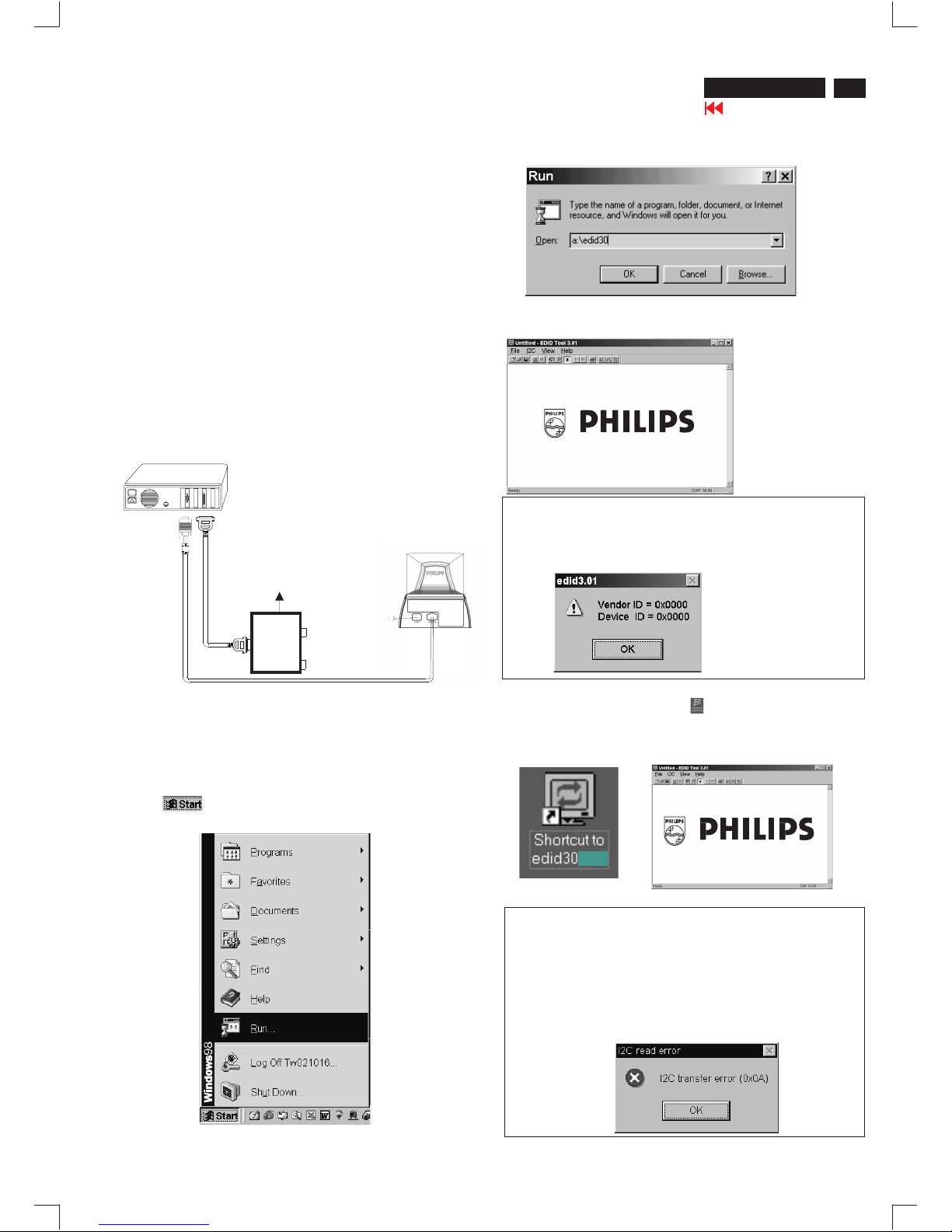
3. Pin assignment
Fig. 2 Alignment Kits
To Monitor
DC 8V~12V
Video Card
Video Card
To Printer
Power indicator
A. 15-pin D-Sub Connector
DDC Data Re-programming
In case the main EEPROM with Software DDC which store all factory
settings were replaced because a defect,repaired monitor the serial
numbers have to be re-programmed.
It is advised to re-soldered the main EEPROM with Software DDC from
the old board onto the new board if circuit board have been replaced, in
this case the DDC data does not need to be re-programmed.
Additional information
Additional information about DDC (Display Data Channel) may be
obtained from Video Electronics Standards Association (VESA).
Extended Display Identification Data(EDID) information may be also
obtained from VESA.
DDC EDID structure
For the monitor : Standard Version 3.0
Structure Version 1.2
1. An i486 (or above) personal computer or compatible.
2. Microsoft operation system Windows 95/98.
3. EDID301.EXE program (3138 106 10103) shown as Fig. 1
4. Software DDC Alignment kits (4822 310 11184) shown as Fig. 2.
The kit contents: a. Alignment box x1
b. Printer cable x1
c. D-Sub cable x1
Note: The EDID301.EXE (Release Version 1.58, 20000818)is a
windows-based program, which cannot be run in MS-DOS.
2. System and equipment requirements
Diskette with EDID301.EXE
EDID301.EXE
Figure 1
Ver:1.58
The 15-pin D-sub connector (male) of the signal cable
on the 3rd row for DDC feature :
1
10
6
11
15
5
Assignment
Assignment
Pin No.
Pin No.
Ground
Ground
Blue video input
2
7
6
8
4
5
3
1
9
12
11
14
13
15
10
Red video ground
Blue video ground
Green video ground
for selftest(PC ground)
DDC 5V
Sync. Ground
Data clock line(SCL)
V.Sync(VCLK)
H.Sync
Bi-directional data(SDA)
Green video input
Red video input
X
Go to cover page
15
DDC Instructions (Continued)
V50 109B5
4. Configuration and procedure
There is no Hardware DDC (DDC IC) anymore. Main EEPROM stores
all factory settings and DDC data (EDID code) which is so called
Software DDC. The following section describes the connection and
procedure for Software DDC application. The main EEPROM can be reprobrammed by enabling "factory memory data write" function on the
DDC program (EDID301.EXE).
Step 3: Installation of EDID301.EXE
Method 1: Start on DDC program
Start Microsoft Windows.
1. Insert the disk containing EDID301.EXE program into floppy disk
drive.
2. Click , choose Run at start menu of Windows 95/98 as
shown in Fig. 4.
Fig. 4
*** INITIALIZE ALIGNMENT BOX ***
In order to avoid that monitor entering power saving mode due to
sync will cut off by alignment box, it is necessary to initialize
alignment box before re-programming DDC Data. Following steps
show you the procedures and connection.
Step 1
Step 2
: Supply 8~12V DC power source to the Alignment box by
plugging a DC power cord or using batteries.
: Connecting printer cable and video cable of monitor as
shown in Fig.3.
4. Click button. The main menu appears (as shown in Fig. 6).OK
This is for initialize alignment box.
Fig. 6
Fig. 5
Fig. 7
Note 1: If the connection is improper, you will see the following error
message (as shown in Fig. 7) before entering the main menu.
Meanwhile, the (read EDID) function will be disable. At this time,
please make sure all cables are connected correctly and fixedly,
and the procedure has been performed properly.
3. At the submenu, type the letter of your computer's floppy disk drive
followed by :EDID301 (for example, A:\EDID301, as shown in Fig. 5).
Method 2: After create a shortcut of EDID301.EXE
This is for initialize alignment box.
: Double click EDID301 icon (as shown in Fig. 8) which is
on the screen of Windows Wallpaper.
Bring up main menu of EDID301 as shown in Fig. 9.
Fig. 9
Note 2: During the loading, EDID301 will verify the EDID data which just
loaded from monitor before proceed any further function, once
the data structure of EDID can not be recognized, the following
error message will appear on the screen as below. Please
confirm following steps to avoid this message.
1. The data structure of EDID was incorrect.
2. DDC IC that you are trying to load data is empty.
3. Wrong communication channel has set at configuration setup
windows.
4. Cables loosed or poor contact of connection.
Fig. 8
1
Fig. 3
Rear view of the monitor
~
~
PC
To printer port (LTP1)
DC Power
8~12 V
Printer
Port
To video card
To
Monitor
To P C
Video cable
DDC Instructions (Continued)
Go to cover page
16
V50 109B5
Fig. 13
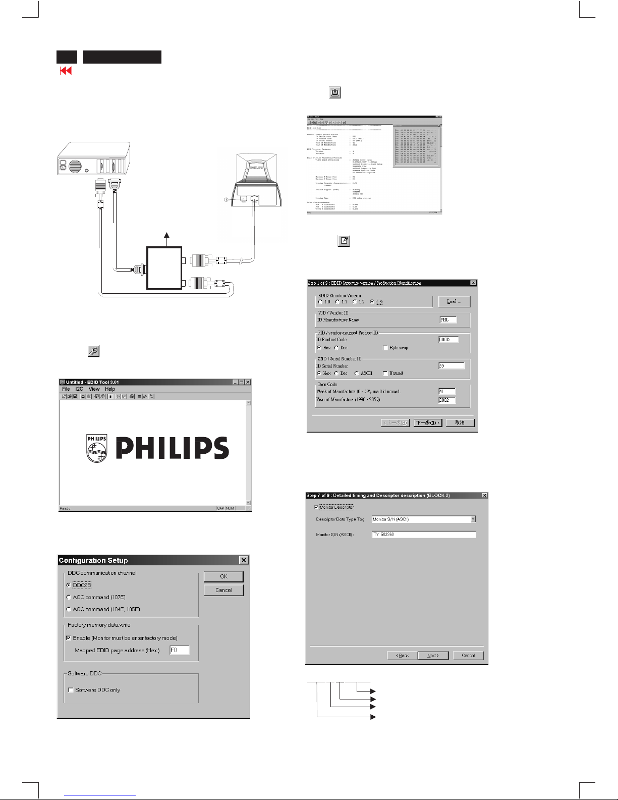
Re-programming EEPROM (Software DDC)
Step 1: After initialize alignment box, connecting all cables and
box as shown in Fig. 10
Fig. 11
Fig. 12
Step 2: Read DDC data from monitor
1-1 Click the left key of Mouse, or hit any key on the keyboard,
then the characters disappear from the screen.
1-2 Click icon as shown if Fig. 11 from the tool bar to bring up
the "Configuration Setup" windows as shown in Fig. 12.
2. Select the DDC2B as the communication channel.
Select " " & fill out " " for Mapped EDID page address
as shown in Fig. 12.
Enable F0
Step 3: Modify DDC data (verify EDID version, week, year)
1. Click (new function) icon from the tool bar, bring up
Step 1 of 9 as shown in Fig. 14 .
EDID301 DDC application provides the function selection and
text change (select & fill out) from Step 1 to Step 9.
Step 4: Modify DDC data (Monitor Serial No.)
Next
Next Finish
1. Click till the Step 7 of 9 window appears as shown in Fig. 15.
2. Fill out the new Serial No. (for example, TY 503960, TY 123456).
3. Click till the last step window appears, then click to exit
the Step window.
3. Click OK button to confirm your selection.
4. Click icon (Read EDID function) to read DDC EDID data from
monitor. The EDID codes will display on screen as shown in Fig. 13.
Fig. 14
Fig. 15
~
~
PC
To video card
To printer port (LTP1)
DC Power
8~12 V
Printer
Port
To
Monitor
To P C
Video cable
Fig. 10
Rear view of the monitor
Definition of Serial Number (barcode format)
TY00 03 15000001
Serial Number (U.S.A: 8 digit)
Week
Year
TY Code
TY----Chungli
CX----Dong Guan
HD----Hungary
BZ----Suzhou
(Others regions: 6 digit)
two space
(for example: change it from TY 503960
to TY 123456)
------>
DDC Instructions (Continued)
Go to cover page
17
V50 109B5
Fig. 16
Fig. 18
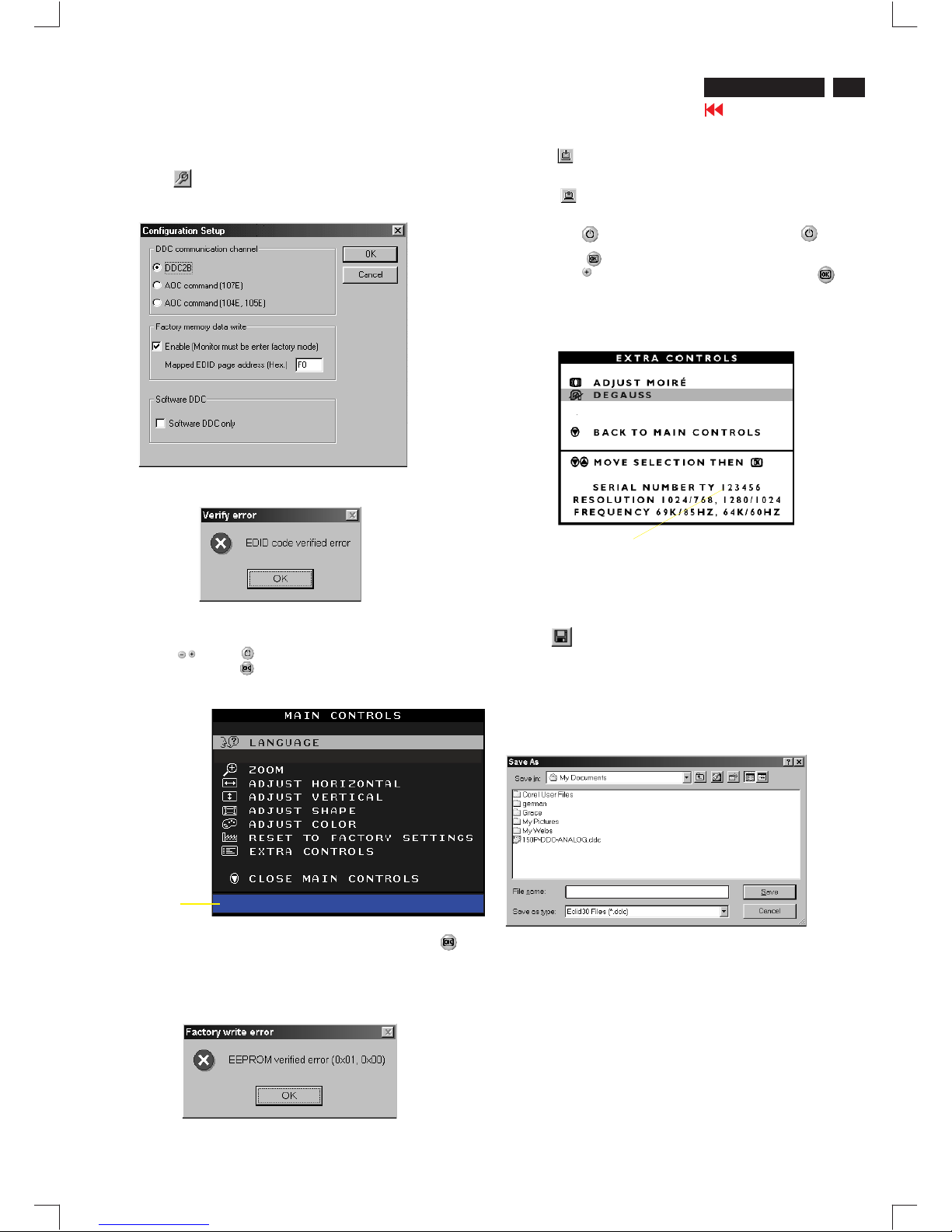
Step 8: Save DDC data
Sometimes, you may need to save DDC data as a text file for using
in other IC chip. To save DDC data, follow the steps below:
1. Click (Save) icon (or click "file"-> "save as") from the tool bar
and give a file name as shown in Fig. 19.
The file type is EDID301 file (*.ddc) which can be open in WordPad.
By using WordPad, the texts of DDC data & table (128 bytes, hex
code) can be modified. If DDC TEXTS & HEX Table are completely
correct, it can be saved as .ddc flie to re-load it into EEPROM for
DDC Data application.
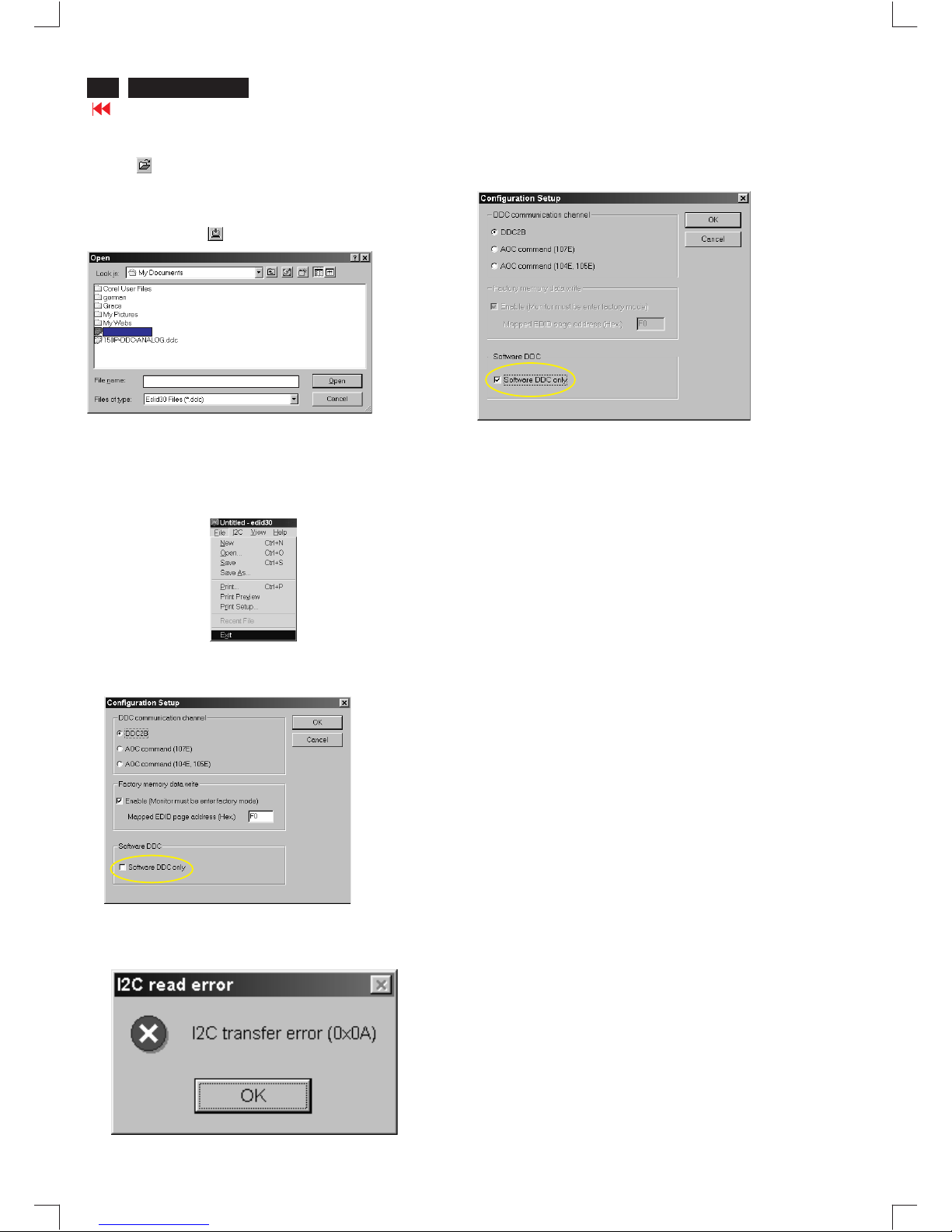
Step 5: **Configuration Setup & Enter Factory Mode **
for "write EDID data"
1. Click icon from the tool bar to bring up the Configuration Setup
windows again. Then, select "Software DDC only" as shown in
Fig. 16. Click "OK".
Step 6: Write DDC data
1. Click (Write EDID) icon from the tool bar to write DDC data.
Bring up "Writing 0%~100%, ready" a progressing bar on the left
down corner.
2. Click (Read EDID) to confirm it.
Step 7: Confirm Serial Number in User Mode
1. Press the button to turn off the monitor. Press the button
again to turn on the monitor.
2. Press the button to bring up the OSD Main Menu.
3. Press the button to select Extra Controls, press the
button to confirm your selection.
4. Confirm the Serial Number "123456" is updated
as shown in Fig. 18.
Fig. 19
If you do not select "Software DDC only", when you execute
"write EDID", it will bring up an error message as below.
If you do not access "Factory mode", when you execute
"write EDID", it will bring up an error message as below.
To access factory mode
1. Turn off monitor (don't turn off PC)
2. Press " " and " " simultaneously on the front control
panel,then press " ",wait till the OSD menu with characters
V5040 109B5 97K V0.41 20030421 (below OSD menu)" come on
the screen of monitor.
If OSD menu disappears on the screen of monitor, press " "
again (anytime), then the OSD menu comes on the screen again.
Fig. 17
MODEL SELECT
V50 109B5 97K V0.41 20030421
Factory
Mode
Indicator
2. Click .Save
109B5 V50
DDC Instructions (Continued)
Go to cover page
18
Fig. 20
Fig. 22
Fig. 23
Fig. 21
Step 10: Exit DDC program
Pull down the File menu and select Exit as shown in Fig. 21.
(EDID Tool 3.01)
Step 9: Load DDC data
Open
1. Click from the tool bar.
2. Select the file you want to open as shown in Fig. 20.
3. Click .
4. Access "Factory Mode" and enable "Software DDC only" as shown
in Fig. 17 & Fig. 16.
5. Write EDID (click ).
Note1 : In User Mode: Read DDC data only
Software
DDC only was disabled
Before read EDID code, please confirm that the
as shown in Fig. 22.
Note2:InFactory Mode: Read/Write DDC data
Software DDC only was enabled
Before Read/Write EDID code, please confirm that the
as shown in Fig. 23.
If you do not disable "Software DDC only", when you execute
"read EDID", it will bring up an error message as below.
109B5 V50.DDC
109B5 V50.DDC
V50 109B5

19
Go to cover page
V50 109B5
Hex Data of DDC2B
**********************************************************************
EDID log file for SDI tube
**********************************************************************
Vendor/Product Identification
ID Manufacturer Name : PHL
ID Product Code : E018 (HEX.)
ID Serial Number : 12345 (DEC.)
Week of Manufacture : 33
Year of Manufacture : 2003
EDID Version, Revision
Version : 1
Revision : 3
Basic Display Parameters/Features
Video Input Definition : Analog Video Input
0.700V/0.000V (0.70Vpp)
without Blank-to-Black Setup
Separate Sync
without Composite Sync
without Sync on Green
no Serration required
Maximum H Image Size : 36
Maximum V Image Size : 27
Display Transfer Characteristic : 2.9
(gamma)
Feature Support (DPMS) : Standby
Suspend
Active Off
Display Type : RGB color display
Standard Default Color Space : Primary color space
Preferred Timing Mode : Detailed timing block 1
Color Characteristics
Red X coordinate : 0.639
Red Y coordinate : 0.323
Green X coordinate : 0.275
Green Y coordinate : 0.597
Blue X coordinate : 0.143
Blue Y coordinate : 0.062
White X coordinate : 0.283
White Y coordinate : 0.297
Established Timings
Established Timings I : 720 x 400 @70Hz (IBM,VGA)
720 x 400 @88Hz (IBM,XGA2)
640 x 480 @60Hz (IBM,VGA)
640 x 480 @67Hz (Apple,Mac II)
640 x 480 @72Hz (VESA)
640 x 480 @75Hz (VESA)
800 x 600 @56Hz (VESA)
800 x 600 @60Hz (VESA)
Established Timings II : 800 x 600 @72Hz (VESA)
800 x 600 @75Hz (VESA)
832 x 624 @75Hz (Apple,Mac II)
1024 x 768 @87Hz (IBM)
1024 x 768 @60Hz (VESA)
1024 x 768 @70Hz (VESA)
1024 x 768 @75Hz (VESA)
1280 x 1024 @75Hz (VESA)
Manufacturer's timings : 1152 x 870 @75Hz (Apple,Mac II)
Standard Timing Identification #1
Horizontal active pixels : 640
Aspect Ratio : 4:3
Refresh Rate : 85
Standard Timing Identification #2
Horizontal active pixels : 800
Aspect Ratio : 4:3
Refresh Rate : 85
Standard Timing Identification #3
Horizontal active pixels : 1024
Aspect Ratio : 4:3
Refresh Rate : 85
Standard Timing Identification #4
Horizontal active pixels : 1280
Aspect Ratio : 5:4
Refresh Rate : 85
Standard Timing Identification #5
Horizontal active pixels : 1600
Aspect Ratio : 4:3
Refresh Rate : 75
Standard Timing Identification #6
Horizontal active pixels : 1920
Aspect Ratio : 4:3
Refresh Rate : 60
Detailed Timing #1
Pixel Clock (MHz) : 202.5
H Active (pixels) : 1600
H Blanking (pixels) : 560
V Active (lines) : 1200
V Blanking (lines) : 50
H Sync Offset (F Porch) (pixels): 64
H Sync Pulse Width (pixels): 192
V Sync Offset (F Porch) (lines) : 1
V Sync Pulse Width (lines): 3
H Image Size (mm) : 360
V Image Size (mm) : 270
H Border (pixels) : 0
V Border (lines) : 0
Flags : Non-interlaced
: Normal Display, No stereo
: Digital Separate sync.
: Positive Vertical Sync.
: Positive Horizontal Sync.
Monitor Descriptor #2
Serial Number : TY 123456
Monitor Descriptor #3
Monitor Name : PHILIPS 109B5
Monitor Descriptor #4
Monitor Range Limits
Min. Vt rate Hz : 50
Max. Vt rate Hz : 160
Min. Horiz. rate kHz : 30
Max. Horiz. rate kHz : 97
Max. Supported Pixel : 240
No secondary GTF timing formula supported.
Extension Flag : 0
Check sum : 49 (HEX.)
**********************************************************************
EDID data (128 bytes)
**********************************************************************
0: 00 1: ff 2: ff 3: ff 4: ff 5: ff 6: ff 7: 00
8: 41 9: 0c 10: 18 11: e0 12: 39 13: 30 14: 00 15: 00
16: 21 17: 0d 18: 01 19: 03 20: 68 21: 24 22: 1b 23: be
24: ee 25: bb 26: b8 27: a3 28: 52 29: 46 30: 98 31: 24
32: 0f 33: 48 34: 4c 35: ff 36: ff 37: 80 38: 31 39: 59
40: 45 41: 59 42: 61 43: 59 44: 81 45: 99 46: a9 47: 4f
48: d1 49: 40 50: 01 51: 01 52: 01 53: 01 54: 1a 55: 4f
56: 40 57: 30 58: 62 59: b0 60: 32 61: 40 62: 40 63: c0
64: 13 65: 00 66: 68 67: 0e 68: 11 69: 00 70: 00 71: 1e
72: 00 73: 00 74: 00 75: ff 76: 00 77: 20 78: 54 79: 59
80: 20 81: 20 82: 31 83: 32 84: 33 85: 34 86: 35 87: 36
88: 0a 89: 20 90: 00 91: 00 92: 00 93: fc 94: 00 95: 50
96: 48 97: 49 98: 4c 99: 49 100: 50 101: 53 102: 20 103: 31
104: 30 105: 39 106: 42 107: 35 108: 00 109: 00 110: 00 111: fd
112: 00 113: 32 114: a0 115: 1e 116: 61 117: 18 118: 00 119: 0a
120: 20 121: 20 122: 20 123: 20 124: 20 125: 20 126: 00 127: 49

Go to cover page
Hex Data of DDC2B
20
V50 109B5
**********************************************************************
EDID log file LG
**********************************************************************
Vendor/Product Identification
ID Manufacturer Name : PHL
ID Product Code : E018 (HEX.)
ID Serial Number : 12345 (DEC.)
Week of Manufacture : 33
Year of Manufacture : 2003
EDID Version, Revision
Version : 1
Revision : 3
Basic Display Parameters/Features
Video Input Definition : Analog Video Input
0.700V/0.000V (0.70Vpp)
without Blank-to-Black Setup
Separate Sync
without Composite Sync
without Sync on Green
no Serration required
Maximum H Image Size : 36
Maximum V Image Size : 27
Display Transfer Characteristic : 3.03
(gamma)
Feature Support (DPMS) : Standby
Suspend
Active Off
Display Type : RGB color display
Standard Default Color Space: Primary color space
Preferred Timing Mode : Detailed timing block 1
Color Characteristics
Red X coordinate : 0.638
Red Y coordinate : 0.327
Green X coordinate : 0.28
Green Y coordinate : 0.602
Blue X coordinate : 0.142
Blue Y coordinate : 0.063
White X coordinate : 0.283
White Y coordinate : 0.297
Established Timings
Established Timings I : 720 x 400 @70Hz (IBM,VGA)
720 x 400 @88Hz (IBM,XGA2)
640 x 480 @60Hz (IBM,VGA)
640 x 480 @67Hz (Apple,Mac II)
640 x 480 @72Hz (VESA)
640 x 480 @75Hz (VESA)
800 x 600 @56Hz (VESA)
800 x 600 @60Hz (VESA)
Established Timings II : 800 x 600 @72Hz (VESA)
800 x 600 @75Hz (VESA)
832 x 624 @75Hz (Apple,Mac II)
1024 x 768 @87Hz (IBM)
1024 x 768 @60Hz (VESA)
1024 x 768 @70Hz (VESA)
1024 x 768 @75Hz (VESA)
1280 x 1024 @75Hz (VESA)
Manufacturer's timing : 1152 x 870 @75Hz (Apple,Mac II)
Standard Timing Identification #1
Horizontal active pixels : 640
Aspect Ratio : 4:3
Refresh Rate : 85
Standard Timing Identification #2
Horizontal active pixels : 800
Aspect Ratio : 4:3
Refresh Rate : 85
Standard Timing Identification #3
Horizontal active pixels : 1024
Aspect Ratio : 4:3
Refresh Rate : 85
Standard Timing Identification #4
Horizontal active pixels : 1280
Aspect Ratio : 5:4
Refresh Rate : 85
Standard Timing Identification #5
Horizontal active pixels : 1600
Aspect Ratio : 4:3
Refresh Rate : 75
Standard Timing Identification #6
Horizontal active pixels : 1920
Aspect Ratio : 4:3
Refresh Rate : 60
Detailed Timing #1
Pixel Clock (MHz) : 202.5
H Active (pixels) : 1600
H Blanking (pixels) : 560
V Active (lines) : 1200
V Blanking (lines) : 50
H Sync Offset (F Porch) (pixels): 64
H Sync Pulse Width (pixels): 192
V Sync Offset (F Porch) (lines) : 1
V Sync Pulse Width (lines): 3
H Image Size (mm) : 360
V Image Size (mm) : 270
H Border (pixels) : 0
V Border (lines) : 0
Flags : Non-interlaced
: Normal Display, No stereo
: Digital Separate sync.
: Positive Vertical Sync.
: Positive Horizontal Sync.
Monitor Descriptor #2
Serial Number : TY 123456
Monitor Descriptor #3
Monitor Name : PHILIPS 109B5
Monitor Descriptor #4
Monitor Range Limits
Min. Vt rate Hz : 50
Max. Vt rate Hz : 160
Min. Horiz. rate kHz : 30
Max. Horiz. rate kHz : 97
Max. Supported Pixel : 240
No secondary GTF timing formula supported.
Extension Flag : 0
Check sum : D6 (HEX.)

21
Go to cover page
V50 109B5
Hex Data of DDC2B
**********************************************************************
EDID log file CPT tube
**********************************************************************
Vendor/Product Identification
ID Manufacturer Name : PHL
ID Product Code : E018 (HEX.)
ID Serial Number : 3039 (HEX.)
Week of Manufacture : 33
Year of Manufacture : 2003
EDID Version, Revision
Version : 1
Revision : 3
Basic Display Parameters/Features
Video Input Definition : Analog Video Input
0.700V/0.000V (0.70Vpp)
without Blank-to-Black Setup
Separate Sync
without Composite Sync
without Sync on Green
no Serration required
Maximum H Image Size : 36
Maximum V Image Size : 27
Display Transfer Characteristic : 2.81
(gamma)
Feature Support (DPMS) : Standby
Suspend
Active Off
Display Type : RGB color display
Standard Default Color Space : Primary color space
Preferred Timing Mode : Detailed timing block 1
Color Characteristics
Red X coordinate : 0.631
Red Y coordinate : 0.329
Green X coordinate : 0.276
Green Y coordinate : 0.6
Blue X coordinate : 0.143
Blue Y coordinate : 0.057
White X coordinate : 0.283
White Y coordinate : 0.297
Established Timings
Established Timings I : 720 x 400 @70Hz (IBM,VGA)
720 x 400 @88Hz (IBM,XGA2)
640 x 480 @60Hz (IBM,VGA)
640 x 480 @67Hz (Apple,Mac II)
640 x 480 @72Hz (VESA)
640 x 480 @75Hz (VESA)
800 x 600 @56Hz (VESA)
800 x 600 @60Hz (VESA)
Established Timings II : 800 x 600 @72Hz (VESA)
800 x 600 @75Hz (VESA)
832 x 624 @75Hz (Apple,Mac II)
1024 x 768 @87Hz (IBM)
1024 x 768 @60Hz (VESA)
1024 x 768 @70Hz (VESA)
1024 x 768 @75Hz (VESA)
1280 x 1024 @75Hz (VESA)
Manufacturer's timings: 1152 x 870 @75Hz (Apple,Mac II)
Standard Timing Identification #1
Horizontal active pixels : 640
Aspect Ratio : 4:3
Refresh Rate : 85
Standard Timing Identification #2
Horizontal active pixels : 800
Aspect Ratio : 4:3
Refresh Rate : 85
Standard Timing Identification #3
Horizontal active pixels : 1024
Aspect Ratio : 4:3
Refresh Rate : 85
Standard Timing Identification #4
Horizontal active pixels : 1280
Aspect Ratio : 5:4
Refresh Rate : 85
Standard Timing Identification #5
Horizontal active pixels : 1600
Aspect Ratio : 4:3
Refresh Rate : 75
Standard Timing Identification #6
Horizontal active pixels : 1920
Aspect Ratio : 4:3
Refresh Rate : 60
Detailed Timing #1
Pixel Clock (MHz) : 202.5
H Active (pixels) : 1600
H Blanking (pixels) : 560
V Active (lines) : 1200
V Blanking (lines) : 50
H Sync Offset (F Porch) (pixels): 64
H Sync Pulse Width (pixels): 192
V Sync Offset (F Porch) (lines) : 1
V Sync Pulse Width (lines): 3
H Image Size (mm) : 360
V Image Size (mm) : 270
H Border (pixels) : 0
V Border (lines) : 0
Flags : Non-interlaced
: Normal Display, No stereo
: Digital Separate sync.
: Positive Vertical Sync.
: Positive Horizontal Sync.
Monitor Descriptor #2
Serial Number : TY 123456
Monitor Descriptor #3
Monitor Name : PHILIPS 109B5
Monitor Descriptor #4
Monitor Range Limits
Min. Vt rate Hz : 50
Max. Vt rate Hz : 160
Min. Horiz. rate kHz : 30
Max. Horiz. rate kHz : 97
Max. Supported Pixel : 240
No secondary GTF timing formula supported.
Extension Flag : 0
Check sum : 7F (HEX.)
********************************************************************
EDID data (128 bytes)
********************************************************************
0: 00 1: ff 2: ff 3: ff 4: ff 5: ff 6: ff 7: 00
8: 41 9: 0c 10: 18 11: e0 12: 39 13: 30 14: 00 15: 00
16: 21 17: 0d 18: 01 19: 03 20: 68 21: 24 22: 1b 23: b5
24: ee 25: 9e 26: a8 27: a1 28: 54 29: 46 30: 99 31: 24
32: 0e 33: 48 34: 4c 35: ff 36: ff 37: 80 38: 31 39: 59
40: 45 41: 59 42: 61 43: 59 44: 81 45: 99 46: a9 47: 4f
48: d1 49: 40 50: 01 51: 01 52: 01 53: 01 54: 1a 55: 4f
56: 40 57: 30 58: 62 59: b0 60: 32 61: 40 62: 40 63: c0
64: 13 65: 00 66: 68 67: 0e 68: 11 69: 00 70: 00 71: 1e
72: 00 73: 00 74: 00 75: ff 76: 00 77: 20 78: 54 79: 59
80: 20 81: 20 82: 31 83: 32 84: 33 85: 34 86: 35 87: 36
88: 0a 89: 20 90: 00 91: 00 92: 00 93: fc 94: 00 95: 50
96: 48 97: 49 98: 4c 99: 49 100: 50 101: 53 102: 20 103: 31
104: 30 105: 39 106: 42 107: 35 108: 00 109: 00 110: 00 111: fd
112: 00 113: 32 114: a0 115: 1e 116: 61 117: 18 118: 00 119: 0a
120: 20 121: 20 122: 20 123: 20 124: 20 125: 20 126: 00 127: 7f
2.2.1 The test with AC voltage is only for production purpose,
Service center shall use DC voltage.
2.2.2
2.2.3
2.2.4 The grounding blade or pin of mains plug must be
conducted with accessible metal parts.
The minimum test duration for Quality Control Inspector
must be 1 minute.No breakdown during the test.
The test voltage must be maintained within the specified
voltage + 5%.
All units that are returned for service or repair must pass the
original manufactures safety tests. Safety testing requires both
and testing.Hipot Ground Continuity
HI-POT TEST INSTRUCTION
1. Application requirements
2. Test method
1.1 All mains operated products must pass the Hi-Pot test as
described in this instruction.
1.2 This test must be performed again after the covers have
been refitted following the repair, inspection or modification
of the product.
2.1 Connecting conditions
2.1.1 The test specified must be applied between the parallel-
blade plug of the mainscord and all accessible metal
parts of the product.
2.1.2 Before carrying out the test, reliable conductive
connections must be ensured and thereafter be
maintained throughout the test period.
2.1.3 The mains switch(es) must be in the "ON" position.
2.2 Test Requirements
All products should be HiPot and Ground Continuity tested as
follows:
Test 2820VDC 1700VDC Test current:
voltage (2000VAC) (1200VAC) 25A,AC
Test time:
Test time 3 seconds 1 second 3 seconds(min.)
(min.) Resistance
required:
Trip set at 100 uA 5 mA <=0.09+R ohm,
current for Max. R is the
(Tester) limitation; set resistance of
at 0.1 uA for the mains cord.
Min. limitation
Ramp set at 2
time seconds
Condition HiPot Test for HiPot Test for Ground Continuity
products where products where Test requirement
the mains input the mains input is
range is Full 110V AC(USA
range(or 220V type)
AC)
3. Equipments and Connection
4. Recording
3.1. Equipments
For example :
- ChenHwa 9032 PROGRAMMABLE AUTO SAFETY
TESTER
- ChenHwa 510B Digital Grounding Continuity Tester
- ChenHwa 901 (AC Hi-pot test), 902 (AC, DC Hi-pot test)
Withstanding Tester
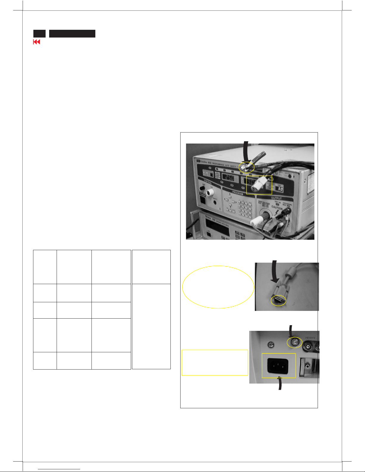
3.2. Connection
Hipot and Ground Continuity testing records have to be kept for
a period of 10 years.
* Turn on the power switch of monitor before Hipot and
Ground Continuity testing.
Connect the "video cable"
or "grounding screw"
to the CLIP on your tester.
Video cable
(Rear view of monitor)
Connect the power cord
to the monitor.
Grounding screw
Power outlet
(ChenHwa 9032 tester)
Clip
Clip
Safety test requirements
22
Go to cover page
V50 109B5
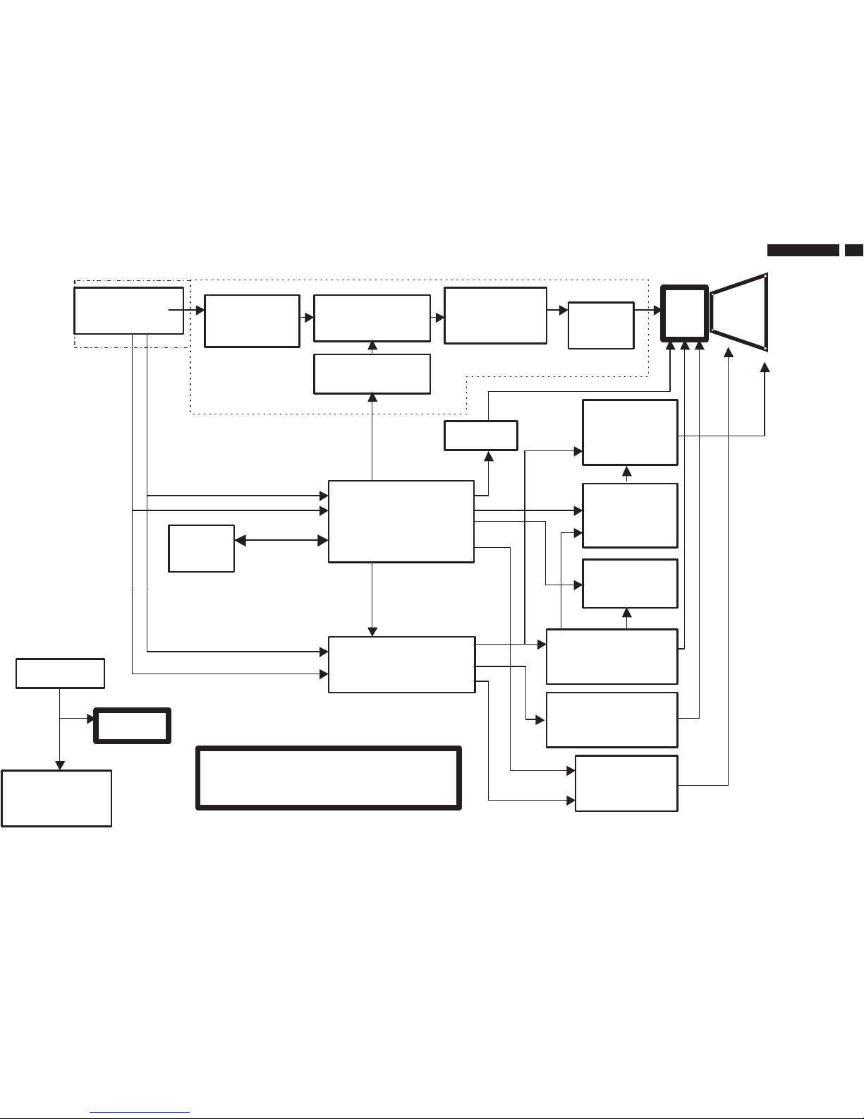
Block Diagram of V50 109B5
23
9
Go to cover page
V50 109B5
+ 190
+80
+13
-13
+8
+6.3
Pre-Amp
TDA4886
Post-Amp
LM2435T
OSD NOVA
68275-00031
Sync Processor
TDA4841
Power Supply
TEA1507
Degaussing
Rotation
EHT
X-RAY
UC3843AN
Linearity
Control
DAF / Cs
SWx4
IRF640
Horizontal
Deflection
Vertical
TDA8172
Muting & G1
Spot Killer
M24C1
6-BN6
HV
H-UNLOCK
MUTE
B+
HDRV
G1
SDA
SCL
Horizontal Frequency : 30~97kHz
Vertical Frequency : 50~160 Hz
SDA/SCL
(DDC 2B)
.
.
MCU
WT62P2
.
Flying-15 pin
D-SUB
DC
Restore
R
G
B
MHR
LF-III
TDA4823
SDA
SCL
CRT
24
V50 109B5
9
Go to cover page
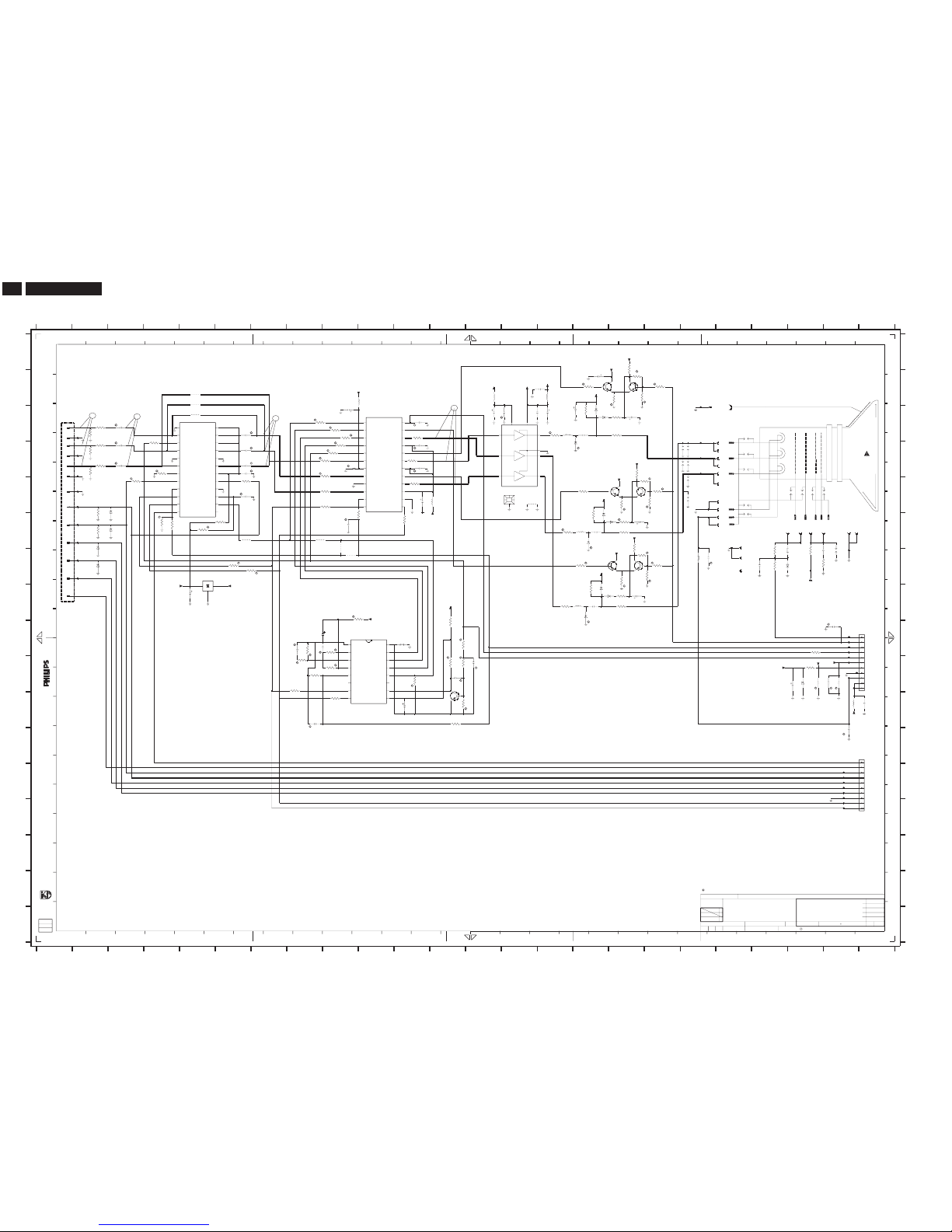
Video Panel Schematic diagram
C
*PWMCK/
G
S-TEST
Q
O
P
Q
A
B
C
D
E
F
G
H
I
V-SYNC
R
15
[R] STANDS FOR COMPONENTSRESERVED.
F308F2
F309F2
F310G2
F311D2
F312G2
F715C19
F716G22
F304D2
F306E2
F307E2
gedeeltelijk,is niet toegestaan danmet schriftelijke
E
G
H-SYNC
1/2WC.C
27
F729J23
F730K23
F732M23
F721I23
F722I23
F723I23
F724I23
F725J23
F726J23
F728J23
F701D19
SDA
B
E
M
Bc
1/2W
2814
26
1/2W
1/2W
2
J
K
L
12
G
+6V3
9302F8
9303F9
9304G9
9315B5
9316B5
9317C5
9716E14
F303C2
R
13
10
26
ABL
isprohibited without the writtenconsent of the copyright
7
5
17 18 19
B
A
F733M23
F734M23
F735M23
F736M23
F737M23
F738N23
F739N23
S002D19
S003E19
S004D19
s001G23
N
R
11 12 13 14 15 16 17 18 19 20 21 22 23 24
345
M
N
O
P
Q
1301-HC1
1703C19
1711-AG20
1711-BG20
1711-CF22
1711-DE19
25
G
17
2
R
Bi
1%
22
28
GND
D
1711-EF23
1711-FD19
1711-GE19
1711-HF19
1711-ID19
20 21 22
G
SDA
T
1
11
10
H-FLB
2KV
128
2309D9
2311D3
2312C11
2319D11
A
B
C
6 7 8 9 10 11 12 13 14 15 16
69
G1
GND
H1
18
CLBL
T
O
J
2723C16
2724C13
2725E19
1711-JF24
1712G22
1715-AF21
23 24
123456789
Ri
13
SB:57871 x1
K
F
B
B
2771G19
2772G21
2322I8
2323I9
2324I9
D
E
F
G
H
I
J
K
L
M
N
A
C
R
1
1/2W
M
DDC5V
109
DDC5V
VE-S/W
3306F2
3307J8
3308K9
3309C9
2726J22
2727C17
2728B15
1715-BD19
1715-CF22
1715-DD19
1715-EE19
1715-FF19
1715-GD19
1715-HF23
1715-IF20
2306K8
2307F9
2308D3
6
1%
B
2
25V
STANDS FOR CHIP COMPONENTS.
BRI
SDA(DDC)
B-IN
S
17
S-TEST
VIDEOBOARD
+12V
N
3327I9
2773I23
2774J23
2776L23
2336C6
2337D6
2338D6
2341E11
2342D11
2353D6
2354E6
2356H5
2702C14
2721C15
2722C15
POWERCON
1%
G1
4
Q
1/4W
3
Gi
toestemmingvan de auteursrechthebbende.
16
3726C16
3727C17
3310C9
3311D9
3312D2
2729C15
2730B16
2731F16
2732F17
2733D19
2751H16
2752H17
2753D19
2760J12
2761K11
2763J13
23
Allerechten voorbehouden. Verveelvuldiging, geheelof
+83
K
15
B
Rc
16
L
3754G17
3385F5
3703G21
3704G23
2778C9
2779J22
2781J23
2782K24
2783G22
2787C3
3301D2
3302D2
3303C2
3304D11
3305E2
25
GND
I
B
20
H
4001E14
5301B10
5303I11
5305G21
5307E12
5702B15
5705K23
5721C15
5751H16
5752F16
5771G19
5779B13
3728C17
3729C15
3731F17
3313D2
3314C2
3315C11
3316E9
3317F9
3318C8
3319D9
3323F4
3324F4
3325K12
3326J8
1/2WC.C
G2
Allrights reserved. Reproduction in wholeor in parts
H-SYNC
23
H
18 24
C
11
D
R
P
6772G2
7301C10
3755G18
3756G18
3757H17
3705J22
3706E11
3707F11
3716F17
3718D17
3719A17
3721B16
3722B17
3723B17
3724B17
3725B18
GND
21
22 24
R
S
GND
SCL(DDC)
7
BEAD
25V
H2
TOMAIN BD 8502
+8V
6301E3
6302F3
6303F2
3732F17
3733E16
3734F16
3735E17
3736E18
3737E18
3738E18
3739F15
3751G16
3752H16
3753G17
G-IN
20
G
I
F703D19
F704G23
F705F19
F706E19
F708F22
F709F23
27
V-SYNC
Gc
1000V
7302C5
7303G5
7304I10
3758H17
3759H15
3761I12
3762J11
3763J12
3764J12
3765K12
3767I12
3771G21
3772G22
3778I22
J
G
1/2WC.C
1
3362D4
3363E3
3367F6
3376D9
3378E9
3381D9
3383E6
O
L
P
TOMAIN BD 8501
3
4 8
F
owner.
6304J22
6721C16
6722C16
6723D16
6731F16
6732F17
6733F16
6751H16
6752H17
6753H16
6771G22
195
14 19
SCL
R-IN
FB:58361
+83
F702D19
[R]
3328I8
3329J8
3330J9
3332G6
3333G6
3334H10
3361D4
7701C14
7721B17
7722B17
7731E17
7732E17
7751G17
7752G17
7761K12
8713L24
8714I24
9301F6
2731
1u
160
[R]
[R]
[R]
[R]
[R]
21
SCL
GND
100
F736
+12A
100n
2729
10u
25
2319
***10 130
+8
3733
470R
TYT12-
--------
KONINKLIJKEPHILIPS ELECTRONICS N.V.2000
2003-04-08********
1
3XX000
1
V50SETNAMECHN
CLASS_NO
SUPERS.
1
NAME
DATEMGr CHECK
3138178 6517
109B50/00
VideoSchematics
A1
S004
Sparkgap1.0 mm
32003-06-20
MichaelWang/Ivy Su
1
10
11
2
3
4
5
6
7
8
9
9
41921
8714
13
1711-F
5
9304
75R
3302
25
2781
100n
100
2782
100n
5305
100n
2779
25
3705
100R
6302
BZX79-C12
68R
3381
BF422
7751
+12A
2725
F737
25
2354
100n
3725
68K
3726
330K
3732
10R
3301
75R
+3V3
F303
RGP10G
5702
1u8
1u
2732
6771
25
10u
2356
100
4
82R
3759
3327
5K6
9317
3383
100R
7731
BF422
2730
47u
25
S003
Sparkgap1.0 mm
3723
220K
3310
1K
2724
47u
25
25
2311
100n
F308
Sparkgap1.0 mm
S002
3727
10R
9716
160
1u
2751
R
4001
2733
1715-B
6
F728
6
7
8
9
3756
22K
8713
41920
1
10
2
3
4
5
F702
11
7752
BF422
4K7
3306
15K
3772
3308
100R
25
2341
47u
1/2WC.C
500
2728
1n
BF422
7732
1u8
5779
BAV21
6751
22K
3718
100n
2337
25
10R
3757
F722
3328
3K3
3739
82R
3312
68R
100n
2773
25
3315
47R
+83
+83
1715-G
11
F716
1u8
5705
25
2336
100n
1711-D
7
BC548C
7761
100MHZ
5303
2761
47u
3362
100R
F734
+5A
3326
3K3
5752
0u33
25
2787
100n
F701
2752
1u
100
3737
68K
3704
47R
BZX79-C12
6303
+5A
3767
4K7
+83
F721
+83A
F312
+8
50
2306
100p
F732
2721
100
3324
3K3
22u
3323
3K3
47R
3334
25
2771
100n
5
9301
3778
1K
1711-B
100n
2342
25
F311
3722
1K2
F709
R
15
3
RP
SCL
8
7
SDA
2
VCO
10
VFLB
7304
NT68275
AGND
1
AVCC4B
13
DGND
16
DVCC
9
12
FBKG
G
14
5
HFLB
INT
11
NC
6
F730
F715
1K2
3735
1
470p
2760
50
+83
1703
3707
100R
F725
F708
1715-H
12
2324
47u
3728
F735
4R7
3367
120R
+83
4R7
3385
6772
BZX79-C12
+83
3K3
3763
7722
BF422
25
2309
100n
1711-J
13
+12A
2778
47u
25
220K
3736
3325
8K2
100n
2312
25
SDA
12
Vin1
6
Vin2
8
Vin3
10
Vout1
22
Vout2
19
Vout3
16
Vp
7
Vp1
21
Vp2
18
Vp3
15
CLI
5
FBL
1
F_R1
23
F_R2
20
F_R3
17
GND
9
GNDX
14
HFB
11
LIM
24
OSD1
2
OSD2
3
OSD3
4
SCL
13
6
7301
TDA4886/V2
2727
1u
100
50
2323
10n
3333
100R
F310
3317
2K2
22K
3716
2322
50
100n
2308
25
3329
5K6
10n
F738
+12A
4K7
3755
68K
F739
3764
1M
3330
3765
6K8
3721
470R
100n
25
2338
100n
68R
3313
25
2776
5721
0u33
F304
BAV21
6721
1715-D
8
1
0u33
5751
Test
V
8
3
VBL
VDD
15
18
VDDa1
22
VDDa2
24
VDDref
5
VSSa120VSSa2
13
ACW
Bi
619
Bo
16
GND
GNDref
1
Gi4Go
21
H
17
9
HFL
INT
12
Ri2Ro
23
SCL
11
SDA
10
7
3703
7302
TDA4823PS_V1
14
ACI
1711-E
8
120R
3758
BZX79-C12
6301
+83
1715-I
13
F307
BAV21
6722
2
3305
4K7
3378
68R
9
F726
F706
22K
3719
1712
1
3314
68R
3753
1K2
1711-G
10
BF422
7721
12
F703
3363
100R
Sparkgap1.8 mm
s001
6753
BAV103
3319
1K
3734
330K
3311
1K
+8
+83
3706
47R
8
100R
3332
10
1301-H
9303
3752
330K
F704
50
2763
4n7
10n
2783
F309
1715-A
5
7
3304
47R
2753
1715-C
9316
1715-E
9
9315
7
BZX79-C5V6
6304
2726
10u
25
3771
1K5
BAV103
1K
3309
6723
+8
1711-I
12
2772
330p
500V
3361
100R
100n
2353
25
100R
3316
3751
470R
120R
3731
1711-C
6
BAV21
6752
BAV103
6733
10K
3762
1u8
5301
68R
3376
LE33CZ
7303
GND
IN
OUT
3738
22K
11
3729
82R
3754
220K
1711-H
+5A
3303
75R
F705
100R
3307
F729
+12A
1K
3318
3724
22K
1u8
5307
25
2774
100n
1711-A
1
9302
LM2435T
7701
5
GND
8
VBB4VCC
9
Vin1
7
Vin2
6
Vin3
1
Vout1
2
Vout2
3
Vout3
6732
BAV21
F723
3
6731
BAV21
100n
2702
25
F724
100n
100
2722
2723
1u
160
50
2307
47p
5771
100MHZ
F733
F306
10
3761
4R7
1715-F
56
57
58
59
 Loading...