

Philips V30 107T50, V30 107T00 Service Manual
Horizontal frequencies
30-71KHz
Service
Service
Service
TABLE OF CONTENTS
CAUTION: USE A SEPARATE ISOLATION TRANSFORMER FOR THIS UNIT WHEN SERVICING.
SAFETY NOTICE
ANY PERSON ATTEMPTING TO SERVICE THIS CHASSIS MUST FAMILIARIZE HIMSELF WITH THE CHASSIS
AND BE AWARE OF THE NECESSARY SAFETY PRECAUTIONS TO BE USED WHEN SERVICING ELECTRONIC
EQUIPMENT CONTAINING HIGH VOLTAGES.
Published by BCU Monitors Printed in Taiwan Copyright reserved Subject to modification Mar. 14 , 2003 GB
3138 106 10264
17" Auto Scan Colour Monitor
Chassis:V30
Description Page
Important Safety Notice-------------------------------- 2
Technical data ------------------------------------------- 3
Installation------------------------------------------------ 4
On-screen Display (OSD)--------------------------5 ~ 8
OSD Lock/Unlock, Burn In, Service mode-----9 ~ 12
Wiring Diagram ---------------------------------------- 14
Mechanical Instructions -------------------------- 15,16
Warning and Notes ---------------------------------- --17
Electrical Instructions---------------------------- 18~20
DDC Instructions ----------------------------------21~28
Block Diagram------------------------------------------ 29
Circuitry schematic diagrams(Main) ----------30~ 33
Description Page
Circuitry schematic diagrams(Audio) --------34~ 36
Circuitry schematic diagrams(Key ) ---------- 37, 38
Exploded View -----------------------------------------39
Recommend Parts List -------------------------------40
Spare Parts List------------------------------------41,42
Light Fram for Windows------------------------- 81~84
Repair Tips --------------------------------------------- 85
Safety Test Requirements----------------------------86
General Product Specification ----------------43~72
Repair Flow Chart-------------------------------- 73~80
General Troubleshooting Guide ------------- 87~109
REFER TO BACK COVER FOR IMPORTANT SAFETY GUIDELINES
MODEL : V30 107T50/00
S
Important Safety Notice
2
FOR PRODUCTS CONTAINING LASER :
Invisible laser radiation when open.
AVOID DIRECT EXPOSURE TO BEAM.
Use of controls or adjustments or
performance of procedures other than
those specified herein may result in
hazardous radiation exposure.
The use of optical instruments with this
product will increase eye hazard.
DANGER-
CAUTION-
CAUTION-
TO ENSURE THE CONTINUED RELIABILITY OF THIS
PRODUCT, USE ONLY ORIGINAL MANUFACTURER'S
REPLACEMENT PARTS, WHICH ARE LISTED WITH THEIR
PART NUMBERS IN THE PARTS LIST SECTION OF THIS
SERVICE MANUAL.
Proper service and repair is important to the safe, reliable
operation of all PHILIPS Consumer Electronics Company**
Equipment. The service procedures recommended by
PHILIPS and described in this service manual are effective
methods of performing service operations. Some of these
service operations require the use of tools specially designed
for the purpose. The special tools should be used when and
as recommended.
It is important to note that this manual contains various
CAUTIONS and NOTICES which should be carefully read in
order to minimize the risk of personal injury to service
personnel. The possibility exists that improper service
methods may damage the equipment. It is also important to
understand that these CAUTIONS and NOTICES ARE NOT
EXHAUSTIVE. PHILIPS could not possibly know, evaluate
and advise the service trade of all conceivable ways in which
service might be done or of the possible hazardous
consequences of each way. Consequently, PHILIPS has not
undertaken any such broad evaluation. Accordingly, a
servicer who uses a service procedure or tool which is not
recommended by PHILIPS must first satisfy himself
thoroughly that neither his safety nor the safe operation of the
equipment will be jeopardized by the service method selected.
* * Hereafter throughout this manual, PHILIPS Consumer
Electronics Company will be referred to as PHILIPS.
Critical components having special safety characteristics are
identified with a by the Ref. No. in the parts list and
enclosed within a broken line*
(where several critical components are grouped in one area)
along with the safety symbol on the schematics or
exploded views.
Use of substitute replacement parts which do not have the
same specified safety characteristics may create shock, fire,
or other hazards.
Under no circumstances should the original design be
modified or altered without written permission from Philips.
Philips assumes no liability, express or implied, arising out of
any unauthorized modification of design.
Servicer assumes all liability.
WARNING
* Bro ken Lin e
Go to cover page
107T5107T5

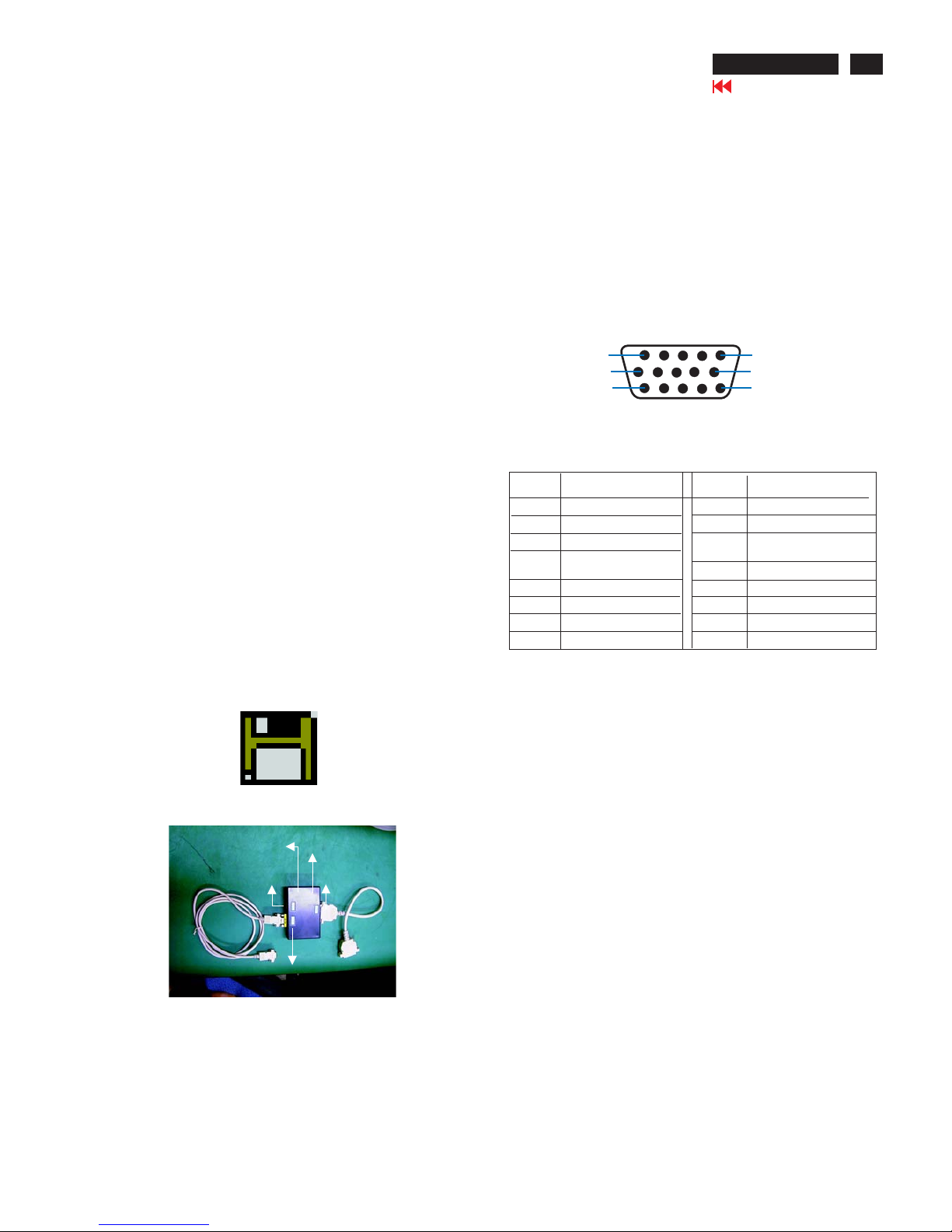
:The 15-pin D-sub connector(male) of the signal cable
Assignment
Assignment
Pin No.
Pin No.
Gnd
Gnd
Blue video input
2
7
6
4
5
3
1
9
12
11
14
13
15
10
Red video ground
Blue video ground
Green video ground
For self-test
+5V DDC
Gnd
Data clock line(SCL)
V.Sync(VCLK for DDC)
H.Sync /H
Bidirectional Data
Green video input
Red video input
3
Technical Data
9
Go to cover page
8
Pin assignment :
Automatic Power Saving
Data Storage
Factory preset modes:
This monitor has 8 factory-preset modes as indicated in the
Technical Specification*
ENERGY STAR is a U.S. registered mark. AS AN ENERGY STAR
PARTNER, DELL Computer Corporation HAS DETERMINED THAT
THIS PRODUCT MEETS THE ENERGY STAR GUIDELINES FOR
ENERGY EFFICIENCY.
R
This monitor is ENERGY STAR compliant.
this product meets the ENERGY STAR guidelines for energy
Efficiency
1
10
6
11
15
5
Dimensions : 17 inch
Pitch : 0.25
Deflection angle : 90 degrees
Glass : dark
Light transmission : 50%(CPT), 52.8%(LG), 52.6%(SDI),
Surface : AGARAS
Implosion protection : CRT is provided with P-mini-rim-band.
Black matrix : Yes
Phosphor : P22
EHT : 25 KV (Ib=0)
CRT source : CPT, LG, SDI
Horizontal scanning : 30 - 71 KHz
Vertical scanning : 50 - 160 Hz
Input signals
Video : Analog level
Sync. : Separate sync. with TTL level
Polarity : Positive or negative
Signal input level
Video : 0.7 Vp-p 75 ohms
Sync : TTL level
Impedance
Video : Terminated with 75 ohms
Sync : Terminated with 4.7K ohms pull down resistors
Video amplifiers
Dot Rate : 108 Mhz
Operating limits
Temperature : 0C to 40C
Humidity : 10 to 90% (W/O condensation)
Air pressure : 700 ~ 1100 mbar
Non-operating limits (storage)
Temperature : -25C to 65C
Humidity : 5 to 95 % (W/O condensation)
Altitude : 300 to 1100 mbar
Carton box
A-1 Size (with pedestal)
496(W)416(H)556(D)
A-2 Carton paper : double wall AB flute corrugate
board, color brown
Bursting : 19.3 kgf/cm min
Compression : 600 kgf min
White color adjustment
Based on the 1931 CIE chromatic diagram (x,y) coordinates
of white display on screen center should be:
For 9300 K X = 0.283 0.015 Y = 0.297 0.015
For 6500 K X = 0.313 0.015 Y = 0.329 0.015
For sRGB X = 0.313 0.015 Y = 0.329 0.015
Scanning
2
Factory preset modes : 8
Resolution H. freq. V. freq. H. V.
1. 720 x 400 31.5 KHz 70Hz (VGA) - +
2. 640 x 480 31.47 KHz 60Hz (VGA) - -
3. 640 x 480 43.3 KHz 85Hz (VESA) - -
4. 800 x 600 46.9 KHz 75Hz (VESA) + +
5. 800 x 600 53.674KHz 85Hz (VESA) + +
6. 1024 x 768 60.0 KHz 75Hz (VESA) + +
7. 1024 x 768 68.7 KHz 85Hz (VESA) + +
8. 1280 x 1024 64.0 KHz 60Hz (VESA) + +
Signal
H-Sync V-Sync Video
Compliance
Requirement
Power
On Active Active Active Mandatory 75w
Off Inactive Active Blanked Mandatory 2w
Off Active Inactive Blanked Mandatory 2w
Off Inactive Inactive Blanked Mandatory 2w
R
R
107T5
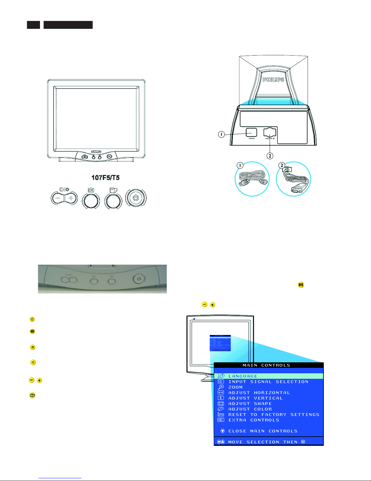
Front control & OSD
4
9
Go to cover page
Power button switches your monitor on.
OK button which when pressed will take you to the OSD
controls
Contrast hotkey. When the "-" button is pressed,
the adjustment controls for the CONTRAST will show up.
Brightness hotkey. When the "+" button is pressed,
the adjustment controls for BRIGHTNESS will show up.
"-" and "+" buttons, are used for adjusting the OSD of your
Monitor.
Description of the On Screen Display
What is the On-Screen Display?
Basic and simple instruction on the control keys.
This is a feature in all Philips monitors which allows an end-user to
adjust screen performance of monitors directly though an on-screen
instruction window. The user interface provides user-friendliness and
ease-of-use when operating the monitor.
On the front controls of your monitor, once you press the button, the
On Screen Display (OSD) Main Controls window will pop up and you
can now start making adjustments to your monitor's various features.
Use the the keys to make your adjustments within.
Rear view
1. Power in - attach power cable here.
2. Video In - this is a cable which is already attached to your monitor.
Connect the other end of the cable to your PC.
Front View
LightFrame hotkey. When the button is pressed, the adjustment
controls for LightFrame will show up.
Front control
107T5
5
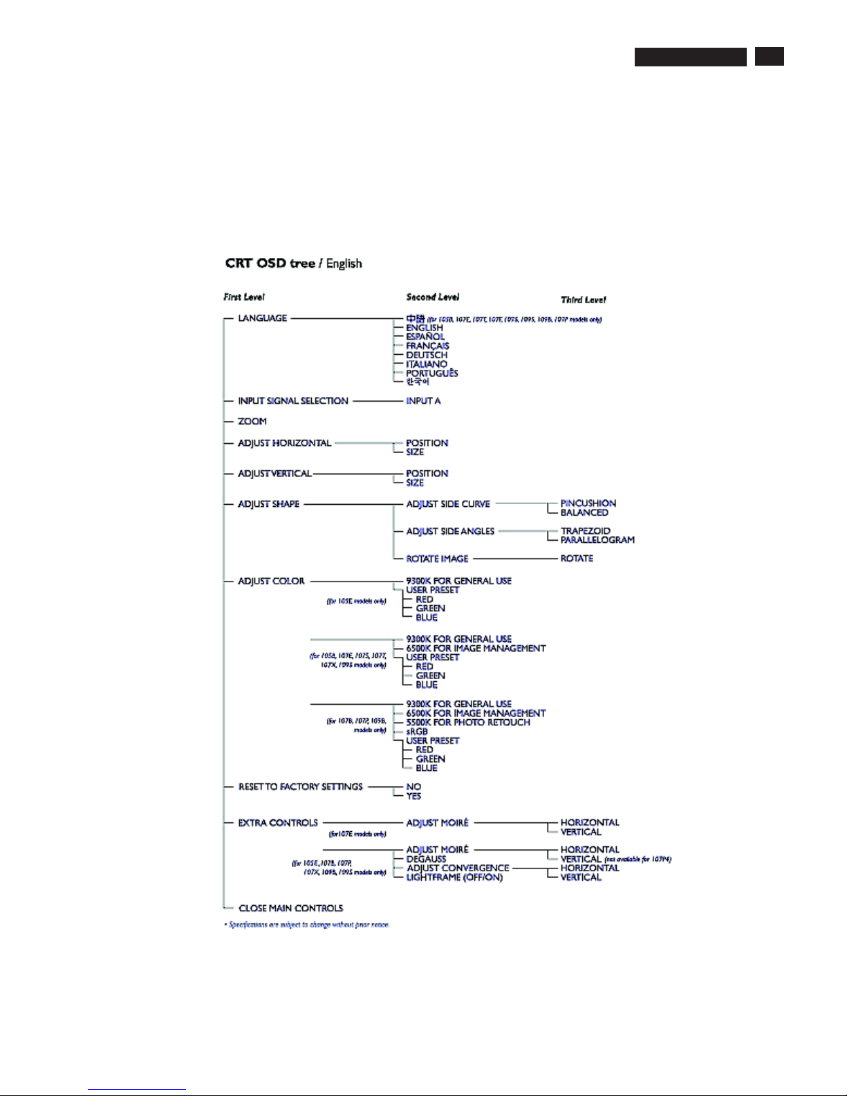
OSD menu tree
The OSD Tree
Below is an overall view of the structure of the On-Screen
Display. You can use this as reference when you want to
later on work your way around the different adjustments.
9
Go to cover page
107T5
6
OSD Adjustments
9
Go to cover page
The OSD Controls
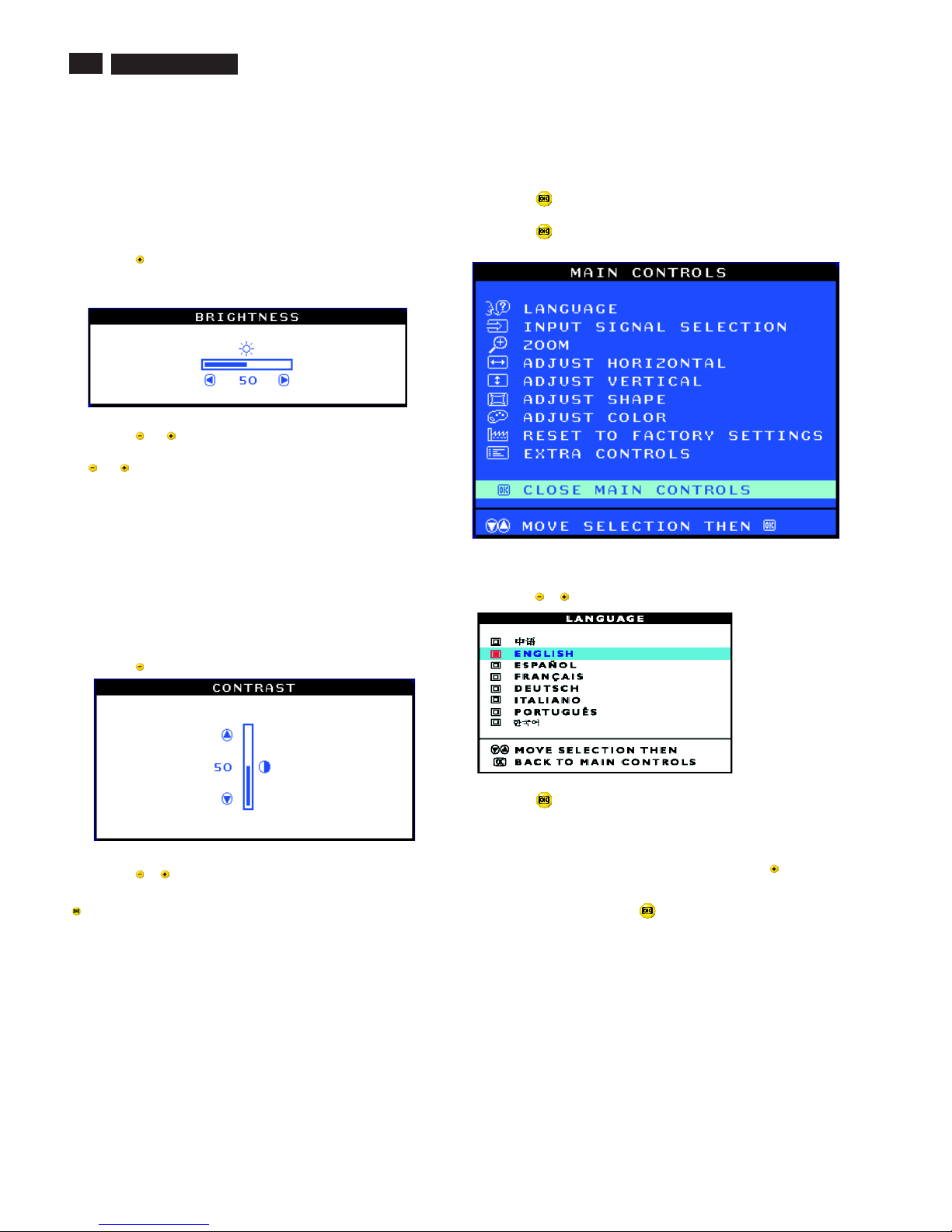
BRIGHTNESS
To adjust your screen's brightness, follow the steps below. Brightness is
the overall intensity of the light coming from the screen. A 50%
brightness is recommended.
1) Press the button on the monitor. The BRIGHTNESS window
appears.
2) Press the or button to adjust the brightness.
3) When the brightness is adjusted to the level desired, stop pressing
the or button and after three seconds the BRIGHTNESS window
will disappear with the new adjustment saved.
After the BRIGHTNESS window has disappeared, to
continue to the CONTRAST window, follow the steps under CONTRAST.
CONTRAST
To adjust your screen's contrast, follow the steps bellow. Contrast is the
difference between the light and dark areas on the screen. A 100%
contrast is recommended.
1) Press the button on the monitor. The CONTRAST window appears.
2) Press the or button to adjust the contrast.
3) When the contrast is adjusted to the level desired, stop pressing the
Button and after three seconds the CONTRAST window will
disappear with the new adjustment saved.
After the CONTRAST window has disappeared, to
continue to the MAIN CONTROLS, follow the steps under LANGUAGE
Smart Help
Smart Help
LANGUAGE
The ON SCREEN DISPLAY shows its settings in one of eight languages.
The default is English, but you can select French, Spanish, German,
Italian, Simplify-Chinese, Korea, Brazilian or Portuguese.
1) Press the button on the monitor. The MAIN CONTROLS window
appears. LANGUAGE should be highlighted.
2) Press the button again. The LANGUAGE window appears.
3) Press the or button until the desired language is highlighted.
4) Press the button to confirm your selection and return to MAIN
CONTROLS window. CLOSE MAIN CONTROLS will be highlighted...
After returning to MAIN CONTROLS...
...tocontinue to INPUT SIGNAL SELECTION, press the button until
INPUT SIGNAL SELECTION is highlighted. Next, follow steps3-5
under INPUT SIGNAL SELECTION.
...toexit completely, press the button
Smart Help
107T5
7
OSD Adjustments (Continued)
9
Go to cover page
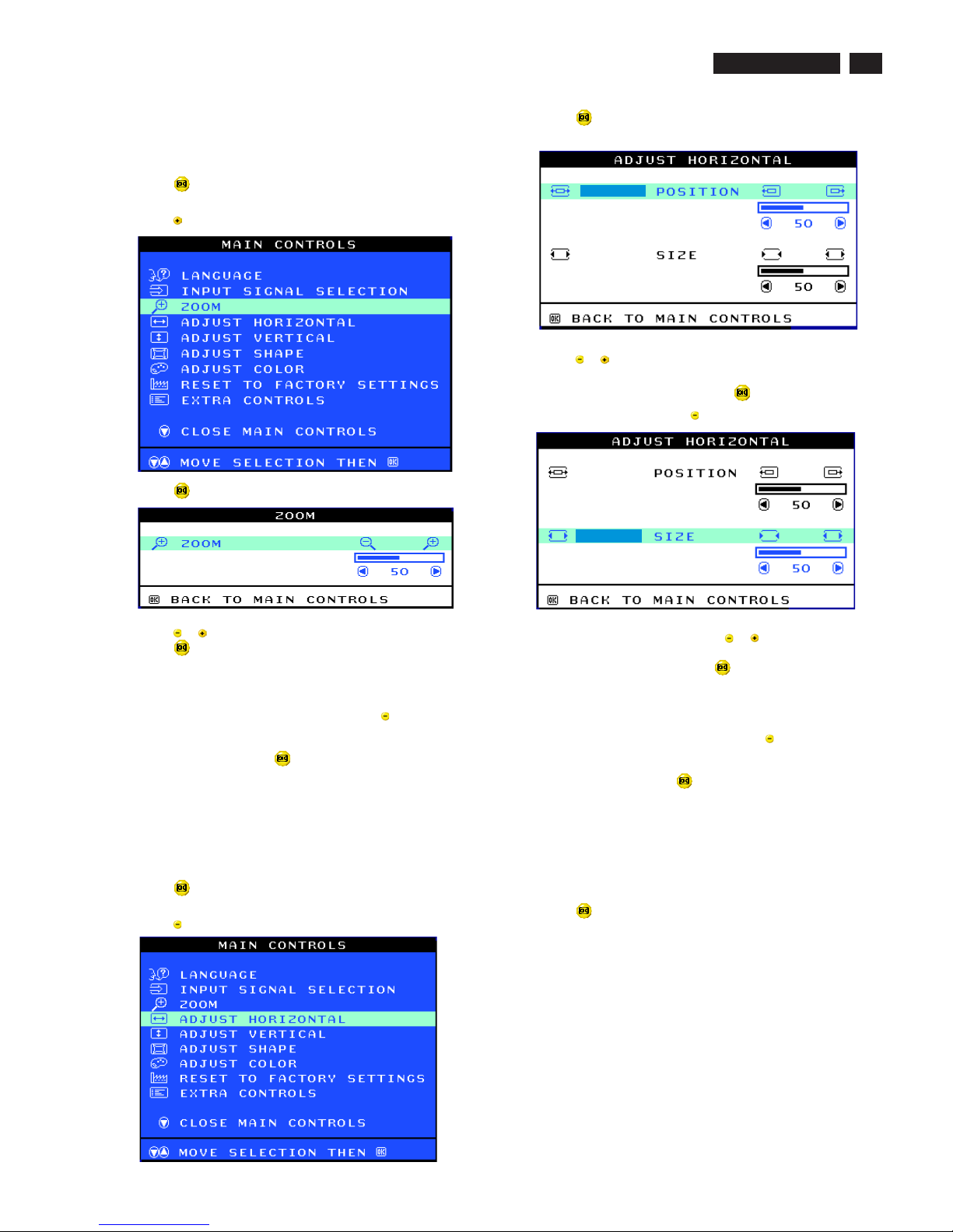
ZOOM
ADJUST HORIZONTAL
ZOOM increases or decreases the size of the images on your screen.
To adjust the ZOOM follow the steps below.
1) Press the button on the monitor. The MAIN CONTROLS window
appears.
2) Press the button until ZOOM is highlighted.
3) Press the button. The ZOOM window appears.
4) Press the or button to adjust ZOOM.
5) Press the button to confirm your selection and return to the MAIN
CONTROLS window. CLOSE MAIN CONTROLS will be highlighted.
After returning to MAIN CONTROLS...
...tocontinue to ADJUST HORIZONTAL, press the button until
ADJUST HORIZONTAL is highlighted. Next, follow steps3-7under
ADJUST HORIZONTAL.
...toexit completely, press the button
ADJUST POSITION under ADJUST HORIZONTAL shifts the image on
your screen either to the left or right. Use this feature if your image does
not appear centered. ADJUST SIZE under ADJUST HORIZONTAL
expands or controls the image on your screen, pushing it out toward the
left and right sides or pulling it in toward the center.
1) Press the button on the monitor. The MAIN CONTROLS window
appears.
2) Press the button until ADJUST HORIZONTAL is highlighted.
Smart Help
3) Press the button. The ADJUST HORIZONTAL window appears.
ADJUST POSITION should be highlighted.
4) Press the or button to move the image to the left or right.
5) When the position is adjusted, press the button to return to MAIN
CONTROLS window, or press the to highlight ADJUST SIZE.
6) To adjust the horizontal size, press the or button.
7) When the size is adjusted, press the button to return to MAIN
CONTROLS window. CLOSE MAIN CONTROLS will be highlighted.
After returning to MAIN CONTROLS...
...tocontinue to ADJUST VERTICAL, press the button until ADJUST
VERTICAL is highlighted. Next, start with step 3 under ADJUST
VERTICAL and follow the directions.
...toexit completely, press the button
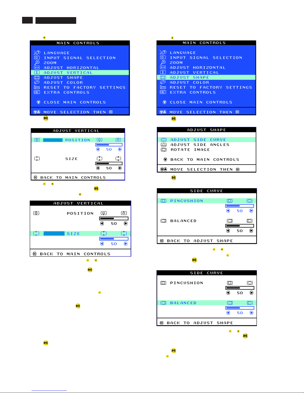
ADJUST POSITION under ADJUST VERTICAL shifts the image on
your screen either up or down. Use this feature if your image does not
appear centered. ADJUST SIZE under ADJUST VERTICAL expands or
controls the image on your screen, pushing it out toward the top or
bottom or pulling it in toward the center.
1) Press the button on the monitor. The MAIN CONTROLS window
appears.
ADJUST VERTICAL
Smart Help
107T5
8
9
Go to cover page
OSD Adjustments (Continued)
2) Press the button until ADJUST VERTICAL is highlighted.
3) Press the button. The ADJUST VERTICAL window appears.
ADJUST POSITION should be highlighted.
4) Press the or button to move the image up or down.
5) When the position is adjusted, press the button to return to MAIN
CONTROLS window, or press the button to highlight ADJUST SIZE.
6) To adjust the vertical size, press the or button.
7) When the size is adjusted, press the button to return to MAIN
CONTROLS window. CLOSE MAIN CONTROLS will be highlighted.
After returning to MAIN CONTROLS...
...tocontinue to ADJUST SHAPE, press the button until ADJUST
SHAPE is highlighted. Next, start with step 3 under ADJUST SHAPE
and follow the directions.
...toexit completely, press the button
ADJUST SHAPE
ADJUST SIDE CURVE
ADJUST SIDE CURVE under ADJUST SHAPE allows you to adjust two
of the five preset options. These two options are PINCUSHION and
BALANCED pincushion. Note: use these features only when the picture
is not square.
1) Press the button on the monitor. The MAIN CONTROLS window
appears.
Smart Help
2) Press the button until ADJUST SHAPE is highlighted.
3) Press the button. The ADJUST SHAPE window appears.
ADJUST SIDE CURVE should be highlighted.
4) Press the button. The SIDE CURVE window appears.
PINCUSHION should be highlighted.
5) To adjust the pincushion, press the or button.
6) When the pincushion is adjusted, press the button to highlight
BALANCED or press the button to return to the ADJUST SHAPE
window.
7) To adjust the balanced pincushion, press the or button.
8) When the balanced pincushion is adjusted, press the button to
return to the ADJUST SHAPE window. BACK TO MAIN WINDOWS will
be highlighted.
9) Press the button to return to the MAIN CONTROLS window, or
press the button until ADJUST SIDE ANGLES is highlighted.
107T5
9
Smart Help After returning to MAIN CONTROLS...
...to continue to ADJUST SIDE ANGLES, start with step 5 under
ADJUST SIDE ANGLES and follow the directions.
...to exit completely, press the button twice.
...to adjust only the BALANCED pincushion, follow steps1-4above,
then press the button, and follow steps7-9.
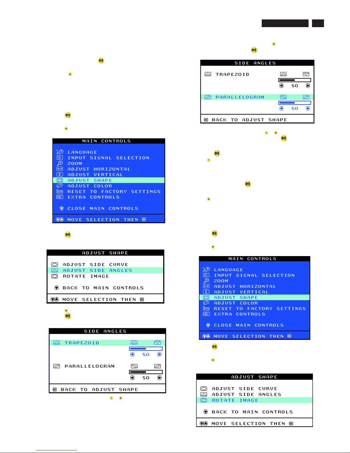
ADJUST SIDE ANGLES under ADJUST SHAPE allows you to adjust
two of the five preset options. These two options are TRAPEZOID and
PARALLELOGRAM. Note: use these features only when the picture is
not square.
1) Press the button on the monitor. The MAIN CONTROLS window
appears.
2) Press the button until ADJUST SHAPE is highlighted.
3) Press the button. The ADJUST SHAPE window appears.
ADJUST SIDE CURVE should be highlighted.
4) Press the button to highlight ADJUST SIDE ANGLES.
5) Press the button. The SIDE ANGLES window appears.
TRAPEZOID should be highlighted.
6) To adjust the trapezoid, press the or button.
ADJUST SIDE ANGLES
7) When the trapezoid is adjusted, press the button to highlight
PARALLELOGRAM or press the button to return to the ADJUST
SHAPE window.
8) To adjust the parallelogram, press the or button.
9) When the parallelogram is adjusted, press the button to return to
the ADJUST SHAPE window. BACK TO MAIN WINDOWS will be
highlighted.
10) Press the button to return to the MAIN CONTROLS window, or
press the button until ROTATE IMAGE is highlighted.
After returning to MAIN CONTROLS...
...to continue to ROTATE IMAGE, start with step 5 under ROTATE
IMAGE and follow the directions.
...to exit completely, press the button twice.
...to adjust only the PARALLELOGRAM, follow steps1-4above, then
press the button, and follow steps 7 -9
ROTATE IMAGE under ADJUST SHAPE allows you to adjust one of
the five preset options. These two options are PINCUSHION and
BALANCED pincushion. Note: use this feature only when the picture is
not square.
1) Press the button on the monitor. The MAIN CONTROLS window
appears.
2) Press the button until ADJUST SHAPE is highlighted.
3) Press the button. The ADJUST SHAPE window appears.
ADJUST SIDE CURVE should be highlighted.
4) Press the arrow until ROTATE IMAGE is highlighted.
ROTATE IMAGE
Smart Help
9
Go to cover page
OSD Adjustments (Continued)
107T5
10
9
Go to cover page
OSD Adjustments (Continued)
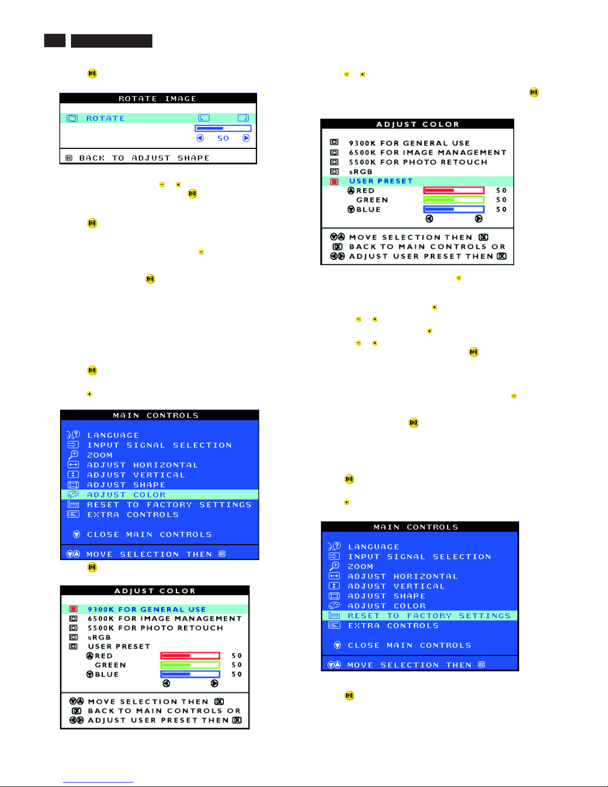
5) Press the button. The ROTATE IMAGE window appears. ROTATE
should be highlighted.
6) To adjust the rotation, press the or button.
7) When the rotation is adjusted, press the button to return to the
ADJUST SHAPE window. BACK TO MAIN CONTROLS should be
highlighted.
8) Press the button to return to MAIN CONTROLS.
After returning to MAIN CONTROLS...
...tocontinue to ADJUST COLOR, press the button until ADJUST
COLOR is highlighted. Next, start with step 3 under ADJUST COLOR
and follow the directions.
...to exit completely, press the button twice.
ADJUST COLOR
Your monitor has two preset options you can choose from. The first
option is for GENERAL USE, which is fine for most applications. The
second option is for GAMES, which is for playing computer games.
When you select one of these options, the monitor automatically adjusts
itself to that option. There is also a third option, USER PRESET, which
allows you to adjust the colors on your screen to a setting you desire.
1) Press the button on the monitor. The MAIN CONTROLS window
appears.
2) Press the button until ADJUST COLOR is highlighted.
3) Press the button. The ADJUST COLOR window appears.
Smart Help
4) Press the or button to highlight 9300K for GENERAL USE,
6500K for GAMES, or USER PRESET.
5) Once you have highlighted GENERAL USE or GAMES, press the
button to confirm you selection and return to the MAIN CONTROLS
window. CLOSE MAIN CONTROLS will be highlighted.
6a) If USER PRESET is highlighted, press the button to highlight RED.
Next, press the LEFT CURSOR or RIGHT CURSOR button to adjust the
color red.
6b) When finished with RED, press the button to highlight GREEN.
Next, press the or button to adjust the color green.
6c) When finished GREEN, press the button to highlight BLUE.
Next, press the or button to adjust the color blue.
6d) When all adjustments are complete, press the button to confirm
your adjustments and return to the MAIN CONTROLS window. CLOSE
MAIN CONTROLS will be highlighted.
After returning to MAIN CONTROLS. . .
...tocontinue to RESET TO FACTORY SETTINGS, press the button
until RESET TO FACTORY SETTINGS is highlighted. Next, start with
step 3 under RESET TO FACTORY SETTINGS.
...toexit completely, press the button.
RESET TO FACTORY SETTINGS returns everything in all the windows
to factory presets.
1) Press the button on the monitor. The MAIN CONTROLS window
appears.
2) Press the button until RESET TO FACTORY SETTINGS is
highlighted.
3) Press the button. The RESET TO FACTORY SETTINGS window
appears.
RESET TO FACTORY SETTINGS
Smart Help
107T5
11
OSD Adjustments (Continued)
9
Go to cover page
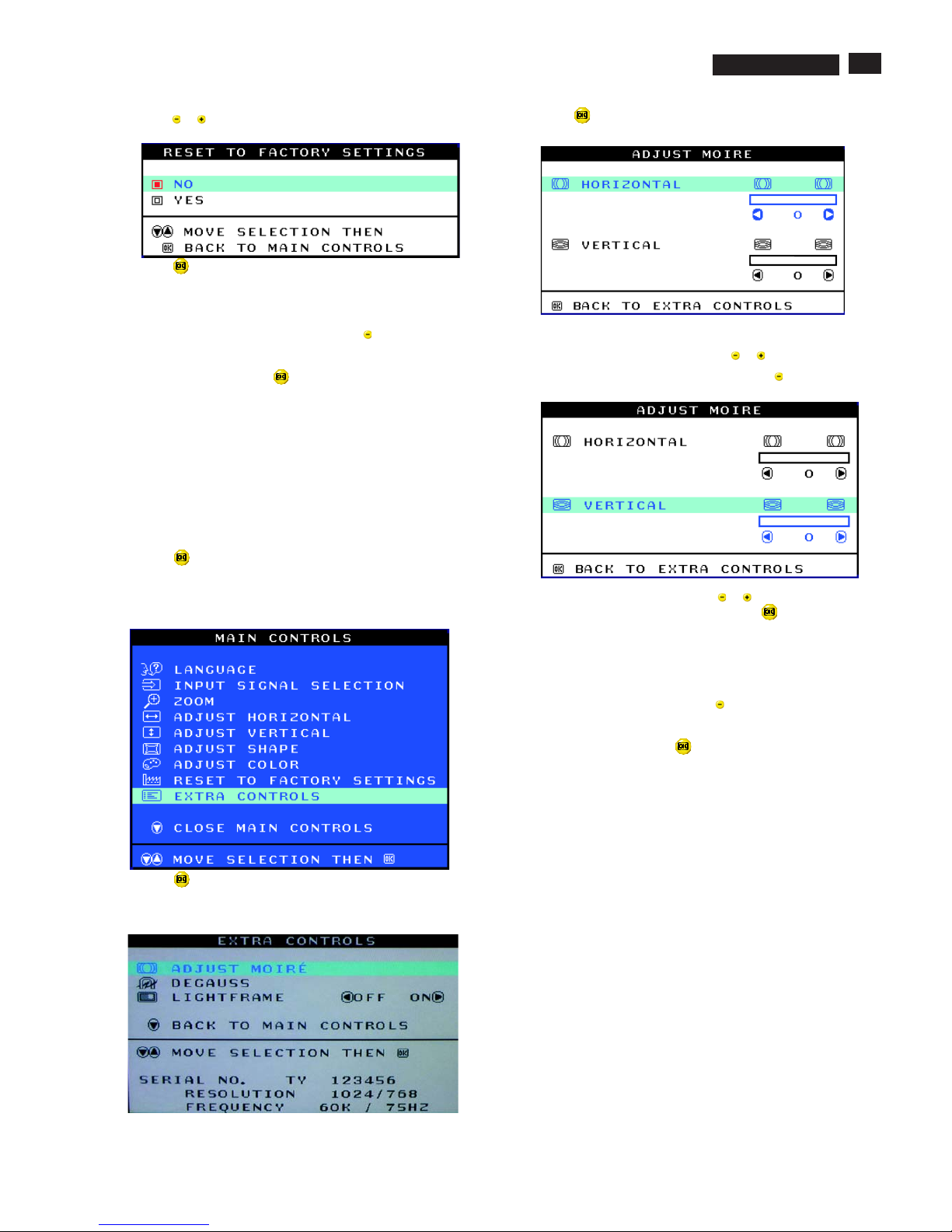
ADJUST MOIRE
EXTRA CONTROLS is a set of three features, including ADJUST
MOIRE. Moire is a fringe pattern arising from the interference between
two superimposed line patterns. To adjust your moire, follow the steps
below. Note: Use only if necessary. By activating ADJUST MOIRE,
sharpness can be affected.
1) Press the button on the monitor. The MAIN CONTROLS window
appears.
2) Press the DOWN CURSOR button until EXTRA CONTROLS is
highlighted.
3) Press the button. The EXTRA CONTROLS window appears. will
be highlighted.ADJUST MOIRE will
4) Press the button. The ADJUST MOIRE window appears.
HORIZONTAL will be highlighted.
5) To adjust the horizontal moire, press the or button.
4) Press the or button to select YES or NO. NO is the default. YES
returns all settings to their original factory adjustments.
5) Press the button to confirm your selection and return to the MAIN
CONTROLS window. CLOSE MAIN CONTROLS will be highlighted.
After returning to MAIN CONTROLS...
...tocontinue to EXTRA CONTROLS, press the button until EXTRA
CONTROLS is highlighted. Next, start with step 3 under EXTRA
CONTROLS.
...toexit completely, press the button.
EXTRA CONTROLS
Smart Help
6) When the horizontal moire is adjusted, press the button to highlight
VERTICAL.
7) To adjust the vertical moire, press the or button.
8) When the vertical moire is adjusted, press the button to return to
the EXTRA CONTROLS window. BACK TO MAIN CONTROLS will be
highlighted.
Smart Help After returning to MAIN CONTROLS...
...tocontinue to DEGAUSS, press the button until is
highlighted. Next, start with step 3 under EXTRA CONTROLS,
DEGAUSS.
...toexit completely, press the button.
DEGAUSS
107T5
12
OSD Adjustments (Continued), Troubleshooting
9
Go to cover page
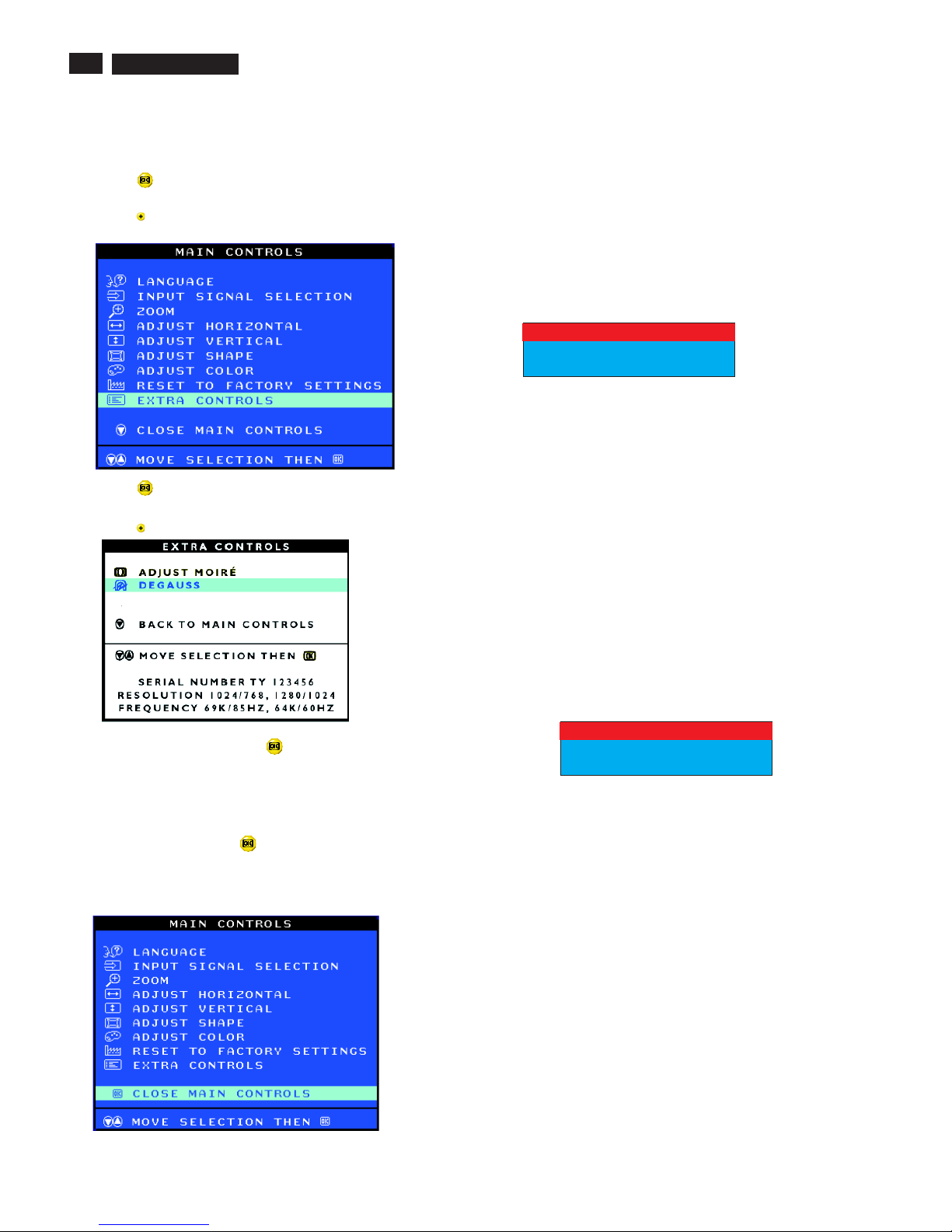
Smart Help After returning to MAIN CONTROLS...
...toexit completely, press the button.
CLOSE MAIN CONTROLS
Monitor Specific Troubleshooting
Self-Test Feature Check (STFC)
NO SIGNAL INPUT
Your monitor provides a self-test feature that allows you to check
whether your monitor is functioning properly. If your monitor and
computer are properly connected but the monitor screen remains
dark, run the monitor self-test by performing the following steps:
1. Turn off both your computer and the monitor.
2. Unplug the video cable from the back of the computer.
3. Turn on the monitor.
If the monitor is functioning properly, you will see a OSD
message as shown in the following illustration:
This box also appears during normal system operation if the
video cable becomes disconnected or damaged. This box
will remain on for one minute, go off five seconds, then on for
one minute, and will repeat cycle.
1. Turn off your monitor and reconnect the video cable;
then turn on both your computer and the monitor.
2. While in self-test mode, the LED remains green and the
pattern remains on and stationary.
If your monitor screen still remains dark after you use the
previous procedure, check your video controller and computer
system; your monitor is functioning properly.
If there is something wrong with the input signal, a message
appears on the screen although the power indicator LED is
still on. The message may indicate that the monitor is NO
SIGNAL INPUT or that you need to check the signal cable.
NO SIGNAL INPUT
ATTENTION
CHECK SIGNAL CABLE
ATTENTION
DEGAUSS
EXTRA CONTROLS is a set of three features, including DEGAUSS.
Degaussing removes electromagnetic build up that may distort the color
on your screen.
1) Press the button on the monitor. The MAIN CONTROLS window
appears.
2) Press the button until EXTRA CONTROLS is highlighted.
3) Press the button. The EXTRA CONTROLS window appears.
ADJUST MOIRE will be highlighted.
5) To degauss your screen, press the button. Your screen will be
degaussed, then the MAIN CONTROLS window will reappear. CLOSE
MAIN CONTROLS will be highlighted.
4) Press the button until DEGAUSS is highlighted.
107T5
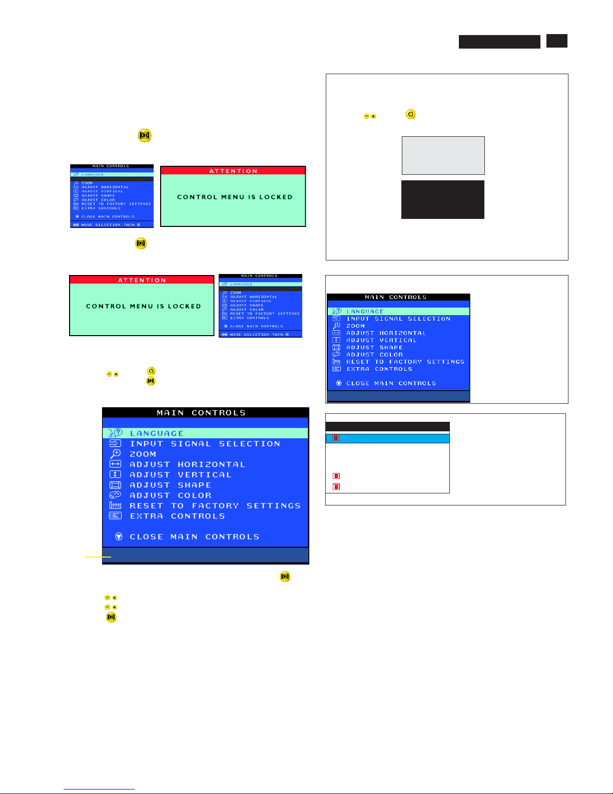
To access factory mode
1. Turn off monitor (don't turn off PC)
2. Press '" " and " " simultaneously on the front control
panel,then press " ",wait till the OSD menu with characters
V30 107T5 V0.48 20021218 (below OSD menu)" come on the
screen of monitor.
3. If OSD menu disappears on the screen of monitor, press " "
again (anytime), then the OSD menu comes on the screen again.
4. Using " " : to select OSD menu.
5. Using " " : to increase or decrease the setting.
6. Using " " to access/confirm the selection.
7. After alignment of factory mode, turn off monitor (if you do not turn
off monitor, the OSD menu is always at the factory mode), then
turn on monitor again (at this moment, the OSD menu goes back
to user mode).
To leave factory mode
13
Lock/Unlock, Factory Mode, Burn In, Service Mode
9
Go to cover page
OSD Lock
Switch on OSD lock feature:
Switch off OSD lock feature:
OSD lock is a feature which disables the OSD controls. It can be used
when the monitor is set up for demonstration purposes or when
adjustment of the OSD is not desirable.
Press and hold the button continuously for 15 seconds.
Release the button when the message
"CONTROL MENU IS LOCKED" appears.
Press and hold the button continuously for 15 seconds or until the
message window "CONTROL MENU IS LOCKED" disappears, and
"MAIN CONTROLS" appears.
To access BURN IN mode
Reconnect the video cable, then return to normal image.
First of all, monitor displays an image.
1. Disconnect the video cable (interface cable).
2. Turn off monitor
3. Press '" " and " " simultaneously on the front control
panel,then the BURN IN mode comes on the screen of monitor
as below.
50 seconds around
5 seconds around
repeatly
4.
SERVICE MODE (Indication-Factory mode)
MODEL SELECT
02060
V30 107T5 V0.48 20021218
------------------------>
02060: stands for
1. using 10 hours already.
2. turn on/off 10 times.
3. using several hours
+ turn on/off monitor.
Default setting of MODEL SELECT (Do not change it.)
MODEL SELECT
107T5
107B5
RESERVE
RESERVE
RESERVE
SWDDC
MODEL SELECT
V30 107T5 V0.48 20021218
Factory
Mode
Indicator
LF 3
107T5
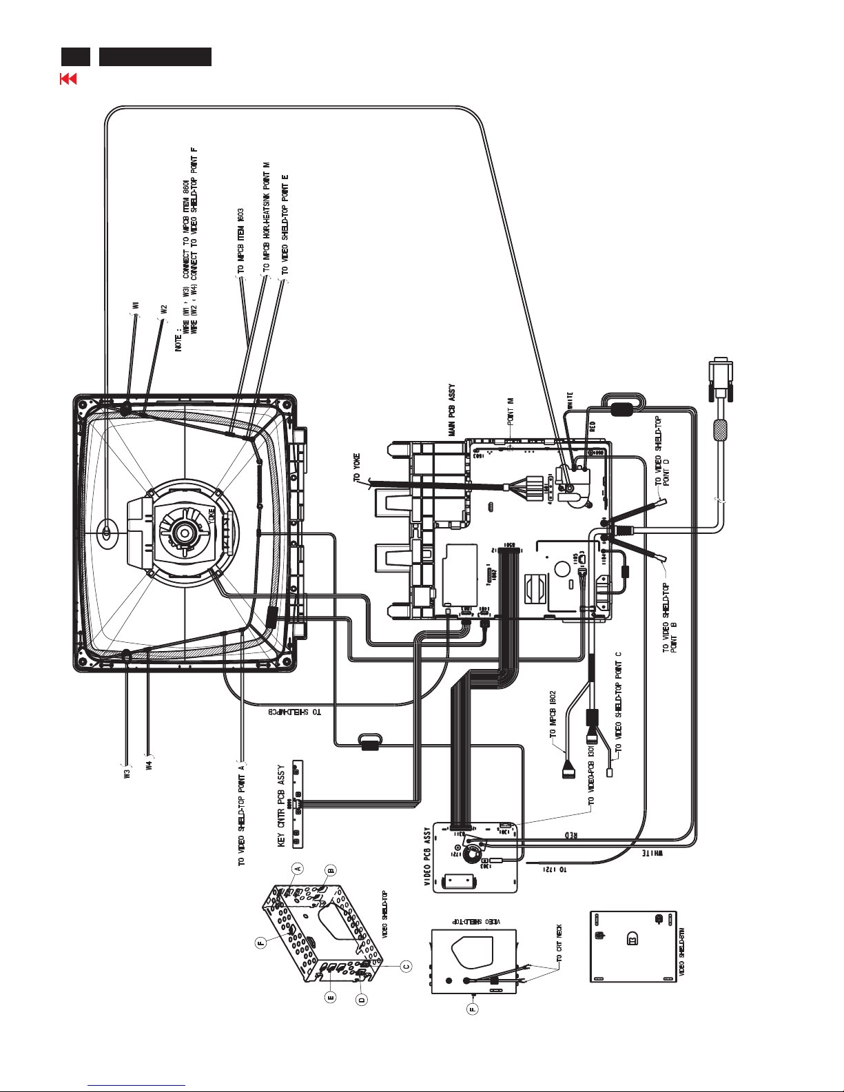
Wiring Diagram
14
Go to cover page
107T5
9
Go to cover page
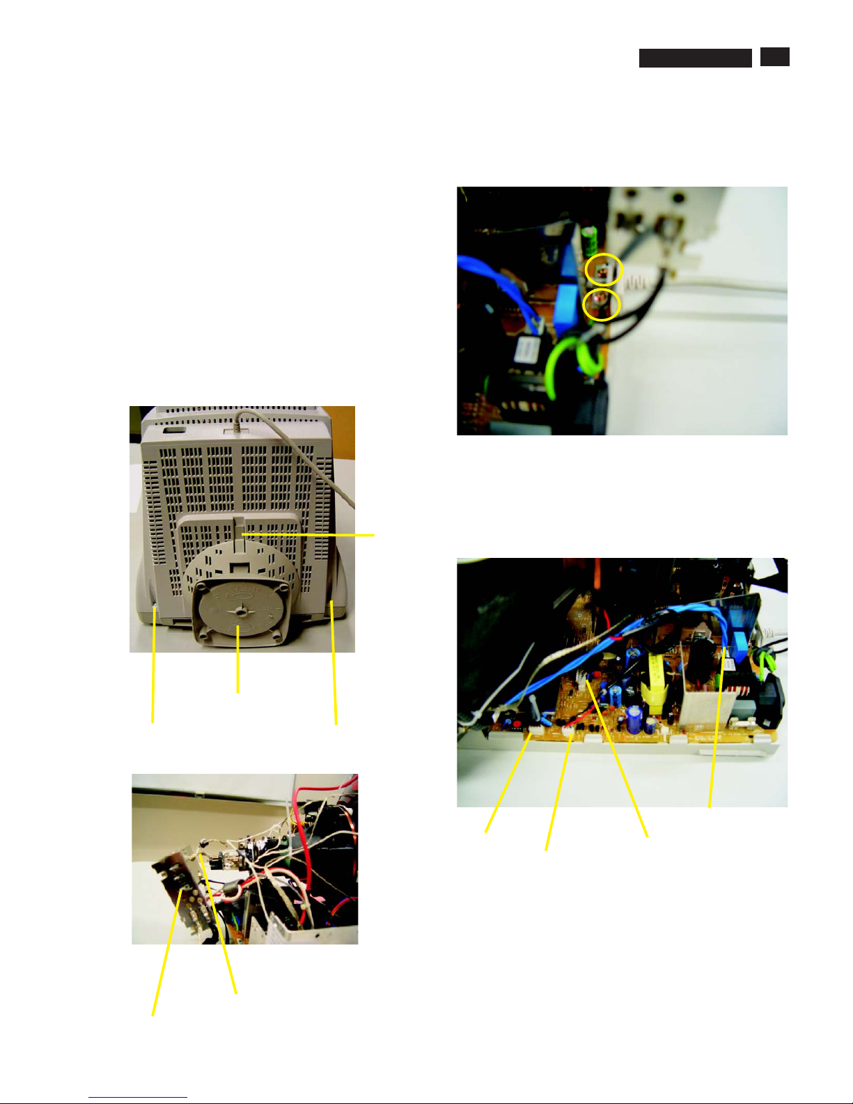
15
Mechanical Instructions
0. General
2. Video panel
3.Main board connector in Fig. 4
To be able to perform measurements and repairs on the "circuit
boards", these unit should placed in the service position first.
-Remove 2 screws as shown
-Remove back cover as shown
-Remove pedestal as shown
-Disconnect york wire
-Disconnect rotation connector
-Disconnect control board connector
-Remove Screw for fixed I/F cable
-Remove signal connector
-Remove degaussing wire connector
1.Remove the rear cover in Fig. 1.
- Disconnect the wire between metal shield of Video panel and
CRT neck as shown in Fig. 2.
- Disconnect the CRT ground from Video panel.
- Remove screw grounding and grounding wire in Fig. 3.
Fig. 1
Screw
Screw
Pedestal ass'y
Video Panel
CRT grouding wirel
Fig. 2
Clip
Fig. 3
Fig. 4
screw - grounding
Control connector
Signal connector
Degaussing wire connector
Rotation connector
===============>
107T5

Go to cover page
16
Mechanical Instructions
4. Main panel with Bottom Tray
-Remove 2 screws for disconnect the Bottom tray as Fig. 5.
-Pull the bottom tray from fig. 6
to fig. 7.
on press right and left side clip
Reconnect connectors, some wires and panels (chassis),
service position can be available for DC/AC measurement
as shown in Fig. 8.
5. SERVICE POSITION
Fig. 6
Fig. 7
Fig. 5
Press CLIP
Screw
Pull-up
=======>
Main panel
Video panel
Fig. 8 SERVICE POSITION
107T5
17
Go to cover page
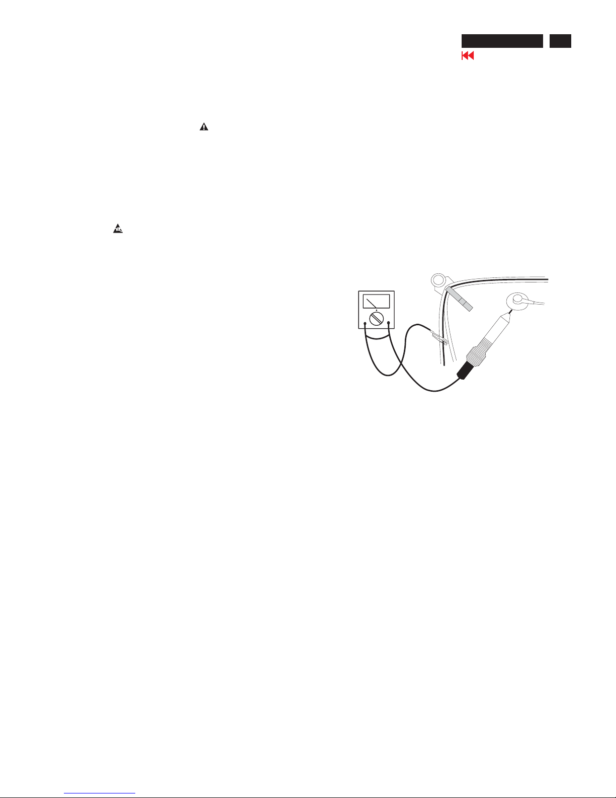
Warning and Notes
Fig.1
V
Warnings
1
2
0V
3 ESD
4
5
6
7
8
9
10.
11.
. Safety regulations require that the unit should be returned
in its original condition and that components identical to
the original components are used. The safety components
are indicated by the symbol .
. In order to prevent damage to ICs and transistors, all
high-voltage flash-overs must be avoided. In order to
prevent damage to the picture tube, the method shown
in Fig. 1 should be used to discharge the picture tube.
Use a high-voltage probe and a multimeter (position DC-V).
Discharge until the meter reading is (after approximately
30 seconds).
.
All ICs and many other semiconductors are sensitive to
electrostatic discharges (ESD). Careless handling during
repair can drastically shorten their life. Make sure that
during repair you are connected by a pulse band with
resistance to the same potential as the ground of the unit.
Keep components and tools also at this same potential.
. When repairing a unit, always connect it to the AC Power
voltage via an isolating transformer.
. Be careful when taking measurements in the high-voltage
section and on the picture tube panel.
. It is recommended that saferty goggles be worn when
replacing the picture tube.
. When making adjustments,use plastic rather than metal tools.
This will prevent any short-circuit or the danger of a
circuit becoming unstable.
. Never replace modules or other components while the
unit is switched on.
. Together with the defleciton unit, the picture tube is used
as an integrated unit. Adjustment of this unit during repair
is not recommended.
After repair, the wiring should be fastened in place with
the cable clamps.
All units that are returned for service or repair must pass
the original manufactures safety tests.
Notes
The direct voltages and waveforms are average voltages.
They have been measured using the Service test software
and under the following conditions :
- Mode : 640 * 480 (31.5kHz / 60Hz)
- Signal pattern : grey scale
- Adjust brightness and contrast control for the
mechanical mid-position (click position)
The picture tube panel has printed spark gaps.
Each spark gap is connected between an electrode of the
picture tube and the Aquadag coating.
The semiconductors indicated in the circuit diagram(s)
and in the parts lists are completely interchangeable per
position with the semiconductors in the unit, irrespective
of the type indication on these semiconductors.
1.
2.
3.
107T5

Electrical Instructions
X
Go to cover page
18
1. General point
==========
OSD MENU :
LANGUAGE
ZOOM
ADJUST HORIZONTAL
ADJUST VERTICAL
ADJUST SHAPE
ADJUST COLOR
RESET TO FACTORY SETTING
EXTRA CONTROLS
MODEL SELECT
CLOSE MAIN CONTROLS
2. Pre warm-up
========
1.1 During alignment and measurement supply a distortion
free AC-mains voltage to the apparatus via an isolating
transformer with a low internal resistance.
1.2 All voltages have to be measured or applied with respect
to ground, unless otherwise stated. Note: Not all heatsinks
are grounded, avoid using heatsinks as ground.
1.3 The term "Linear RGB" is meant the 0.7 Vpp video with
separate SYNC ( TTL Level ). Reference factory preset
mode timings (format of pattern generator CHROMA-2135)
are shown in TABLE 1 to TABLE 8. Preload timing
TABLE 9 to TABLE 22.
1.4 Any external voltage source should have low internal
impedance.
1.5 The alignment has to be done in room temperature 25 5C.
1.6 Digit control buttons for
- POSITION
- SIZE
- POSITION
- SIZE
- ADJUST SIDE CURVE
- PINCUSHION
- BALANCE
- ADJUST SIDE ANGLES
- TRAPEZOID
- PARALLELOGRAM
- ROTATE IMAGE
- 3colour temperatures (9300K, 6500K, SRGB)
- 1 user preset independent RGB adjustment
- ADJUST MOIR
- HORIZONTAL
- VERTICAL
- DEGAUSSING
2.1 Align in pre-warmed condition at least 30 minutes during
Manufacturing.
==
3. Main chassis alignment
==================
.
4. General conditions for aging and alignment
================================
3.1 Power supply adjustment :
All supply voltages were fixed and adjustment is
unnecessary. (Check the voltages on Chassis line)
3.2 Apply a VGA 31.5KHz/480 lines cross-hatch signal.
3.2.1 Adjust BPLUS of factory setting to obtain the
anode voltage 25.0KV+/-1KVat zero beam current
3.3 Monitor the following auxiliary voltages.
+5 source across 7153 Pin out and GND +5V 0.15 VDC
+6 source across C2154 +6.2V 0.2 VDC
+12 source across C2155 +12.6V 0.4 VDC
-12 source across C2156 -12.5V 0.4 VDC
+82 source across C2153 +82.0V 1.5 VDC
+190 source across C2152(+toGnd) +190.5V 3.0 VDC
-96 source across C2630 -96V 6.0 VDC
4.1 Aging/burn-in:Use low mains AC supply (90Vac) for monitor
first power on test.Pre-adjust the Focus till cross hatch
pattern can be clearly visible then enter the agingmode.
(Press both Up and Down keys, and then switch-on the
monitor with signal cable disconnected.)
4.2 During all alignments, supply a distortion free AC mains
voltage to the monitor set via an isolating transformer with
low internal impedance.
4.3 All measurements are carried out at nominal mains voltage,
unless otherwise stated.
4.4 Align in pre-warmed condition, at least 30 minutes warm-up
with nominal light output.
4.5 Purity, geometry and subsequent alignments should be
carried out in a magnetic cage with correct magnetic field.
Northern Hemisphere:H=0, V= 450mG,Z=0
Southern Hemisphere:H=0, V=-500mG,Z=0
Equatorial Support :H=0,V= 0mG,Z=0
4.6 All voltages are to be measured or applied with respect to
ground , unless otherwise stated.Attention : Not all
heatsinks are GND, avoid using heatsinks as ground.
4.7 The white balance and purity has to be adjusted in dully
lighted room.
4.8 All alignments have to be done in a room with a temperature
Of 25 10 C.
4. Alignment of Vg2, cut-off point, white tracking
================================ =
In factory, alignments are done via I C on the I/F cable
DDC bus , but the set can also be manually aligned.
Enter factory mode by pressing both Up and Down
keys while power-on. Select factory.
====
5.1 EEPROM data has to be pre-set according to software
approval sheets, sheet-139,
sheet-140: (loaded beforehand with average values of
mode pre-set data and mode pre-set selection bytes.) The
following table is for reference only.Optimum values should
be determined by Factory(ME) for every production batch.
2
107T5
Electrical Instructions
X
Go to cover page
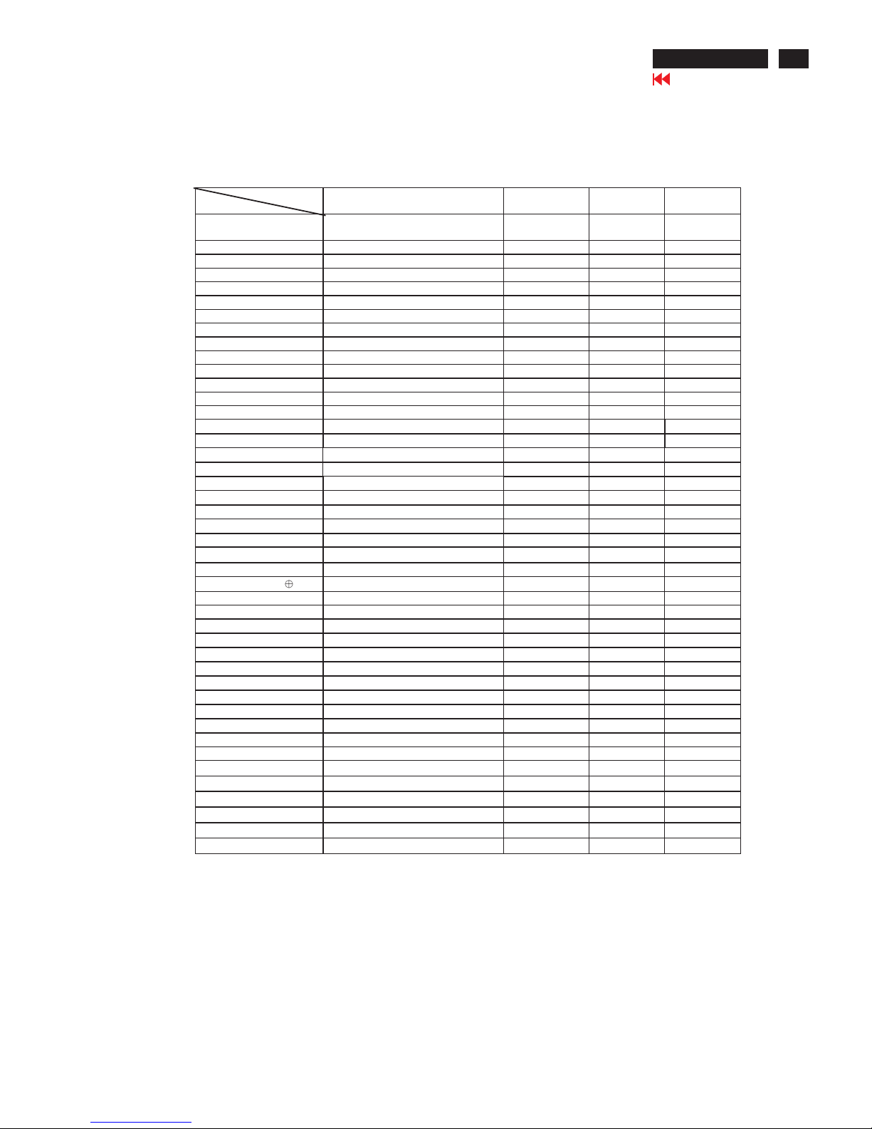
19
107T5
CRT
Item
Condition/Description CPT DAC
value
LG
DAC value
SDI
DAC value
9300/6500/sRGB
Bias
Nominal Cut -off setting
127 127 127
9300/6500/sRGB Gain Nominal Gain setting
185 185 185
sRGB contrast sRGB contrast
255 255 255
sRGB bright sRGB brightness
127 127 127
Corner -T, B Fh < 36KHz
134, 122 134, 126 136, 124
Corner -T, B 36KHz <Fh < 52KHz
134, 122 130, 126 130, 124
Corner -T, B 52KHZ < Fh <65KHz
140, 122 126, 126 130, 124
Corner -T, B Fh > 65KHz
140, 120 126, 126 128, 124
Pin Correction -T, B Top/Bottom pin correction
120, 126 122, 122 120, 120
Pin Correction -S, W S/W shape pin correction
130, 144 136, 130 130, 144
V-offset V-raster centering
65 60 90
V-gain V size control range for user
180 180 200
Sub-contrast 9300 peak light output adjust
220 220 220
Sub-brightness Brightness control range limit
160 160 160
Linearity -H
Fh < 33.00KHz
170 175 180
Linearity -H
33.00KHz < Fh < 36.00KHz
140 140 165
Linearity -H
36.00KHz < Fh < 40.00KHz
125 130 150
Linearity -H
40.00KHz < Fh < 45.00KHz
105 115 115
Linearity -H
45.00KHz < Fh < 52.00KHz
90 95 90
Linearity -H
52.00KHz < Fh < 55.00KHz
80 90 85
Linearity -H
55.00KHz < Fh < 60.50KHz
70 80 80
Linearity -H
60.50KHz < Fh < 66.00KHz
65 75 70
Linearity -H Fh >66.00 KHz
60 60 60
Linearity -V Vertical S -correction
50 50 50
Range-UserH H size control range for user
75 75 75
Range-Sub Zoom control range for user
55 55 55
B+ Adjusted for Anode voltage
89 89 89
ABL 9300 full white light o/p adjust
110 120 135
EHT comp -H, V
Fh < 33.00KHz
132, 114 132, 116 132, 114
EHT comp -H, V
33.00KHz < Fh < 36.00KHz
124, 114 130, 114 124, 114
EHT comp -H, V
36.00KHz < Fh < 40.00KHz
122, 116 126, 116 122, 114
EHT comp -H, V
40.00KHz < Fh < 45.00KHz
120, 116 124, 116 120, 116
EHT comp -H, V
45.00KHz < Fh < 52.00KHz
114, 116 118, 118 114, 116
EHT comp -H, V
52.00KHz < Fh < 55.00KHz
112, 116 118, 118 112, 116
EHT comp -H, V
55.00KHz < Fh < 60.50KHz
112, 116 116, 118 112, 116
EHT comp -H, V
60.50KHz < Fh < 66.00KHz
112, 118 114, 118 112, 118
EHT comp -H, V Fh >66.00 KHz
114, 118 114, 118 114, 118
V-Linbal Vertical top/bottom linearity
140 140 140
V-Focus Vertical focus amplitude
100 100 180
OSD Contrast OSD Contrast
255 255 255
LF-Brigh LightFrame Brightness
333
LF-Sharp LightFrame Sharpness
333
Moiré setting -H All modes
000
Moiré setting -V All modes
000

Electrical Instructions
X
Go to cover page
20
107T5
5.2 External degaussing Remove ferromagnetic measuring
equipment, Iron tablet, etc., in the neighbourhood of the
apparatus within half a meter. Position the set in E-W
direction and degauss well via external degaussing coil.
Slowly increase the distance between the picture tube and
Degaussing coil, keeping the coil in parallel with the
Screen of CRT. When the distance is more than 2m, turn
of f The degaussing current.
5.3 Adjustment mode: 68.7KHz/85Hz with correctly adjusted
video size 306x230mm. Use color-analyzer
(Minolta CA-100) to adjust cut-off and white balance.
Before alignment, set initial data as item 5.1 and
brightness set to 50%.
Setup A: 100x100mm white block , 0.7Vpp input video
signal, contrast at 0%, 9300 mode Calibrate CA100, Low
9300 RGB=100 x=0.283, y=0.297, Y=0.10FL 0.05FL
Setup B: 100x100mm white block , 0.7Vpp input video
signal, contrast at 100%, 9300 mode Calibrate Ca100,
High 9300 RGB=100 x=0.283, y=0.297, Y=41FL 1FL
Setup C: 100x100mm white block , 0.7Vpp input video
signal, contrast at 0%, 6500 mode Calibrate CA100, Low
6500 RGB=100 x=0.313, y=0.329, Y=0.10FL 0.05FL
Setup D: 100x100cm white block , 0.7Vpp input video signal,
contrast at 100%, 6500 mode Calibrate CA100, High 6500
RGB=100 x=0.313, y=0.329, Y=36FL 1FL
Setup E: 100x100mm white block , 0.7Vpp input video signal,
contrast at 0%, sRGB mode Calibrate CA100, Low sRGB
RGB=100 x=0.313, y=0.329, Y=0.10FL 0.05FL
Setup F: 100x100cm white block , 0.7Vpp input video signal,
contrast at 100%, sRGB mode Calibrate CA100, High
sRGB RGB=100 x=0.313, y=0.329, Y=36FL 1FL
Setup G: Full white (306x230mm), 0.7Vpp input video signal,
contrast at 100% , 9300 mode Calibrate CA100, High 9300
RGB=100 x=0.313, y=0.329, Y=30FL 1FL
5.3.1 Setup A, manually rotate Vg2 pot-meter on LOT until
brightness reaches 100 scale.
5.3.2 Setup A, adjust RGB cut-off (I C) for all colors at 100 7
scale, 9300 mode. (x=0.283, y=0.297, Y=0.10 0.05FL)
5.3.3 Setup B, adjust RGB gain (I C) for all colors at 100 2 scale,
9300 mode. (x=0.283, y=0.297, Y=41 0.5 FL)
5.3.4 Repeat 5.3.2, 5.3.3 (RGB cut-off and gain) to get both low
and high 9300 scales at 100. (0.10FL 0.05FL for low
scale; 41FL 1FL for high scale. x/y tolerance 0.005)
5.3.5 Setup C, adjust RGB cut-off (I C) for all colors at 100 7
scale, 6500 mode. (x=0.313, y=0.329, Y=0.10FL 0.05FL)
5.3.6 Setup D, adjust RGB gain (I C) for all colors at 100 2
scale, 6500 mode. (X=0.313, y=0.329, Y=36FL 1FL)
White alignment measurement equipment set-ups:
Adjustment procedure:
2
2
2
2
5.3.7 Repeat 5.3.5, 5.3.6 (RGB cut-off and gain) to get both low
and high 6500 scales at 100. (0.10FL 0.05FL for low scale;
36FL 1FL for high scale. x/y tolerance 0.005)
4.3.8 Setup E, adjust RGB cut-off (I C) for all colors at 100 7
scale, sRGB mode.
(x=0.313, y=0.329, Y=0.10FL 0.05FL)(same values as
6500 mode)
4.3.9 Setup F, adjust RGB gain (I C) for all colors at 100 2 scale,
sRGB mode.
(x=0.313, y=0.329, Y=36FL 1FL)(same values as 6500
mode)
5.3.10 sRGB brightness at 50%. Adjust sRGB contrast (I C) to get
Y=23FL 1FL for full white pattern.
(0.10FL 0.05FL for low scale, 23FL 1FL for high scale.
x/y tolerance 0.005)
5.4 Setup G, adjust ABL (I C) for 30FL 0.5FL, 9300 mode.
The above alignment method may be changed, as long as
the final results are the same.
(The above method has least amount of adjustment and
iteration steps.)
6.1 Alignment of primary geometry
2
2
2
2
6. Adjustment of the picture geometry
=========================
6.1.1 Apply Timing 7 (64KHz/60Hz, 1280x1024) with black video
signal, set V-position at 50%, set H and V-size for visible
raster edges at all sides.
(RGB cut-off can be increased temporarily to make raster
visible. After adjustment, restore RGB cut-off to original
values.) Slide switch 1603 for centered raster in horizontal
Direction. Adjust V-offset (I C) for centered raster in
vertical direction.
Apply Timing 8 (68.7kHz / 85Hz) with crosshatch signal and
start geometry alignment.
6.1.2 Adjust the Horizontal Size to 306mm.
6.1.3 Adjust the Horizontal Position for centered video.
6.1.4 Adjust the Vertical Size to 230 mm.
6.1.5 Adjust Vertical Position for centered video
6.1.6 Adjust picture tilt for correct TOP/BOTTOM lines.
(Picture tube should be mounted without tilt w.r.t. cabinet)
6.1.7 Adjust pincushion to get optimum vertical line.
6.1.8 Adjust trapezoid to get optimum vertical line.
6.1.9 Adjust balanced pincushion to get optimum vertical line.
6.1.10 Adjust the parallelogram to get optimum vertical line.
6.1.11 If needed, adjust the top / bottom corner control to get
optimum corner geometry.
Top and bottom corner only affect top and bottom 60mm of
the vertical lines.
(6.1.7, 6.1.8, 6.1.9 and 6.1.10 may need to be readjusted.)
6.1.12 Store the adjusted result and exit OSD.
(The values for pincushion, trapezoid, balance pincushion
and parallelogram can be copied to the other pre-set
modes to shorten alignment time.)
6.2 Other pre-set mode geometry adjustment
Use following procedure for all pre-set modes (except
68.7kHz/85Hz) (Timing Table1-8)
6.2.1 Adjust the Horizontal Size to 306mm.
6.2.2 Adjust the Horizontal Position to center position.
2
6.2.3 Adjust the Vertical Size to 230 mm.
6.2.4 Adjust the Vertical Position for correctly centred vertical
video.
6.2.5 Adjust pincushion to get optimum vertical line.
6.2.6 Adjust trapezoid to get optimum vertical line.
6.2.7 Adjust balanced pincushion to get optimum vertical line.
6.2.8 Adjust the parallelogram to get optimum vertical line.
(6.2.5, 6.2.6, 6.2.7 and 6.2.8 may need some iteration.)
6.2.9 Store the set result and exit OSD.
6.3 Other pre-load modes can be visible inside the bezel.
With full white pattern display at timing 68Khz /85Hz
1024x768, set brightness at 50% and adjust contrast to 25
FL at the center of the screen.
and adjust H and V focus pot-meters which are located at
flyback transformer, until H- and V-line focus is optimal over
the entire screen.
Apply full white pattern and adjust contrast till luminance
around 15FL. 1/3 area with minor moiré can be acceptable.
If needed, use moir cancellation function and adjust the
H- moir or V-moir to cancel the moiré defect, then save
at factory.
The DDC HEX data (refer to sheet-190) should be written
into the DDC by EEPROM writer or equivalent method.
The finished product should have the following default
Settings: Contrast: 100%, Brightness: 50%, Color: 9300,
Language: English(Chinese),
Power Save: On (Remark : Every mode is independent for
eset to factory setting.))
REFERENCE PATTERN GENERATOR : CHROMA 2135
* According to VESA version 1.0 release 0.6p
7 Focus adjustment
=============
8
8 Adjustment of Moir
================
9 Loading DDC code
=================
10 Default settings
==============
TIMING FOR V30 GS4 107T5 71K MODEL
X
Go to cover page
21
107T5
DDC Instructions
1. General
3. Pin assignment
Fig. 2 Alignment Kits
To Monitor
DC 8V~12V
Video Card
Video Card
To Printer
Power indicator
A. 15-pin D-Sub Connector
DDC Data Re-programming
In case the main EEPROM with which store all factory
settings were replaced because a defect,repaired monitor the serial
numbers have to be re-programmed.
It is advised to re-soldered the main EEPROM from
the old board onto the new board if circuit board have been replaced, in
this case the DDC data does not need to be re-programmed.
Additional information
Additional information about DDC (Display Data Channel) may be
obtained from Video Electronics Standards Association (VESA).
Extended Display Identification Data(EDID) information may be also
obtained from VESA.
DDC EDID structure
For the monitor : Standard Version 3.0
Structure Version 1.2
1. An i486 (or above) personal computer or compatible.
2. Microsoft operation system Windows 95/98.
4. Software DDC Alignment kits (4822 310 11184) shown as Fig. 2.
The kit contents: a. Alignment box x1
b. Printer cable x1
c. D-Sub cable x1
Note: The EDID301.EXE (Release Version 1.58, 20000818)is a
windows-based program, which cannot be run in MS-DOS.
Software DDC
with Software DDC
3. EDID301.EXE program (3138 106 10103) shown as Fig. 1
2. System and equipment requirements
Diskette with EDID301.EXE
EDID301.EXE
Figure 1
Ver:1.58
The 15-pin D-sub connector (male) of the signal cable
on the 3rd row for DDC feature :
1
10
6
11
15
5
Assignment
Assignment
Pin No.
Pin No.
Ground
Ground
Blue video input
2
7
6
8
4
5
3
1
9
12
11
14
13
15
10
Red video ground
Blue video ground
Green video ground
for selftest(PC ground)
Not connected - no.pin
Sync. Ground
Data clock line(SCL)
V.Sync(VCLK)
H.Sync
Bi-directional data(SDA)
Green video input
Red video input
X
Go to cover page
22
107T5
DDC Instructions
4. Configuration and procedure
There is no Hardware DDC (DDC IC) anymore. Main EEPROM stores
all factory settings and DDC data (EDID code) which is so called
Software DDC. The following section describes the connection and
procedure for Software DDC application. The main EEPROM can be reprobrammed by enabling "factory memory data write" function on the
DDC program (EDID301.EXE).
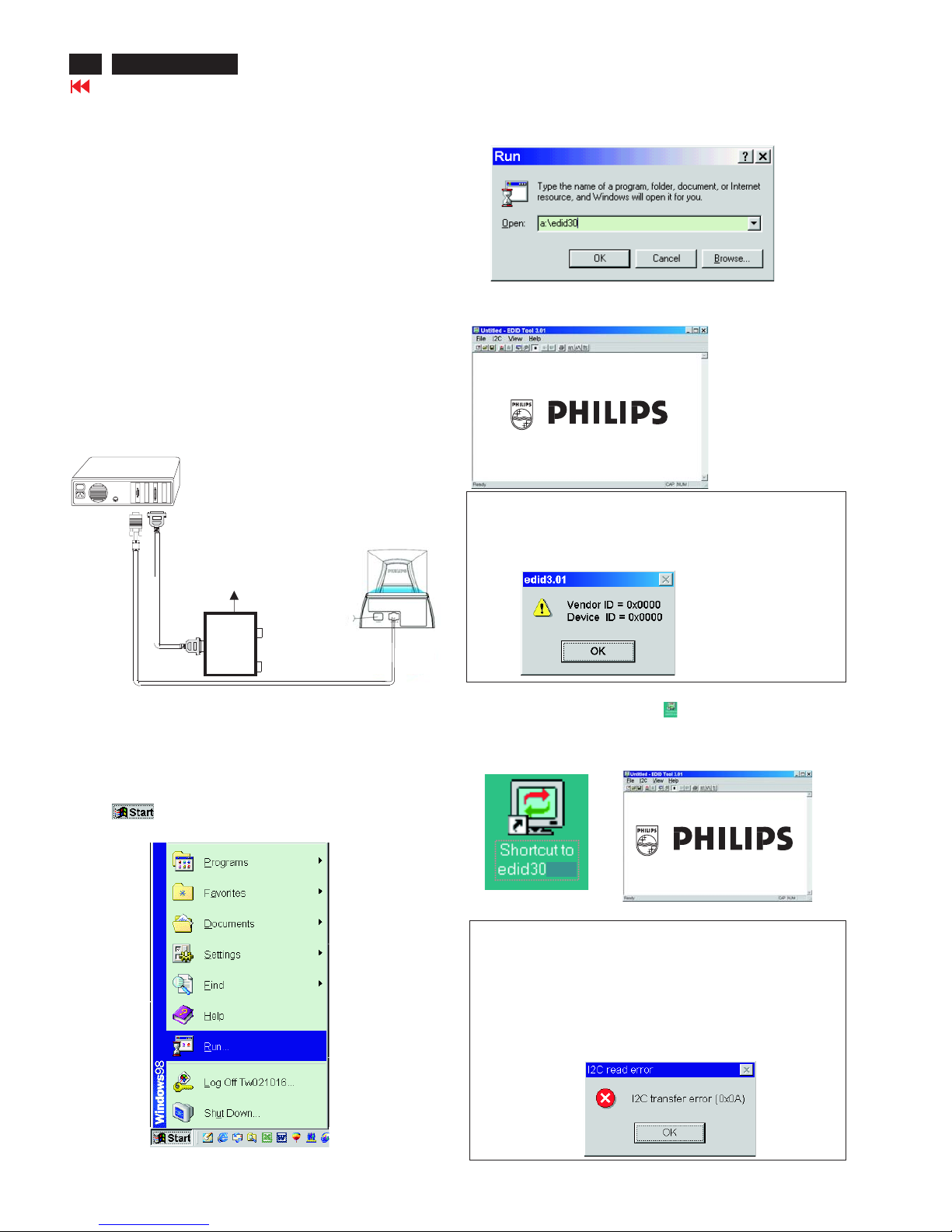
Step 3: Installation of EDID301.EXE
Method 1: Start on DDC program
Start Microsoft Windows.
1. Insert the disk containing EDID301.EXE program into floppy disk
drive.
2. Click , choose Run at start menu of Windows 95/98 as
shown in Fig. 4.
Fig. 4
*** INITIALIZE ALIGNMENT BOX ***
In order to avoid that monitor entering power saving mode due to
sync will cut off by alignment box, it is necessary to initialize
alignment box before re-programming DDC Data. Following steps
show you the procedures and connection.
Step 1
Step 2
: Supply 8~12V DC power source to the Alignment box by
plugging a DC power cord or using batteries.
: Connecting printer cable and video cable of monitor as
shown in Fig.3.
4. Click button. The main menu appears (as shown in Fig. 6).OK
This is for initialize alignment box.
Fig. 6
Fig. 5
Fig. 7
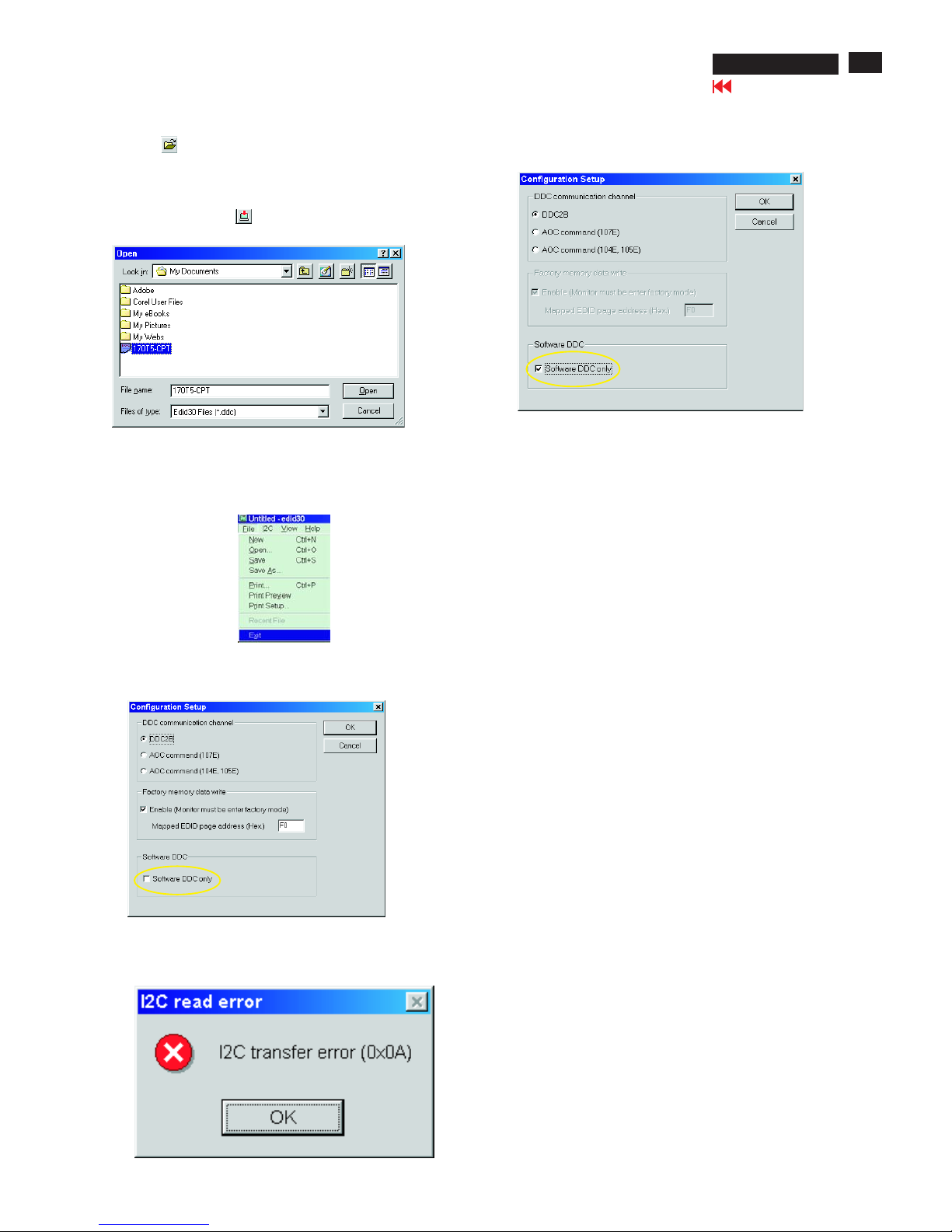
Note 1: If the connection is improper, you will see the following error
message (as shown in Fig. 7) before entering the main menu.
Meanwhile, the (read EDID) function will be disable. At this time,
please make sure all cables are connected correctly and fixedly,
and the procedure has been performed properly.
3. At the submenu, type the letter of your computer's floppy disk drive
followed by :EDID301 (for example, A:\EDID301, as shown in Fig. 5).
Method 2: After create a shortcut of EDID301.EXE
This is for initialize alignment box.
: Double click EDID301 icon (as shown in Fig. 8) which is
on the screen of Windows Wallpaper.
Bring up main menu of EDID301 as shown in Fig. 9.
Fig. 9
Note 2: During the loading, EDID301 will verify the EDID data which just
loaded from monitor before proceed any further function, once
the data structure of EDID can not be recognized, the following
error message will appear on the screen as below. Please
confirm following steps to avoid this message.
1. The data structure of EDID was incorrect.
2. DDC IC that you are trying to load data is empty.
3. Wrong communication channel has set at configuration setup
windows.
4. Cables loosed or poor contact of connection.
Fig. 8
1
Fig. 3
Rear view of the monitor
~
~
PC
To printer port (LTP1)
DC Power
8~12 V
Printer
Port
To video card
To
Monitor
To PC
Video cable
X
Go to cover page
23
107T5
DDC Instructions
Fig. 13
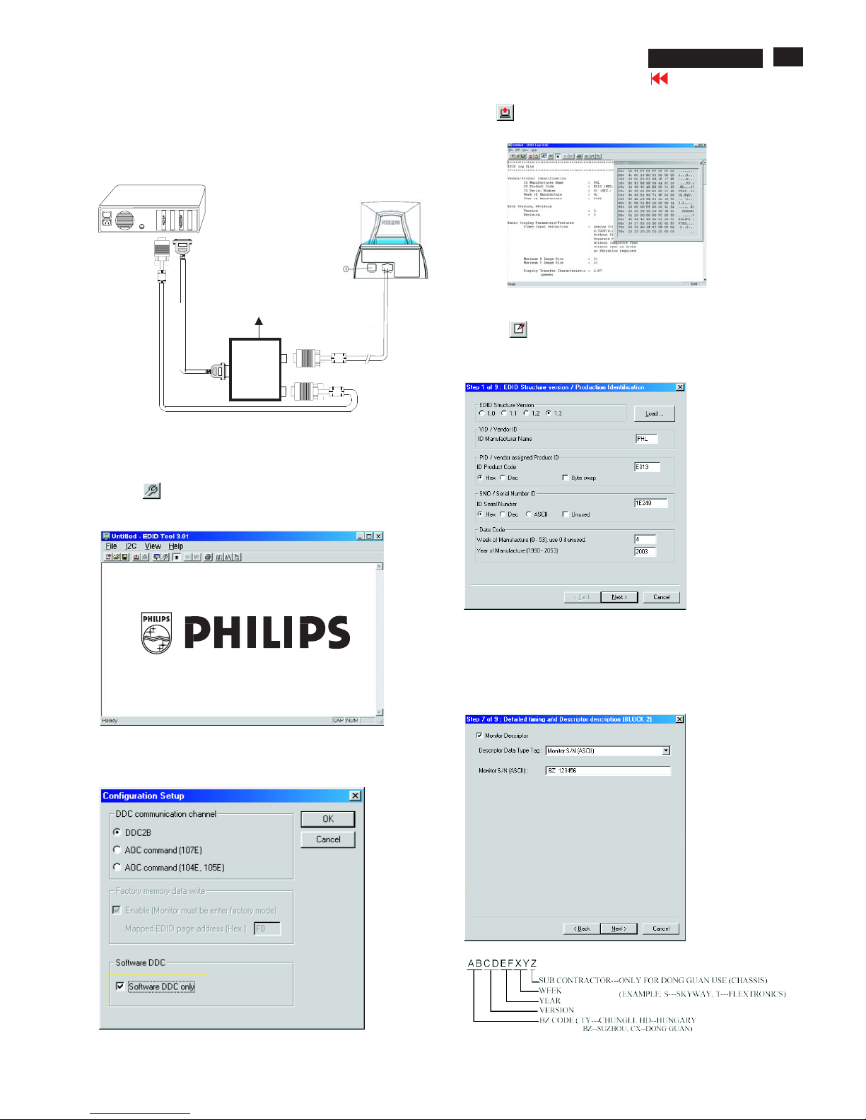
Re-programming EEPROM (Software DDC)
Step 1: After initialize alignment box, connecting all cables and
box as shown in Fig. 10
Fig. 11
Fig. 12
Step 2: Read DDC data from monitor
1-1 Click the left key of Mouse, or hit any key on the keyboard,
then the characters disappear from the screen.
1-2 Click icon as shown if Fig. 11 from the tool bar to bring up
the "Configuration Setup" windows as shown in Fig. 12.
2. Select the DDC2B as the communication channel.
Select " " & fill out " " for Mapped EDID page address
as shown in Fig. 12.
Enable F0
Step 3: Modify DDC data (verify EDID version, week, year)
1. Click (new function) icon from the tool bar, bring up
Step 1 of 9 as shown in Fig. 14 .
EDID301 DDC application provides the function selection and
text change (select & fill out) from Step 1 to Step 9.
Step 4: Modify DDC data (Monitor Serial No.)
Next
Next Finish
1. Click till the Step 7 of 9 window appears as shown in Fig. 15.
2. Fill out the new Serial No. (for example, TY 503960, TY 123456).
3. Click till the last step window appears, then click to exit
the Step window.
3. Click OK button to confirm your selection.
4. Click icon (Read EDID function) to read DDC EDID data from
monitor. The EDID codes will display on screen as shown in Fig. 13.
Fig. 14
Fig. 15
~
~
PC
To video card
To printer port (LTP1)
DC Power
8~12 V
Printer
Port
To
Monitor
To PC
Video cable
Fig. 10
Rear view of the monitor
X
Go to cover page
24
107T5
DDC Instructions
Fig. 16
Fig. 18
Step 8: Save DDC data
Sometimes, you may need to save DDC data as a text file for using
in other IC chip. To save DDC data, follow the steps below:
1. Click (Save) icon (or click "file"-> "save as") from the tool bar
and give a file name as shown in Fig. 19.
The file type is EDID301 file (*.ddc) which can be open in WordPad.
By using WordPad, the texts of DDC data & table (128 bytes, hex
code) can be modified. If DDC TEXTS & HEX Table are completely
correct, it can be saved as .ddc flie to re-load it into EEPROM for
DDC Data application.
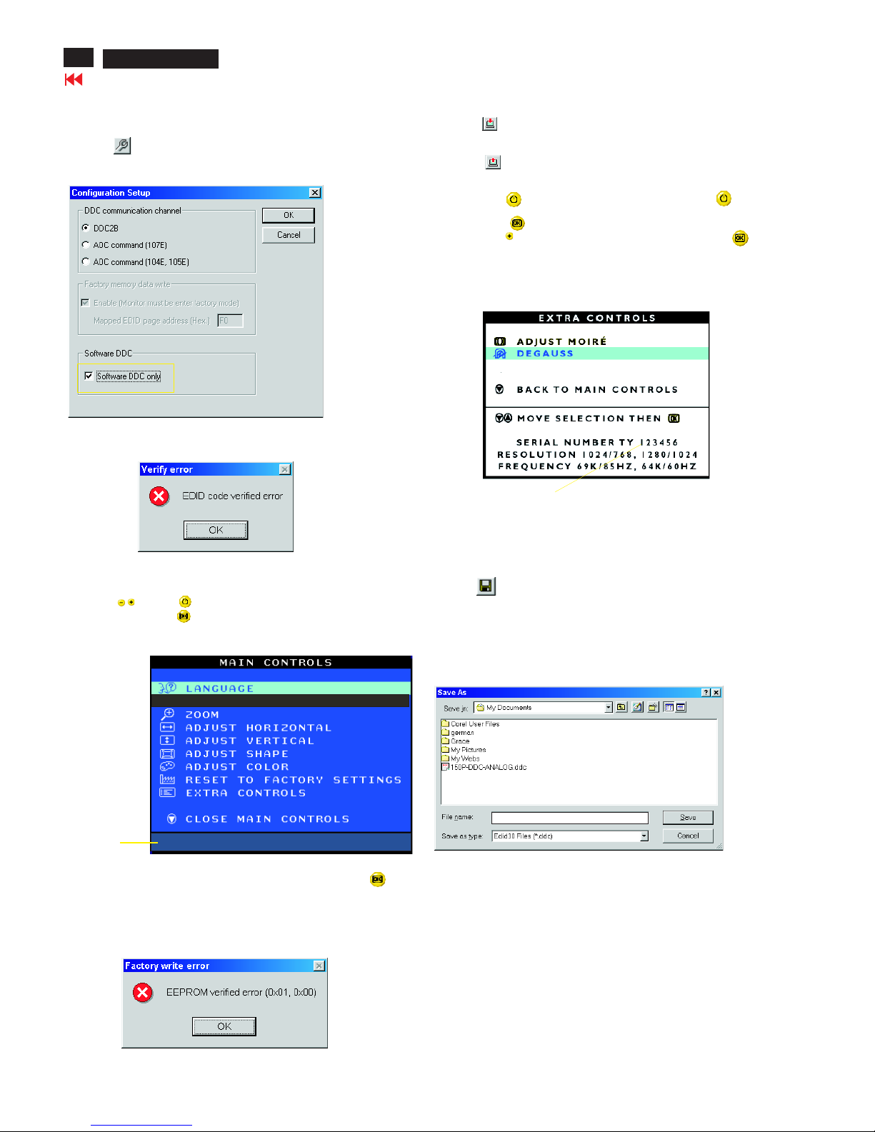
Step 5: **Configuration Setup & Enter Factory Mode **
for "write EDID data"
1. Click icon from the tool bar to bring up the Configuration Setup
windows again. Then, select "Software DDC only" as shown in
Fig. 16. Click "OK".
Step 6: Write DDC data
1. Click (Write EDID) icon from the tool bar to write DDC data.
Bring up "Writing 0%~100%, ready" a progressing bar on the left
down corner.
2. Click (Read EDID) to confirm it.
Step 7: Confirm Serial Number in User Mode
1. Press the button to turn off the monitor. Press the button
again to turn on the monitor.
2. Press the button to bring up the OSD Main Menu.
3. Press the button to select Extra Controls, press the
button to confirm your selection.
4. Confirm the Serial Number "123456" is updated
as shown in Fig. 18.
Fig. 19
If you do not select "Software DDC only", when you execute
"write EDID", it will bring up an error message as below.
If you do not access "Factory mode", when you execute
"write EDID", it will bring up an error message as below.
To access factory mode
1. Turn off monitor (don't turn off PC)
2. Press " " and " " simultaneously on the front control
panel,then press " ",wait till the OSD menu with characters
V30 10T5 P V2.01 20030110 (below OSD menu)" come on the
screen of monitor.
If OSD menu disappears on the screen of monitor, press " "
again (anytime), then the OSD menu comes on the screen again.
Fig. 17
MODEL SELECT
V30 107T5 P V.2.01 20030110
Factory
Mode
Indicator
2. Click .Save
107T5 V30
X
Go to cover page
25
107T5
DDC Instructions
Fig. 20
Fig. 22
Fig. 23
Fig. 21
Step 10: Exit DDC program
Pull down the File menu and select Exit as shown in Fig. 21.
(EDID Tool 3.01)
Step 9: Load DDC data
Open
1. Click from the tool bar.
2. Select the file you want to open as shown in Fig. 20.
3. Click .
4. Access "Factory Mode" and enable "Software DDC only" as shown
in Fig. 17 & Fig. 16.
5. Write EDID (click ).
Note1 : In User Mode: Read DDC data only
Software
DDC only was disabled
Before read EDID code, please confirm that the
as shown in Fig. 22.
Note2:InFactory Mode: Read/Write DDC data
Software DDC only was enabled
Before Read/Write EDID code, please confirm that the
as shown in Fig. 23.
If you do not disable "Software DDC only", when you execute
"read EDID", it will bring up an error message as below.

X
Go to cover page
26
107T5
Hex Data of DDC2B
**********************************************************************
EDID log file for CPT tube
**********************************************************************
Vendor/Product Identification
ID Manufacturer Name : PHL
ID Product Code : E013 (HEX.)
ID Serial Number : 1E240 (HEX.)
Week of Manufacture : 4
Year of Manufacture : 2003
EDID Version, Revision
Version : 1
Revision : 3
Basic Display Parameters/Features
Video Input Definition : Analog Video Input
0.700V/0.000V (0.70Vpp)
without Blank-to-Black Setup
Separate Sync
without Composite Sync
without Sync on Green
no Serration required
Maximum H Image Size : 31
Maximum V Image Size : 23
Display Transfer Characteristic : 2.86
(gamma)
Feature Support (DPMS) : Standby
Suspend
Active Off
Display Type : RGB color display
Color Characteristics
Red X coordinate : 0.631
Red Y coordinate : 0.329
Green X coordinate : 0.276
Green Y coordinate : 0.6
Blue X coordinate : 0.143
Blue Y coordinate : 0.057
White X coordinate : 0.283
White Y coordinate : 0.297
Established Timings
Established Timings I : 720 x 400 @70Hz (IBM,VGA)
640 x 480 @60Hz (IBM,VGA)
640 x 480 @72Hz (VESA)
640 x 480 @75Hz (VESA)
800 x 600 @60Hz (VESA)
Established Timings II : 800 x 600 @72Hz (VESA)
800 x 600 @75Hz (VESA)
832 x 624 @75Hz (Apple,Mac II)
1024 x 768 @60Hz (VESA)
1024 x 768 @70Hz (VESA)
1024 x 768 @75Hz (VESA)
Manufacturer's timings :
Standard Timing Identification #1
Horizontal active pixels : 640
Aspect Ratio : 4:3
Refresh Rate : 85
Standard Timing Identification #2
Horizontal active pixels : 800
Aspect Ratio : 4:3
Refresh Rate : 85
Standard Timing Identification #3
Horizontal active pixels : 1024
Aspect Ratio : 4:3
Refresh Rate : 85
Standard Timing Identification #4
Horizontal active pixels : 1280
Aspect Ratio : 5:4
Refresh Rate : 60
Standard Timing Identification #5
Horizontal active pixels : 640
Aspect Ratio : 4:3
Refresh Rate : 100
Standard Timing Identification #6
Horizontal active pixels : 800
Aspect Ratio : 4:3
Refresh Rate : 100
Standard Timing Identification #7
Horizontal active pixels : 1280
Aspect Ratio : 4:3
Refresh Rate : 60
Standard Timing Identification #8
Horizontal active pixels : 1152
Aspect Ratio : 4:3
Refresh Rate : 75
Detailed Timing #1
Pixel Clock (MHz) : 25.18
H Active (pixels) : 640
H Blanking (pixels) : 160
V Active (lines) : 350
V Blanking (lines) : 99
H Sync Offset (F Porch) (pixels) : 16
H Sync Pulse Width (pixels : 96
V Sync Offset (F Porch) (lines) : 37
V Sync Pulse Width (lines) : 2
H Image Size (mm) : 306
V Image Size (mm) : 230
H Border (pixels) : 0
V Border (lines) : 0
Flags : Non-interlaced
: Normal Display, No stereo
: Digital Separate sync.
: Negative Vertical Sync.
: Positive Horizontal Sync.
Monitor Descriptor #2
Serial Number : BZ 123456
Monitor Descriptor #3
Monitor Name : PHILIPS 107T5
Monitor Descriptor #4
Monitor Range Limits
Min. Vt rate Hz : 50
Max. Vt rate Hz : 160
Min. Horiz. rate kHz : 30
Max. Horiz. rate kHz : 71
Max. Supported Pixel : 110
No secondary GTF timing formula supported.
Extension Flag : 0
Check sum : 7D (HEX.)
**********************************************************************
EDID data (128 bytes)
*********************************************************************
0: 00 1: ff 2: ff 3: ff 4: ff 5: ff 6: ff 7: 00
8: 41 9: 0c 10: 13 11: e0 12: 40 13: e2 14: 01 15: 00
16: 04 17: 0d 18: 01 19: 03 20: 68 21: 1f 22: 17 23: ba
24: e8 25: 9e 26: a8 27: a1 28: 54 29: 46 30: 99 31: 24
32: 0e 33: 48 34: 4c 35: ad 36: ee 37: 00 38: 31 39: 59
40: 45 41: 59 42: 61 43: 59 44: 81 45: 80 46: 31 47: 68
48: 45 49: 68 50: 81 51: 40 52: 71 53: 4f 54: d6 55: 09
56: 80 57: a0 58: 20 59: 5e 60: 63 61: 10 62: 10 63: 60
64: 52 65: 08 66: 32 67: e6 68: 10 69: 00 70: 00 71: 1a
72: 00 73: 00 74: 00 75: ff 76: 00 77: 20 78: 42 79: 5a
80: 20 81: 20 82: 31 83: 32 84: 33 85: 34 86: 35 87: 36
88: 0a 89: 20 90: 00 91: 00 92: 00 93: fc 94: 00 95: 50
96: 48 97: 49 98: 4c 99: 49 100: 50 101: 53 102: 20 103: 31
104: 30 105: 37 106: 54 107: 35 108: 00 109: 00 110: 00 111: fd
112: 00 113: 32 114: a0 115: 1e 116: 47 117: 0b 118: 00 119: 0a
120: 20 121: 20 122: 20 123: 20 124: 20 125: 20 126: 00 127: 74

X
Go to cover page
27
107T5
Hex Data of DDC2B
**********************************************************************
EDID log file for LG tube
**********************************************************************
Vendor/Product Identification
ID Manufacturer Name : PHL
ID Product Code : E013 (HEX.)
ID Serial Number : 1E240 (HEX.)
Week of Manufacture : 4
Year of Manufacture : 2003
EDID Version, Revision
Version : 1
Revision : 3
Basic Display Parameters/Features
Video Input Definition : Analog Video Input
0.700V/0.000V (0.70Vpp)
without Blank-to-Black Setup
Separate Sync
without Composite Sync
without Sync on Green
no Serration required
Maximum H Image Size : 31
Maximum V Image Size : 23
Display Transfer Characteristic : 2.83
(gamma)
Feature Support (DPMS) : Standby
Suspend
Active Off
Display Type : RGB color display
Color Characteristics
Red X coordinate : 0.636
Red Y coordinate : 0.327
Green X coordinate : 0.278
Green Y coordinate : 0.6
Blue X coordinate : 0.145
Blue Y coordinate : 0.064
White X coordinate : 0.283
White Y coordinate : 0.297
Established Timings
Established Timings I : 720 x 400 @70Hz (IBM,VGA)
640 x 480 @60Hz (IBM,VGA)
640 x 480 @72Hz (VESA)
640 x 480 @75Hz (VESA)
800 x 600 @60Hz (VESA)
Established Timings II : 800 x 600 @72Hz (VESA)
800 x 600 @75Hz (VESA)
832 x 624 @75Hz (Apple,Mac II)
1024 x 768 @60Hz (VESA)
1024 x 768 @70Hz (VESA)
1024 x 768 @75Hz (VESA)
Manufacturer's timings :
Standard Timing Identification #1
Horizontal active pixels : 640
Aspect Ratio : 4:3
Refresh Rate : 85
Standard Timing Identification #2
Horizontal active pixels : 800
Aspect Ratio : 4:3
Refresh Rate : 85
Standard Timing Identification #3
Horizontal active pixels : 1024
Aspect Ratio : 4:3
Refresh Rate : 85
Standard Timing Identification #4
Horizontal active pixels : 1280
Aspect Ratio : 5:4
Refresh Rate : 60
Standard Timing Identification #5
Horizontal active pixels : 640
Aspect Ratio : 4:3
Refresh Rate : 100
Standard Timing Identification #6
Horizontal active pixels : 800
Aspect Ratio : 4:3
Refresh Rate : 100
Standard Timing Identification #7
Horizontal active pixels : 1280
Aspect Ratio : 4:3
Refresh Rate : 60
Standard Timing Identification #8
Horizontal active pixels : 1152
Aspect Ratio : 4:3
Refresh Rate : 75
Detailed Timing #1
Pixel Clock (MHz) : 25.18
H Active (pixels) : 640
H Blanking (pixels) : 160
V Active (lines) : 350
V Blanking (lines) : 99
H Sync Offset (F Porch) (pixels) : 16
H Sync Pulse Width (pixels) : 96
V Sync Offset (F Porch) (lines) : 37
V Sync Pulse Width (lines) : 2
H Image Size (mm) : 306
V Image Size (mm) : 230
H Border (pixels) : 0
V Border (lines) : 0
Flags : Non-interlaced
: Normal Display, No stereo
: Digital Separate sync.
: Negative Vertical Sync.
: Positive Horizontal Sync.
Monitor Descriptor #2
Serial Number : BZ 123456
Monitor Descriptor #3
Monitor Name : PHILIPS 107T5
Monitor Descriptor #4
Monitor Range Limits
Min. Vt rate Hz : 50
Max. Vt rate Hz : 160
Min. Horiz. rate kHz : 30
Max. Horiz. rate kHz : 71
Max. Supported Pixel : 110
No secondary GTF timing formula supported.
Extension Flag : 0
Check sum : 9B (HEX.)
**********************************************************************
EDID data (128 bytes) for LG tube
**********************************************************************
0: 00 1: ff 2: ff 3: ff 4: ff 5: ff 6: ff 7: 00
8: 41 9: 0c 10: 13 11: e0 12: 40 13: e2 14: 01 15: 00
16: 04 17: 0d 18: 01 19: 03 20: 68 21: 1f 22: 17 23: b7
24: e8 25: f6 26: 28 27: a2 28: 53 29: 47 30: 99 31: 25
32: 10 33: 48 34: 4c 35: ad 36: ee 37: 00 38: 31 39: 59
40: 45 41: 59 42: 61 43: 59 44: 81 45: 80 46: 31 47: 68
48: 45 49: 68 50: 81 51: 40 52: 71 53: 4f 54: d6 55: 09
56: 80 57: a0 58: 20 59: 5e 60: 63 61: 10 62: 10 63: 60
64: 52 65: 08 66: 32 67: e6 68: 10 69: 00 70: 00 71: 1a
72: 00 73: 00 74: 00 75: ff 76: 00 77: 20 78: 42 79: 5a
80: 20 81: 20 82: 31 83: 32 84: 33 85: 34 86: 35 87: 36
88: 0a 89: 20 90: 00 91: 00 92: 00 93: fc 94: 00 95: 50
96: 48 97: 49 98: 4c 99: 49 100: 50 101: 53 102: 20 103: 31
104: 30 105: 37 106: 54 107: 35 108: 00 109: 00 110: 00 111: fd
112: 00 113: 32 114: a0 115: 1e 116: 47 117: 0b 118: 00 119: 0a
120: 20 121: 20 122: 20 123: 20 124: 20 125: 20 126: 00 127: 9b

X
Go to cover page
28
107T5
Hex Data of DDC2B
**********************************************************************
EDID log file for SDI tube
**********************************************************************
Vendor/Product Identification
ID Manufacturer Name : PHL
ID Product Code : E013 (HEX.)
ID Serial Number : 1E240 (HEX.)
Week of Manufacture : 4
Year of Manufacture : 2003
EDID Version, Revision
Version : 1
Revision : 3
Basic Display Parameters/Features
Video Input Definition : Analog Video Input
0.700V/0.000V (0.70Vpp)
without Blank-to-Black Setup
Separate Sync
without Composite Sync
without Sync on Green
no Serration required
Maximum H Image Size : 31
Maximum V Image Size : 23
Display Transfer Characteristic : 2.9
(gamma)
Feature Support (DPMS) : Standby
Suspend
Active Off
Display Type : RGB color display
Color Characteristics
Red X coordinate : 0.645
Red Y coordinate : 0.316
Green X coordinate : 0.265
Green Y coordinate : 0.606
Blue X coordinate : 0.143
Blue Y coordinate : 0.058
White X coordinate : 0.283
White Y coordinate : 0.297
Established Timings
Established Timings I : 720 x 400 @70Hz (IBM,VGA)
640 x 480 @60Hz (IBM,VGA)
640 x 480 @72Hz (VESA)
640 x 480 @75Hz (VESA)
800 x 600 @60Hz (VESA)
Established Timings II : 800 x 600 @72Hz (VESA)
800 x 600 @75Hz (VESA)
832 x 624 @75Hz (Apple,Mac II)
1024 x 768 @60Hz (VESA)
1024 x 768 @70Hz (VESA)
1024 x 768 @75Hz (VESA)
Manufacturer's timings :
Standard Timing Identification #1
Horizontal active pixels : 640
Aspect Ratio : 4:3
Refresh Rate : 85
Standard Timing Identification #2
Horizontal active pixels : 800
Aspect Ratio : 4:3
Refresh Rate : 85
Standard Timing Identification #3
Horizontal active pixels : 1024
Aspect Ratio : 4:3
Refresh Rate : 85
Standard Timing Identification #4
Horizontal active pixels : 1280
Aspect Ratio : 5:4
Refresh Rate : 60
Standard Timing Identification #5
Horizontal active pixels : 640
Aspect Ratio : 4:3
Refresh Rate : 100
Standard Timing Identification #6
Horizontal active pixels : 800
Aspect Ratio : 4:3
Refresh Rate : 100
Standard Timing Identification #7
Horizontal active pixels : 1280
Aspect Ratio : 4:3
Refresh Rate : 60
Standard Timing Identification #8
Horizontal active pixels : 1152
Aspect Ratio : 4:3
Refresh Rate : 75
Detailed Timing #1
Pixel Clock (MHz) : 25.18
H Active (pixels) : 640
H Blanking (pixels) : 160
V Active (lines) : 350
V Blanking (lines) : 99
H Sync Offset (F Porch) (pixels) : 16
H Sync Pulse Width (pixels) : 96
V Sync Offset (F Porch) (lines) : 37
V Sync Pulse Width (lines) : 2
H Image Size (mm) : 306
V Image Size (mm) : 230
H Border (pixels) : 0
V Border (lines) : 0
Flags : Non-interlaced
: Normal Display, No stereo
: Digital Separate sync.
: Negative Vertical Sync.
: Positive Horizontal Sync.
Monitor Descriptor #2
Serial Number : BZ 123456
Monitor Descriptor #3
Monitor Name : PHILIPS 107T5
Monitor Descriptor #4
Monitor Range Limits
Min. Vt rate Hz : 50
Max. Vt rate Hz : 160
Min. Horiz. rate kHz : 30
Max. Horiz. rate kHz : 71
Max. Supported Pixel : 110
No secondary GTF timing formula supported.
Extension Flag : 0
Check sum : F1 (HEX.)
**********************************************************************
EDID data (128 bytes) for SDI tube
**********************************************************************
0: 00 1: ff 2: ff 3: ff 4: ff 5: ff 6: ff 7: 00
8: 41 9: 0c 10: 13 11: e0 12: 40 13: e2 14: 01 15: 00
16: 04 17: 0d 18: 01 19: 03 20: 68 21: 1f 22: 17 23: be
24: e8 25: 0d 26: b8 27: a5 28: 51 29: 43 30: 9b 31: 24
32: 0e 33: 48 34: 4c 35: ad 36: ee 37: 00 38: 31 39: 59
40: 45 41: 59 42: 61 43: 59 44: 81 45: 80 46: 31 47: 68
48: 45 49: 68 50: 81 51: 40 52: 71 53: 4f 54: d6 55: 09
56: 80 57: a0 58: 20 59: 5e 60: 63 61: 10 62: 10 63: 60
64: 52 65: 08 66: 32 67: e6 68: 10 69: 00 70: 00 71: 1a
72: 00 73: 00 74: 00 75: ff 76: 00 77: 20 78: 42 79: 5a
80: 20 81: 20 82: 31 83: 32 84: 33 85: 34 86: 35 87: 36
88: 0a 89: 20 90: 00 91: 00 92: 00 93: fc 94: 00 95: 50
96: 48 97: 49 98: 4c 99: 49 100: 50 101: 53 102: 20 103: 31
104: 30 105: 37 106: 54 107: 35 108: 00 109: 00 110: 00 111: fd
112: 00 113: 32 114: a0 115: 1e 116: 47 117: 0b 118: 00 119: 0a
120: 20 121: 20 122: 20 123: 20 124: 20 125: 20 126: 00 127: f1
29
9
Go to cover page
107T5
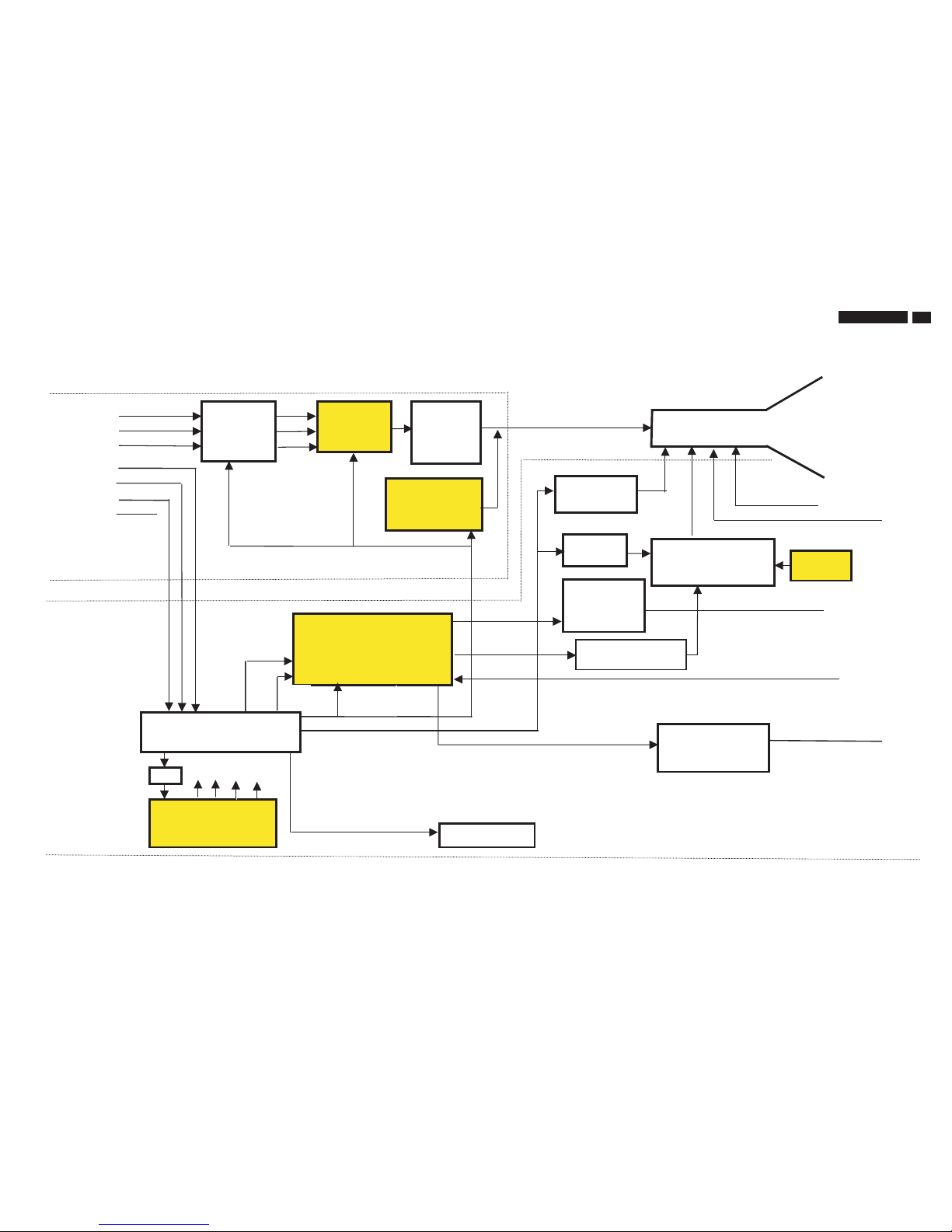
Function Block of V30 107T5
R
G
B
H
SDA
SCL
V
Self-
test
PREAMP
with OSD
NT6812
ROTATION
BC516+BC517
H-OUTPUT/
BU2527AF/DM32F5
/TIP122
VERTICAL
OUTPUT STAGE
TDA8172
VIDEO
HORIZONTZL & VERTICAL
SYNC PROCESSOR
& B+ CONTROLLER
TDA 9112A
KEY
CONTROL
&
LED
MICRO-PROCESSOR
MCU WT62P2
SWITCH MODE
POWER SUPPLY
TEA1507
OFF
DEGAUSSING
EEPROM
M24C04
-BN6
S-CAP
SWITCH
DC
O/P
MAIN
BOARD
AC
INPUT
MIC I/P
(30-71KHz)
H
V
I2C control
EHT Compensation
H-Driver
BSN254A
EHT
G1, G2
FOCUS
FOCUS
LOT
CF2091
LIGHT
FRAME IC
TDA4823
I2C
BUCK
CONVERTER
MTP5P25
DC
RESTORATION
LM2480
I2C
VIDEO
OUTPUT
STAGE
STV9556
R/G/B
CRT
30
107T5
9
Go to cover page
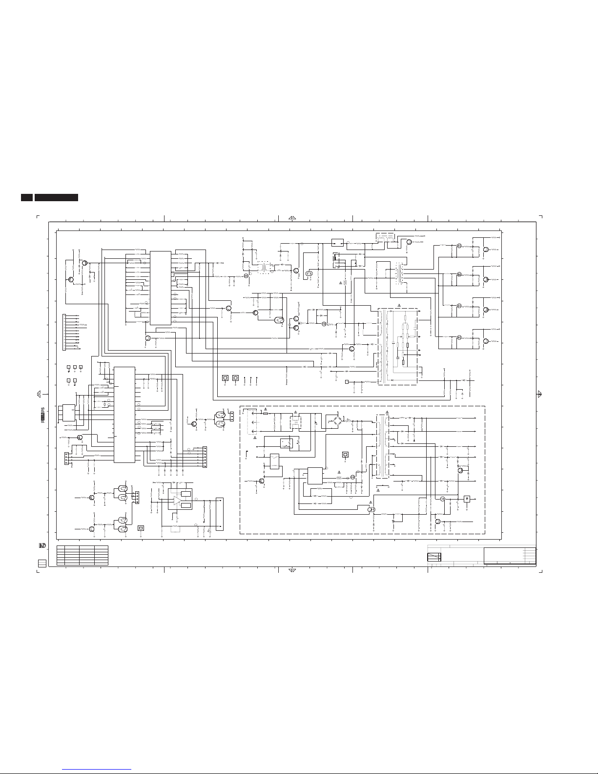
Schematic Diagram of Main board
+t
Rs
Rp
+t
COM
/PWM7
/HOUT
/VOUT
/PWM13
/PWM12
/PWM11
/PWM10
/PWM9
/PWM8
/SCL1
/SAD1
/AD0
/AD1
/AD2
/CLAMP
/3V3
/HFI
/HFO
/SDA2
/SCL2
/PAT
/SOGIN
/AD3
/PWM4
/PWM5
/PWM6
F2
G2
EHT
White
Red
Grey
F1
C
POWER
AMPLIFIER
_
+
FLYBACK
GENERATOR
THERMAL
PROTECTION
2252
2255
2633
2637
3408
3409
910N250V MPS
820N250V MPS
820N250V MPS
330N400V MPSA 300N400V MPSA
300N400V MPSA
270P2KVX7R
270P2KVX7R
330P2KVX7R
330P2KVX7R
330P2KVX7R
330P2KVX7R
2R2 1/2W
2R2 1/2W
2R2 1/2W
7102K13
7103L10
7105M16
7151L19
7503C1
7262A20
7263B20
7264D20
7266E20
7602D9
7603D10
7604E11
7605B12
7606A17
7613D12
6603B11
6604B8
6605B12
6606A15
6607B15
6608A11
6609G20
6611D13
7615E13
7616F15
7801F4
6251A20
V30-107T5CRT Deviationlist *
REF. LG Tube SDI Tube CPT Tube
E
8813F2
8814G1
8815G1
9625E15
9626E15
S001E18
6803L6
6804L6
7154N19
7155N16
7252A21
7253B21
7254D21
7256E21
N
F1D1
F2D1
F3D1
F4E1
F5E1
F6E1
F7E1
7405M2
7406L3
7407M3
7401N7
2R2 1/2W
2R4 1/2W
2R4 1/2W
6805L7
7101L15
6159M19
6160N18
6161N16
6162L17
7504E5
7601C9
6502B2
6503F13
6504B2
6507G13
6601C9
6602A9
6612F15
6613G14
6614E14
7802H1
6252B20
6253D20
8812F1
C
D
[R]
N
A
B
1/2W
+350V
[R] STANDSFORCOMPONENT RESERVED.
7152M19
7153M20
H
I
J
K
L
M
10 11 12 13 14 15 16 17
F8E1
F9E1
F10E1
7408N2
7402J7
7403I8
7404I8
7614E12
6158L19
8910
6255E20
6401L6
19 20 21
A
B
C
D
E
123
6615D13
7803J2
8501F1
8601H14
8811F1
1/2W
1/2W
[R]
1/2W
DDC5V
1%
F
G
[R]
1%
1%
9
F23K7
F24K7
F25K7
F26K7
F27I10
F29J10
F30I14
F31I14
18 19 20
F11F1
7409N3
7410N3
7501A5
7502B2
RMU
567
BEAD
BEAD
1/2W
13 14 15 16 17 18
F44K16
F45K16
F46L16
1101J10
1102 I10
1103K11
1104K10
1105-AJ10
F
G
H
4
6616G12
6617H20
6801K6
6802L6
1/2W
DDCSCL
1/4W
[R]
1/2W
1/2W 1%
PB:57271
F17M4
F18M4
F19M4
F20J7
F21K7
F22K7
1605G10
1801H3
1802J7
1803K1
2101I11
2103I13
2104I13
2105I14
F32I14
F33J14
F34J15
21
F12F1
F13K1
F14K1
F15K1
1%
BEAD
1%
[R]
1%
2154K19
2155K19
2156L19
11 12
[R]
POWER SUPPLY
F40I16
F41J16
F42J16
F43J16
2252A19
2255C17
2256B20
2257B19
2261D20
2262D19
2271E20
2272E19
1105-BK10
1109B13
1401I9
I
5678
-200V
[R]
1/2W
2W
1%
F16K1
1/2W 1%
1/4W
1/2W
1/2W
1604G10
2505C4
2506C4
2507C4
2508B4
2509D4
2511F13
2512D4
2513B6
2106K10
2107I15
2108L15
F35J15
1234
+800V
RMU
2151L17
2152I17
2153J17
2605D8
2606D11
2607C12
BEAD
[R]
2160M19
2161N17
2162N19
2163K20
2164K20
2251A20
2616D10
2617B8
2618E15
2625F15
2626F13
2627C10
2628E12
2629E14
2401L5
2402L6
2403M5
1402L4
J
K
L
M
AC+1000V
1/2W
-200V
MPSA
[R]
2802H2
2803H2
1%
1/2W
2410M3
2411N3
2501A4
2502B4
2503B4
2504B4
2814K1
2815I6
3101I11
3102I11
3103I15
3104L14
3105L13
3106L14
2514B6
2515C6
2516D6
2109L14
F36I15
F37K15
F38K15
F39I16
1/2W
1/2W
[R]
Hin
2604B2
1/2W
1%
1/4W
2157M18
2158M18
2610B13
2611A14
2612A15
2613B15
2614C14
2615A17
3154K20
3155N16
3156N16
3157M18
3158M18
3159M18
3160N19
3161N18
2630G14
2631H19
2632A11
2404N6
1601-AA14
1601-CM8
1601-DN8
1603G9
1/4W
1W
1/2W
1/4W
[R]
SB:57251x1
1%
[R]
2W
1/2W
2806G5
2807I5
2808I5
2809J5
2810L5
2813K2
[R]
3257B21
3258B20
3259B19
3261B20
3264B21
3266D20
3267D19
3107L14
3108L14
3109L15
2517D6
2110L12
2111L11
2112L16
2113L10
[R]
[R]
[R]
[R]
[R]
3504B2
3505B2
3506B4
2804I2
2805G5
1/2W
1/4W
1/4W
MAIN PCB
DDCSDA
1/2W
3515E6
3516E5
3517E6
3518B1
3519B1
3520A6
3521A6
3522B6
3268D20
3269C21
3272D21
3110L13
2405N5
2406N6
2408M7
2409I7
1/2W
[R]
1/2W
1%
+1200V
3603C9
3604B9
3606B9
3115I14
3116J12
3403M5
3404N6
3406N7
3407M8
3408N7
3409N7
3615D11
3616C14
3617A15
3618A18
3619A18
3620A17
3621C11
3622H20
3419N2
3420N3
3421N3
3251A21
2634A11
2636A12
2637B16
2801H2
1/2W
+70V
+160V
1%
3503C2
3638E13
3640F13
3641F14
[R]
1/2W
3509C4
3510C4
3511E2
3512D5
3513D5
3514D4
3657B15
3658D18
3801G2
3802H2
3803H2
3804H2
3805I1
3806J1
3523C6
3524C6
3526C1
3281E20
3111M13
3112M13
3113L12
3114L10
[R]
[R]
Vin
1/2W
1/2W
3817K5
3818K5
3819K2
3401L5
3402M5
3609C10
3610C10
3611C11
3612C10
3613D8
3614D9
3828I5
4101K14
4401N4
4601G9
4602G8
5101I12
5102K15
5103I17
3623E11
3624G15
3625H15
3422I7
3252A20
3253A20
3254A19
3256A21
[R]
+1200V
3632B7
3633D12
3636D13
selftest
[R]
H-yoke
3507A4
3508A5
3644F15
3648G19
3652H19
3653H19
3655B16
3656B16
5612E14
5613D9
5671B17
6101I14
6102K15
6103L15
6104M13
6105M13
3807G5
3808G5
3809I5
3527C1
3282E19
3283E20
3284E21
3286E21
1/2W
1/4W
[R]
3815K2
3816J6
3607B11
3608B12
3822G3
3823J1
3824J1
3825G3
3826G5
3827G5
E
D
C
B
A
5151I20
5152J20
5153J20
3626G15
3423M2
3424N2
3501A2
3502B2
3W
1/2W
V-yoke
1/4W
1/2W
3642F14
3643F15
5606B14
5607B14
5608A15
5609A15
5610D16
5611E14
12 13 14 2827262524
6106L10
6151I17
6152J17
3810J5
3528E5
3529C7
3601B8
3602B8
[R]
P
O
N
3820K2
3821G3
7654321 28
5154K19
3627A9
3628G11
3629A10
3631G20
1/2W
123
5604B13
5605C13
S
R
Q
P
O
N
M
L
6153J17
3811J5
3812J5
3813J5
3814K5
T
S
R
Q
E
D
C
K
J
I
H
G
F
A
owner.
isprohibited withoutthewritten consentofthe copyright
Allrights reserved.Reproductionin wholeorin parts
toestemmingvan deauteursrechthebbende.
gedeeltelijk,is niettoegestaandan metschriftelijke
Allerechten voorbehouden.Verveelvuldiging,geheel of
14
5156I16
5601B10
5602B11
5603A13
18171615
T
27262423222120
K
4567891011
B
2322
6154J19
6155K19
6156K19
6157L20
15
I
H
G
F
1716
13
M
L
[R]
*
*
*
**
*
21201918
1211 19
2608A13
2609D14
3117L19
3118M18
3119L18
3124K11
3152I18
3153J17
3410N8
3412I7
3413I7
3414I8
3415M5
3416L2
3417M3
3418M3
3162N18
3163N19
3164N20
1098
TOVIDEO BOARD831
1
TOCTRLBD8899
TOI /F CABLE
TOROTATION
25
J
+6
[R]
[R]
[R]
[R]
[R]
[R]
[R]
[R]
[R]
[R]
[R]
[R]
[R]
[R]
2518G13
2601H15
2602B10
2603A10
1/2W
GND
1/2W
1/2W
1/2W
2633C16
[R]
1/4W
8601
1
3424
3821
8K2
7604
TIP122
5153
100u
3812
4K7
6105
BAV21
+5
3617
100R
BZX79-B5V6
6804
3632
1K
3251
3K3
+6
F37
F4
+12
D9R0MC
3124
3
2
1
S001
Sparkgap1.8 mm
+12
F24
3801
3K3
BC548C
7254
2151
4u7
100
BAV21
6607
3K3
BC516
7410
15R
3104
3257
8811
1
+83
3631
10K
7153
L78L05ACZ
GND2
IN
1
OUT
3
2106
2n2
2103
250
6803
BZX79-B5V6
2271
SB140
6154
3820
22K
4M7
3642
3284
2155
1000u
16
3641
39K
10n
2618
100
100MHZ
5103
100MHZ
3281
5612
3604
47R
MPSA44
7616
6155
BYV27-200
22K
F10
15R
3616
3611
100K
3657
250
22u
2609
7101
SSS7N60B
3809
10K
25
10u
2511
25
2u2
2251
7256
EGP20G
6614
3511
1K5
4K7
3802
3619
1K
3mH
5611
3286
100n
2617
50
470K
3102
JFE63931
1603
1
U
4601
TBC338-40
7103
150n
2607
100
F39
22K
3653
1
2
3
4
5
6
7
3404
2K2
100n
2261
50
1802
26041
10K
3413
5152
100u
1001u
2602
+6
100MHZ
5602
6401
SBYV27-200
4K7
3506
100R
3422
7407
BZX55-B5V6
6802
3154
2K2
F13
10n
250
2112
2n2
7405
250
2613
33K
3261
3608
10R
9625
3256
22K
100u
5609
3415
3K9
2257
250330n
3157
100K
3272
22K
7603
BC558C
1N4148
6617
1104
JFE632011
7614
BC328-40
5608
HL2455H-057N
2
3
4
5
+6
220p
2108
2000
50
2804
22p
100n
100
2515
F26
10K
3505
7601
+5
6601
1N4148
3266
22R
BSN254A
3113
1K
6255
3401
2R2
7504
PH2369
5601
1
3
42
3805
100R
F5
SCK104
3115
1604
JFE63931
1
2815
2u2
50
3158
2K2
220n
2109
100
254u7
2626
1K
3624
100
2503
10n
3515
180K
3613
1K
6106
1N4148
BAV21
6608
22n
2810
50
10K
3528
3602
1K
3504
3825
8K2
2632
3n3
4K7
+12
3827
4K7
50
R43
3108
F8
GBU4K
6101
3621
27K
IRF540
3517
470K
6507
BAV21
7262
3254
150K
BAV21
6616
6603
SB140
7266
3626
1R
3628
56K
F29
+12
14mH
5101
2
3
4
1
10n
2631
100
47K
3823
3116
PDB9R0MP6B7
100R
3807
3103
47K
3111
360K
F7
2156
6502
BZX79-C2V4
16
470u
3114
10K
100R
3818
7406
1101
AC-INLET
45
GND
2
1
L
3
N
100R
3806
3640
1K8
3418
+12
3414
1K
7803
BC548C
+12
3152
150K
10K
3828
2616
10u
16
12K
3824
4u7
2518
100
2000
2637
270p
F27
+12
3603
10K
1600
3119
150R
4n7
2608
100MHZ
5102
100
100u
2153
6158
RGP10D
3252
33K
8K2
3822
10n
2157
250
+6
3808
100R
100K
3503
680n
2101
275
F32
1N4148
6160
1647u
2802
+83
F33
3419
3509
4K7
470R
3623
R
4602
1
2
3804
4K7
2517
47u
16
+12
F30
2601
500
F45
F20
100p
2411
2410
RGP10D
6604
F42
3514
12K
3403
2K2
7151
TBC338-40
3520
10K
F41
3408
2R2
3m7
5606
68K
3622
12M
1801
61S1208
6159
1N4148
3106
56K
RGP10D
6156
3155
47R
7502
BF423
3526
22n
2813
50
3527
25
10u
2507
F11
1
SS019P1230AJ
1109
5
G1
6
G2
1
23
4
1105-A
A
1
G2
K
3
50
2604
4n7
100
2408
330n
470n
100
2516
BT169B
7152
16
1000u
2154
3814
4K7
100u
5151
15K
3163
F19
6102
BYD33J
3606
8K2
+12
22R
3258
2505
10n100
50
2403
1n
100p
50
6609
1N4148
3522
100R
2501
13
14
16
2
3
4
5
6
7
8
6151
BYV36C
5156
SRW35EC-T85V118
1
10
11
12
3512
10K
3519
BAV21
6615
100n
2514
50
3105
470R
10n
2612
250
2
3
4
220p
2634
2000
8
6
DRIVER
2
GND7NC
5
SENSE
1
VCC
JFE63173
1803
1
3416
TEA1507
7102
3
CTRL
4
DEMAG
DRAIN
9626
3417
3513
5K6
F46
6611
BZX79-C15
3410
TTC05501JIA
4
6252
BYD33J
100n 100
2502
JFE63935
1601-D
F14
1n
50
2405
6104
BAV21
F18
3501
3K3
+12
F1
3110
680K
7253
BC548C
F9
3518
100K
3529
7503
+5
10K
3648
2K2
3815
1n
100
2504
160
10u
2630
2627
3811
16
470u
2404
F15
3
4
5
6
7
8
9
+6
42061
8501
1
10
11
12
2
BC517
7403
BC516
7404
5n6
2625
2105
100u
450
+12
1000
22n
2406
50
2163
47u
16
2513
100u
16
3407
270R
3627
SDT112DM
1103
1
2
3
4
240R
3162
4K7
3826
3420
6152
BYD33J
10n
2107
250
6613
RGP10G
3817
100R
630
22K
3264
3n3
2610
6605
DMV32F5
L
4101
12
IRF540
7263
G1
180K
3656
F17
3803
4K7
250
2262
150n
3107
R43
400
2255
330n
7264
IRF630B
1
2
3
3253
22R
1401
JFE63172
22K
1N4148
6504
3644
680R
3636
33n
2111
100
3816
10R
32
3269
3K3
TCET1103G
71051
4
JFE63935
1601-C
3
6805
BZX79-B5V6
37
38
PD5
PWM0
4
PWM1
3
PWM2
2
PWM3
39
RESET
5
VDD
6
VIN
41
2R2
3117
PB3
PB4
11
PB5
10
PC0
24
PC1
23
PC2
22
PC3
21
PC4
20
PC5
19
PC6
18
PC7
17
PD0
33
PD1
34
PD2
35
PD3
36
PD4
7
HIN
40
IRQ
16
OSCI
9
OSCO
8
25
PA0
PA1
26
PA2
27
PA3
28
PA4
29
PA5
30
PA6
31
PA7
32
PB0
15
PB1
14
PB2
13
12
+5
7801
6148-K420PH-62A
D+1D-
42
GND
F25
3402
12K
1102
T4AH
+6
3164
10K
250V
3625
F16
22K
TBC338-40
7606
F12
3652
3658
2K2
BC548C
7402
-12
16
470u
2401
3601
1K
F34
5605
100MHZ
50
2161
22n
6602
RGP10G
5603
100MHZ
3160
1K
25
BYD33J
6253
E1
2
E23SCL
6
SDA
5
VCC
8
VSS
4
WC
7
2409
2u2
4
5
6
7
8
9
M24C16-BN6
7802
1
E0
5610
DFBTPH0213D770-
1
11
14
16
2
3
4K7
3516
1105-B
3
470p
2606
50
1R
3406
BAV21
6162
10
4700u
2160
1
+83
330K
3643
1601-A
6606
BAV21
150K
3655
TDA8172
7401
3
FBgen
4
GND
5
Output
6
Vb
1
Vin1
7
Vin7
2
Vs
SB140
6801
+12
K
3
R
BC548C
7602
1
7155
TL431ACZ-AP
2
A
1
JFE63931
1605
47p
2805
50
36123609
3161
2K7
3610
4K7
3268
33K
3421
F35
130
F2
2003-01-07
11
V30SETNAMECHN
CLASS_NO
SUPERS.
1
NAME
DATECHECK
3138 178 6492
107T51/00
MAIN BOARD (LG)
A1
RGP10D
6103
32003-01-07
KCHuang/Dabby Tai
TYT12-
2003-01-10
KONINKLIJKEPHILIPS ELECTRONICSN.V.2000
3259
150K
22p
2803
50
3638
150R
16
47u
2164
3156
1K
7408
47u
2162
16
100n
2615
50
3615
2K4
F43
50
47u
2402
32
Vfocus
Vgnd
21
19
Voscf
23
Vout
13
Vref
2
Vsync
25
Xray
7613
TBC338-40
Hflyb
7
Hgnd
Hoscf
4
26
Hout
10
HposSS
1
Hsync
9
PLL1f
5
PLL2C
8
Ro
30
SCL
31
SDA
20
Vagc
3
Vblnk
22
Vcap
29
Vcc
18
Veht
TDA9112A
7501
14
Bcomp
28
Bout
15
Breg
16
Bsens
6
Co
24
EWout
27
GND
11
HVDyCor
17
Heht
12
15K
3523
BC548C
7154
22n
2611
100
G1
BYV36C
6153
47u
16
2509
BYD33J
6251
BC517
7409
3153
150K
3607
1R2
1
3109
R43
16
10u2801
8812
25
100MHZ
5613
7615
2SJ512
D
G
S
2506
2u2
120K
3118
3510
4K7
3614
4K7
3521
100R
502508 100n
F36
+83
3
4
254u72809
1402
1
2
F3
BC548C
7252
3819
470R
F40
3101
470K
1
6612
BYD33J
50
2806
1n
8815
47u
2110
3282
9
2000
2636
220p
25
10
2
3
467
8
3283
5671
SRW19ES-T36V005
5K6
3810
-100
F22
F23
502u22807
2000
2633
270p
50
4K7
3813
2R2
3409
100n
2605
5154
100u
2152
47u
160
2113
910n
2252
250
BZX79-C7V5
6161
+12
2603
470R
3508
2512
100
100
4u7
8813
1
+12
3n3
+190
-12
5K6
3502
F6
1
180R
3629
500
2158
100p
8814
F44
F21
3524 24K
F38
3412
3K3
6503
BAV21
3267
150K
250
2104
2n2
2808 4u7 25
6157
47R
+12
BZX79-C8V2
BU2527AF
7605
3507
5607
120uH
50
2814
22n
+12
100MHZ
5604
2
3159
3K9
F31
2
3618
5R6
U
4401
1
3112
1R
+190
2272
-100
10n
2628
250
3633
47R
25022u
2629
50
2256
100n
+6
+5
5R6
3620
63
3u3
2614
3423
Vref
SDA
Hflb
Hflb
Hflb
Hsize
Hsize
5VS
Vref
VidABL
Vref
ABL
VidABL
HS
Q4
Q3
Q1
SCL
ROT
5VS
Q2
CON-H
CON-V
ROT
Q1
Q2
Q3
Q4
HS
VS
off
degauss
VE
Vfly
Lin
SCL
SDA
Vout
Lin
ABL
SCL
SDA
Vfly
Vref
Degauss
off
VS
Vout
CON-V
CON-H
VE
0
1
2
3
10
9
8
6
7
5
4
27
28
13
12
11
14
15
16
17
18
19
20
21
22
23
25
24
26
32
31
30
34
 Loading...