

Philips V200 Esprit User manual

Respironics V200 Ventilator
Operator’s Manual
1057983 50

For Technical Support and Customer Service, contact:
USA and Canada: 1-800-345-6443 or 724-387-4000
Respironics Europe, Africa, Middle East: +33-1-47-52-30-00
Respironics Asia Pacific: +852-3194-2280
Facsimile: 724-387-5012
USA
Respironics California, Inc.
2271 Cosmos Court
Carlsbad, CA 92011
Email and web addresses
service@philips.com
clinical@philips.com
www.philips.com\healthcare
Authorized European address
Respironics Deutschland GmbH
EC REP
Gewerbestrasse 17
D-82211 Herrsching
Germany
+49-8-15-29-30-60
© 2009 Respironics and its affiliates.
All rights reserved.
This work is protected under T itle 17 of the United States copyright code and is the sole property of Respironics.
No part of this document may be copied or otherwise reproduced, or stored in any electronic information
retrieval system, except as specifically permitted under United States copyright law, without the prior written
consent of Respironics.

Table of Contents
1. Introduction and Intended Use. . . . . . . . . . . . . . . . . . . . . . . . . . . . . . . . . . 1-1
2. Warnings, Cautions, and Notes . . . . . . . . . . . . . . . . . . . . . . . . . . . . . . . . . 2-1
Summary of Warnings, Cautions, and Notes . . . . . . . . . . . . . . . . . . . . . . . . . . . 2-1
3. Symbols . . . . . . . . . . . . . . . . . . . . . . . . . . . . . . . . . . . . . . . . . . . . . . . . . . . 3-1
4. Getting Started . . . . . . . . . . . . . . . . . . . . . . . . . . . . . . . . . . . . . . . . . . . . . . 4-1
Unpacking . . . . . . . . . . . . . . . . . . . . . . . . . . . . . . . . . . . . . . . . . . . . . . . . . . 4-1
Inspection. . . . . . . . . . . . . . . . . . . . . . . . . . . . . . . . . . . . . . . . . . . . . . . . . . . 4-2
List of Parts and Accessories . . . . . . . . . . . . . . . . . . . . . . . . . . . . . . . . . . . . . 4-2
Repacking. . . . . . . . . . . . . . . . . . . . . . . . . . . . . . . . . . . . . . . . . . . . . . . . . . . 4-3
Ventilator Positioning. . . . . . . . . . . . . . . . . . . . . . . . . . . . . . . . . . . . . . . . . . . 4-4
Backup Battery . . . . . . . . . . . . . . . . . . . . . . . . . . . . . . . . . . . . . . . . . . . . . . . 4-4
Inspiratory Bacteria Filter Installation . . . . . . . . . . . . . . . . . . . . . . . . . . . . . . 4-16
Heated Expiratory Bacteria Filter Installation . . . . . . . . . . . . . . . . . . . . . . . . . 4-18
Oxygen Source Connection . . . . . . . . . . . . . . . . . . . . . . . . . . . . . . . . . . . . . . 4-20
Patient Circuit Flex Arm Installati on . . . . . . . . . . . . . . . . . . . . . . . . . . . . . . . 4-22
5. Setup . . . . . . . . . . . . . . . . . . . . . . . . . . . . . . . . . . . . . . . . . . . . . . . . . . . . . 5-1
Back Panel Connections and Control s . . . . . . . . . . . . . . . . . . . . . . . . . . . . . . . 5-1
Connecting AC Power Cord . . . . . . . . . . . . . . . . . . . . . . . . . . . . . . . . . . . . . . . 5-3
Power On/Off. . . . . . . . . . . . . . . . . . . . . . . . . . . . . . . . . . . . . . . . . . . . . . . . . 5-4
Entering Diagnostic Mode. . . . . . . . . . . . . . . . . . . . . . . . . . . . . . . . . . . . . . . . 5-5
User Configuration Screen . . . . . . . . . . . . . . . . . . . . . . . . . . . . . . . . . . . . . . . 5-7
Backup Battery . . . . . . . . . . . . . . . . . . . . . . . . . . . . . . . . . . . . . . . . . . . . . . 5-11
Extended Self Test (EST) . . . . . . . . . . . . . . . . . . . . . . . . . . . . . . . . . . . . . . . 5-12
6. Connecting Additional Equipment . . . . . . . . . . . . . . . . . . . . . . . . . . . . . . . 6-1
Communication Interface . . . . . . . . . . . . . . . . . . . . . . . . . . . . . . . . . . . . . . . . 6-1
Connecting Serial Communications Devices . . . . . . . . . . . . . . . . . . . . . . . . . . . 6-2
Connecting Remote Alarm Port . . . . . . . . . . . . . . . . . . . . . . . . . . . . . . . . . . . . 6-2
Connecting Humidifier. . . . . . . . . . . . . . . . . . . . . . . . . . . . . . . . . . . . . . . . . . 6-3
Connecting the Patient Circuit . . . . . . . . . . . . . . . . . . . . . . . . . . . . . . . . . . . . 6-5
Connecting the Analog Port . . . . . . . . . . . . . . . . . . . . . . . . . . . . . . . . . . . . . . 6-7
7. Operating Theory . . . . . . . . . . . . . . . . . . . . . . . . . . . . . . . . . . . . . . . . . . . . 7-1
Introduction . . . . . . . . . . . . . . . . . . . . . . . . . . . . . . . . . . . . . . . . . . . . . . . . . 7-1
System Overview . . . . . . . . . . . . . . . . . . . . . . . . . . . . . . . . . . . . . . . . . . . . . . 7-1
Ventilator Breath Types . . . . . . . . . . . . . . . . . . . . . . . . . . . . . . . . . . . . . . . . . 7-1
Ventilation Modes Common to VCV and PCV. . . . . . . . . . . . . . . . . . . . . . . . . . . 7-3
Ventilation Modes Common to NPPV . . . . . . . . . . . . . . . . . . . . . . . . . . . . . . . . 7-6
Emergency Modes of Ventilation . . . . . . . . . . . . . . . . . . . . . . . . . . . . . . . . . . . 7-7
REF 1057983 A Respironics V200 Ventilator Operator’s Manual iii

Contents
8. Operating Instructions . . . . . . . . . . . . . . . . . . . . . . . . . . . . . . . . . . . . . . . . . 8-1
Overview. . . . . . . . . . . . . . . . . . . . . . . . . . . . . . . . . . . . . . . . . . . . . . . . . . . . . 8-1
The Front Panel. . . . . . . . . . . . . . . . . . . . . . . . . . . . . . . . . . . . . . . . . . . . . . . . 8-3
Ventilator Screens . . . . . . . . . . . . . . . . . . . . . . . . . . . . . . . . . . . . . . . . . . . . . 8-11
Settings Screens . . . . . . . . . . . . . . . . . . . . . . . . . . . . . . . . . . . . . . . . . . . . . . 8-14
Selecting a New Ventilation Breath Type (VCV, PCV, or NPPV). . . . . . . . . . . . . . 8-23
Selecting the Mode (A/C-SIMV-CPAP or Spont-Spont/T) . . . . . . . . . . . . . . . . . . 8-26
Apnea Ventilation . . . . . . . . . . . . . . . . . . . . . . . . . . . . . . . . . . . . . . . . . . . . . 8-27
Patient Data Screen. . . . . . . . . . . . . . . . . . . . . . . . . . . . . . . . . . . . . . . . . . . . 8-28
Monitor Screen . . . . . . . . . . . . . . . . . . . . . . . . . . . . . . . . . . . . . . . . . . . . . . . 8-29
Special Procedures . . . . . . . . . . . . . . . . . . . . . . . . . . . . . . . . . . . . . . . . . . . . 8-31
Preoperational Procedure . . . . . . . . . . . . . . . . . . . . . . . . . . . . . . . . . . . . . . . . 8-32
Alarm Testing Procedure . . . . . . . . . . . . . . . . . . . . . . . . . . . . . . . . . . . . . . . . 8-34
Where To Go For Help . . . . . . . . . . . . . . . . . . . . . . . . . . . . . . . . . . . . . . . . . . 8-34
9. Alarms . . . . . . . . . . . . . . . . . . . . . . . . . . . . . . . . . . . . . . . . . . . . . . . . . . . . . 9-1
Introduction . . . . . . . . . . . . . . . . . . . . . . . . . . . . . . . . . . . . . . . . . . . . . . . . . . 9-1
Visual Alarms . . . . . . . . . . . . . . . . . . . . . . . . . . . . . . . . . . . . . . . . . . . . . . . . . 9-1
Audible Alarms . . . . . . . . . . . . . . . . . . . . . . . . . . . . . . . . . . . . . . . . . . . . . . . . 9-2
Alarm Reset . . . . . . . . . . . . . . . . . . . . . . . . . . . . . . . . . . . . . . . . . . . . . . . . . . 9-3
Alert Messages . . . . . . . . . . . . . . . . . . . . . . . . . . . . . . . . . . . . . . . . . . . . . . . . 9-4
Alarm Indicators . . . . . . . . . . . . . . . . . . . . . . . . . . . . . . . . . . . . . . . . . . . . . . . 9-9
10. Care and Maintenance. . . . . . . . . . . . . . . . . . . . . . . . . . . . . . . . . . . . . . . . 10-1
General Information. . . . . . . . . . . . . . . . . . . . . . . . . . . . . . . . . . . . . . . . . . . . 10-1
Cleaning. . . . . . . . . . . . . . . . . . . . . . . . . . . . . . . . . . . . . . . . . . . . . . . . . . . . 10-1
Sterilization . . . . . . . . . . . . . . . . . . . . . . . . . . . . . . . . . . . . . . . . . . . . . . . . . 10-2
Bacteria Filters . . . . . . . . . . . . . . . . . . . . . . . . . . . . . . . . . . . . . . . . . . . . . . . 10-4
Periodic Maintenance . . . . . . . . . . . . . . . . . . . . . . . . . . . . . . . . . . . . . . . . . . 10-7
Storage. . . . . . . . . . . . . . . . . . . . . . . . . . . . . . . . . . . . . . . . . . . . . . . . . . . . 10-10
Repairs. . . . . . . . . . . . . . . . . . . . . . . . . . . . . . . . . . . . . . . . . . . . . . . . . . . . 10-10
11. Diagnostics. . . . . . . . . . . . . . . . . . . . . . . . . . . . . . . . . . . . . . . . . . . . . . . . . 11-1
Entering Diagnostic Mode. . . . . . . . . . . . . . . . . . . . . . . . . . . . . . . . . . . . . . . . 11-2
Diagnostic Functions . . . . . . . . . . . . . . . . . . . . . . . . . . . . . . . . . . . . . . . . . . . 11-3
Extended Self Test (EST) . . . . . . . . . . . . . . . . . . . . . . . . . . . . . . . . . . . . . . . . 11-4
Self Test. . . . . . . . . . . . . . . . . . . . . . . . . . . . . . . . . . . . . . . . . . . . . . . . . . . 11-10
12. Technical Specifications. . . . . . . . . . . . . . . . . . . . . . . . . . . . . . . . . . . . . . 12-1
Breath Types. . . . . . . . . . . . . . . . . . . . . . . . . . . . . . . . . . . . . . . . . . . . . . . . . 12-1
Modes . . . . . . . . . . . . . . . . . . . . . . . . . . . . . . . . . . . . . . . . . . . . . . . . . . . . . 12-1
Volume Ventilation Settings, Ranges and Resolution . . . . . . . . . . . . . . . . . . . . . 12-1
Pressure Control Ventilation Settings, Ranges and Resolution . . . . . . . . . . . . . . 12-2
Non-Invasive Positive Pressure Ventilation Settings, Ranges and Resolution . . . . 12-3
Apnea Ventilation . . . . . . . . . . . . . . . . . . . . . . . . . . . . . . . . . . . . . . . . . . . . . 12-3
Value Entry Message . . . . . . . . . . . . . . . . . . . . . . . . . . . . . . . . . . . . . . . . . . . 12-4
iv Respironics V200 Ventilator Operator’s Manual REF 1057983 A

Contents
Patient Data Screen. . . . . . . . . . . . . . . . . . . . . . . . . . . . . . . . . . . . . . . . . . . 12-5
Front Panel Keys . . . . . . . . . . . . . . . . . . . . . . . . . . . . . . . . . . . . . . . . . . . . . 12-6
Level Controls . . . . . . . . . . . . . . . . . . . . . . . . . . . . . . . . . . . . . . . . . . . . . . . 12-7
Calculated Values from Expiratory Hold Maneuver. . . . . . . . . . . . . . . . . . . . . . 12-7
Interface Ports . . . . . . . . . . . . . . . . . . . . . . . . . . . . . . . . . . . . . . . . . . . . . . 12-7
Environmental Specifications . . . . . . . . . . . . . . . . . . . . . . . . . . . . . . . . . . . . 12-8
Environmental Protection . . . . . . . . . . . . . . . . . . . . . . . . . . . . . . . . . . . . . . . 12-8
Alarms . . . . . . . . . . . . . . . . . . . . . . . . . . . . . . . . . . . . . . . . . . . . . . . . . . . . 12-8
Connectors . . . . . . . . . . . . . . . . . . . . . . . . . . . . . . . . . . . . . . . . . . . . . . . . . 12-9
Filters. . . . . . . . . . . . . . . . . . . . . . . . . . . . . . . . . . . . . . . . . . . . . . . . . . . . 12-10
Measuring and Display Devices. . . . . . . . . . . . . . . . . . . . . . . . . . . . . . . . . . 12-10
AC Power and Battery Indicators. . . . . . . . . . . . . . . . . . . . . . . . . . . . . . . . . 12-10
Leakage Current . . . . . . . . . . . . . . . . . . . . . . . . . . . . . . . . . . . . . . . . . . . . 12-11
Compliance and Approvals . . . . . . . . . . . . . . . . . . . . . . . . . . . . . . . . . . . . . 12-11
Power Requirements . . . . . . . . . . . . . . . . . . . . . . . . . . . . . . . . . . . . . . . . . 12-11
Dimensions and Weights . . . . . . . . . . . . . . . . . . . . . . . . . . . . . . . . . . . . . . 12-12
Electromagnetic Compatibility Declaration . . . . . . . . . . . . . . . . . . . . . . . . . . 12-12
Pneumatic System. . . . . . . . . . . . . . . . . . . . . . . . . . . . . . . . . . . . . . . . . . . 12-17
Labels . . . . . . . . . . . . . . . . . . . . . . . . . . . . . . . . . . . . . . . . . . . . . . . . . . . 12-18
13. Options and Accessories . . . . . . . . . . . . . . . . . . . . . . . . . . . . . . . . . . . . . 13-1
Introduction . . . . . . . . . . . . . . . . . . . . . . . . . . . . . . . . . . . . . . . . . . . . . . . . 13-1
Oxygen Sensor Option . . . . . . . . . . . . . . . . . . . . . . . . . . . . . . . . . . . . . . . . . . 13-3
Assemble O2 Sensor . . . . . . . . . . . . . . . . . . . . . . . . . . . . . . . . . . . . . . . . . . 13-3
Attaching the Sensor to the Ventilator . . . . . . . . . . . . . . . . . . . . . . . . . . . . . . 13-4
Warranty. . . . . . . . . . . . . . . . . . . . . . . . . . . . . . . . . . . . . . . . . . . . . . . . . . . 13-5
O
Sensor Tee. . . . . . . . . . . . . . . . . . . . . . . . . . . . . . . . . . . . . . . . . . . . . . . 13-5
2
External Battery Option . . . . . . . . . . . . . . . . . . . . . . . . . . . . . . . . . . . . . . . . . 13-7
Installation . . . . . . . . . . . . . . . . . . . . . . . . . . . . . . . . . . . . . . . . . . . . . . . . . 13-8
Power Consumption Sequence . . . . . . . . . . . . . . . . . . . . . . . . . . . . . . . . . . . 13-8
External Battery/Backup Battery Operation. . . . . . . . . . . . . . . . . . . . . . . . . . . 13-8
Battery Capacity . . . . . . . . . . . . . . . . . . . . . . . . . . . . . . . . . . . . . . . . . . . . 13-10
Battery Charging . . . . . . . . . . . . . . . . . . . . . . . . . . . . . . . . . . . . . . . . . . . . 13-10
Testing. . . . . . . . . . . . . . . . . . . . . . . . . . . . . . . . . . . . . . . . . . . . . . . . . . . 13-11
Battery Specifications . . . . . . . . . . . . . . . . . . . . . . . . . . . . . . . . . . . . . . . . 13-11
Warranty. . . . . . . . . . . . . . . . . . . . . . . . . . . . . . . . . . . . . . . . . . . . . . . . . . 13-12
Oxygen Manifold Option . . . . . . . . . . . . . . . . . . . . . . . . . . . . . . . . . . . . . . . . 13-13
Kit Contents . . . . . . . . . . . . . . . . . . . . . . . . . . . . . . . . . . . . . . . . . . . . . . . 13-13
Assembly Instructions . . . . . . . . . . . . . . . . . . . . . . . . . . . . . . . . . . . . . . . . 13-14
Replacement Parts: . . . . . . . . . . . . . . . . . . . . . . . . . . . . . . . . . . . . . . . . . . 13-17
Using the Manifold . . . . . . . . . . . . . . . . . . . . . . . . . . . . . . . . . . . . . . . . . . 13-17
REF 1057983 A Respironics V200 Ventilator Operator’s Manual v

Contents
Graphics. . . . . . . . . . . . . . . . . . . . . . . . . . . . . . . . . . . . . . . . . . . . . . . . . . . 13-19
Starting Graphics . . . . . . . . . . . . . . . . . . . . . . . . . . . . . . . . . . . . . . . . . . . . 13-19
Using Graphics . . . . . . . . . . . . . . . . . . . . . . . . . . . . . . . . . . . . . . . . . . . . . . 13-19
Replotting and Scrolling. . . . . . . . . . . . . . . . . . . . . . . . . . . . . . . . . . . . . . . . 13-20
Rescaling the Display. . . . . . . . . . . . . . . . . . . . . . . . . . . . . . . . . . . . . . . . . . 13-20
Freeze Feature . . . . . . . . . . . . . . . . . . . . . . . . . . . . . . . . . . . . . . . . . . . . . . 13-22
Save and Overlay Features . . . . . . . . . . . . . . . . . . . . . . . . . . . . . . . . . . . . . . 13-23
Inspiratory Area. . . . . . . . . . . . . . . . . . . . . . . . . . . . . . . . . . . . . . . . . . . . . . 13-24
Alarms During Graphics . . . . . . . . . . . . . . . . . . . . . . . . . . . . . . . . . . . . . . . . 13-25
Communications Option (Com1) . . . . . . . . . . . . . . . . . . . . . . . . . . . . . . . . . . 13-27
Print Screen . . . . . . . . . . . . . . . . . . . . . . . . . . . . . . . . . . . . . . . . . . . . . . . . 13-27
VueLink Compatibility . . . . . . . . . . . . . . . . . . . . . . . . . . . . . . . . . . . . . . . . . 13-29
Configuring the VueLink Module . . . . . . . . . . . . . . . . . . . . . . . . . . . . . . . . . . 13-30
Analog Output (Chart Recorder) . . . . . . . . . . . . . . . . . . . . . . . . . . . . . . . . . . 13-36
RS-232 Communications Option 2 (Com2) . . . . . . . . . . . . . . . . . . . . . . . . . . 13-39
RS-232 Configuration . . . . . . . . . . . . . . . . . . . . . . . . . . . . . . . . . . . . . . . . . 13-39
Commands Transmitted to the Ventilator . . . . . . . . . . . . . . . . . . . . . . . . . . . . 13-40
Transmission of Data from the Ventilator . . . . . . . . . . . . . . . . . . . . . . . . . . . . 13-40
SNDA<CR>, Send Variable Length Ventilator Settings Report . . . . . . . . . . . . . 13-40
Respiratory Mechanics Option. . . . . . . . . . . . . . . . . . . . . . . . . . . . . . . . . . . . 13-51
Accessing Respiratory Mechanics Data . . . . . . . . . . . . . . . . . . . . . . . . . . . . . 13-51
Vital Capacity Maneuver. . . . . . . . . . . . . . . . . . . . . . . . . . . . . . . . . . . . . . . . 13-52
MIP/P0.1 Maneuver. . . . . . . . . . . . . . . . . . . . . . . . . . . . . . . . . . . . . . . . . . . 13-54
Static C and R Maneuver . . . . . . . . . . . . . . . . . . . . . . . . . . . . . . . . . . . . . . . 13-56
Alarms and Error Messages. . . . . . . . . . . . . . . . . . . . . . . . . . . . . . . . . . . . . . 13-58
Compliance (C) and Resistance (R) Computations. . . . . . . . . . . . . . . . . . . . . . 13-65
Trending Option . . . . . . . . . . . . . . . . . . . . . . . . . . . . . . . . . . . . . . . . . . . . . 13-69
Accessing Trending Data . . . . . . . . . . . . . . . . . . . . . . . . . . . . . . . . . . . . . . . 13-69
Selecting Parameters for Display. . . . . . . . . . . . . . . . . . . . . . . . . . . . . . . . . . 13-72
Using the Manual Rescale Function . . . . . . . . . . . . . . . . . . . . . . . . . . . . . . . 13-74
Changing the Cursor Position . . . . . . . . . . . . . . . . . . . . . . . . . . . . . . . . . . . . 13-74
Selecting the Time Scale . . . . . . . . . . . . . . . . . . . . . . . . . . . . . . . . . . . . . . . 13-75
Using the +2 Hrs/-2 Hrs buttons. . . . . . . . . . . . . . . . . . . . . . . . . . . . . . . . . . 13-76
Using the Zoom Function. . . . . . . . . . . . . . . . . . . . . . . . . . . . . . . . . . . . . . . 13-76
Using the Rescale Button. . . . . . . . . . . . . . . . . . . . . . . . . . . . . . . . . . . . . . . 13-76
Using the View 1/View 2 buttons. . . . . . . . . . . . . . . . . . . . . . . . . . . . . . . . . . 13-77
Using the Clear button. . . . . . . . . . . . . . . . . . . . . . . . . . . . . . . . . . . . . . . . . 13-77
Alarms during Trending . . . . . . . . . . . . . . . . . . . . . . . . . . . . . . . . . . . . . . . . 13-77
PCMCIA Card . . . . . . . . . . . . . . . . . . . . . . . . . . . . . . . . . . . . . . . . . . . . . . . 13-77
Trending Not Available. . . . . . . . . . . . . . . . . . . . . . . . . . . . . . . . . . . . . . . . . 13-78
Specifications. . . . . . . . . . . . . . . . . . . . . . . . . . . . . . . . . . . . . . . . . . . . . . . 13-78
vi Respironics V200 Ventilator Operator’s Manual REF 1057983 A

Contents
Flow-Trak® Option. . . . . . . . . . . . . . . . . . . . . . . . . . . . . . . . . . . . . . . . . . . . 13-83
On the Screen. . . . . . . . . . . . . . . . . . . . . . . . . . . . . . . . . . . . . . . . . . . . . . 13-84
Breath Delivery . . . . . . . . . . . . . . . . . . . . . . . . . . . . . . . . . . . . . . . . . . . . . 13-85
Inspiratory Hold. . . . . . . . . . . . . . . . . . . . . . . . . . . . . . . . . . . . . . . . . . . . . 13-85
Respiratory Mechanics. . . . . . . . . . . . . . . . . . . . . . . . . . . . . . . . . . . . . . . . 13-85
Alarms . . . . . . . . . . . . . . . . . . . . . . . . . . . . . . . . . . . . . . . . . . . . . . . . . . . 13-86
Respiratory Profile Monitor Interface ( NICO-Esprit) Option. . . . . . . . . . . . . . . . 13-87
System Requirements . . . . . . . . . . . . . . . . . . . . . . . . . . . . . . . . . . . . . . . . 13-87
Hardware Setup. . . . . . . . . . . . . . . . . . . . . . . . . . . . . . . . . . . . . . . . . . . . . 13-88
RS-232 Communications . . . . . . . . . . . . . . . . . . . . . . . . . . . . . . . . . . . . . . 13-91
Trended NICO Data . . . . . . . . . . . . . . . . . . . . . . . . . . . . . . . . . . . . . . . . . . 13-92
Troubleshooting. . . . . . . . . . . . . . . . . . . . . . . . . . . . . . . . . . . . . . . . . . . . . 13-96
Neonatal Option . . . . . . . . . . . . . . . . . . . . . . . . . . . . . . . . . . . . . . . . . . . . . 13-97
System Requirements . . . . . . . . . . . . . . . . . . . . . . . . . . . . . . . . . . . . . . . . 13-97
Changing Patient Types . . . . . . . . . . . . . . . . . . . . . . . . . . . . . . . . . . . . . . . 13-98
Percent Leak. . . . . . . . . . . . . . . . . . . . . . . . . . . . . . . . . . . . . . . . . . . . . . 13-101
Patient Leak Values . . . . . . . . . . . . . . . . . . . . . . . . . . . . . . . . . . . . . . . . . 13-102
Speaking Mode Option. . . . . . . . . . . . . . . . . . . . . . . . . . . . . . . . . . . . . . . . 13-103
Warnings, Cautions, and Notes . . . . . . . . . . . . . . . . . . . . . . . . . . . . . . . . . 13-103
Patient Preparation . . . . . . . . . . . . . . . . . . . . . . . . . . . . . . . . . . . . . . . . . 13-104
Settings . . . . . . . . . . . . . . . . . . . . . . . . . . . . . . . . . . . . . . . . . . . . . . . . . 13-106
Starting Speaking Mode . . . . . . . . . . . . . . . . . . . . . . . . . . . . . . . . . . . . . . 13-106
Alarms . . . . . . . . . . . . . . . . . . . . . . . . . . . . . . . . . . . . . . . . . . . . . . . . . . 13-109
Displayed Data . . . . . . . . . . . . . . . . . . . . . . . . . . . . . . . . . . . . . . . . . . . . 13-111
Trended Data . . . . . . . . . . . . . . . . . . . . . . . . . . . . . . . . . . . . . . . . . . . . . 13-112
Discontinue Speaking Mode . . . . . . . . . . . . . . . . . . . . . . . . . . . . . . . . . . . 13-115
Auto-Trak Sensitivity™. . . . . . . . . . . . . . . . . . . . . . . . . . . . . . . . . . . . . . . . 13-117
Introduction . . . . . . . . . . . . . . . . . . . . . . . . . . . . . . . . . . . . . . . . . . . . . . 13-117
Compatible Patient Interfaces. . . . . . . . . . . . . . . . . . . . . . . . . . . . . . . . . . 13-117
How to Select Auto-Trak. . . . . . . . . . . . . . . . . . . . . . . . . . . . . . . . . . . . . . 13-118
Turning Auto-Trak Off . . . . . . . . . . . . . . . . . . . . . . . . . . . . . . . . . . . . . . . 13-121
Triggering and Cycling with Auto-Trak . . . . . . . . . . . . . . . . . . . . . . . . . . . . 13-121
Leak Detection and Compensation. . . . . . . . . . . . . . . . . . . . . . . . . . . . . . . 13-121
REF 1057983 A Respironics V200 Ventilator Operator’s Manual vii

Contents
A. RS-232 Communications Protocol. . . . . . . . . . . . . . . . . . . . . . . . . . . . . . . . A-1
RS-232 Configuration . . . . . . . . . . . . . . . . . . . . . . . . . . . . . . . . . . . . . . . . . . . A-1
Commands Transmitted to the Ventilator . . . . . . . . . . . . . . . . . . . . . . . . . . . . . . A-1
Transmission of Data from the Ventilator . . . . . . . . . . . . . . . . . . . . . . . . . . . . . . A-1
Ventilator Report Command and Response (VRP T) . . . . . . . . . . . . . . . . . . . . . . . A-1
Volume Control Ventilation Settings Report (VCVS) . . . . . . . . . . . . . . . . . . . . . . A-11
Pressure Control Ventilation Settings Report (PCVS) . . . . . . . . . . . . . . . . . . . . . A-14
Non-Invasive Positive Pressure Ventilation Settings Report (NPVS). . . . . . . . . . . A-16
Patient Data Report (PTDT) . . . . . . . . . . . . . . . . . . . . . . . . . . . . . . . . . . . . . . A-18
Alarm Status Report (ALRM) . . . . . . . . . . . . . . . . . . . . . . . . . . . . . . . . . . . . . A-21
Unrecognized Commands. . . . . . . . . . . . . . . . . . . . . . . . . . . . . . . . . . . . . . . . A-24
B. Customer Service & Warranty . . . . . . . . . . . . . . . . . . . . . . . . . . . . . . . . . . B-1
Customer Service. . . . . . . . . . . . . . . . . . . . . . . . . . . . . . . . . . . . . . . . . . . . . . B-1
Warranty. . . . . . . . . . . . . . . . . . . . . . . . . . . . . . . . . . . . . . . . . . . . . . . . . . . . B-1
Options and Accessories. . . . . . . . . . . . . . . . . . . . . . . . . . . . . . . . . . . . . . . . . B-2
C. Alarm Testing Procedure . . . . . . . . . . . . . . . . . . . . . . . . . . . . . . . . . . . . . . . C-1
Glossary . . . . . . . . . . . . . . . . . . . . . . . . . . . . . . . . . . . . . . . . . . Glossary-1
Index . . . . . . . . . . . . . . . . . . . . . . . . . . . . . . . . . . . . . . . . . . . . . . Index-1
viii Respironics V200 Ventilator Operator’s Manual REF 1057983 A

Chapter 1. Introduction and Intended Use
The Respironics V200 Ventilator is a microprocessor-controlled, electrically
powered mechanical ventilator. It is intended for use by qualified medical
personnel to provide continuous or intermittent ventilatory support for adult,
pediatric, and neonatal patients as prescribed by a physician. The ventilator is
intended for use in either invasive or non-invasive applications in institutional
environments.
The Respironics V200 Ventilator meets applicable safety requirements,
consensus guidelines, U.S.A. regulatory statutes, and international regulatory
standards for life support/mechanical ve ntilation devices.
Please read this manual thoroughly and become familiar with the ventilator's
operation before using it on a patient. For additional information about
accessories or related equipment, such as humidifiers and remote alarm
systems, refer to the appropriate instruction manual prior to operating the
accessory with the ventilator.
Advanced troubleshooting, calibration, and maintenance instructions are
included in the Esprit /V200 Ventilator Service Manual, P/N 580- 1000-02. All
maintenance and repair work should be performed by qualified biomedical
technicians who have received appropriate training and authorization to
provide maintenance, repair, and service for the ventilator.
WARNING: Patients on life-support equipment should be visually monitored by
competent medical personnel, since life-threatening circumstances may
arise that may not activate alarms. Heed all appropriate alarms and follow
the instructions and warnings in this operator’s manual. Always check lifesupport equipment for proper operation before use.
WARNING: Do not use in the presence of flammable anesthetics. Possible explosion
hazard.
CAUTION: Federal law (USA) restricts this device to sale by or on the order of a
physician.
NOTE: Follow the setup instructions in this manual before placing the
Respironics V200 Ventilator into service. If you have questions, contact
Respironics Customer Service at 1-800-345-644
REF 1057983 A Respironics V200 Ventilator Operator’s Manual 1-1

Chapter 1
Introduction and Intended Use
(This page is intentionally blank.)
1-2 Respironics V200 Ventilator Operator’s Manual REF 1057983 A

Chapter 2. Warnings, Cautions, and Notes
Throughout this manual the following definitions apply:
WARNING: A condition that could cause injury to a patient or operator if the operating
instructions in this manual are not followed correctly.
CAUTION: A condition that could cause damage to, or shorten the service life of,
the Respironics V200 Ventilator.
NOTE: Important information concerning the construction or operation of the
Respironics V200 Ventilator.
Additional Warnings, Cautions, and Notes pertaining to options and
accessories are included in the documentation for each option or accessory.
Refer to Chapter 13, “Options and Accessories”.
Summary of Warnings, Cautions, and Notes
Warnings
• Patients on life-support equipment should be visually monitored
by competent medical personnel, since life-threatening
circumstances may arise that may not activate alarms. Heed all
appropriate alarms and follow the instructions and warnings in
this operator’s manual. Always check life-support equipment for
proper operation before use.
• Do not use in the presence of flammable anesthetics. Possible
explosion hazard.
• One person alone should not attempt to lift the ventilator or
remove it from the shipping carton or the cart. At least two people
are required to avoid possible personal injury or damage to the
equipment.
• To reduce the chance of contamination or infection, always use an
inspiratory and expiratory filte r when the ventilator is in operation.
Refer to manufacturer’s instructions and follow institutional
infection control guidelines when replacing the inspiratory and
expiratory filter.
• Do not use anti-static or conductive hoses or conductive patient
tubing.
• The expiratory filter housing may be hot
ventilator immediately after use. Wait 15 minutes after turning off
if removed from the
REF 1057983 A Respironics V200 Ventilator Operator’s Manual 2-1

Chapter 2
Warnings, Cautions, and Notes
ventilator power before removing the heated expiratory bacteria
filter. Exercise caution when handling the filter housing.
• All oxygen connections should be carefully inspected to ensure
that leaks are not present. Excessive leaks can result in higher
than normal ambient oxygen concentrations and create a
potentially hazardous oxygen-enriched environment.
• Worn/frayed oxygen hoses or oxygen hoses contaminated by
hydrocarbon greases or oils should not be used since an oxygen
leak or intense fire could result.
• Care in the routing of the oxygen inlet hose should be exercised to
ensure it is not exposed to mechanisms that could cause damage
by cutting or heating/melting.
• The cover plate for the PCMCIA slot at the back of the ventilator
must be replaced after the adapter and card are installed. This is
to protect the ventilator.
• AC power is applied to the humidifier from the ventilator
humidifier outlet (only available on 100-120 VAC ventilators).
Under no circumstances does the Respironics V200 Ventilator
provide control for the humidifier. To ensure patient safety, it is
important that any humidifier used with the ventilator include an
acceptable temperature control and monitoring mechanism, as
well as a temperature display and appropriate alarm capabilities
(refer to ISO 8185).
• To avoid electrical shock hazard, connect the ventilator to a
properly grounded AC power outlet.
• The ventilator front panel LEDs will indicate the power source that
is being used. If the ventilator is plugged in and the MAINS LED
is not lit, either the circuit breaker is off or the wall power outlet is
not functioning.
• The two circuit breakers (MAINS/Humidifier) located on the back
of the ventilator are covered to prevent unintentional ventilator
power-off. Do not use the circuit breaker to power the ventilator
on/off. The power switch is located on the front of the ventilator
below the front panel.
• Always turn the ventilator power OFF before connecting additional
equipment.
• Use only Respironics approved cables when connecting to the
remote alarm port. Be sure to fully insert the cable into the remote
alarm port and into the remote alarm.
2-2 Respironics V200 Ventilator Operator’s Manual REF 1057983 A

Chapter 2
Warnings, Cautions, and Notes
• When using the Re mote Alarm Port be sure to fully test the
Remote Alarm Port and cable by:
• Verifying that annunciated alarms on the ventilator are also
annunciated on the remote alarm.
• Verifying that disconnecting the cable from the Remote. Alarm
port results in an alarm notification at the Remote Alarm.
• Verifying that disconnecting the cable from the remote alarm
results in an alarm notification at the Remote Alarm.
• Ensure that an alternative means of ventilation (that is, a
resuscitator or similar device) is available while the ventilator is in
use on a patient.
• The ventilator complies with the requirements of IEC 601-1-2
(EMC collateral standard), including the E-field susceptibility
requirements at a level of 10 volts per meter. However, even at
this level of immunity, certain transmitting devices (cellular
phones, walkie-talkies, etc.) emit radio frequencies that could
disrupt ventilator operation if operated in a range too close to the
ventilator.
• DO NOT operate the ventilator in a Magnetic Resonance Imaging
(MRI) environment.
• V ent Inop is a serious condition, which is indicated by both visual
and audible alarms. If the ventilator is attached to a patient when
Vent Inop occurs, the patient must be supported with another
means of life support ventilation.
• When the battery low indicator is flashing red, operation of the
ventilator from battery power should be discontinued.
• For patient safety the HIP Limit Setting should be set as close to
the peak inspiratory pressure as patient conditions allow.
• DO NOT perform the preoperational procedure when the ventilator
is on a patient.
• You wi ll be warned if the compliance is 9.0 ml/cmH
O (hPa) or
2
larger. Patients should not be put on a patient circuit that does
not meet this requirement.
• A high priority, visual and audible alarm indicates a potentially
life-threatening condition and immediate response is required.
• When the safety valve open indicator is lit, the ventilator d o es not
provide any ventilatory support to the patient. Immediately use a
backup means of ventilatory support.
• Visually monitor the patient and ventilator during the Alarm
Silence period to ensure that alarms do not go undetected.
Allowing alarm conditions to continue without interventi on may
result in harm to the patient and/or ventil ator.
• Do not expose expiratory and inspiratory bacteria filters or
reusable patient tubing to ETO gas.
REF 1057983 A Respironics V200 Ventilator Operator’s Manual 2-3

Chapter 2
Warnings, Cautions, and Notes
• Disposable or single-patient filters must be discarded between
patients. Do not chemically disinfect or expose single patient use
bacteria filters to ETO gas.
• The patient must be disconnected from the ventilator before
entering the Diagnostic Mode since normal ventilation is
suspended.
• Do not use a ventilator that has failed SST without verifying
operational readiness by other means. Doing so may place a
patient at risk.
• Never initiate SST while the patient is connected to the ventilator.
The high airway pressures generated during SST can injure a
patient.
• Never initiate EST while the patient is connected to the ventilator.
The high airway pressures and gas flows generated during EST can
injure a patient.
• Do not use a ventilator that has failed EST without verifying
operational readiness by other means. Doing so may place a
patient at risk.
• Remove the ventilator from service and contact trained service
personnel if any diagnostic codes appear with the exception of:
1, 3, 2000, 3000, 5000, 5002, 8003, or 8004.
• Use of a ventilator that has not passed SST or EST is against the
strongest recommendation of Respironics.
• Please contact Respironics Customer Service at 1-800-345-6443
or consult your service manual if any diagnostic codes are
encountered.
• When connecting a humidifier to the humidifier outlet (available
only on 100-120 VAC ventilators) allowable leakage current values
may be exceeded.
• The use of accessories, cables, and transducers other than those
specified may result in increased EM emissions or decreased
immunity of the system.
• We recommend that you use an oxygen monitor that complies with
ISO-7767; Oxygen Monitors or Monitoring Patient Breathing
Mixtures - Safety Requirements. This requirement ensures that
the desired fraction of inspired oxygen (FiO2) is delivered to the
patient.
• The batteries (backup battery) in the battery compartment are
non-spillable sealed lead acid. Recycle or dispose of bat ter ies
properly.
• Do not connect the DC power cord from the backup battery while
the Respironics V200 is functioning as a ventilator. Always turn
the Power On/Off switch to off ( ).
2-4 Respironics V200 Ventilator Operator’s Manual REF 1057983 A

Cautions
Chapter 2
Warnings, Cautions, and Notes
• Backup battery operating life may be affected by battery age and
the number of times it has been discharged and recharged. Over
time the battery will degenerate and will not provide the same
amount of operating time per charge that is available from a fully
charged new battery. Use only the Respironics backup battery
P/ N 1059956.
• Titrate the EPAP level such that the masks air entrainment valve
(if present) remains closed to room air. Always evaluate and
monitor patient condition when ad justing EPAP or other settings.
• The backlight lamps in the monitor display contain mercury,
which must be recycled or disposed of in accordance with local,
state, or federal laws. (Within this system, the backlight lamps in
the monitor display contain mercury.)
• Federal law (U SA) restrict s this device to sale by or on the order of
a physician.
• Be sure to check all exterior parts of the ventilator. Problems
found during inspection should be corrected and/or reported to
Respironics before using the ventilator.
• Always ship the ventilator using the original packing material. If
the original material is not available, contac t your Respironics
representative to order replacement s.
• Do not operate the ventilator without a properly functioning
expiratory filter and heater. Doing so may cause damage to
delicate ventilator components, such as the expiratory flow sensor,
which may lead to inaccurate spirometry or a Vent Inop condition.
• The ventilator oxygen filter should be replaced annually as a part
of preventive maintenance.
• The PCMCIA card should only be removed by trained service
personnel once power to the ventilator is off.
• To avoid the possibility of damage t o the ventilator, do not connect
a humidifier whose maximum rati ng exc eed s 3 am ps. Ensure tha t
the humidifier power cord is free from defects and any obvious
wear, and is properly grounded. A hu mi difier connection is only
available on 100-120VAC ventilators.
• Before connecting the ventilator to the AC power source, ensure
that the total electrical load does not exceed the ampere rating of
the AC branch circuit, especially when using the ventilator with
other electrical equipment. An AC branch circuit includes all
outlets serviced by a single circuit breaker. If the maximum
current drain through a branch circuit exceeds the circuit
breaker’s rating, the branch circuit will open, causing the
REF 1057983 A Respironics V200 Ventilator Operator’s Manual 2-5

Chapter 2
Warnings, Cautions, and Notes
ventilator to lose power. For further information, consult a service
technician or a trained biomedical technician.
• The ventilator is shipped with a power cord that complies with
electrical safety standards. Do not use substitute power cords
unless specifically instructed to do so by an authorized distributor
or qualified personnel. Do not modify the power cord or connect it
with electrical extension cords or outlet adapters.
• To prevent the risk of excessive leakage due to external equipment
being connected to the ventilator via the communication ports, a
means for external separation of the conductive earth paths must
be provided.
• All equipment used and connected to the ventilator
communications ports (analog, parallel, and serial) must comply
with the medical electrical equipment (IEC601-1) or other
applicable standards.
• The remote alarm port is intended to connect only to SELV (safety
extra low voltage and ungrounded system with basic insulation to
ground), in accordance with IEC60601-1. To prevent damage to
the remote alarm, the signal input should not exceed the
maximum rating of 24 VAC or 36 VDC at 500 mA with a minimum
current of 1 mA.
• Failure to protect the expiratory filter from damage by using
inappropriate patient circuit configurations may cause damage to
delicate ventilator components, such as the expiratory flow sensor,
which may lead to inaccurate spirometry or a Vent Inop condition.
• If clinical conditions do not require setting the HIP Limit above
60 cmH
cmH
O, we recommend the setting normally be adjusted to 60
2
O or less in order to prolong the operating life of the blower
2
and to maximize backup battery run time.
• The ventilator alarm indicators and the Alerts insert should be
monitored closely during the Alarm Silence period to ensure that
unexpected alarms are noticed.
• If an alarm persists for no apparent reason, contact Respironics
Customer Service at 1-800-345-6443.
• Care should be taken when cleaning the touch display. (Refer to
Figure 8-2 on page page 8-3). A soft moist cloth should be used
that does not drip water and/or soap solution when in contact with
the display. After cleaning and rinsing with a damp cloth, remove
all moisture with a dry, soft cloth. Never allow solutions of any
kind to collect on the bottom bezel of the display. Never use a
brush or device that can cause abrasion to clean the touch display
or its bezel; they will cause irreparable damage.
• Do not remove any screws from the cooling filter area. Removing
screws from this area will result in damage to internal
components.
2-6 Respironics V200 Ventilator Operator’s Manual REF 1057983 A

Chapter 2
Warnings, Cautions, and Notes
• Follow the detergent manufacturer’s instructions. Exposure to
detergent solution stronger than necessary can shorten the useful
life of the product. Rinse parts thoroughly to remove all detergent
residues. Wipe parts dry. Detergent residue can cause blemishes
or fine cracks, especially on parts exposed to elevated
temperatures during sterilization.
• Autoclavable parts will withstand repeated steam autoclaving at
temperatures not to exceed 135° C (275ºF).
• DO NOT autoclave the ventilator.
• Formaldehyde, phenol-based, and quaternary ammonium
compound (QUATS) disinfectants are not recommended because
these agents can cause cracking and crazing of plastic parts.
Exposure of components to disinfectant concentrations stronger
than required or for excessive time may shorten product life. Parts
should be thoroughly rinsed and dried to prevent spotting and
blemishes when exposed to elevated temperatures.
• DO NOT allow liquid to penetr ate the ventilator rear or front panel.
DO NOT attempt to sterilize the ventilator by exposing to ETO gas.
DO NOT steam-autoclave.
• Troubleshooting and repair should be performed only by a
qualified service technician.
• If the optional external O
sensor is in-line, it must be calibrated
2
during EST.
• Diagnostic codes should only be cleared by qualified personnel.
• To prevent contamination of the O
sensor, always locate it
2
between the ventilator gas output port and the inspiratory bacteria
filter.
•PVC O
(P/N 8-100498-00) and Ultem® (P/N 1020380) Sensor
2
Tees cannot be autoclaved or chemically disinfected.
• When inserting the battery tray into the cart’s center column,
make sure not to crimp cable connections between the battery tray
and cart.
• The backup battery is designed to be charged only by the
Respironics V200 Ventilator. Under no circumstances should an
attempt be made to charge it in any other way.
• If the ventilator will not be used for 30 days or more, the backup
battery should be preserved. Either disconnect the backup battery
from the ventilator or keep the ventilator plugged into an active
electrical outlet.
REF 1057983 A Respironics V200 Ventilator Operator’s Manual 2-7

Chapter 2
Warnings, Cautions, and Notes
Notes
• Follow the setup instructions in this manual before placing the
Respironics V200 Ventilator into service. If you have questions,
contact Respironics Customer Service at 1-800-345-644
• Save the shipping container in case the backup battery has to be
returned to Respironics.
• We recommend that before using the ventilator for the first time,
wipe the exterior clean and disinfect or sterilize its components
according to the instructions in Chapter 10, “Care and
Maintenance” or the component manufacturer’s instructions.
• Follow institutional infection control guidelines when rep lacing
the inspiratory or expiratory bacteria filter.
• When adding attachments or other components or subassemblies
to the breathing system, for example, an HME or humidifier,
ensure that the inspiratory and expiratory resistances (measured at
the patient connection port) do not exceed 6 cmH
O (hPa) at a
2
flow of 60 L/min for adults, 30L/min for pediatrics.
• High humidity and aerosol medications may reduce expiratory
filter life, increase expiratory resistance, and/or cause filter
damage. Review ventilator patient graphics frequently for changes
in expiratory resistance. Consult filter manufacturer
recommendations regarding duration of use, maintenance, and
removal and disposal of expiratory filter.
• The ventilator should only be connected to an appropriate medical
grade 100% O
gas source capable of delivering a regulated 40 to
2
90 PSIG (276-620 kPa).
• The ventilator is shipped with the appropriate gas fittings and
hoses for the intended environment, i.e. DISS (U.S.A . and
Canada), Ohmeda (Germany), NIST (UK), Air Liquide (France),
SIS (Australia).
• All volumes entered into the ventilator are assumed to be BTPS
(Body Te mperature atmospheric Pressure Saturated (with H
2
O))
volumes unless otherwise noted. All volumes reported by the
ventilator are reported as BTPS volumes. All pressures are
assumed to be relative to atmospheric pressure unless otherwise
noted.
• The Air Inlet Filter houses a reusable foam filter that should be
periodically cleaned. Refer to Chapter 10, “Care and
Maintenance”, for more information on filter changes.
• Unless the Mains Circuit Breaker is turned OFF, electrical power is
applied to the ventilator even though the front panel switch is in
the OFF position. With the Mains Circuit Breaker ON, if the
backup battery is connected, the ventilator will charge the battery
if it requires a charge.
2-8 Respironics V200 Ventilator Operator’s Manual REF 1057983 A

Chapter 2
Warnings, Cautions, and Notes
• To disconnect the ventilator from MAINS power, remove the AC
plug from the wall power receptacle. The MAIN switch/circuit
breaker is covered to prevent unintentional ventilator turn off.
• If the operator sets the %O
indicator does not light. The 100% O
the 100% O
front panel key has been pressed.
2
• The ventilator selects its power source based on the following
prioritization: AC power (if present), external battery, then backup
battery.
• The ventilator may automatically reset certain types of alarm
conditions once the causes of the alarms are corrected. After an
automatic reset, the ventilator will clear the audible alarm and will
display a Low Urgency Alarm alert in the Alert Message Insert to
inform the operator that an alarm condition existed. When this
situation occurs, use ALARM RESET to clear the visual alarm
indicator.
• For optimal performance and battery life of a newly purchased
backup battery, establish full backup battery charge by plugging
the ventilator into AC power for eight (8) hours maximum, or until
the charging indicator light turns off, and then unplug the unit.
setting to 100%, the 100% O2
2
indicator only lights when
2
• To monitor backup battery performance and life, run the ventilator
on battery power for at least 20 minutes at typical settings once a
month. Recharge the battery when the test is complete.
• If the 100% O
available, the Low O
100% O
2
key is pressed and a 100% O2 gas source is not
2
alarm will be active for the two-minute
2
delivery period.
• Manual breaths are not permitted during the inspiratory phase of a
breath (whether manual or spontaneous). Pressing the MANUAL
BREATH key during these times will not result in the delivery of a
manual breath.
• Some settings buttons appear active despite the fact they are not
being used in the ACTIVE MODE. This is because the setting is
used in Apnea Ventilation or when manual inspiration is pressed.
The operator should always choose a value for an active button
that is appropriate for the patient being ventilated.
• When the active mode is set to NPPV, the HIP Limit Setting will
automatically be adjusted to 10 cmH
O above the current IPAP
2
setting.
• Pt. Leak only appears on Patient Data block on Settings screen.
• The V200 Ventilator keeps a distinct set of alarm limits for each
ventilation breath type (VCV, PCV and NPPV).
• Any of the changes made in the screen shown in Figure 8-18, do
not take effect until the operator switches to the new ventilation
breath type (in this case Pressure Control).
REF 1057983 A Respironics V200 Ventilator Operator’s Manual 2-9

Chapter 2
Warnings, Cautions, and Notes
• If the EXP HOLD key is held continuousl y, and the expiratory hold
maneuver exceeds 5 seconds, the ventilator automatically
terminates the expiratory hold maneuver and begins a new
inspiratory period.
• If Auto PEEP as calculated in Equation 1: Aut o-PEEP = Expiratory
Pause Pressure – End Expiratory Pressure, is negative, Auto-PEEP
will be displayed as “—.”
• All components of the patient circuit must not have leaks in order
to pass SST.
• If time is found to be incorrect more than once in the
preoperational procedure, an internal battery may have to be
replaced. Contact qualified service personnel or call Respironics
Customer Service at 1-800-345-6443.
• Because conditions and practices in health care institutions vary,
this manual can only describe general guidelines. It is the user’s
responsibility to ensure the validity and effectiveness of the
methods used.
• Because some environments cause a quicker collection of lint and
dust than others, inspect and clean the fan filters more often than
every 250 hours if necessary.
• The “Hardware” function and EST in the Diagnostics Mode should
only be run by qualified personnel.
• A “restart” is an infrequent event.
• The gas return port on the ventilator is a cylindrical port which
requires mating to a specified expiratory filter to seal the
expiratory limb.
• The humidifier power connection is available only on 100-120V AC
ventilators.
• Record O
sensor manufacturing or warranty numbers and
2
installation date for future reference. Save manufacturers
instruction about end of life replacement.
• To ensure accurate O
monitoring, check O2 sensors periodically
2
and replace as per manufacturer specification.
• Sensor performance and expected operating life information is
outlined in the sensor manufacturer’s instructions for use.
Thoroughly review all O
sensor instructions prior to installation
2
and use with the Respironics V200 Ventilator.
•O
sensor calibration is performed during EST. If recalibration of
2
the O
sensor is required, follow the instructions in “Extend e d
2
Self Test (EST)” on page 11-4 for running EST.
2-10 Respironics V200 Ventilator Operator’s Manual REF 1057983 A

Chapter 2
Warnings, Cautions, and Notes
• Medical electrical equipment needs special precautions regarding
EMC and needs to be installed and put into service according to
the EMC information provided in Chapter 12, “Technical
Specifications”.
• Speaking Mode is available ONLY in invasive ventilation mode.
REF 1057983 A Respironics V200 Ventilator Operator’s Manual 2-11

Chapter 2
Warnings, Cautions, and Notes
(This page is intentionally blank.)
2-12 Respironics V200 Ventilator Operator’s Manual REF 1057983 A
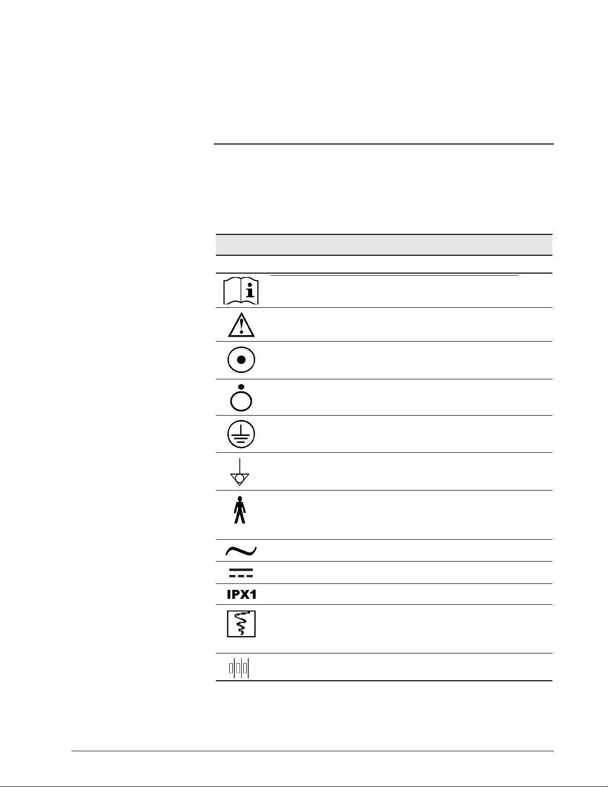
Chapter 3. Symbols
The following symbols appear on the Respironics V200 V entilator, accessories,
documentation, and packaging. Additional symbols pertaining to options and
accessories are included in the documentation for each option or accessory.
Refer to Chapter 13, “Options and Accessories”.
Symbol Description
Symbols
READ THE USER MANUAL OR ACCOMPANYING DOCUMENTS
ATTENTION
ON condition for part of the equipment. When pressed, the ventilator
will operate from the MAINS voltage if connected or from the backup
battery if the battery charge is within operating specifications.
OFF condition for part of the equipment
PROTECTIVE EARTH (ground)
POTENTIAL EQUALIZATION CONNECTOR used to connect the
equipment to an electrical installation earth busbar
TYPE B applied part, which indicates equipment that provides a
particular degree of protection against electric shock, particularly with
regards to allowable leakage current and of the protective earth
connection
SUITABLE FOR ALTERNATING CURRENT
DIRECT CURRENT
DRIP PROOF
Chart recorder ANALOG OUTPUT. Pin 12 signals an unsilenced high or
medium urgency alarm: 0 VDC= active alarm, 1.5 VDC = no alarm or
silenced alarm. (Voltage signal for flow and pressure reserved for futur e
use.)
DC BATTERY CONNECTION
Table 3-1: Symbols (Sheet 1 of 5)
REF 1057983 A Respironics V200 Ventilator Operator’s Manual 3-1
Chapter 3
Symbols
Symbols (Continued)
Symbol Description
DC BATTERY CONNECTION
HOT SURFACE warning
EUROPEAN CONFORMITY
REMOTE ALARM connection
RS-232 serial output
PARALLEL PORT printer connection
ALARM SILENCE (Silences alarm for two minutes)
BRIGHTNESS ADJUST
AUDIO ALARM VOLUME CONTROL
ACCEPT
ALARM RESET
100% OXYGEN
Located between the ALARM RESET and 100% O2 buttons, this
symbol indicates that the two keys (ALARM RESET AND 100% O
must be pressed simultaneously for approximately five seconds to enter
Diagnostic Mode
2)
Table 3-1: Symbols (Sheet 2 of 5)
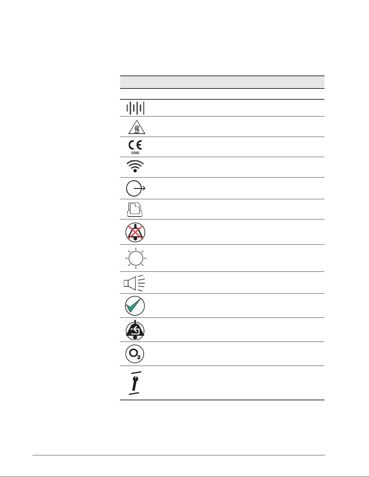
3-2 Respironics V200 Ventilator Operator’s Manual REF 1057983 A
Symbol Description
MANUAL BREATH
EXPIRATORY HOLD
SCREEN LOCK
(Symbol version of the front panel only) Illuminates yellow to indicate
backup battery IN USE (backup)
Chapter 3
Symbols
Symbols (Continued)
(Symbol version of the front panel only) llluminates yellow to indicate
backup battery CHARGING
(Symbol version of the front panel only) Flashes red to indicate that the
backup battery is LOW
(Symbol version of the front panel only) MAINS battery indicator
(Symbol version of the front panel only) EXTERNAL BATTERY is in use
DANGEROUS VOLTAGE—electrical shock hazard
The portion of the circuit breaker that must be pushed in to turn the
CIRCUIT BREAKER OFF
The portion of the circuit breaker that must be pushed in to turn the
CIRCUIT BREAKER ON
CANADIAN STANDARDS ASSOCIATION approval.
DATE OF MANUFACTURE
MANUF ACTURER
Table 3-1: Symbols (Sheet 3 of 5)
REF 1057983 A Respironics V200 Ventilator Operator’s Manual 3-3
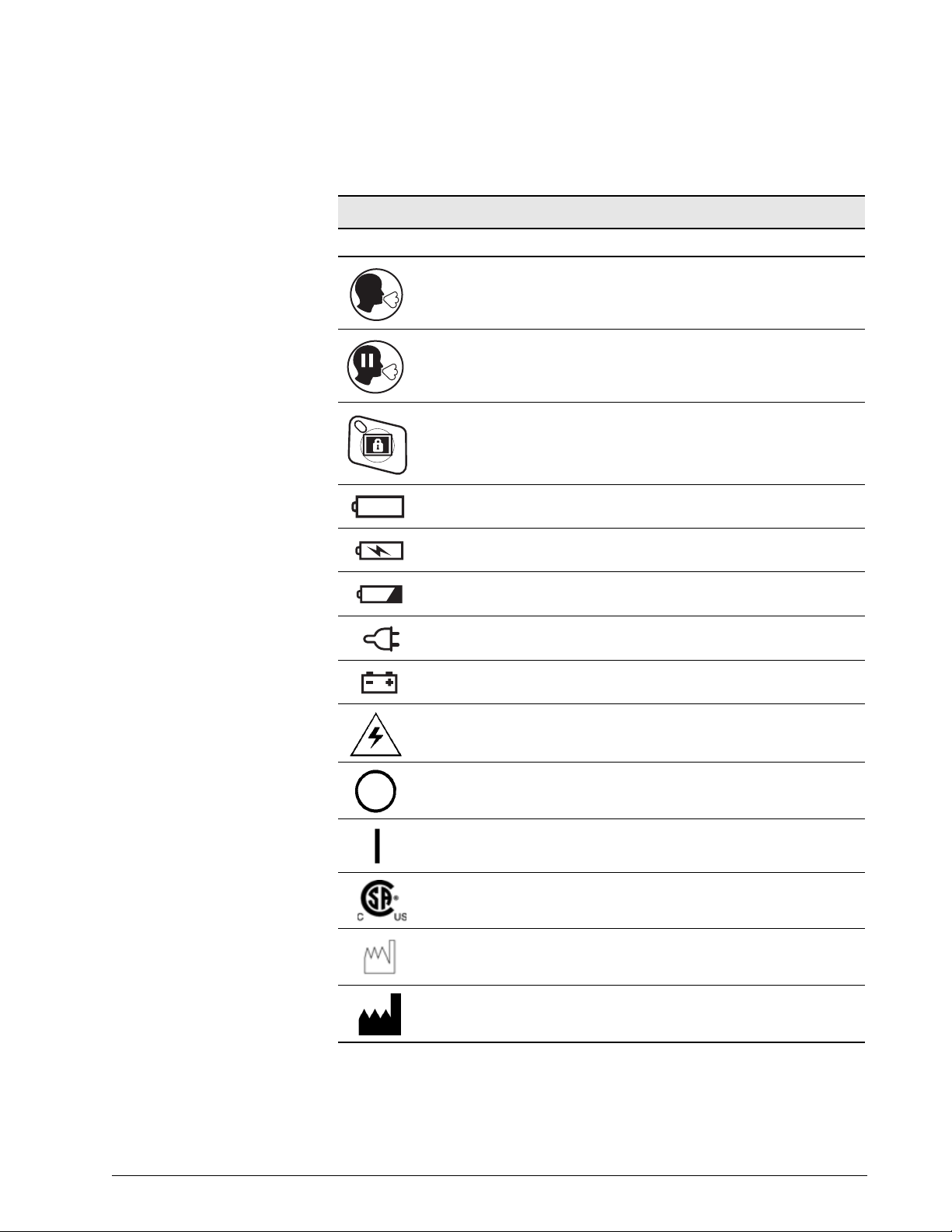
Chapter 3
Symbols
Symbol Description
The product must be disposed of in accordance with the WEEE
directive.
SEALED, NON-SPILLABLE LEAD ACID BATTERY. MUST BE
RECYCLED
Pb
SEALED, NON-SPILLABLE LEAD-ACID BATTERY. MUST BE
Pb
RECYCLED
RECYCLE
Symbols (Continued)
-20C
500-1060 hPa
THIS SIDE UP
AT LEAST TWO PEOPLE ARE REQUIRED TO LIFT THE VENTILATOR
TO AVOID POSSIBLE PERSONAL INJURY OR DAMAGE TO THE
EQUIPMENT.
KEEP DRY
LIMIT TEMPERATURE TO BETWEEN-20 AND 60 ºC (-4 AND 140 ºF)
+60C
FRAGILE
Table 3-1: Symbols (Sheet 4 of 5)
3-4 Respironics V200 Ventilator Operator’s Manual REF 1057983 A
Symbol Description
STORE AT 10%-95% RELATIVE HUMIDITY
%
10-95
Do not stack > 2 high
2
Chapter 3
Symbols
Symbols (Continued)
Table 3-1: Symbols (Sheet 5 of 5)
REF 1057983 A Respironics V200 Ventilator Operator’s Manual 3-5

Chapter 3
Symbols
(This page is intentionally blank.)
3-6 Respironics V200 Ventilator Operator’s Manual REF 1057983 A
Chapter 4. Getting Started
Unpacking The Respironics V200 Ventilator has been carefully packaged to assure safe
shipping. In addition, the packing container has been designed for easy
unpacking. Do not discard packing materials.
Before unpacking the ventilator, examine the shipping carton(s) for visible
damage. If the shipping carton(s) arrives damaged or if you suspect the
contents are damaged, contact the carrier for an inspection report. If any
damage is evident, we recommend that you photograph the carton(s) before
the shipment is unpacked. Report any damage to the shi pping container or
ventilator to your local authorized Respironics distributor and to the carrier.
Save all packing material after removing the ventilator. In the event that the
ventilator or backup battery needs to be repacked and reshipped, use the
original packing material or order replacement material from a Respironics
representative.
NOTE: The contents of the shipping carton may vary.
Top Foam Insert
Respironics V200 Ventilator
Center Foam Insert
Bottom Foam Insert
Figure 4-1: Unpacking/Repacking the Ventilator
WARNING: One person alone should not attempt to lift the ventilator or remove it from
the shipping carton or the cart. At least two people are required to avoid
possible personal injury or damage to the equipment.
REF 1057983 A Respironics V200 Ventilator Operator’s Manual 4-1

Chapter 4
Getting Started
NOTE: Medical electrical equipment needs special precautions regarding EMC
and needs to be installed and put into service according to the EMC
information provided in Chapter 12, “Technical Specifications”.
Unpacking Instructions
Refer to Figure 4-1.
• Tools Required: Box knife
1. Using a box knife, cut a slit in packaging tape on top of shipping
carton.
2. Remove accessories box and optional flex arm box (not shown).
3. Remove top foam insert from inside carton.
4. Roll the plastic shipping bag (not shown) off the ventilator.
5. Gently lift ventilator from the bag and carton.
6. Remove patient circuit package (not shown).
7. Store carton, foam insert, and plastic bag in safe place for possible
future use.
Inspection After unpacking the ventilator, inspect its cabinet exterior for damage,
including cracks and scratches or blemishes. Inspect the front panel for
scratches, chips, abrasions or other deformities.
CAUTION: Be sure to check all exterior parts of the ventilator. Problems found
during inspection should be corrected and/or reported to Respironics
before using the ventilator.
List of Parts and Accessories
Using the packing list that accompanies the ventilator, take an inventory of the
entire shipment before assembling the ventilator. In case of discrepancies,
immediately contact Respironics Customer Service at 1-800-345-6443.
The Esprit/V200 Ventilator Service Manual, P/N 580-1000-02, is available for
qualified personnel. It includes block diagrams, components parts lists,
descriptions, calibration instructions, and ot her information that will assist
appropriately qualified personnel to repair those parts of the equipment that
are designated by the manufacturer as repairable. For more information
contact Respironics Customer Service at 1-800-345-6443.
4-2 Respironics V200 Ventilator Operator’s Manual REF 1057983 A
 Loading...