

Philips UCB1500 Datasheet
UCB1500
PCI to AC97 bridge/host controller
Rev. 01 — 4 February 2000 Objective specification
1. General description
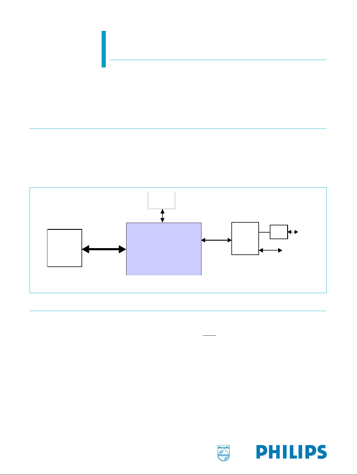
UCB1500 is a PCI-to-AC97 Bridge/Host Controller for modem or audio codecs
equipped with the AC-link interface. It integrates a PCI 2.2 compliant interface for
communication with the host PC, with built in support for PPMI (PCI Power
Management Interface) and wake-up. It also integrates an AC97 Rev. 2.1 compliant
host controller for connection to up to two AC-Link codecs, including analog modem
front ends such as the Philips UCB1510, and audio codecs.
Optional
EEPROM
c
c
PCI Interface
UCB1500
Host PC
Fig 1. Application with Philips UCB1510 analog modem front end
2. Features
■ 32-bit PCI 2.2 interface with bus master support
◆ Support up to two PCI functions with independent scatter/gather DMA
◆ PPMI and wake-up support via PME and V
◆ Download of subsystem IDs and auxiliary power consumption via optional
serial EEPROM
◆ 5 V tolerant interface for motherboard/PC add-on
■ AC97 rev 2.1 compliant host controller interface
◆ Supports up to two codecs
◆ Supports variable sample rate via the SLOTREQ protocol and valid tag bits
◆ Low latency GPIO data transfer
◆ Support modem wake-up on ring from D3cold
AC97
Interface
UCB1510
AUX
DAA
Phone
Line
GPIO
Philips Semiconductors
UCB1500
PCI to AC97 bridge/host controller
■ Advanced power management support
◆ PPMI (PCI Power Management Interface)
◆ Instantly available PC
◆ ACPI
3. Applications
■ PCI-AC97 bridge/host controller
■ PCI modem cards
■ Host based modems
4. Ordering information
Table 1: Ordering information
Type number Package
Name Description Version
UCB1500 LQFP80 plastic low profile quad flat package, 80 leads; body 12 × 12 × 1.4 mm SOT315-1
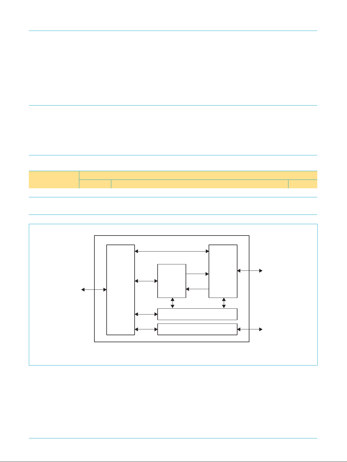
5. Block diagram
PCI
Interface
Fig 2. UCB1500 block diagram
PCI
Interface
DMA
Engine
Interrupt Control
EEPROM Interface
AC97
Controller
AC97
Interface
EEPROM
SC00177
9397 750 06854
Objective specification Rev. 01 — 4 February 2000 2 of 58
© Philips Electronics N.V. 2000. All rights reserved.

Philips Semiconductors
6. Pinning information
6.1 Pinning
UCB1500
PCI to AC97 bridge/host controller
V
GNT
REQ
AD31
AD30
V
AD29
AD28
AD27
AD26
V
AD25
AD24
CBE3
IDSEL
V
AD23
AD22
AD21
AD20
INTA
AD18
SS
V
AD17
BITCLK
AD16
V
CLKRUN
PCICLK
TEST
78 77 76 75 74 73 72 71 7080 79 69 68 67 66 65
1
DD
2
3
4
5
6
SS
7
8
9
10
11
DD
12
13
14
15
16
SS
17
18
19
20
23 24 25 26 27 28 29
DD
VSSV
AD19
EEPD
DD
SS
V
EEPCLK
UCB1500
30 3121 22
CBE2
FRAME
VAUX_AV
SYNC
SDATAOUT
32 33 34 35 36
SS
V
IRDY
TRDY
RST
VAUX
STOP
DEVSEL
AC97_RST
SDATAIN1
64
37
PERR
SERR
PME
SDATAIN0
63 62 61
38 39 40
DD
V
PAR
AD0
CBE1
DD
V
60
59
58
57
56
55
54
53
52
51
50
49
48
47
46
45
44
43
42
41
SS
V
SC00178
AD1
AD2
V
SS
AD3
AD4
AD5
AD6
V
DD
AD7
CBE0
AD8
AD9
V
SS
AD10
AD11
AD12
AD13
V
DD
AD14
AD15
Fig 3. Pin configuration
6.2 Pin description
Table 2: Pin description
Symbol Pin Type Description
PCI interface
PCICLK 80 I PCI system clock.
RST 68 I PCI system reset, V
REQ 3 T/S PCI bus request.
GNT 2 T/S PCI bus grant.
FRAME 29 S/T/S
9397 750 06854
Objective specification Rev. 01 — 4 February 2000 3 of 58
[1]
PCI FRAME, input during slave, output during master.
powered.
AUX
© Philips Electronics N.V. 2000. All rights reserved.

Philips Semiconductors
UCB1500
PCI to AC97 bridge/host controller
Table 2: Pin description
…continued
Symbol Pin Type Description
IRDY 30 S/T/S PCI IRDY, input during slave, output during master.
TRDY 31 S/T/S PCI TRDY, output during slave, input during master.
DEVSEL 33 S/T/S PCI DEVSEL, output during slave, input during master.
STOP 34 S/T/S PCI STOP, output during slave, input during master.
IDSEL 15 I PCI IDSEL signal.
AD[31:0] 4, 5, 7, 8, 9, 10, 12,
13, 17, 18, 19, 20,
23, 24, 25, 26,41,
42, 44, 45, 46, 47,
T/S PCI address/data.
slave mode: output only during data read phase.
master mode: output during address phase and data write phase.
49, 50, 52, 54, 55,
56, 57, 59, 60, 62
CBE[3:0] 14, 28, 39, 51 T/S PCI command/byte-enable, input during slave, output during master.
PAR 38 T/S PCI parity.
INTA 77 O/D
PME 63 O/D Open drain, V
[2]
PCI interrupt.
pins are V
powered PCI power management pin. SDA TAIN[1:0]
AUX
powered and can trigger PME.
AUX
SERR 36 O/D PCI system error
PERR 35 S/T/S PCI parity error
CLKRUN 78 S/T/S Primary PCI bus clock run. Used by the central resource to stop the PCI
clock or to slow it down
AC link controller interface
BITCLK 75 I Serial data clock; or input for secondary codecs.
SDATAIN[1:0] 65. 64 I Input from AC97/MC97 codecs. V
SDATAOUT 70 O Output to AC97/MC97 codecs. Driven to 0 at power-up or when
powered and can trigger PME.
AUX
RST
asserted.
SYNC 71 O AC97 sync. Driven to 0 at power-up or when
AC97_RST 66 O AC97 reset. Driven to 0 at power-up or when RST asserted. V
RST asserted.
AUX
powered.
Serial EEPROM interface
EEPCLK 73 O EEPROM clock.
EEPD 74 I/O EEPROM serial data port.
Power management; miscellaneous
_AV 69 I Auxiliary power available, V
V
AUX
powered.
AUX
TEST 79 I Test mode.
Power pins
V
DD
1, 11, 22, 27, 37,
S 3.3 V power pins.
43, 53, 61
V
SS
6, 16, 21, 32, 40,
S Ground pins.
48, 58, 72, 76
V
AUX
67 S Auxiliary power. If auxiliary power is not available or not necessary, this pin
must be connected to V
DD
.
[1] S/T/S: Sustained Tri-State is an active-LOW tri-state signal owned anddriven by one agent at a time. The agent that drives an S/T/S pin
LOW must drive it HIGH for at least one clock before letting it float. A new agent cannot start driving a S/T/S signal any sooner than one
clock after the previous owner tri-states it.
[2] O/D: Open Drain allows multiple devices to share as a wired OR.
9397 750 06854
Objective specification Rev. 01 — 4 February 2000 4 of 58
© Philips Electronics N.V. 2000. All rights reserved.

Philips Semiconductors
7. PCI configuration space
7.1 Overview
By default, UCB1500 supports a single modem function. Under control of BIOS or an
external serial EEPROM, UCB1500 can support a maximum of two PCI functions,
which are typically one modem plus one audio functions. To allow IHV to overwrite
parameters such as Device ID, Vendor ID, Subsystem Vendor ID, Subsystem ID,
Class Code and Power Management Capabilities, UCB1500 provides two schemes:
For each function, Device ID, Vendor ID, Subsystem Vendor ID, Subsystem ID,
•
Class Code and Power Management Capabilities are placed in a dedicated PCI
configuration read/write area accessible by the corresponding function. An enable
bit for Function 1 is placed in a dedicated read/write area accessible byFunction 0.
This allows IHVs to enable Function 1 and change the corresponding read-only
parameters of Functions 0 and 1 (if enabled) in the BIOS POST routine when
UCB1500 is used as a motherboard device.
In case UCB1500 is used as a PCI card which BIOS cannot control, the above
•
parameters, together with Function 1 enable, can be changed by the external
serial EEPROM.
UCB1500
PCI to AC97 bridge/host controller
The EEPROM data map is given in Table 3.
Table 3: EEPROM data map
Byte address Tag Description
00-01h signature 1516h = valid signature, otherwise disable autoloading.
02-03h control Bit 0: 1=enable function 1, 0=disable function 1
Bit 1: 1=enable function 0 auto-loading from address 04-9Dh
Bit 2: 1=enable function 0 auto-loading from address 0A-11h
Bit 3: 1=enable function 1 auto-loading from address 10-17h
Bit 4: 1=enable function 1 auto-loading from address 18-1Fh
Other bits: reserved and must be 0s.
04-05h sub_vendorID Function 0 subsystem vendor ID, PCI configuration space address 2C-2Dh.
06-07h subsystemID Function 0 subsystem ID, PCI configuration space address 2E-2Fh.
08-09h pmc Function 0 power management capabilities, PCI configuration space address 82h.
0A-0Bh vendorID Function 0 vendor ID, PCI configuration space address 00-01h.
0C-0Dh deviceID Function 0 device ID, PCI configuration space address 02-03h.
0Eh -- Reserved.
0F-11h classCode Function 0 Class Code, PCI configuration space address 09-0Bh.
12-13h sub_vendorID Function 1 subsystem vendor ID, PCI configuration space address 2C-2Dh.
14-15h subsystemID Function 1 subsystem ID, PCI configuration space address 2E-2Fh.
16-17h pmc Function 1 power management capabilities, PCI configuration space offset 82h.
18-19h vendorID Function 1 vendor ID, PCI configuration space address 00-01h.
1A-1Bh deviceID Function 1 device ID, PCI configuration space address 02-03h.
1Ch -- Reserved.
1D-1Fh classCode Function 1 Class Code, PCI configuration space address 09-0Bh.
9397 750 06854
Objective specification Rev. 01 — 4 February 2000 5 of 58
© Philips Electronics N.V. 2000. All rights reserved.

Philips Semiconductors
UCB1500
PCI to AC97 bridge/host controller
7.2 Configuration registers
7.2.1 Function 0 configuration registers
UCB1500 supports the PCI configuration cycle to control the UCB1500 access. It
sets up the PCI configuration bits and the UCB1500 IO port address. The following
table shows the supported PCI registers and their default values. Some of the
registers are programmable through the EEPROM interface (See EEPROM section
for details).
Remark: All registers are read/write, unless specified otherwise. Shaded registers
are read-only. A register with (S) means it is powered by V
sticky or otherwise stated, all read/write registers defaults to zero at PCI reset. All
reserved or unimplemented registers are hardwired to 0.
Table 4: Function 0 configuration registers
31-24 23-16 15-8 7-0 Address
Device ID = 3400
Modified by BIOS via writing to 42h or EEPROM auto
loading
Status = 0290 Command = 0000 04h
Class Code = 070300
Simple communication controller, generic modem.
Modified by BIOS via writing to 45h or EEPROM auto loading.
BIST = 00 Header Type
If multifunction,
header type = 80h,
otherwise 00h
I/O port Base Address [31:16]
Hardwired to 0000h
Reserved. 14h-2Bh
Subsystem ID = 3400
Modified by BIOS via writing to 6Eh or EEPROM auto
loading
Reserved 30h
Reserved
Reserved 38h
Reserved
Device ID Write = 3400 Vendor ID Write = 1131 40h
Class Code Write = 070300
Reserved EEPROM Status =00 48h
Reserved 4C-4Fh
Reserved
Reserved 54-67h
PMC Write = C801 Reserved 68h
Vendor ID = 1131
Modified by BIOS via writing to 40h or EEPROM auto
loading
Revision ID = 01 08h
Latency Timer = 00 Cache Line Size = 00 0Ch
I/O port Base Address[15:0] = 0001 10h
Subsystem Vendor ID = 1131
Modified by BIOS via writing to 6Ch or EEPROM auto
loading
Capability Pointer = 80 34h
Interrupt Pin = 01 Interrupt Line = 00 3Ch
Revision ID = 01 44h
Test Register = 00 50
and is sticky. Unless
AUX
00h
2Ch
9397 750 06854
Objective specification Rev. 01 — 4 February 2000 6 of 58
© Philips Electronics N.V. 2000. All rights reserved.

Philips Semiconductors
UCB1500
PCI to AC97 bridge/host controller
Table 4: Function 0 configuration registers
31-24 23-16 15-8 7-0 Address
Subsystem ID Write = 3400 Subsystem Vendor ID Write = 1131 6Ch
Reserved 70-7Fh
PMC =
4801 (V
C801 (V
Modified by BIOS via writing to 6Ah, or EEPROM
autoloading to PCI-PM1.1
Reserved PMCSR = 0000 (S) 84h
= 0, no autoload)
AUX_AV
= 1, no autoload)
AUX_AV
…continued
Next Item Per = 00 Capability ID = 01 80h
[01-00]: Vendor ID (read only): Programmable through EEPROM interface, or
register 40h. Default value = 1131h
[03-02]: Device ID (read only): Programmable through EEPROM interface, or
register 42h. Default value = 3400h
[05-04]: Command Register
Table 5: Command Register bit description
Bit Description
15-10 Reserved.
9(r) Fast Back-to-back Transactions
Always 0, fast back-to-back transactions is not supported.
8
7(r) Address/Data Stepping
6 Parity Error Response
5(r) VGA Snooping
4(r) Memory Write and Invalidate Command
3(r) Special Cycle Response
2 Bus Master Control
1(r) Memory Space Response
0 I/O Space Control
SERR enable
If set,
SERR driver is enabled; if 0, SERR is disabled.
Always 0, address/data stepping is not implemented.
When set, the device must take its normal action when a parity error is detected.
If this bit is 0, the devicemust ignore any parity errors that it detects and continue
normal operation.
Always 0, not implemented.
Always 0, UCB1500 does not generate memory write and invalidate command.
Always 0, UCB1500 ignores all special cycles.
PCI Master access enable; this bit must be enabled to activate UCB1500 DMA
register.
1 = enable.
Always 0, UCB1500 does not respond to memory space accesses.
UCB1500 control register I/O space access enable.
1 = enable.
9397 750 06854
Objective specification Rev. 01 — 4 February 2000 7 of 58
© Philips Electronics N.V. 2000. All rights reserved.

Philips Semiconductors
[07-06]: Status Register
Table 6: Status Register bit description
Bit Description
15
14
13 Received master abort
12 Received target abort
11(r) Target abort
10-9(r) Timing
8
7(r) Fast back-to-back capable
6(r) User Definable features
5(r) 66 MHz capable bit
4(r) Capabilities bit (read only)
3-0 Reserved.
UCB1500
PCI to AC97 bridge/host controller
PERR detected
Set to ‘1’ whenever parity error is detected. Write ‘1’ to clear.
SERR asserted
Set to ‘1’ if UCB1500 asserted
If set, UCB1500 has received master abort during its slaveoperation. Write ‘1’ to
clear.
If set, UCB1500 has received target abort during its master operation. Write `1'
to clear
Always ‘0’; UCB1500 never signals target abort.
Always 01b; wait state during slave access to UCB1500.
PERR reported
Not implemented, always 0.
Always ‘1’; NO wait state between PCI cycles.
Always ‘0’; device does not support user definable features.
Always ‘0’; device is 33MHz device only.
Always ‘1’; capabilities present.
SERR. Write ‘1' to clear.
[08]: Revision ID (read only): Current revision of chip = 1.
[0B-09]: Class Code Register (read only): Value = 070300h for simple
communication controller, generic modem. Programmable through EEPROM
interface or register 47-45h.
[0C]: Cache Line Size (read only): Always 0; no cache supported.
[0D]: Latency Timer
Table 7: Latency Timer register bit description
Bit Description
7-4 Latency Timer
Bits 7-4 of the latency timer, in units of PCI clocks * 16.
3-0(r) Latency Timer
These bits are read only and are always0000b, giving timer granularity of 16 PCI
clocks.
[0E]: Header Type (read only): If multifunction device, value is 80h otherwise 00h.
9397 750 06854
Objective specification Rev. 01 — 4 February 2000 8 of 58
© Philips Electronics N.V. 2000. All rights reserved.

Philips Semiconductors
[0F]: BIST (read only): Always 0; no built-in test capability.
[10]: I/O port base address
Table 8: I/O Port Base Address register bit description
Bit Description
31-16(r) I/O port Base address
15-4 I/O port Base address
3-1 Always 000b
0 Always 1b
[2C-2F] Subsystem ID/Subsystem Vendor ID (read only): Programmable through
EEPROM interface or through register 6e-6ch. Default Value = 3400h/1131h.
[34] Capability pointer (read only): 80h points to start offset of power management
registers.
[3C]: Interrupt Register
UCB1500
PCI to AC97 bridge/host controller
A[31:16] always 0.
A[15:4]; programmable address space for control registers.
Table 9: Interrupt Register bit description
Bit Description
15:8 Interrupt pin (read only)
Always 01h; interrupt pin connected to
7:0 Interrupt line
Interrupt line routing information.
INTA.
[40-43] Device ID Write / Vendor ID Write: This register contains a copy of the
Device ID and Vendor ID registers. Writing to this register will update the original
Device ID and Vendor ID registers (offset 0h - 3h).
[44h]: Revision ID: Same as offset 08h.
[45-47] Class code Write: This register contains a copy of the Class Code registers.
Writing to this register will update the original Class Code registers (offset 9h-Bh).
[48]: EEPROM status register /Misc
Table 10: EEPROM Status register bit description
Bit Description
0 EEPROM autoload status
If set, EEPROM autoload cycle is in progress.
9397 750 06854
Objective specification Rev. 01 — 4 February 2000 9 of 58
© Philips Electronics N.V. 2000. All rights reserved.

Philips Semiconductors
[50]: Test Register (For internal use only)
Table 11: Test Register bit description
Bit Description
0 Test Mode Enable
1 EEPROM Autoload enable
[6A-6B]: Power Management capabilities Write: This register contains a copy of
the Power Management capabilities register. Writing to this register will update the
original Power Management capabilities register (offset 82h-83h).
[6C-6F]: Subsystem-ID Write / Vendor ID Write: This register contains a copy of
the Subsystem-ID/Vendor ID register. Writing to this register will update the original
Subsystem-ID/Vendor ID registers (offset 2Ch-2Fh).
[80]: Capability Identifier (read only): This register is set to 01h to indicate power
management interface registers.
UCB1500
PCI to AC97 bridge/host controller
If set, chip operates under test mode. If ‘0’, chip operates normally.
If set, EEPROM autoload is disabled. If `0', EEPROM autoload sequence
operates as normal, depending on the EEPROM signature. This bit is for testing
only.
[81]: Next Item Pointer (read only): This field provides an offset into the function's
PCI Configuration Space pointing to the location of next item in the function's
capability list. This register is set to zero, signifying that there are no additional items
in the capability list.
9397 750 06854
Objective specification Rev. 01 — 4 February 2000 10 of 58
© Philips Electronics N.V. 2000. All rights reserved.

Philips Semiconductors
[82]: Power Management Capabilities (read only)
Table 12: Power Management Capabilities register bit description
Read only
Bit Description
15-11(r) PME support
10(r) D2 support
9(r) D1 support
8-6(r) Aux_Current
5(r) DSI
4(r) Reserved.
3(r) PME Clock
2:0(r) Version
UCB1500
PCI to AC97 bridge/host controller
This 5-bit field indicates the power states in which the function may assert
Value is set to 11001 b if V
D3cold and D0. If V
AUX_AV
= 1 to indicate PME can be asserted from
AUX_AV
= 0, this field is set to 01001b to indicate PME can be
asserted from D3hot and D0.
The entire setting can be overwritten by BIOS via writing to 6Ah, or an external
EEPROM. If V
= 0, bit 15 shall always be zero. If V
AUX_AV
= 1, bit 15 shall
AUX
reflect the setting of 6Ah, or that loaded from EEPROM.
This bit is set to ‘0’ to indicate that function does not support the D2 power
management state. This setting can be overwritten by BIOS via 6Ah, or with the
external EEPROM.
This bit is set to ‘0’ to indicate that function does not support the D1 power
management state. This setting can be overwritten by BIOS via 6Ah, or with the
external EEPROM.
These bits are set to ‘0’ for PCI-PM 1.0 compliance. For PCI-PM 1.1 compliance,
these bits are overwritten by BIOS via 6Ah, or loaded from an external EEPROM
to reflect the 3.3V
current requirement.
AUX
The Device Specific Initialization bit indicates whether special initialization of this
function is required (beyond the standard PCI configuration header) before the
generic class device driver is able to use it. This register is set to ‘0’ to indicate
that it does not require special initialization.
This bit is a ‘0’, indicating that the function does not rely on the presence of the
PCI clock for
PME operation.
This register is set to 001b, indicating that this function complies with Rev 1.0 of
PCI Power Management Interface Specification
the
. These bits can also be
overwritten by BIOS via 6Ah, or loaded from an external EEPROM to 010b for
compliance with PCI-PM 1.1.
PME.
9397 750 06854
Objective specification Rev. 01 — 4 February 2000 11 of 58
© Philips Electronics N.V. 2000. All rights reserved.

Philips Semiconductors
UCB1500
PCI to AC97 bridge/host controller
[84]: Power Management Control/Status: (V
powered: Only PME Status and
AUX
PME_EN are sticky.)
Table 13: Power Management Control/Status register bit description
Bit Description
15 PME Status - Sticky Bit
This bit is set when the function would normally assert the
independent of the state of the PME_EN bit. This bit is set when a power
management event occurs.
Writing a ‘1’ to this bit will clear it and cause the function to stop asserting a
(if enabled). Writing a ‘0’ has no effect.
14-13(r) Data scale
Not implemented.
12-9 Data select
This 4-bit field is used to select which data is to be reported through the Data
register and Data scale field. This function is not implemented in this chip.
8 PME_EN - Sticky Bit
A ‘1’ enables the function to assert
7-2(r) Reserved.
1-0 Power State
This 2-bit field is used both to determine the current power state of a function
and to set the function into a new power state. The definition of the field values is
given below.
00b - D0
01b - D1
10b - D2
11b - D3hot
If software writes D1 or D2 and the corresponding bit 10 or 9 or register 82
indicates it is not supported, the state change is discarded.
PME. When ‘0’, PME assertion is disabled.
PME signal
PME
[86-87]: Reserved.
9397 750 06854
Objective specification Rev. 01 — 4 February 2000 12 of 58
© Philips Electronics N.V. 2000. All rights reserved.

Philips Semiconductors
UCB1500
PCI to AC97 bridge/host controller
7.2.2 Function 1 Configuration Registers
Table 14: Function 1 configuration registers
31-24 23-16 15-8 7-0 Address
Device ID = 3401
Modified by BIOS via writing to 42h or
EEPROM auto loading
Status = 0290 Command = 0000 04h
Class Code = 040100
Multimedia Audio Device.
Modified by BIOS via writing to 45h or EEPROM auto loading.
BIST = 00 Header Type = 00 Latency Timer = 00 Cache Line Size = 00 0Ch
I/O port Base Address [31:16]
Hardwired to 0000h
Reserved. 14h-2Bh
Subsystem ID = 3401
Modified by BIOS via writing to 6Eh or
EEPROM auto loading
Reserved 30h
Reserved 38h
Reserved
Device ID Write = 3401 Vendor ID Write = 1131 40h
Class Code Write = 040100
Reserved EEPROM Status =00 48h
Reserved 4C-4Fh
Reserved Test Register* = 00 50
Reserved 54-67h
PMC Write = 0401 Reserved 68h
Subsystem ID Write = 3401 Subsystem Vendor ID Write = 1131 6Ch
Reserved 70-7fh
PMC = 0401
Modified by BIOS via writing to 6Ah, or
EEPROM autoloading to PCI-PM1.1
Reserved PMCSR = 0000 (S) 84h
Vendor ID = 1131
Modified by BIOS via writing to 40h or
EEPROM auto loading
Revision ID = 01 08h
I/O port Base Address[15:0] = 0001 10h
Subsystem Vendor ID = 1131
Modified by BIOS via writing to 6Ch or
EEPROM auto loading
Capability Pointer = 80 34h
Interrupt Pin = 01 Interrupt Line = 00 3Ch
Revision ID = 01 44h
Next Item Ptr = 00 Capability ID = 01 80h
00h
2Ch
[01-00]: Vendor ID (read only): Programmable through EEPROM interface, or
register 40h. Default value = 1131h
[03-02]: Device ID (read only): Programmable through EEPROM interface, or
register 42h. Default value = 3401h
9397 750 06854
Objective specification Rev. 01 — 4 February 2000 13 of 58
© Philips Electronics N.V. 2000. All rights reserved.

Philips Semiconductors
[05-04]: Command Register
Table 15: Command Register bit description
Bit Description
15-10 Reserved.
9(r) Fast Back-to-back Transactions
8
7(r) Address/Data Stepping
6 Parity Error Response
5(r) VGA Snooping
4(r) Memory Write and Invalidate Command
3(r) Special Cycle Response
2 Bus Master Control
1(r) Memory Space Response
0 I/O Space Control
UCB1500
PCI to AC97 bridge/host controller
Always 0, fast back-to-back transactions is not supported.
SERR enable
If set,
SERR driver is enabled; if 0, SERR is disabled.
Always 0, address/data stepping is not implemented.
When set, the device must take its normal action when a parity error is detected.
If this bit is 0, the devicemust ignore any parity errors that it detects and continue
normal operation.
Always 0, not implemented.
Always 0, UCB1500 does not generate memory write and invalidate command.
Always 0, UCB1500 ignores all special cycles.
PCI Master access enable; this bit must be enabled to activate UCB1500 DMA
register.
1 = enable.
Always 0, UCB1500 does not respond to memory space accesses.
UCB1500 control register I/O space access enable.
1 = enable.
9397 750 06854
Objective specification Rev. 01 — 4 February 2000 14 of 58
© Philips Electronics N.V. 2000. All rights reserved.

Philips Semiconductors
[07-06]: Status Register
Table 16: Status Register bit description
Bit Description
15
14
13 Received master abort
12 Received target abort
11(r) Target abort
10-9(r) Timing
8
7(r) Fast back-to-back capable
6(r) User Definable features
5(r) 66 MHz capable bit
4(r) Capabilities bit (read only)
3-0 Reserved.
UCB1500
PCI to AC97 bridge/host controller
PERR detected
Set to ‘1’ whenever parity error is detected. Write ‘1’ to clear.
SERR asserted
Set to ‘1’ if UCB1500 asserted
If set, UCB1500 has received master abort during its slaveoperation. Write ‘1’ to
clear.
If set, UCB1500 has received target abort during its master operation. Write `1'
to clear
Always ‘0’; UCB1500 never signals target abort.
Always 01b; wait state during slave access to UCB1500.
PERR reported
Not implemented, always 0.
Always ‘1’; NO wait state between PCI cycles.
Always ‘0’; device does not support user definable features.
Always ‘0’; device is 33MHz device only.
Always ‘1’; capabilities present.
SERR. Write ‘1' to clear.
[08]: Revision ID (read only): Current revision of chip = 1.
[0B-09]: Class Code Register (read only): Value = 040100h for multimedia device,
audio. Programmable through EEPROM interface or register 47-45h.
[0C]: Cache Line Size (read only): Always 0; no cache supported.
[0D]: Latency Timer
Table 17: Latency Timer register bit description
Bit Description
7-4 Latency Timer
Bits 7-4 of the latency timer, in units of PCI clocks * 16.
3-0(r) Latency Timer
Bits 3-0 of the latency timer. These bits are read only and are always 0000b,
giving timer granularity of 16 PCI clocks.
[0E]: Header Type (read only): Always 0.
9397 750 06854
Objective specification Rev. 01 — 4 February 2000 15 of 58
© Philips Electronics N.V. 2000. All rights reserved.

Philips Semiconductors
[0F]: BIST (read only): Always 0; no built-in test capability.
[10]: I/O port base address
Table 18: I/O Port Base Address register bit description
Bit Description
31-16(r) I/O port Base address
15-4 I/O port Base address
3-1 Always 000b
0 Always 1b
[2C-2F] Subsystem ID/Subsystem Vendor ID (read only): Programmable through
EEPROM interface or through register 6E-6Ch. Default Value = 3401h / 1131h.
[34] Capability pointer (read only): 80h points to start offset of power management
registers.
[3C]: Interrupt Register
UCB1500
PCI to AC97 bridge/host controller
A[31:16] always 0.
A[15:4]; programmable address space for control registers.
Table 19: Interrupt Register register bit description
Bit Description
15:8 Interrupt pin (read only)
Always 01h interrupt pin connected to
7:0 Interrupt line
Interrupt line routing information.
INTA.
[40-43] Device ID Write / Vendor ID Write: This register contains a copy of the
Device ID and Vendor ID registers. Writing to this register will update the original
Device ID and Vendor ID registers (offset 0h-3h).
[44h]: Revision ID: Same as offset 08.
[45-47] Class code Write: This register contains a copy of the Class Code registers.
Writing to this register will update the original Class Code registers (offset 9h-Bh).
[48]: EEPROM status register /Misc
Table 20: EEPROM Status Register / Misc. register bit description
Bit Description
0 EEPROM autoload status
If set, EEPROM autoload cycle is in progress.
9397 750 06854
Objective specification Rev. 01 — 4 February 2000 16 of 58
© Philips Electronics N.V. 2000. All rights reserved.

Philips Semiconductors
[50]: Test Register (For internal use only)
Table 21: Test Register register bit description
Bit Description
0 Test Mode Enable
1 EEPROM Autoload Enable
[6A-6B]: Power Management capabilities Write: This register contains a copy of
the Power Management capabilities register. Writing to this register will update the
original Power Management capabilities register (offset 82h-83h).
[6C-6F]: Subsystem-ID Write / Vendor ID Write: This register contains a copy of
the Subsystem-ID/Vendor ID register. Writing to this register will update the original
Subsystem-ID/Vendor ID registers (offset 2Ch-2Fh).
[80]:Capability Identifier (read only): This register is set to 01h to indicate power
management interface registers.
UCB1500
PCI to AC97 bridge/host controller
If set, chip operates under test mode. If ‘0’, chip operates normally.
If set, EEPROM autoload is disabled. If ‘0’, EEPROM autoload sequence
operates as normal, depending on the EEPROM signature. This bit is for testing
only.
[81]: Next Item Pointer (read only): This field provides an offset into the function's
PCI Configuration Space pointing to the location of next item in the function's
capability list. This register is set to zero, signifying that there are no additional items
in the capability list.
9397 750 06854
Objective specification Rev. 01 — 4 February 2000 17 of 58
© Philips Electronics N.V. 2000. All rights reserved.

Philips Semiconductors
[82]: Power Management Capabilities (read only)
Table 22: Power Management Capabilities register bit description
Read only
Bit Description
15-11(r) PME support
10(r) D2 support
9(r) D1 support
8-6(r) Aux_Current
5(r) DSI
4(r) Reserved.
3(r) PME Clock
2:0(r) Version
UCB1500
PCI to AC97 bridge/host controller
This 5-bit field indicates the power states in which the function may assert
Value is set to 00000b to indicate no
The entire setting can be overwritten by BIOS via writing to 6Ah, or an external
EEPROM. If V
reflect the setting of 6Ah, or that loaded from EEPROM.
This bit is set to ‘1’ to indicate that function supports the D2 power management
state. This setting can be overwritten by BIOS via 6Ah, or with the external
EEPROM.
This bit is set to ‘0’ to indicate that function does not support the D1 power
management state. This setting can be overwritten by BIOS via 6Ah, or with the
external EEPROM.
These bits are set to ‘0’ for PCI-PM 1.0 compliance. For PCI-PM 1.1 compliance,
these bits are overwritten by BIOS via 6Ah, or loaded from an external EEPROM
to reflect the 3.3V
The Device Specific Initialization bit indicates whether special initialization of this
function is required (beyond the standard PCI configuration header) before the
generic class device driver is able to use it. This register is set to ‘0’ to indicate
that it does not require special initialization.
This bit is a ‘0’, indicating that the function does not rely on the presence of the
PCI clock for
This register is set to 001b, indicating that this function complies with Rev 1.0 of
PCI Power Management Interface Specification
the
overwritten by BIOS via 6Ah, or loaded from an external EEPROM to 010b for
compliance with PCI-PM 1.1.
PME operation.
= 0, bit 15 shall always be zero. If V
AUX_AV
current requirement.
AUX
PME can be asserted.
AUX
. These bits can also be
= 1, bit 15 shall
PME.
9397 750 06854
Objective specification Rev. 01 — 4 February 2000 18 of 58
© Philips Electronics N.V. 2000. All rights reserved.
 Loading...