


INTEGRATED CIRCUITS
DATA SH EET
UBA2000T
Electronic TL-lamp starter
Product specification
File under Integrated Circuits, IC11
1996 Jan 03

Philips Semiconductors Product specification
Electronic TL-lamp starter UBA2000T
FEATURES
• Electronic starter, fully compatible with conventional
glow-switch starters
• Reliable and instant ignition
• Accurate defined preheat time derived from the mains
frequency
• Increased starter life since no mechanical parts are
used
• No radio-interference (according to
• Automatic reset after interruption of supply voltage
• Large operating temperature range: −40 to +85 °C
• Maximum current protection of the preheat current
• Ignition shut-off at end of lamp life; no overheating of
load.
ORDERING INFORMATION
TYPE NUMBER
NAME DESCRIPTION VERSION
UBA2000T SO8 plastic small outline package; 8 leads; body width 3.9 mm SOT96-1
“IEC926 10.5”
)
GENERAL DESCRIPTION
The UBA2000T is an integrated circuit for electronic
TL-lamp starters and is fully compatible with conventional
glow switch starters. The circuit controls the preheating
and ignition of the lamp. The preheat time is well defined
without spread, since it is derived from the mains
frequency. When the lamp fails, ignition is shut-off after 7
ignition attempts. The circuit has an automatic reset when
the supply voltage is interrupted.
PACKAGE
1996 Jan 03 2
Philips Semiconductors Product specification
Electronic TL-lamp starter UBA2000T
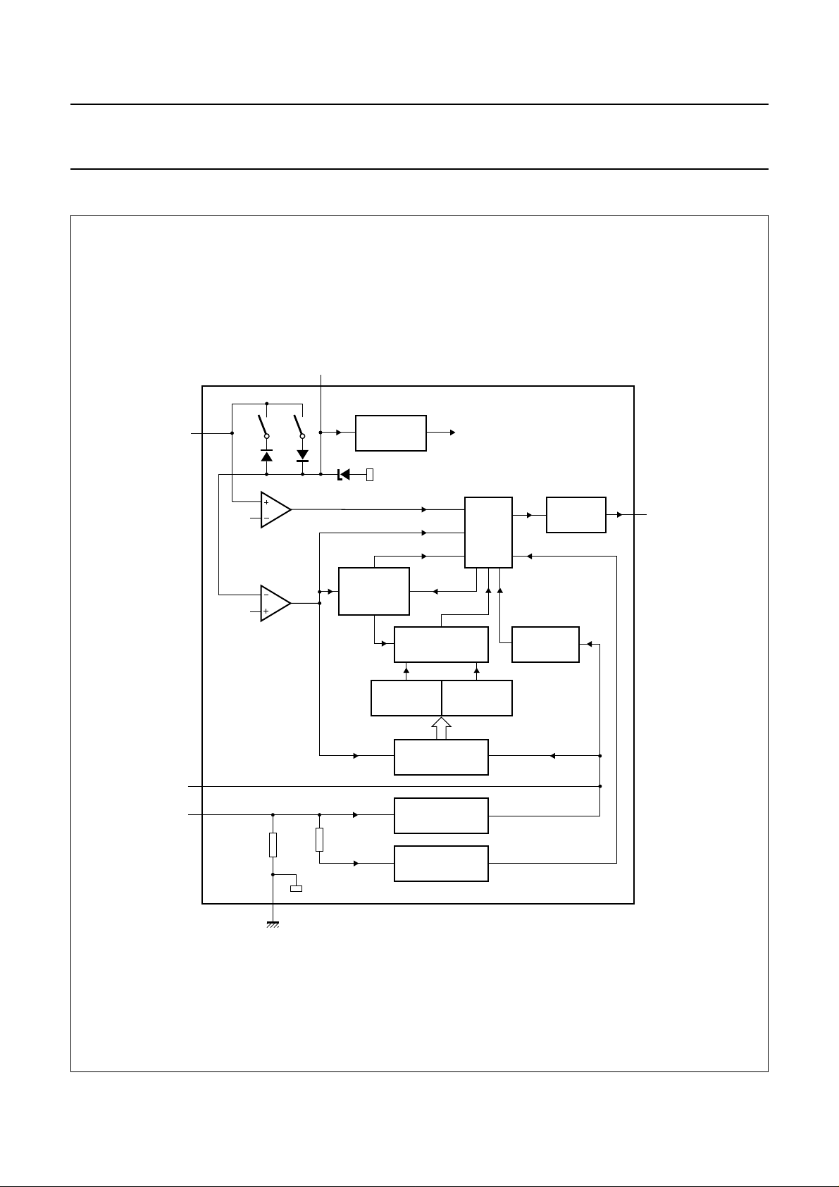
BLOCK DIAGRAM
handbook, full pagewidth
V
TEST
sense
V
CC
6
4
V
in
IC-SUPPLY
V
supply
UBA2000T
V
CC(rst)
8
1
V
ign
VOLTAGE
DETECTORS
R
sense
THS
RES
OF STARTS
COUNTER
1 kΩ
NUMBER
TIME
SELECT
DECODER 1 DECODER 2
COUNTER
CURRENT
DETECTOR
CURRENT
PROTECTION
LATCH
OUTPUT
DRIVER
EDGE
DETECTOR
3
V
out
2
GND
Fig.1 Block diagram.
1996 Jan 03 3
MGE002
Philips Semiconductors Product specification
Electronic TL-lamp starter UBA2000T
PINNING
SYMBOL PIN DESCRIPTION
V
sense
1 sense voltage
GND 2 ground (0 V)
V
out
V
in
3 output voltage
4 input voltage
n.c. 5 not connected
V
CC
6 supply voltage
n.c. 7 not connected
TEST 8 test pin
handbook, halfpage
V
sense
V
out
V
in
1
2
UBA2000T
3
4
MGE001
Fig.2 Pin configuration.
TEST
8
n.c.GND
7
V
6
CC
n.c.
5
FUNCTIONAL DESCRIPTION
The UBA2000T is an Integrated Circuit that performs all
functions necessary to ignite a TL-lamp. The circuit is
connected to the lamp circuit according to Figs. 7 or 8.
The mains voltage is rectified and divided over resistors
R1 and R2 to a lower level. When the mains power is
switched on, the buffer capacitor C1 is charged through
the resistive divider and internal switch S1. As long as the
supply voltage at the buffer capacitor (VCC, see
“Characteristics”) is below the reset level (V
CC(rst)
),
the UBA2000T initializes its internal circuitry.
When V
has reached the start level (V
CC
peak value of Vin>V
(indicating that the mains supply is
ign
CC(sl)
) and the
near its peak value), the external switching device TH1 will
be turned on. This results in a current through the
electrodes of the TL-lamp, the switching device and an
integrated sense resistor. Because the current starts to
flow when the mains voltage is near its peak value,
transient currents are limited.
handbook, full pagewidth
V
CC(sl)
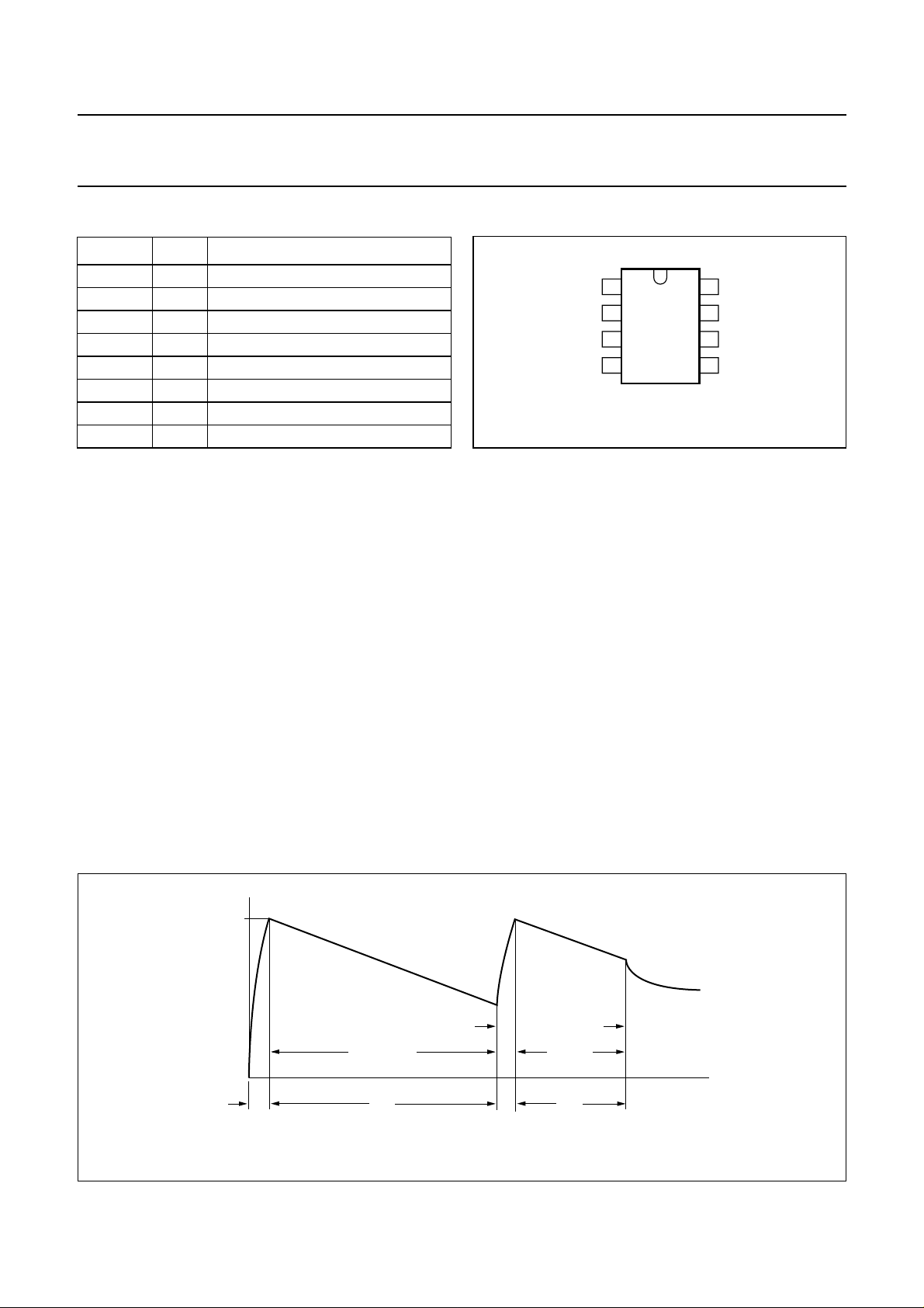
When the switching device is turned on, the circuit draws
its supply current from buffer capacitor C1. A typical wave
shape of the voltage at pin 6 (V
) is given in Fig.3. During
CC
the preheat periods the buffer capacitor is discharged.
The rectified current through the sense resistor is detected
and the output signal of the detector is used as a clock
signal for the counter. The preheat time is defined to 1.52 s
(at 50 Hz mains supply) using this counter. The preheat
time is very accurate, since it only depends on the
frequency of the mains supply.
After preheating, the switching device is turned off when
the current through the internal sense resistor equals at
least 285 mA. As a result of the current interruption and the
presence of an inductive load, a voltage peak is generated
that will normally ignite the TL-lamp. After ignition, the
lamp voltage is lower than the mains voltage. An ignited
TL-lamp prevents the voltage at pin 6 (VCC) to exceed start
level. In Fig.3 the TL-lamp is ignited after two ignition
attempts.
MGE006
V
CC
first
ignition
first preheat
t
ini
t
prf
Fig.3 Typical wave shape of supply voltage.
1996 Jan 03 4
second
ignition
second
preheat
t
prn
time
Philips Semiconductors Product specification
Electronic TL-lamp starter UBA2000T
During preheating, the integrated circuit draws its supply
current from the buffer capacitor. As a result, the voltage
over the buffer capacitor decreases. When the ignition has
failed after the ignition pulse, the voltage on the buffer
capacitor increases to start level and the external
switching device will be turned on again. This time the
preheat time is reduced to 0.64 seconds because the lamp
electrodes are still warm. An internal counter limits the
number of ignitions attempts to 7. This prevents the lamp
from flickering at end of lamp life.
The UBA2000T has an integrated current protection.
When the current through the sense resistor exceeds the
protection level (I
), the switching device is turned off
prot
and the circuit will enter a standby state. Switching the
mains voltage off and on again will reset the circuit.
The flow chart of the starting process is given in Fig.5.
In the following subsections the several blocks of the block
diagram are described in more detail.
IC supply
When the mains power is switched on, the buffer capacitor
is charged and the internal current source is started.
The internal voltage is stabilized, making it independent of
the voltage at the buffer capacitor. An internal zener diode
limits the voltage at pin 6 (V
) to start level (V
CC
CC(sl)
).
This time depends on the value of C1, the IC current and
the source resistance at pin V
(R1//R2). When the mains
in
voltage is near its peak value, the switching device is
actually turned on. When the voltage decreases to a value
indicating that the mains supply is interrupted, the starter
is ready to start preheating and igniting the TL-lamp at the
moment the mains supply returns.
Latch
The internal state of the latch represents the state of the
switching device. The setting of the latch depends on the
outputs of the voltage detectors, the number of starts
counter and the standby state. Resetting the latch is
controlled by the timer, the current detector and the current
protection circuit.
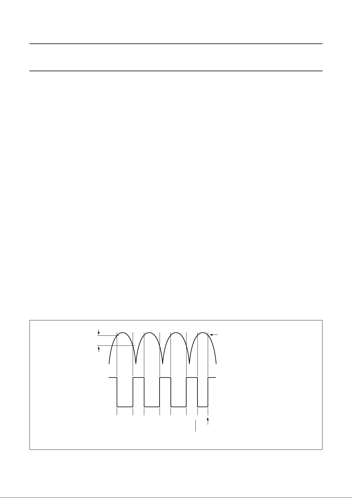
Current detector
The current detector detects when the switching device
must be turned off. The current detector also generates the
clock pulses to activate the counter (see Fig.4). For proper
functioning, the preheat current should be within the range
indicated by I
. By including an hysteresis, unwanted
pr
current peaks on the preheat current have no effect on the
counter. Because the current detector has a low-pass
transfer function, it is not influenced by spikes. This
circuitry eliminates the effect of spikes on the preheat time.
Voltage detectors
The voltage detectors measure the voltage on the buffer
capacitor and activate the switching device when the start
value (V
capacitor is the initial time (t
handbook, full pagewidth
) is reached. The time required to charge the
CC(sl)
, see also Fig.3).
ini
hysteresis
MGE007
clock generation during preheat
Fig.4 Current detection.
Edge detector
The edge detector ensures that the switching device will
be turned off when the rectified preheat current is on the
negative-going edge.
I
level
so
current through
sense resistor
clock signal
(fed to counter)
switch off level at end of preheat
1996 Jan 03 5
 Loading...