

Philips TEA5759HL, TEA5757HL Datasheet

INTEGRATED CIRCUITS
DATA SH EET
TEA5757HL; TEA5759HL
Self Tuned Radio (STR)
Product specification
File under Integrated Circuits, IC01
2000 Feb 02

Philips Semiconductors Product specification
Self Tuned Radio (STR) TEA5757HL; TEA5759HL
FEATURES
• The tuningsystem has an optimized IC partitioning both
from application (omitting interferences) and flexibility
(removable front panel option) point of view: the tuning
synthesizer is on-chip with the radio
• Thetuning quality issuperior and requiresno IF-counter
for stop-detection; it is insensitive to ceramic filter
tolerances
• In combination with the microcontroller, fast, low-power
operation of preset mode, manual-search, auto-search
and auto-store are possible
• Thelocal (internal) controller functionfacilitatesreduced
and simplified microcontroller software
• The high integration level (radio and tuning synthesizer
on one chip) means fewer external components with
regard to the communication between the radio and the
microcontroller (90% less components compared to the
digital tuning application of a radio IC with external PLL
tuning function) and a simple and small Printed-Circuit
Board (PCB)
• Therewill be no applicationconsiderationsfor the tuning
system, with regards to quality and high integration
level, since there will be no external 110 MHz buffers,
loop filter or false lock elimination
• The inherent FUZZY LOGIC behaviour of the Self
Tuned Radio (STR), which mimics hand tuning and
yields a potentially fast yet reliable tuning operation
• The level of the incoming signal at which the radio must
lock is software programmable
• Two programmable ports
• FM-on/off port to control an external FM front-end
• High selectivity with distributed IF gain
• Soft mute
• Signal dependent stereo-blend
• High impedance MOSFET input on AM
• Wide supply voltage range of 2.5 to 12 V
• Low current consumption 18 mA at AM and FM
(including tuning synthesizer)
• High input sensitivity
• Low output distortion
• Due to the new tuning concept, the tuning is
independent of the channel spacing.
GENERAL DESCRIPTION
The TEA5757HL; TEA5759HL is a 48-pin integrated
AM/FM stereo radio circuit including a novel tuning
concept. The radio part is based on the TEA5712.
The TEA5757HL is used in FM-standards in which the
local oscillator frequency is above the radio frequency
(e.g. european and american standards).
The TEA5759HL is the version in which the oscillator
frequency is below the radio frequency (e.g. Japanese
standard).
Thenew tuning conceptcombinesthe advantages ofhand
tuning with electronic facilities and features. User
‘intelligence’ is incorporated into the tuning algorithm and
animprovementofthe analog signal processing isusedfor
the AFC function.
ORDERING INFORMATION
TYPE
NUMBER
TEA5757HL LQFP48 plastic low profile quad flat package; 48 leads; body 7 × 7 × 1.4 mm SOT313-2
TEA5759HL LQFP48 plastic low profile quad flat package; 48 leads; body 7 × 7 × 1.4 mm SOT313-2
2000 Feb 02 2
NAME DESCRIPTION VERSION
PACKAGE
Philips Semiconductors Product specification
Self Tuned Radio (STR) TEA5757HL; TEA5759HL
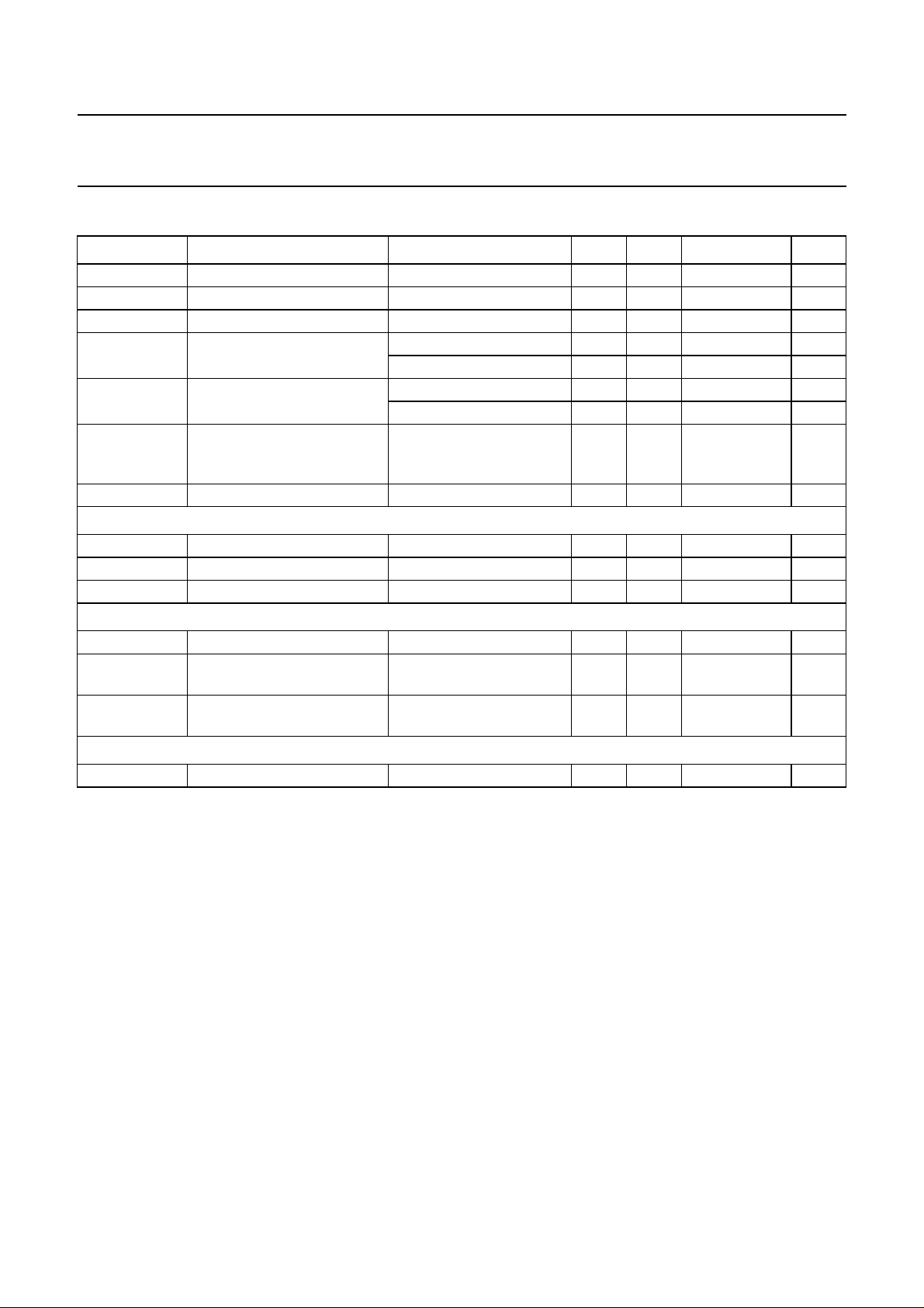
QUICK REFERENCE DATA
SYMBOL PARAMETER CONDITIONS MIN. TYP. MAX. UNIT
V
CC1
V
CC2
V
tune
I
CC1
I
DD
I
CC2
T
amb
AM performance; note 1
V
11
V
i1
THD total harmonic distortion V
FM performance; note 2
V
11
V
i5
THD total harmonic distortion IF filter
MPX performance; note 3
α
cs
supply voltage 2.5 − 12 V
supply voltage for tuning −−12 V
tuning voltage 0.7 − V
− 0.75 V
CC2
supply current AM mode 12 15 18 mA
FM mode 13 16 19 mA
supply current AM mode 2.8 3.3 3.7 mA
FM mode 2.4 2.7 3.0 mA
supply current for tuning in
−−800 µA
preset mode
(band-end to band-end)
ambient temperature −15 − +60 °C
AF output voltage Vi1= 5 mV 36 45 70 mV
RF sensitivity input voltage (S+N)/N = 26 dB 40 55 70 µV
=1mV − 0.8 2.0 %
i1
AF output voltage Vi5= 1 mV 40 48 57 mV
RF sensitivity input voltage V11at −3 dB; V11is 0 dB
0.4 1.2 3.8 µV
at Vi5=1mV
− 0.3 0.8 %
SFE10.7MS3A20K-A
channel separation 26 30 − dB
Notes
1. V
CC1
=3V; V
CC2
= 12 V; V
=3V; fi= 1 MHz; m = 0.3; fm= 1 kHz; measured in Fig.11 with S1 in position A; S2
DDD
in position B; unless otherwise specified.
2. V
CC1
=3V; V
CC2
= 12 V; V
=3V; fi= 100 MHz; ∆fm= 22.5 kHz; fm= 1 kHz; measured in Fig.11 with S2 in
DDD
position A; S3 in position A and S5 in position A; unless otherwise specified.
3. V
CC1
=3V;V
CC2
=12V;V
DDD
=3V;V
i3(L + R)
= 155 mV; V
= 15.5 mV; fi= 1 kHz; measured in Fig.11 with S2 in
pilot
position B; S3 in position B; unless otherwise specified.
2000 Feb 02 3
This text is here in white to force landscape pages to be rotated correctly when browsing through the pdf in the Acrobat reader.This text is here in
_white to force landscape pages to be rotated correctly when browsing through the pdf in the Acrobat reader.This text is here inThis text is here in
white to force landscape pages to be rotated correctly when browsing through the pdf in the Acrobat reader. white to force landscape pages to be ...
2000 Feb 02 4
FM-IFI1 FM-IFI2
FM-IFO1FM-MIXERFMOSC/COUNTI
FM
IF1
STATUS
REGISTER
SEQUENTIAL
CIRCUIT
AM
IF
AGC
up
down
level
FM
IF2
AM/FM
INDICATOR
IN-LOCK
DETECTOR
CHARGE
PUMP
hard mute
DETECTOR
IFGND FSIFMDEM
FM
DETECTOR
AFC
AM
191843 40 363836
22
TEA5757HL;
TEA5759HL
19 kHz
38 kHz
stereo
level
CONVERTER
PILOT
DETECTOR
PLL
DECODER
stereo
MATRIX
mono
SDS
MUTE
V/I
17
26
13
10
15
16
14
20
21
34
FM-RFI
RFGND2
DATA
BUS-CLOCK
WRITE-ENABLE
V
STAB(A)
V
STAB(B)
V
CC1
V
DDD
RIPPLE
FM-ON/OFF
XTAL
DGND
AM-RFI
FM-RFO
47
46
30
29
31
41
37
8
25
1
42
27
28
33
P1
32
P0
2
FM
FRONT-END
STABILIZER
PRESCALER
MULTIPLEXER
CRYSTAL
OSCILLATOR
AM
FRONT-END
OSCILLATOR
TUNER
SWITCH
OSCILLATOR
FM
SHIFT REGISTER
LAST-STATION
MEMORY
PROGRAMMABLE
COUNTER
WINDOW
DETECTOR
AM
FM
MIXER
AM
MIXER
FM
AM
PILFIL
MO/ST
LFI
VCO
AFLO
AFRO
MUTE
AFC
AFC
AFC
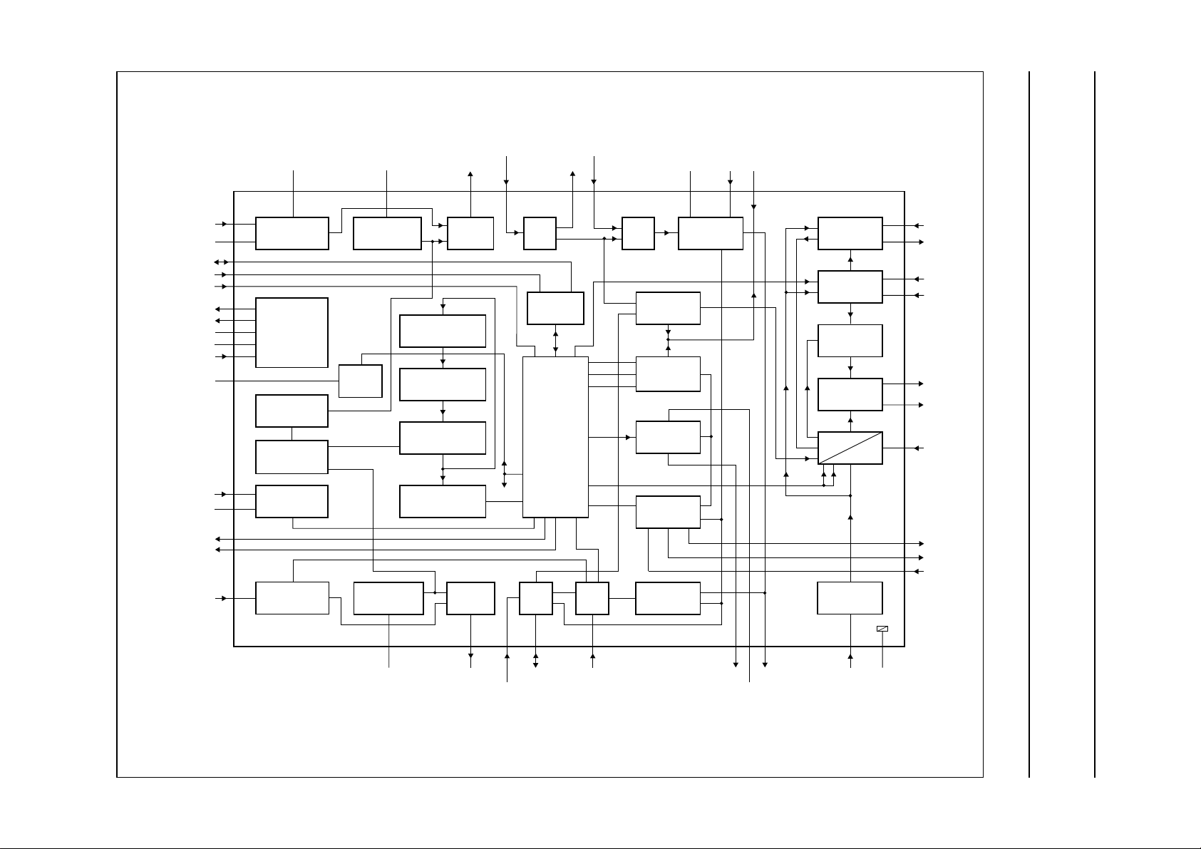
BLOCK DIAGRAM
Philips Semiconductors Product specification
Self Tuned Radio (STR) TEA5757HL; TEA5759HL
(n)
(p)
7
AM-MIXERAMOSC
44 45
AM-IFI1
39
AM-IFI/O2
AGC
48
TUNE
923
AFO
V
CC2
11
MPXI
12
4
RFGND1
MHB606
Fig.1 Block diagram.
handbook, full pagewidth

Philips Semiconductors Product specification
Self Tuned Radio (STR) TEA5757HL; TEA5759HL
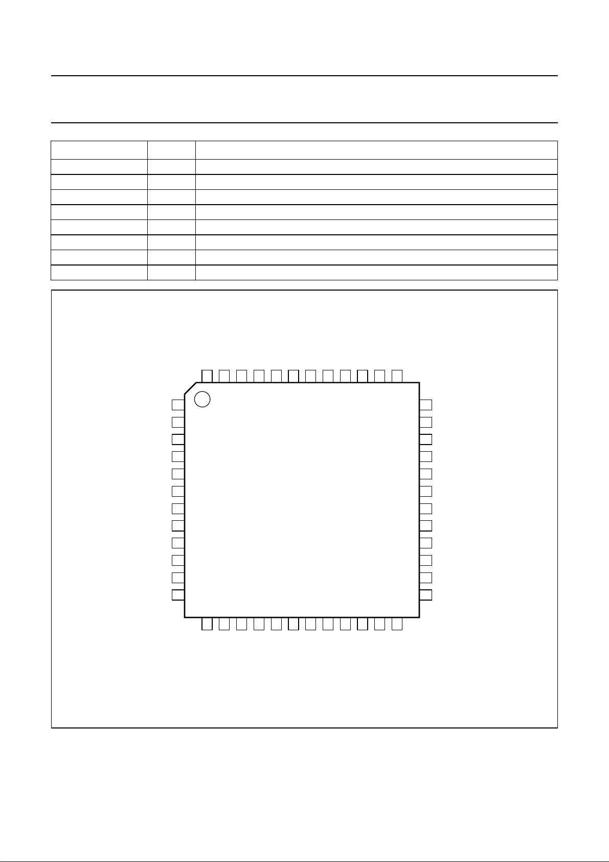
PINNING
SYMBOL PIN DESCRIPTION
RIPPLE 1 ripple capacitor input
AM-RFI 2 AMRF input
FM-RFO 3 parallel tuned FMRF circuit to ground
RFGND1 4 RF ground 1 and substrate
CGND 5 counter ground
FMOSC/COUNTI 6 parallel tuned FM-oscillator circuit to ground/counter input
AMOSC 7 parallel tuned AM-oscillator circuit to ground
V
CC1
TUNE 9 tuning current output
VCO 10 voltage controlled oscillator input
AFO 11 AM/FM AF output (output impedance typical 5 kΩ)
MPXI 12 stereo decoder input (input impedance typical 150 kΩ)
LFI 13 loop filter input
MUTE 14 mute input
AFLO 15 left channel output (output impedance typical 4.3 kΩ)
AFRO 16 right channel output (output impedance typical 4.3 kΩ)
PILFIL 17 pilot detector filter input
IFGND 18 ground of IF, detector and MPX stage
FMDEM 19 ceramic discriminator input
AFC
(n)
AFC
(p)
FSI 22 field strength indicator
V
CC2
n.c. 24 not connected
V
DDD
MO/ST 26 mono/stereo and tuning indication output
XTAL 27 crystal input
DGND 28 digital ground
BUS-CLOCK 29 bus-clock input
DATA 30 bus data input/output
WRITE-ENABLE 31 bus write-enable input
P0 32 programmable output port (P0)
P1 33 programmable output port (P1)
AFC 34 450 kHz LC circuit
n.c. 35 not connected
FM-IFI2 36 FMIF input 2 (input impedance typical 330 Ω)
V
STAB(B)
FM-IFO1 38 FMIF output 1 (output impedance typical 330 Ω)
AM-IFI/O2 39 input/output to IF-Tank (IFT); output: current source
FM-IFI1 40 FMIF input 1 (input impedance typical 330 Ω)
8 supply voltage
20 AFC negative output
21 AFC positive output
23 supply voltage for tuning
25 digital supply voltage
37 internal stabilized supply voltage (B)
2000 Feb 02 5
Philips Semiconductors Product specification
Self Tuned Radio (STR) TEA5757HL; TEA5759HL
SYMBOL PIN DESCRIPTION
V
STAB(A)
FM-ON/OFF 42 FM ON/OFF port
FM-MIXER 43 ceramic filter output (output impedance typical 330 Ω)
AM-MIXER 44 open-collector output to IFT
AM-IFI1 45 IFT or ceramic filter input (input impedance typical 3 kΩ)
RFGND2 46 FMRF ground 2
FM-RFI 47 FMRF aerial input (input impedance typical 40 Ω)
AGC 48 AGC capacitor input
handbook, full pagewidth
41 internal stabilized supply voltage (A)
RIPPLE
AM-RFI
FM-RFO
RFGND1
CGND
FMOSC/COUNTI
AMOSC
V
CC1
TUNE
VCO
AFO
MPXI
AGC
FM-RFI
RFGND2
AM-IFI1
AM-MIXER
FM-MIXER
48
47
46
45
44
43
1
2
3
4
5
6
7
8
9
10
11
12
13
14
15
LFI
MUTE
AFLO
TEA5757HL;
TEA5759HL
16
17
AFRO
PILFIL
18
IFGND
STAB(A)
FM-ON/OFF
V
42
41
20
19
(n)
AFC
FMDEM
FM-IFI1
40
21
(p)
AFC
AM-IFI/O2
39
22
FSI
STAB(B)
FM-IFO1
V
38
37
23
24
n.c.
CC2
V
36
FM-IFI2
35
n.c.
34
AFC
33
P1
32
P0
31
WRITE-ENABLE
30
DATA
29
BUS-CLOCK
28
DGND
27
XTAL
26
MO/ST
25
V
DDD
MHB607
Fig.2 Pin configuration.
2000 Feb 02 6

Philips Semiconductors Product specification
Self Tuned Radio (STR) TEA5757HL; TEA5759HL
FUNCTIONAL DESCRIPTION
The TEA5757HL; TEA5759HL is an integrated AM/FM
stereo radio circuit including digital tuning and control
functions.
The radio
The AM circuit incorporates a double balanced mixer, a
one-pin low-voltage oscillator (up to 30 MHz) and is
designed for distributed selectivity.
The AM input is designed to be connected to the top of a
tuned circuit. AGC controls the IF amplification and for
large signals it lowers the input impedance of the AM
front-end.
The first AM selectivity can be an IF-Tank (IFT) as well as
anIFT combined withaceramic filter; thesecond one is an
IFT.
The FM circuit incorporates a tuned RF stage, a double
balanced mixer, a one-pin oscillator and is designed for
distributed IF ceramic filters. The FM quadrature detector
uses a ceramic resonator.
The TEA5757HL; TEA5759HL can also be used with an
external FM front-end circuit. The external front-end is
activatedby the FM-ON/OFF signal. The AFC circuit in the
TEA5757HL; TEA5759HL provides a tuning voltage to
drive the VCOof the externalFM front-end.The frequency
of the external VCO is counted in the Self Tuned Radio
(STR) tuning system.
The PLL stereo decoder incorporates a signal dependent
stereo-blend circuit and a soft-mute circuit.
PRESET OPERATION
Inpreset mode, themicrocontroller has toload information
suchas frequency band,frequency and mono/stereo.This
information has to be sent via the bus to the STR.
The internal algorithm controls the tuning sequence as
follows:
1. The information is loaded into a shift register, a
last-station memory and the counter.
2. The Automatic Frequency Control (AFC) is switched
off.
3. The counter starts counting the frequency and the
tuning voltage is varied until the desired frequency
roughly equals the real frequency.
4. The AFC is then switched on and the counter is
switched off.
5. The real frequency is more precisely tuned to the
desired frequency.
After the AFC has tuned the real frequency to the desired
frequency an in-lock signal can be generated. In order to
get a reliable in-lock signal, there are two parameters
measured: the field strength and the S-curve. The field
strength indicates the strength of the station and by
looking at the S-curve the system can distinguish false
in-locks from real in-locks (false in-locks occur on the
wrong slope of the S-curve).
In the event of fading orpulling thein-lock signal becomes
logic 0 and the synthesizer will be switched on again and
the algorithm will be repeated.
SEARCH OPERATION
Tuning
Thetuning concept of Self TunedRadio (STR) isbased on
FUZZY LOGIC: it mimics hand tuning (hand tuning is a
combination of coarse and fine tuning to the qualitatively
best frequency position). As a consequence the tuning
system is very fast.
The tuning algorithm, which is controlled by the sequential
circuit (see Fig.1), is completely integrated; so there are
only a few external components needed.
The bus and the microcontroller can be kept very simple.
The bus only consists of three wires (BUS-CLOCK, DATA
and WRITE-ENABLE). The microcontroller must basically
give two instructions:
• Preset operation
• Search operation.
2000 Feb 02 7
During a search operation, the only action the
microcontroller has to take is: sending the desired band
plus the direction and the search sensitivity level to the
STR. The search operation is performed by the charge
pump until an in-lock signal is generated (combination of
measuring the field strength and the S-curve). The AFC
then fine tunes to the station. The frequency belonging to
thefound station willbecounted by the counterand written
into the last-station memory and the shift register of the
counter. At this time the frequency is available in the shift
register and can be read by the microcontroller.
The microcontroller decides whether the frequency is
withinthedesired frequency band. Ifso,thisfrequency can
be stored under a preset and if not, a new search action
should be started.
Philips Semiconductors Product specification
Self Tuned Radio (STR) TEA5757HL; TEA5759HL
Toensure that the search functionoperates correctly underall conditions thefollowing search sequencemust be applied:
• Store the current frequency in the memory
• Issue the search command
• Wait for data valid and read the new frequency
• If the new frequency is the same as the stored frequency, issue a preset step (e.g. 50 kHz) and start the search
sequence again.
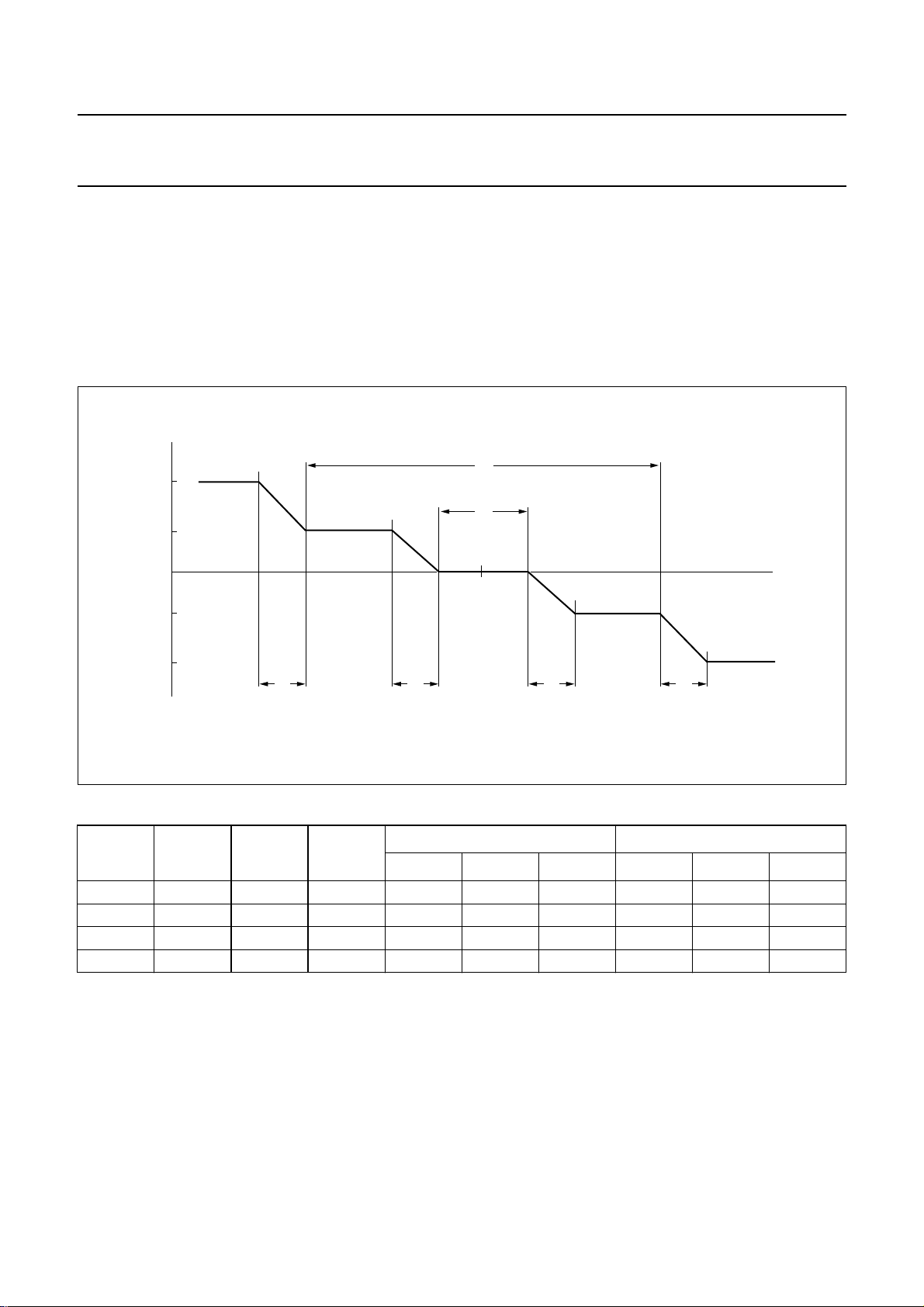
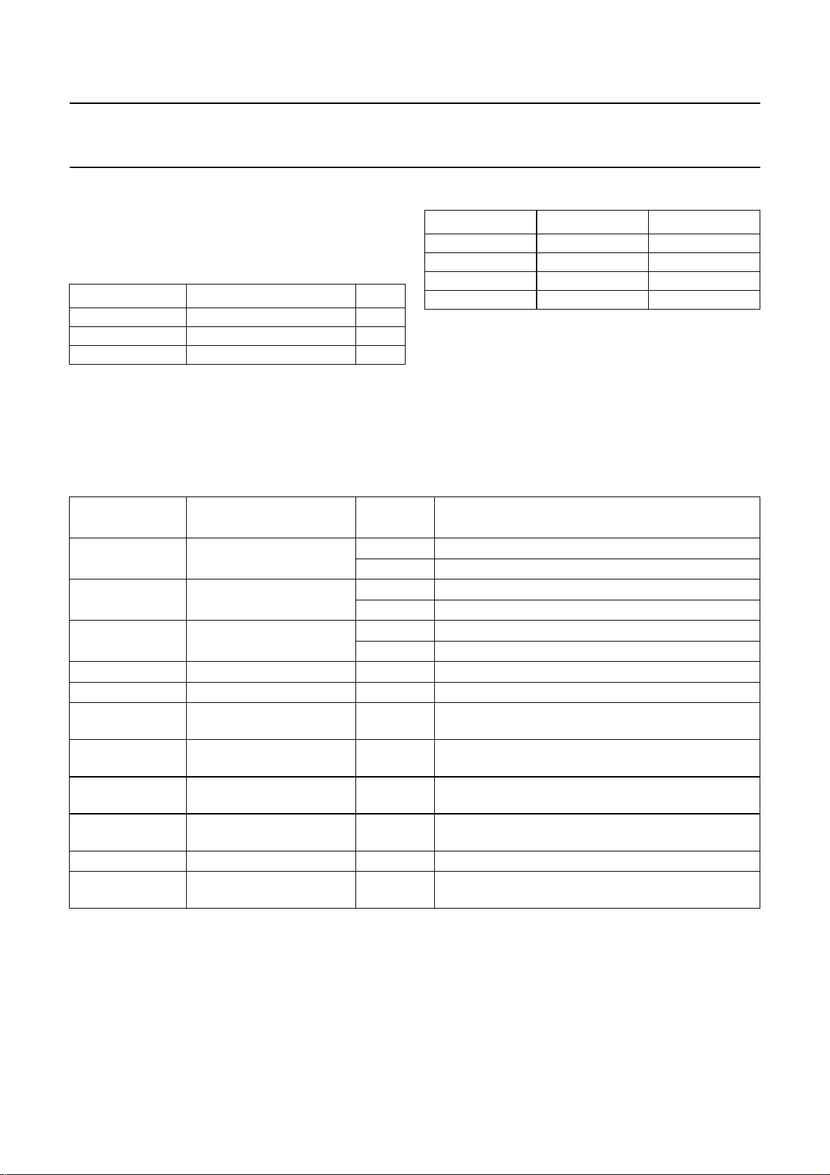
TUNING CURRENTS FOR DIFFERENT CONDITIONS
handbook, full pagewidth
I
9
I
B
I
A
−I
A
−I
B
R
R
W
2
W
1
f
c
R R
f
MHB641
Fig.3 Tuning currents.
Table 1 Tuning currents
BAND
SELECT
W
1
(kHz)
W
2
(kHz)
R
(kHz)
MIN. TYP. MAX. MIN. TYP. MAX.
IA (µA) IB (µA)
FM 25 200 12.5 2 2.5 3 54 80 100
MW 3 64 1 2 2.5 3 54 80 100
LW 1 64 1 2 2.5 3 54 80 100
SW 1 64 1 0.4 0.5 0.7 12 16 20
2000 Feb 02 8
Philips Semiconductors Product specification
Self Tuned Radio (STR) TEA5757HL; TEA5759HL
Description of the bus
The TEA5757HL; TEA5759HL radio has a bus which
consists of three wires, as shown in Table 2.
Table 2 Bus signals
SIGNAL DESCRIPTION PIN
BUS-CLOCK software driven clock input 29
DATA data input/output 30
WRITE-ENABLE write/read input 31
These three signals, together with the mono/stereo pin
(MO/ST; pin 26), communicate with the microcontroller.
The mono/stereo indicator has two functions, which are
controlled by the BUS-CLOCK, as shown in Table 3.
Table 4 Explanation of the shift register bits
BIT DESCRIPTION
S.24 (MSB) search start/end 0 after a search when a station is found or after a preset
D.23 search up/down 0 indicates if the radio has to search down
M.22 mono/stereo 0 stereo is allowed
B0.21 band see Table 5 selects FM/MW/LW/SW band
B1.20 band see Table 5 selects FM/MW/LW/SW band
P0.19 port note 1 user programmable bits which e.g. can be used as
P1.18 port note 1 user programmable bits which e.g. can be used as
S0.17 search-level of station see Table 6 determines the locking field strength during an
S1.16 search-level of station see Table 6 determines the locking field strength during an
15 dummy − buffer
F.14 to F.0 (LSB) frequency − determine the tuning frequency of the radio;
LOGIC
STATE
1 during the search action
1 indicates if the radio has to search up
1 mono is required (radio switched to forced mono)
Table 3 Bus-clock functions
BUS-CLOCK MO/ST (PIN 26) RESULT
LOW LOW stereo
LOW HIGH mono
HIGH LOW tuned
HIGH HIGH not tuned
The TEA5757HL; TEA5759HL has a 25-bit shift register;
see Table 4 for an explanation of the shift register bits.
If in search mode no transmitter can be found, all
frequency bits of the shift register are set to logic 0.
The bus protocol is illustrated in Figs 4 and 5.
RESULT
band switch driver
band switch driver
automatic search, automatic store or manual search
automatic search, automatic store or manual search
see Table 7 for the bit values
Note
1. The output pins 32 and 33 can drive currents up to 5 mA; bits P0.19 and P1.18 control the output voltage of the
control pins P0 (pin 32) and P1 (pin 33):
a) Bit P0.19 LOW sets P0 (pin 32) to LOW.
b) Bit P0.19 HIGH sets P0 (pin 32) to HIGH.
c) Bit P1.18 LOW sets P1 (pin 33) to LOW.
d) Bit P1.18 HIGH sets P1 (pin 33) to HIGH.
2000 Feb 02 9
Philips Semiconductors Product specification
Self Tuned Radio (STR) TEA5757HL; TEA5759HL
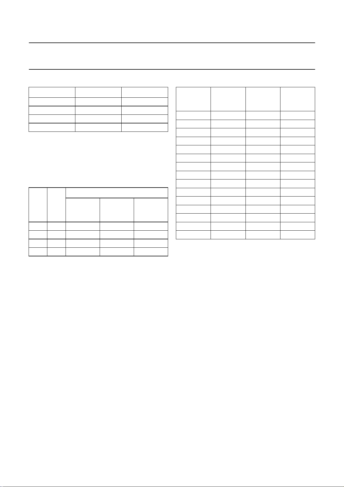
Table 5 Truth table for bits B0.21 and B1.20
B0.21 B1.20 BAND SELECT
00FM
(1)
01MW
10LW
11SW
Note
1. When FM is selected, the control output FM-ON/OFF
(pin 42) is pulled to ground to switch-on the external
FM front-end. Pin 42 is an open-collector pin with a
series resistor R = 500 Ω.
Table 6 Truth table for bits S1.16 and S0.17
SIGNAL RECEPTION
S1.16 S0.17
FM IF
INPUT
(µV)
FM RF
INPUT
(µV)
AM RF
INPUT
(µV)
0 0 >50 >5 >28
0 1 >100 >10 >40
1 0 >300 >30 >63
1 1 >1500 >150 >1000
Table 7 Values for bits F.14 to F.0
BIT BIT VALUEFMVALUE
(1)
(kHz)
F.14 2
F.13 2
F.12 2
F.11 2
F.10 2
F.9 2
F.8 2
F.7 2
F.6 2
F.5 2
F.4 2
F.3 2
F.2 2
F.1 2
F.0 2
14
13
12
11
10
9
8
7
6
5
4
3
2
1
0
− 16384
102400 8192
51200 4096
25600 2048
12800 1024
6400 512
3200 256
1600 128
800 64
400 32
200 16
100 8
50 4
25 2
12.5 1
Notes
1. FM value of the affected oscillators:
a) FM VALUE = FMRF + FMIF (for TEA5757HL).
b) FM VALUE = FMRF − FMIF (for TEA5759HL).
2. AM value of the affected oscillators:
AM VALUE = AMRF + AMIF.
AM
VALUE
(kHz)
(2)
2000 Feb 02 10
Philips Semiconductors Product specification
Self Tuned Radio (STR) TEA5757HL; TEA5759HL
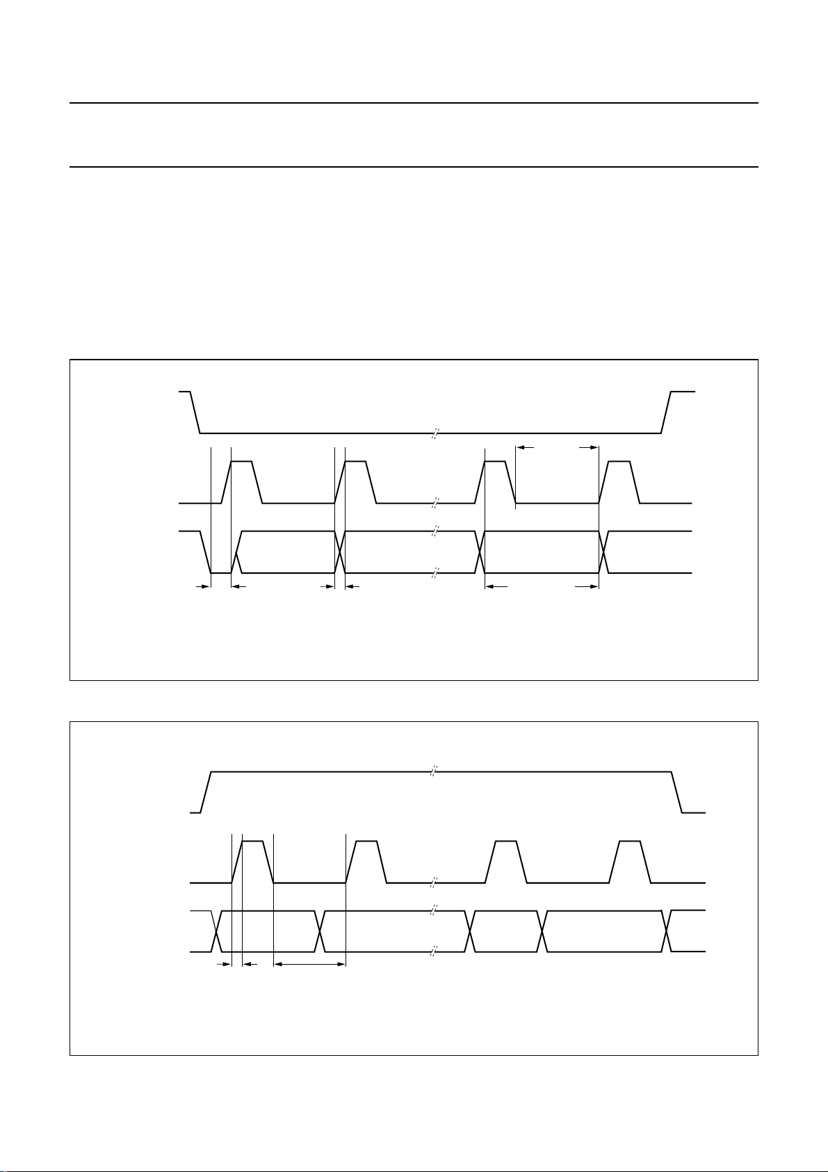
READING DATA
While WRITE-ENABLE is LOW data can be read by the
microcontroller. At a rising edge of the BUS-CLOCK, data
is shifted out of the register. This data is available from the
point where the BUS-CLOCK is HIGH until the next rising
edge of the BUS-CLOCK occurs (see Fig.4).
To read the entire shift register 24 clock pulses are
necessary.
handbook, full pagewidth
WRITE-ENABLE
BUS-CLOCK
DATA
data shiftdata available after search ready
MSB is LOW
WRITING DATA
While WRITE-ENABLE is HIGH the microcontroller can
transmit data to the TEA5757HL; TEA5759HL (hard mute
is active). Ata rising edge of theBUS-CLOCK, the register
shifts and accepts one bit into LSB. At clock LOW the
microcontroller writes data (see Fig.5).
To write the entire shift register 25 clock pulses are
necessary.
data read
data available
MBE817
ndbook, full pagewidth
WRITE-ENABLE
BUS-CLOCK
DATA
Fig.4 Read data.
MBE818
data changedata shift
Fig.5 Write data.
2000 Feb 02 11
Philips Semiconductors Product specification
Self Tuned Radio (STR) TEA5757HL; TEA5759HL
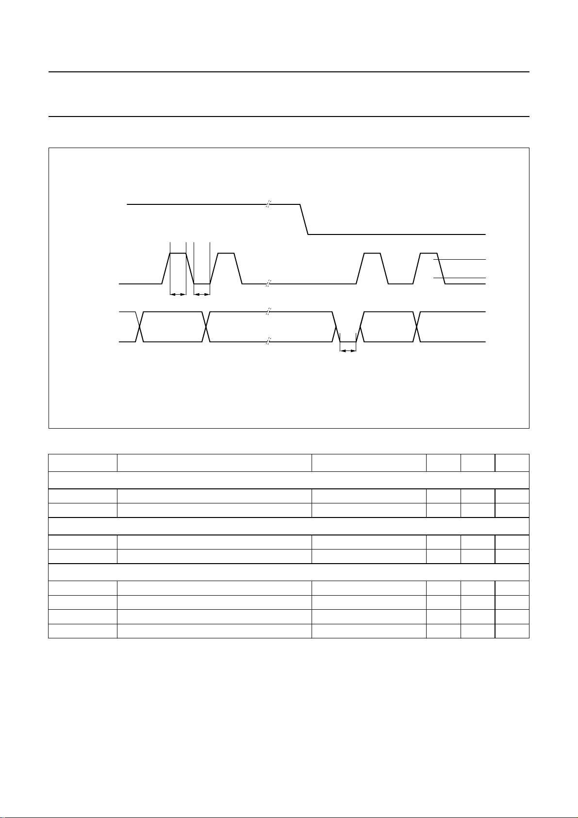
BUS TIMING
handbook, full pagewidth
WRITE-ENABLE
V
BUS-CLOCK
DATA
t
HIGHtLOW
IH
V
IL
t
da
MBE819
Fig.6 Bus timing.
Table 8 Digital inputs
SYMBOL PARAMETER CONDITIONS MIN. MAX. UNIT
Digital inputs
V
IH
V
IL
HIGH-level input voltage 1.4 − V
LOW-level input voltage − 0.6 V
Digital outputs (open-collector)
I
OL
V
OL
LOW-level output current − 1000 µA
LOW-level output voltage IOL= 600 µA − 0.6 V
Timing
f
clk
t
HIGH
t
LOW
t
da
clock input − 300 kHz
clock HIGH time 1.67 −µs
clock LOW time 1.67 −µs
shift register available after ‘search ready’ − 14 µs
2000 Feb 02 12
 Loading...