

Philips TDA8753A Datasheet

INTEGRATED CIRCUITS
DATA SH EET
TDA8753A
YUV 8-bit analog-to-digital interface
Product specification
Supersedes data of 1995 Mar 22
File under Integrated Circuits, IC02
1996 Jan 12
Philips Semiconductors Product specification
YUV 8-bit analog-to-digital interface TDA8753A
FEATURES
• Triple analog-to-digital converter
• 8-bit resolution
• Sampling rate up to 20 MHz
• Power dissipation of 500 mW (typical)
• Internal clamp functions
• 4:1:1 output data encoder
• Y binary output
• U, V two's complement outputs
• Sample rate converter permits programmable horizontal
compression factors from 1 to 2
• Serial microcontroller interface
• TTL compatible inputs.
APPLICATIONS
• High-speed analog-to-digital conversion for video signal
digitizing in 4 :1:1 format
• 100 Hz improved definition TV for all formats
(4/3, 16/9, 14/9 etc.).
GENERAL DESCRIPTION
The TDA8753A is a monolithic CMOS 8-bit video
low-power analog-to-digital conversion interface for YUV
signals. It converts the YUV analog input signal into 8-bit
binary coded digital words in format 4 :1:1 at a sampling
rate of 20 MHz. All analog signal inputs are clamped.
The device includes a digital sample rate converter for
variable compression with a factor 1 to 2.
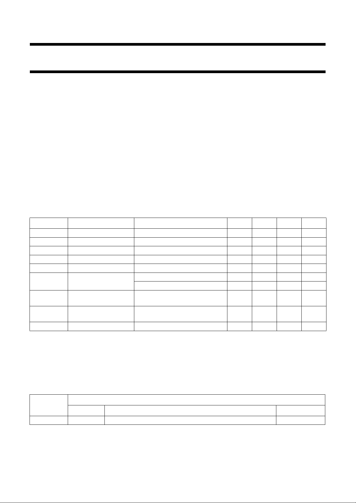
QUICK REFERENCE DATA
SYMBOL PARAMETER CONDITIONS MIN. TYP. MAX. UNIT
V
DDA
V
DDD
I
DDA
I
DDD
INL integral non-linearity f
DLE differential non-linearity f
SNR signal-to-noise ratio
analog supply voltage 4.75 5.0 5.25 V
digital supply voltage 4.75 5.0 5.25 V
analog supply current − 55 63 mA
digital supply current − 45 55 mA
= 16 MHz; ramp input −±0.75 − LSB
clk
= 16 MHz; ramp input; Y −±0.5 0.75 LSB
clk
= 16 MHz; ramp input; U and V −±0.6 ±0.9 LSB
f
clk
note 1 43 −−dB
without harmonics
f
clk
maximum conversion
20 −−MHz
rate
P
tot
total power dissipation note 2 − 500 650 mW
Notes
1. The signal-to-noise ratio without harmonics is measured using a 16 MHz clock frequency. This value is given for a
4.43 MHz input frequency on the Y channel (1.5 MHz on the U and V channels).
2. The external resistor (between V
DDA
) fixing internal static currents influences P
ref
. The value of the resistor
tot
and I
should be 5.6 kΩ (5%).
ORDERING INFORMATION
TYPE
NUMBER
NAME DESCRIPTION VERSION
PACKAGE
TDA8753A SDIP42 plastic shrink dual in-line package; 42 leads (600 mil) SOT270-1
1996 Jan 12 2
Philips Semiconductors Product specification
YUV 8-bit analog-to-digital interface TDA8753A
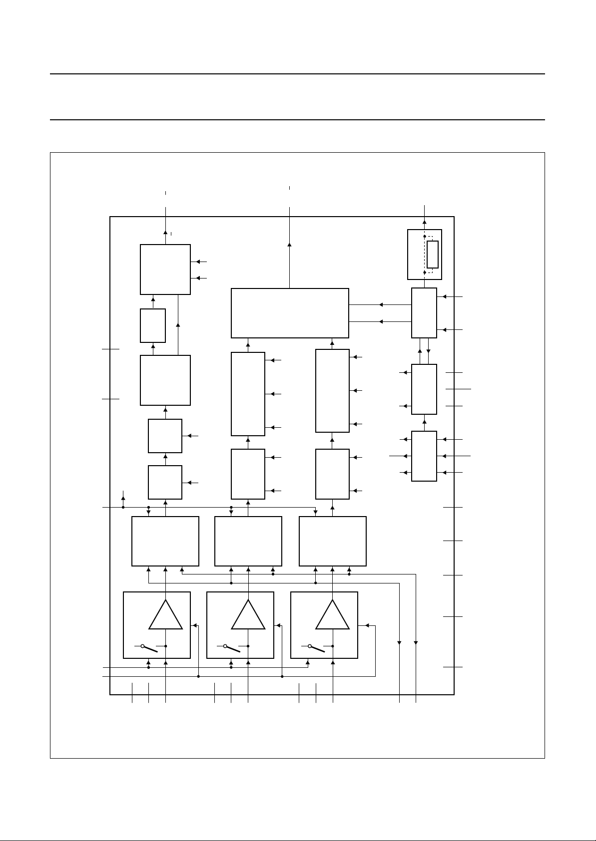
BLOCK DIAGRAM
SSD2
V
910
V
16
Y0 Y7
1 8
MIXER
DIFF
FILTER
LOW-PASS
PRE-
FILTER
DELAY
SIGN DELTA
ON/OFF
DELAY
12/14
INTERPOLATION
DOWNSAMPLING
AND
CORING
PREFILTER
UV0 UV1
11/13
U AND V
FORMATTER
ON/OFF NOTCH HOLD DELTA RESET
INTERPOLATION
DOWNSAMPLING
NOTCH HOLD DELTA RESET
AND
CORING
PREFILTER
ON/OFF
PHI
ENABLE
DELAY
ON/OFF NOTCH DELTA SIGN
WEO
MEMORY
INTERFACE
HOLD
DTO
SERIAL
INTERFACE
17
DELAY
RESET
MBE424
ref
MSCAN WEIH
MODE1
22 21 23
V50 MODE0
UPCL
41 40 42 19 18
handbook, full pagewidth
Fig.1 Block diagram.
SSD1 UPDA
V
CLAMP CLK DDD2
ref
I
CLAMP CIRCUIT
2027
39
37
SSA1
DDA1
V
V
ADC
8 BIT
x 1.5
38
INY
CLAMP CIRCUIT
34
DDA2
V
36
V
SSA2
ADC
8 BIT
x 1.5
35
INU
1996 Jan 12 3
ADC
8 BIT
x 1.5
CLAMP CIRCUIT
33
31
V
DDA3
SSA3
V
32
INV
TDA8753A
28
29
ref(L)
ref(H)
V
DEC
25 24
DDD1
V
15
SSD3
V
30
SSA4
V
26
SSA5
V
Philips Semiconductors Product specification
YUV 8-bit analog-to-digital interface TDA8753A
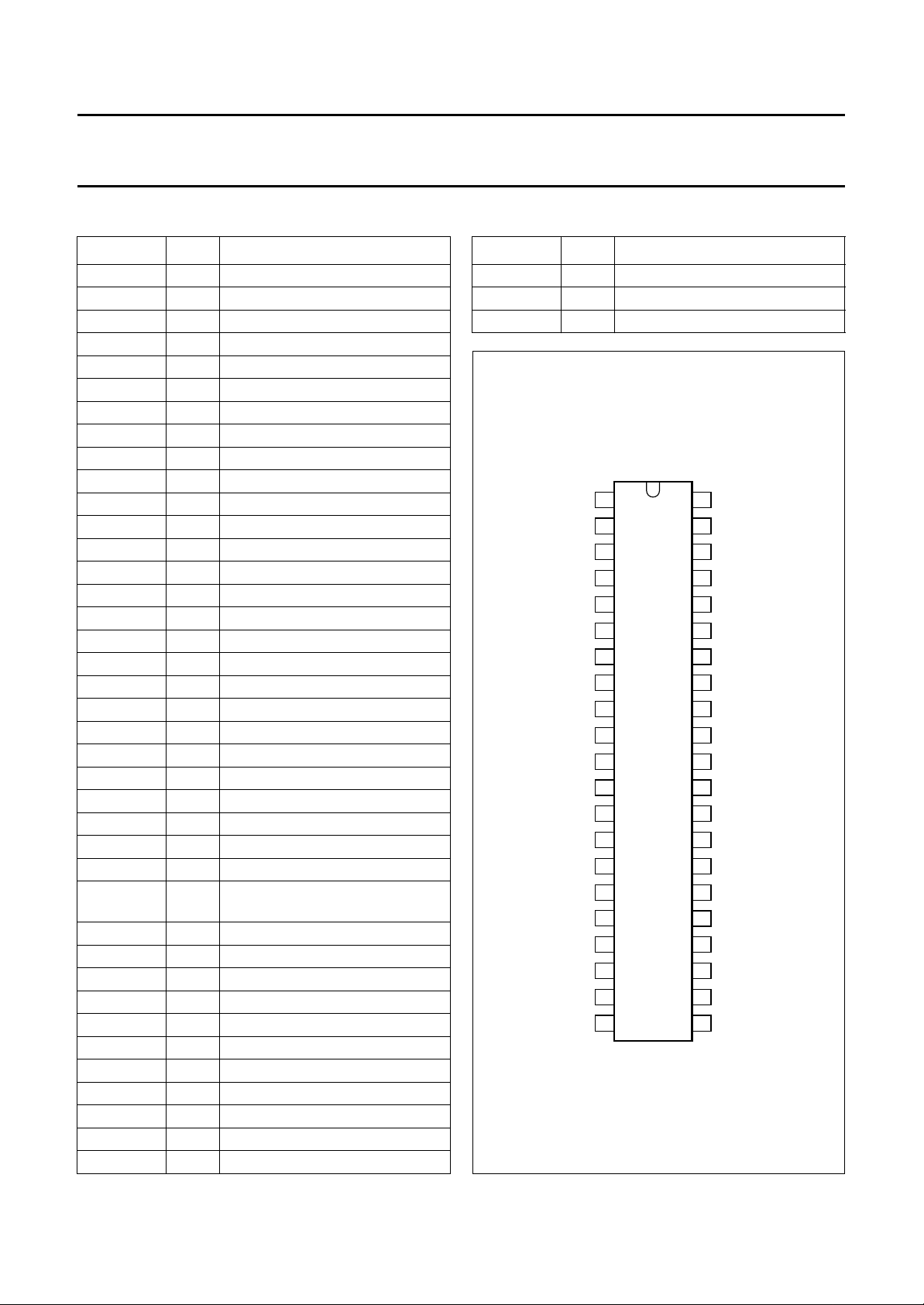
PINNING
SYMBOL PIN DESCRIPTION
Y7 1 Y data output, bit 7 (MSB)
Y6 2 Y data output, bit 6
Y5 3 Y data output, bit 5
Y4 4 Y data output, bit 4
Y3 5 Y data output, bit 3
Y2 6 Y data output, bit 2
Y1 7 Y data output, bit 1
Y0 8 Y data output, bit 0 (LSB)
V
V
DDD2
SSD2
9 digital supply voltage 2, (+5 V)
10 digital ground 2
U1 11 U data output, bit 1 (n)
U0 12 U data output, bit 0 (n − 1)
V1 13 V data output, bit 1 (n)
V0 14 V data output, bit 0 (n − 1)
V
SSD3
15 digital ground 3
CLK 16 clock input
WEO 17 write enable output
WEI 18 write enable input
H
ref
19 horizontal reference signal input
CLAMP 20 clamp control input
MODE1 21 test mode select
MODE0 22 test mode select
MSCAN 23 test pin
V
SSD1
V
DDD1
V
SSA5
I
ref
DEC
ref(L)
24 digital ground 1
25 digital supply voltage 1 (+5 V)
26 analog ground 5
27 current level reference
28 decoupling output from reference
LOW
V
V
V
ref(H)
SSA4
DDA3
29 reference voltage input (HIGH)
30 analog ground 4
31 analog supply voltage 3, (+5 V)
INV 32 V analog voltage input
V
V
SSA3
DDA2
33 analog ground 3
34 analog supply voltage 2 (+5 V)
INU 35 U analog voltage input
V
V
SSA2
DDA1
36 analog ground 2
37 analog supply voltage 1 (+5 V)
INY 38 Y analog voltage input
V
SSA1
39 analog ground 1
SYMBOL PIN DESCRIPTION
UPCL 40 control clock input
UPDA 41 serial interface data input
V50 42 data execution input
handbook, halfpage
V
CLAMP
MODE1
DDD2
V
SSD2
V
SSD3
WEO
Y7
Y6
Y5
Y4
Y3
Y2
Y1
Y0
U1
U0
V1
V0
CLK
WEI
H
ref
1
2
3
4
5
6
7
8
9
10
11
TDA8753A
12
13
14
15
16
17
18
19
20
MBE425
42
41
40
39
38
37
36
35
34
33
32
31
30
29
28
27
26
25
24
23
2221
V50
UPDA
UPCL
V
SSA1
INY
V
DDA1
V
SSA2
INU
V
DDA2
V
SSA3
INV
V
DDA3
V
SSA4
V
ref(H)
DEC
ref(L)
I
ref
V
SSA5
V
DDD1
V
SSD1
MSCAN
MODE0
Fig.2 Pin configuration.
1996 Jan 12 4

Philips Semiconductors Product specification
YUV 8-bit analog-to-digital interface TDA8753A
FUNCTIONAL DESCRIPTION
Analog-to-digital converter
The TDA8753 implements 3 independent CMOS 8-bit
analog-to-digital converters. The converters use a
multi-step approach with offset compensated
comparators.
Clamping
An internal clamping circuit is provided in each of the
3 analog channels. The analog pins INY, INV and INU are
switched to on-chip clamping levels during an active pulse
on the clamp input CLP.The clamping level in the
Y channel is code level 16. The clamping level in the U/V
channel is code level 128 (output code 0 in the
2's complement description) see Tables 3 and 4.
Sample rate converter
A sample rate converter is integrated in the TDA8753A to
facilitate programming of the horizontal aspect ratio which
can be varied from a factor 1 to 2.
This includes conversion from 16/9 to 14/9 and 4/3. In the
U/V channel a linear interpolation is sufficient because of
the four times oversampling.
The TDA8753A has three addressable control registers
which can be loaded via the signals UPDA and UPCL.
The format of this bus is fixed according to mode 0 of the
8051 family UART at 1 Mbaud (8 bits are transmitted, LSB
first).
Serial interface protocol
P
OWER-ON STATE
When powered up the SIO is in an unknown state and all
data in the registers is random. When signals are applied
to UPCL and UPDA in this state, the behaviour is
unpredictable. The only way to exit from this state to a
known state is apply a V50 signal to the TDA8753A.
I
NITIALIZATION STATE
From power-on or any other state, the INIT state is entered
(at the latest) one TDA8753A clock period after the end of
the V50 HIGH state. In this state the F0, F1 and F2
TDA8753A registers are loaded with the values that are in
the corresponding line buffers BF0, BF1 and BF2. The first
time V50 is issued after power-on, this data is unknown.
After a rising UPCL edge has been detected, the address
reception state is entered.
Discrete time oscillator (DTO)
A discrete time oscillator is used to calculate for every
sample of the phase delay that is needed for a given
compression factor.
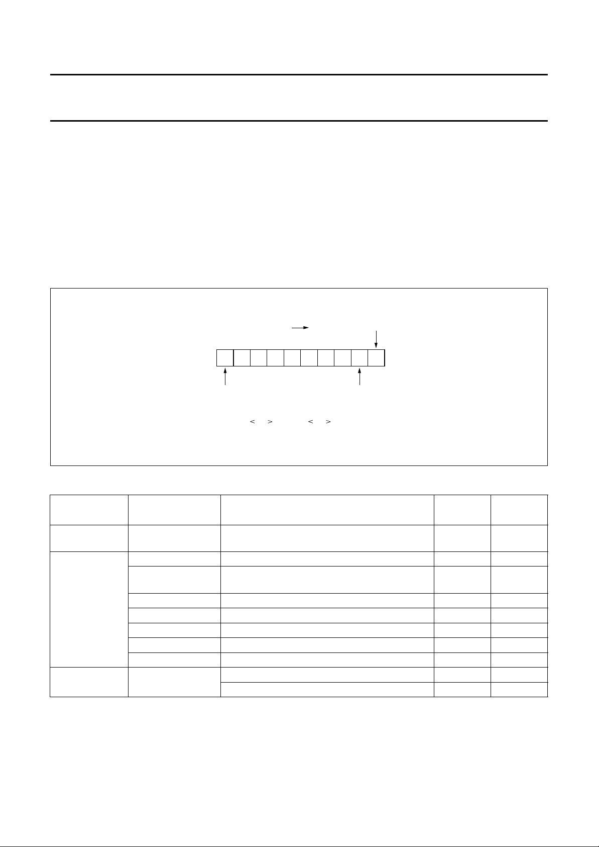
Serial interface (SIO)
All controls are sent to the TDA8753A via a serial
microprocessor interface. Data from this interface will be
made active at the vertical input pulse V50.
handbook, halfpage
11110010
first data bit
of data value
for address F2
register
last address
bit received
(in this example address received is F2 hex)
DDRESS RECEPTION STATE
A
Bits are counted at each rising UPCL edge. The next 8 bits
received on UPDA line are considered as address bits.
The address reception is illustrated in Fig.3.
incoming stream
first bit
received
MBE426
Fig.3 Address reception.
1996 Jan 12 5
Philips Semiconductors Product specification
YUV 8-bit analog-to-digital interface TDA8753A
The TDA8753A registers have address F0, F1 and F2
hexadecimal notation. Whenever the received address
(decoded on the first 8 bits received) is one of these, the
event is recorded in such a way that the next data received
by the TDA8753A will be captured in the line
buffer BF0, BF1 and BF2 respectively.
When 8 bits have been received, the data reception state
is entered. The address reception state can also be exited
at any time when V50 goes HIGH. The F0, F1 and F2
registers may not be loaded properly if there is some
activity in progress on the incoming line.
handbook, halfpage
110XXXXX
first bit of next
address stream
Data value is F2 0:2 = 110(DEL 0:2 )
incoming stream
D
ATA RECEPTION STATE
The next 8 bits are considered as data bits according to
the format of Fig.4.
When 8 data bits have been received, the data is recorded
in the BF0, BF1 or BF2 line buffers if the previous address
recorded was F0 hex, F1 hex or F2 hex respectively.
The bit count is then reset to zero and the address
reception state is entered. This state may be ended any
time when V50 goes HIGH but in that condition F0, F1 and
F2 registers may not be loaded properly.
last address
bit received
first data bit of value
(e.g. for address F2 register)
MBE427
Fig.4 Data reception.
Table 1 Data allocation
ADDRESS PARAMETER FUNCTION
F0H CF compression factor value will be (1 + cf/255)
NUMBER
OF BITS
8 7:0
POSITION
which results in a range from 1 to 2
F1H UV_CORING coring definition in U and V channels; see Table 5 2 1:0
UV_FILTER_TYPE notch filter selection in U and V channels
12
(0 = 4 MHz; 1 = 2 MHz)
PRE_ON luminance prefilter active 1 3
NOTCH_ON notch prefilter active 1 4
DTO_ON DTO control 1 5
SEL_DTO_RES select DTO reset (0 = WE; 1 = H
)16
ref
WEO_DEL_SEL select delay in WEO
F2H Y_VAR_DELAY luminance delay compression (see Table 5)
not used; load 0 5 7:2
BIT
1996 Jan 12 6
 Loading...