

Philips tda8050 n DATASHEETS

INTEGRATED CIRCUITS
DATA SH EET
TDA8050
QPSK transmitter
Product specification
Supersedes data of 1999 Jun 21
File under Integrated Circuits, IC02
1999 Dec 14
Philips Semiconductors Product specification
QPSK transmitter TDA8050
FEATURES
• Programmable gain
• PLL controlled carrier frequency
• 3-wire transmission bus
• 5 V supply voltage.
APPLICATIONS
• QPSK modulation.
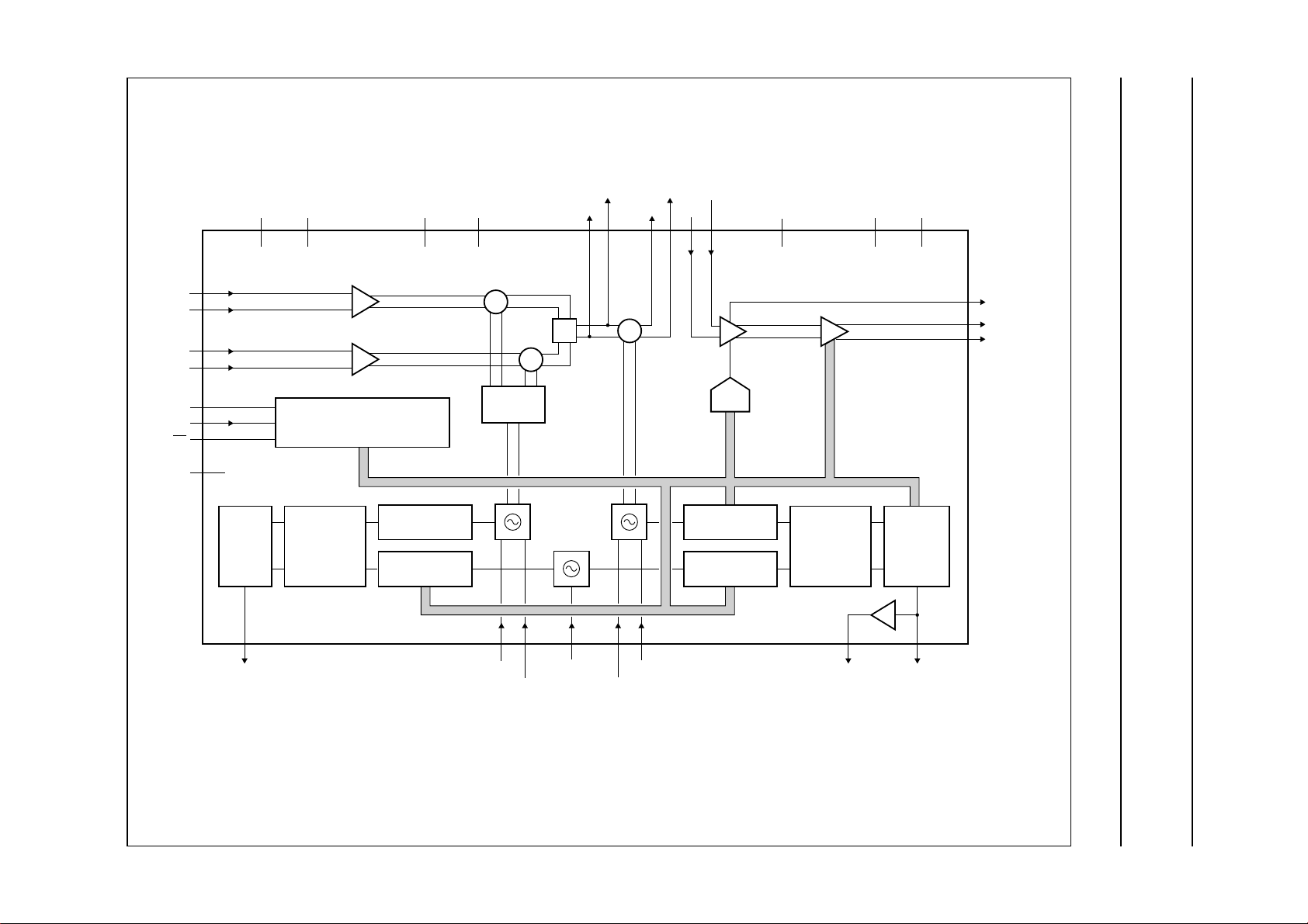
GENERAL DESCRIPTION
The QuadraturePhaseShift Keying(QPSK) transmitter is
a monolithic bipolar IC dedicated for quadrature
modulation of the I and Q signals. It includes:
• Two double-balanced mixers
• Symmetrical Voltage Controlled Oscillator (VCO) with
0 to 90 degree signal generation for modulation
• Phase-Locked Loop (PLL) for IF frequency control
• Conversion mixer
QUICK REFERENCE DATA
• PLL for RF frequency control
• Gain controlled output amplifier
• 3-wire bus and an output buffer.
Two PLLs are incorporated, the first PLL includes:
• Fixed main divider
• Crystal oscillator and its programmable reference
divider
• Phase/frequency detector combined with afixed charge
pump.
The second PLL includes:
• Divide-by-four preamplifier
• 12-bit programmable divider
• Crystal oscillator and its programmable reference
divider
• Phase/frequency detector combined with a ‘clever’
chargepump which drivesthe tuning amplifier,including
9 V output.
SYMBOL PARAMETER MIN. TYP. MAX. UNIT
V
CC
f
c
V
o(max)
f
xtal
f
ref(MOD)
f
step
T
amb
supply voltage 4.75 5.00 5.25 V
output centre frequency 5 − 40 MHz
maximum output level − 55 − dBmV
crystal frequency 1 − 4 MHz
reference frequency for modulator synthesizer − 250 − kHz
frequency step size for convertor synthesizer 50 − 500 kHz
operating ambient temperature 0 − 70 °C
ORDERING INFORMATION
TYPE
NUMBER
NAME DESCRIPTION VERSION
PACKAGE
TDA8050T SO32 plastic small outline package; 32 leads; body width 7.5 mm SOT287-1
1999 Dec 14 2
This text is here in white to force landscape pages to be rotated correctly when browsing through the pdf in the Acrobat reader.This text is here in
_white to force landscape pages to be rotated correctly when browsing through the pdf in the Acrobat reader.This text is here inThis text is here in
white to force landscape pages to be rotated correctly when browsing through the pdf in the Acrobat reader. white to force landscape pages to be ...
1999 Dec 14 3
BLOCK DIAGRAM
Philips Semiconductors Product specification
QPSK transmitter TDA8050
I_IN
I_INC
Q_IN
Q_INC
CLK
DATA
EN
LOCK
5
6
7
8
14
15
16
23
CHARGE
CP_MOD
DVCC13DGND
PUMP
RF_OUTC
AVCC1
18
AGND1
26
9
RF_OUT
2524 28
RF_INCIF_FILTC
RF_INIF_FILT
27
30 31
SW_CAP
MODULATOR CONVERTER
×
Σ
×
×
3-WIRE BUS TRANCEIVER
DIGITAL
PHASE
COMPARATOR
PROGRAMMABLE
FIXED
MAIN DIVIDER
REF DIVIDER
90° 0°
1/2
TDA8050
101211 17 22 21
TKAMOD
TKBMOD TKACONV
OSC_IN TKBCONV
DAC
PROGRAMMABLE
MAIN DIVIDER
PROGRAMMABLE
REF DIVIDER
AVCC2
32
DIGITAL
PHASE
COMPARATOR
20 19
TUNECONV CP_CONV
AGND2
29
PROGRAM-
MABLE
CHARGE
PUMP
4
1
OUTEN
3
BUF_OUTC
2
BUF_OUT
FCE181
handbook, full pagewidth
Fig.1 Block diagram.
Philips Semiconductors Product specification
QPSK transmitter TDA8050
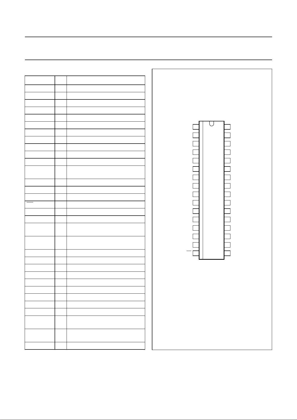
PINNING
SYMBOL PIN DESCRIPTION
OUTEN 1 output enable
BUF_OUT 2 output amplifier balanced output
BUF_OUTC 3 output amplifier balanced output
AGND2 4 converter analog ground 2
I_IN 5 I balanced input
I_INC 6 I balanced input
Q_IN 7 Q balanced input
Q_INC 8 Q balanced input
AGND1 9 modulator analog ground 1
TKAMOD 10 modulator VCO tank circuit input 2
TKBMOD 11 modulator VCO tank circuit input 1
CP_MOD 12 modulator charge pump output for
PLL loop filter
DVCC 13 digital supply voltage
CLK 14 3-wire bus serial control clock
DATA 15 3-wire bus serial control data input
EN 16 3-wire bus serial control enable
OSC_IN 17 crystal oscillator input
DGND 18 digital ground
CP_CONV 19 converter charge pump output for
PLL loop filter
TUNECONV 20 tuning voltage output for converter
VCO
TKBCONV 21 converter VCO tank circuit input 1
TKACONV 22 converter VCO tank circuit input 2
LOCK 23 lock detect signal
IF_FILT 24 IF balanced output to filter
IF_FILTC 25 IF balanced output to filter
AVCC1 26 modulator analog supply voltage
RF_OUTC 27 RF balanced output to filter
RF_OUT 28 RF balanced output to filter
AVCC2 29 converter analog supply voltage
RF_IN 30 RF balancedinput to programmable
amplifier
RF_INC 31 RF balanced input toprogrammable
amplifier
SW_CAP 32 switch capacitor
handbook, halfpage
BUF_OUTC
OUTEN
BUF_OUT
AGND2
AGND1
TKAMOD
TKBMOD
CP_MOD
I_IN
I_INC
Q_IN
Q_INC
DVCC
CLK
DATA
EN
1
2
3
4
5
6
7
8
9
10
11
12
13
14
15
16
TDA8050
Fig.2 Pin configuration.
FCE182
32
SW_CAP
31
RF_INC
RF_IN
30
AVCC2
29
RF_OUT
28
RF_OUTC
27
AVCC1
26
25
IF_FILTC
24
IF_FILT
23
LOCK
22
TKACONV
21
TKBCONV
20
TUNECONV
19
CP_CONV
18
DGND
17
OSC_IN
1999 Dec 14 4

Philips Semiconductors Product specification
QPSK transmitter TDA8050
FUNCTIONAL DESCRIPTION
The I and Q are balanced analog signals at a level of
400 mV (p-p). These are mixed by two double balanced
mixers with the output signal generated by a first local
oscillator providing the modulated signal.
The modulated signal is then filtered by an IF filter. This
filteredsignal together with asignalgenerated by asecond
local oscillator is converted by a balanced mixer to
produce the QPSK signal.
TheQPSK signal isamplified by again controlled amplifier
to a level suitable for transmission. The gain of the
controlled amplifier is buscontrolled and this amplifier can
be disabled when not transmitting to provide signal
attenuation.
The amplified signal is applied to an on-chip amplifier
having two balanced outputs (open collector) linked totwo
chip resistors (values 150 Ω), and 9 V. The balanced
outputs are designed to drive a 2 : 1 transformer
(Siemens V944) with a 75 Ω load giving an output level
of 55 dBmV.The output frequencyrange of the transmitter
is 5 to 40 MHz.
The frequency of the first local oscillator operates at twice
the frequency (i.e. 280 MHz) fixed by a Phase-Locked
Loop (PLL) implemented in the circuit.
Thefrequencyof the second localoscillatoroperatesin the
bandwidth 145 to 180 MHz and programmable due to a
PLL implemented in the circuit.
The VCO of both first and secondlocal oscillatorsrequires
an external LC tank circuit with two varicap diodes.
The data to the PLL is loaded in bursts framed by the
signal EN. Programming rising clock edges and their
appropriate data bits are ignored until EN goes active
(LOW). The internal latches are updated with the latest
programming data when EN returns inactive (HIGH).
The last 14 bits are stored in the programming register.
No check is made on the number of clock pulses received
during the time programming is enabled. A wrong active
clock edge will be generated causing a shift of data
bits, if EN goes HIGH while CLK is still LOW. At power
up, EN should beHIGH. The lock detector output LOCK is
HIGH when both PLLs are in lock.
The main divider ratio and the reference divider ratios are
provided via the serial bus. A control register controls the
Digital-to-Analog Converter (DAC), the output amplifier
and the charge pump currents (Tables 1, 2 and 3).
LIMITING VALUES
In accordance with the Absolute Maximum Rating System (IEC 134).
SYMBOL PARAMETER MIN. MAX. UNIT
V
CC
t
sc
V
max
V
o(tune)
V
o(buf)
P
tot
T
amb
T
stg
T
j(max)
supply voltage −0.3 +6.0 V
short-circuit time (every pin to VCCor GND) − 10 s
voltage on all pins except BUF_OUT, BUF_OUTC and TUNECONV −0.3 V
CC
V
output tuning voltage −0.3 +30 V
output buffer voltage on pins BUF_OUTand BUF_OUTC − 10 V
maximum power dissipation − 800 mW
operating ambient temperature 0 70 °C
storage temperature −40 +150 °C
junction temperature − 150 °C
1999 Dec 14 5

Philips Semiconductors Product specification
QPSK transmitter TDA8050
THERMAL CHARACTERISTICS
SYMBOL PARAMETER CONDITIONS VALUE UNIT
R
th(j-a)
HANDLING
Human Body Model (HBM): The IC pins withstand 2 kV except pins 27 and 28 (1750 V).
Machine Model (MM): The IC pins withstand 100 V.
CHARACTERISTICS
Measured in application circuit (see Fig.9) with the following conditions: V
values; unless otherwise specified.
SYMBOL PARAMETER CONDITIONS MIN. TYP. MAX. UNIT
Supply
V
CCA(mod)
I
CCA(mod)
V
CCA(conv)
I
CCA(conv)
I
CC(buf)
V
CCD
I
CCD
V
CC(tune)
Quadrature modulator I and Q inputs
V
I(DC)
V
i(p-p)
f
i(max)
Z
i(dif)
B
(1dB)
MODULATOR
f
c
∆A amplitude imbalance see Fig.3 −−±1dB
∆Φ phase imbalance −−±2 deg
LO
(sup)
Z
o(dif)
MODULATOR VOLTAGE CONTROLLED OSCILLATOR
f
osc(mod)
thermal resistance from junction to ambient in free air 63 K/W
=5V; T
CC
=25°C; all AC units are RMS
amb
modulator analog supply voltage 4.75 5 5.25 V
modulator analog supply current − 41 − mA
converter analog supply voltage 4.75 5 5.25 V
converter analog supply current − 48 − mA
buffer output supply current − 44 − mA
digital supply voltage 4.75 5 5.25 V
digital supply current − 22 − mA
tuning supply voltage −−9V
input DC level over the complete range of
− 0.5VCC− V
temperature
signal input level (balanced)
indicative − 400 500 mV
(peak-to-peak value)
I and Q maximum input frequency indicative − 10 − MHz
differential input impedance − 4.4 − kΩ
1 dB amplifier bandwidth indicative − 10 − MHz
output centre frequency −−140 MHz
LO suppression see Fig.3 −−28 − dBc
differential output impedance − 1.8 − kΩ
oscillation frequency VCO −−280 MHz
1999 Dec 14 6

Philips Semiconductors Product specification
QPSK transmitter TDA8050
SYMBOL PARAMETER CONDITIONS MIN. TYP. MAX. UNIT
Converter output
V
o
output level fi= 30 MHz; V
at I and Q inputs
∆V
o
output flatness fi= 5 to 40 MHz;
V
= 100 mV at I and Q
i(dif)
inputs
f
c
Z
o(dif)
output centre frequency 5 − 40 MHz
differential output impedance − 150 −Ω
IM3 3rd-order intermodulation distortion see Fig.4 −−−35 dBc
H
2
2nd-order harmonic of 5 to 40 MHz
signal
fi= 10 to 80 MHz;
V
= 100 mV at I and Q
i(dif)
inputs
H
3
3rd-order harmonic of 5 to 40 MHz
signal
fi= 15 to 120 MHz;
V
= 100 mV at I and Q
i(dif)
inputs
S
o
mixer spurious outputs of
5 to 40 MHz signal
fi= 5 to 40 MHz;
V
= 100 mV at I and Q
i(dif)
inputs
Converter voltage controlled oscillator
f
osc(min)
f
osc(max)
minimum oscillation frequency −−145 MHz
maximum oscillation frequency 180 −−MHz
Programmable gain and output buffer; note 1
Z
i(dif)
differential input impedance − 5.6 − kΩ
∆G output level step size −−2dB
∆Buf
o
output level adjust range Vi= 30 dBmV sine wave;
40 MHz at pin
RF_IN and RF_INC;
DAC = 0 to 31
V
∆V
o
o
output level − 55 − dBmV
output flatness fi= 5 to 40 MHz;
Vi= 30 dBmV sine wave;
DAC = 28
V
O(ENL)
V
O(ENH)
ISO disable isolation V
output controlled enable LOW output buffer on −−0.8 V
output controlled enable HIGH output buffer off 2.4 −−V
= 100 mV;
i(dif)
Vo= 55 dBmV; DAC = 28;
fi= 40 MHz; OE = 0.5
G
(max)
V
o(1dB)
H
2
maximum gain see Fig.5 − 22 − dB
1 dB compression point see Fig.5 60 −−dBmV
2nd-order harmonic of 5 to 40 MHz
signal
see Fig.6
f
=10to40MHz −−−45 dBc
i
f
= 54 to 120 MHz −−−35 dBc
i
i(dif)
= 100 mV
37.5 40 42.5 dBmV
−−2dB
−−−45 dBc
−−−45 dBc
−−−50 dBc
32 −−dB
−−2dB
−35 −−dBc
1999 Dec 14 7
Philips Semiconductors Product specification
QPSK transmitter TDA8050
SYMBOL PARAMETER CONDITIONS MIN. TYP. MAX. UNIT
H
3
Overall; note 1
Φ
osc
S
o
ISO
tot
C/N carrier to noise ratio at final output
Crystal oscillator
f
xtal
Z
i
V
I(DC)
Modulator synthesizer
f
ref(mod)
RDR1 reference divider ratio
ND1 fixed main divider ratio − 1120 −
I
cp
Converter synthesizer
f
step
RD2 fixed reference divider ratio − 2 −
RDR2 reference divider ratio
ND2 fixed main divider ratio − 4 −
NDR2 programmable main divider ratio see Table 4 290 − 3600
Three wire bus
V
IL
V
IH
Lock detect pin
V
o(lock)
V
o(unlock)
3rd-order harmonic of 5 to 40 MHz
signal
Fig.6
f
=15to40MHz −−−45 dBc
i
f
= 54 to 120 MHz −−−35 dBc
i
phase noise note 2;
at 10 kHz −−70 − dBc/Hz
at 100 kHz −−90 − dBc/Hz
spurious signals of 5 to 40 MHz
signal
fi= 5 to 40 MHz;
V
= 100 mV at I and Q
i(dif)
−−−50 dBc
inputs; Vo= 30 to 55 dBmV
total isolation at I/Q mid-range see Fig.7 −−−65 dBc
V
at 2 MHz from carrier
= 100 mV
i(dif)
Vo= 35 to 55 dBmV;
− 113 − dBc/Hz
fi= 26.5 MHz
crystal frequency note 3 1 − 4 MHz
input impedance f
= 4 MHz 600 1200 −Ω
xtal
DC input level − 2.9 − V
reference frequency − 250 − kHz
4 − 16
programmable
charge-pump current fixed − 0.30 − mA
frequency step size 50 − 500 kHz
see Table 4 4 − 160
programmable
LOW-level input voltage −−0.8 V
HIGH-level input voltage 2.4 −−V
output voltage (lock) − 5 − V
output voltage (unlock) − 0.02 − V
1999 Dec 14 8
 Loading...