

Philips TDA4886A Datasheet
INTEGRATED CIRCUITS
DATA SH EET
TDA4886A
140 MHz video controller with
2
I
C-bus
Product specification
File under Integrated Circuits, IC02
1998 Dec 04

Philips Semiconductors Product specification
140 MHz video controller with I2C-bus
CONTENTS
1 FEATURES
2 GENERAL DESCRIPTION
3 ORDERING INFORMATION
4 QUICK REFERENCE DATA
5 BLOCK DIAGRAM
6 PINNING
7 FUNCTIONAL DESCRIPTION
7.1 Signal input stage (input clamping, blanking
and clipping)
7.2 Electronic potentiometer stages
7.3 Output stage
7.4 Pedestal blanking
7.5 Output clamping, feedback references and
DAC outputs
7.6 Clamping and blanking pulses
7.7 On Screen Display (OSD)
7.8 Subcontrast adjustment, contrast modulation
and beam current limiting
7.9 I2C-bus control
7.10 I2C-bus data buffer
8 LIMITING VALUES
9 THERMAL CHARACTERISTICS
10 CHARACTERISTICS
11 I2C-BUS PROTOCOL
12 TEST AND APPLICATION INFORMATION
12.1 Test boards
12.2 Recommendations for building the application
board
13 INTERNAL CIRCUITRY
14 PACKAGE OUTLINE
15 SOLDERING
15.1 Introduction to soldering through-hole mount
packages
15.2 Soldering by dipping or by solder wave
15.3 Manual soldering
15.4 Suitability of through-hole mount IC packages
for dipping and wave soldering methods
16 DEFINITIONS
17 LIFE SUPPORT APPLICATIONS
18 PURCHASE OF PHILIPS I2C COMPONENTS
TDA4886A
1998 Dec 04 2

Philips Semiconductors Product specification
140 MHz video controller with I2C-bus
1 FEATURES
• 140 MHz pixel rate
• 2.8 ns rise time, 3.8 ns fall time
• I2C-bus control
• I2C-bus data buffer for synchronization of adjustments
• Grey scale tracking
• On Screen Display (OSD) mixing with 50 MHz pixel rate
• OSD contrast
• Negative feedback for DC-coupled cathodes
• Especially for AC-coupled cathodes
– Black level adaptable to kind of post amplifier
– Internal positive feedback
– DAC outputs for black level restoration.
• Integrated black level storage capacitors
• Beam current limiting
• Subcontrast/contrast modulation
• Pedestal blanking
• Sync clipping.
TDA4886A
2 GENERAL DESCRIPTION
The TDA4886A is a monolithic integrated RGB
pre-amplifier for colour monitor systems (e.g. 15" and 17")
with I2C-bus control and OSD. In addition to bus control,
beam current limiting and contrast modulation are
possible. The signals are amplified in order to drive
commonly used video modules or discrete solutions.
Individual black level control with negative feedback from
the cathode (DC coupling) or gradually adaptable black
level control with positive feedback and 3 DAC outputs for
external cut-off control (AC coupling) is possible.
With special advantages the circuit can be used in
conjunction with the TDA485X monitor deflection IC
family.
3 ORDERING INFORMATION
TYPE
NUMBER
TDA4886A SDIP24 plastic shrink dual in-line package; 24 leads (400 mil) SOT234-1
NAME DESCRIPTION VERSION
PACKAGE
1998 Dec 04 3

Philips Semiconductors Product specification
140 MHz video controller with I2C-bus
TDA4886A
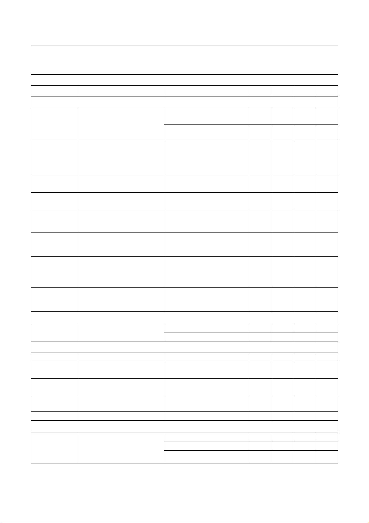
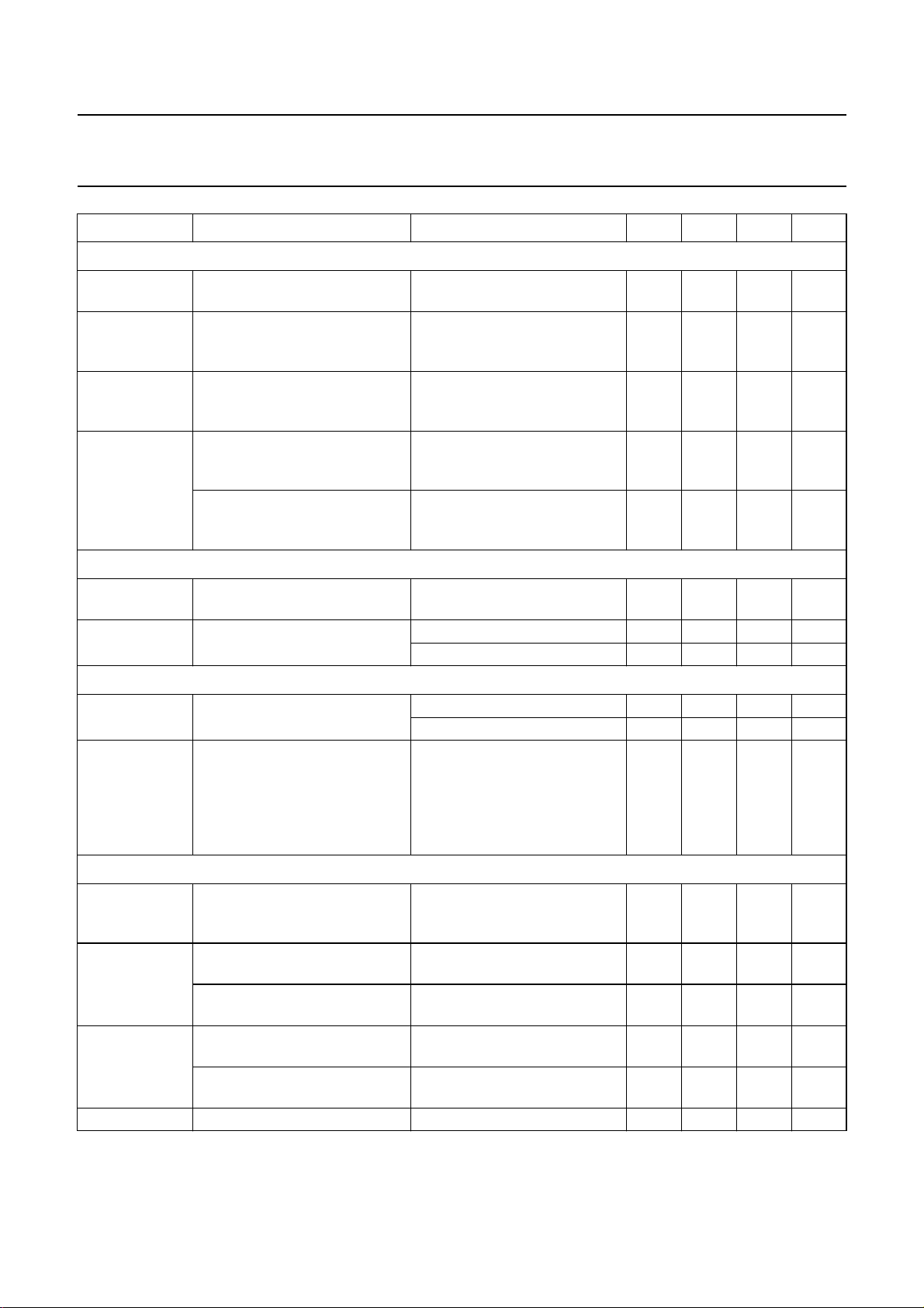
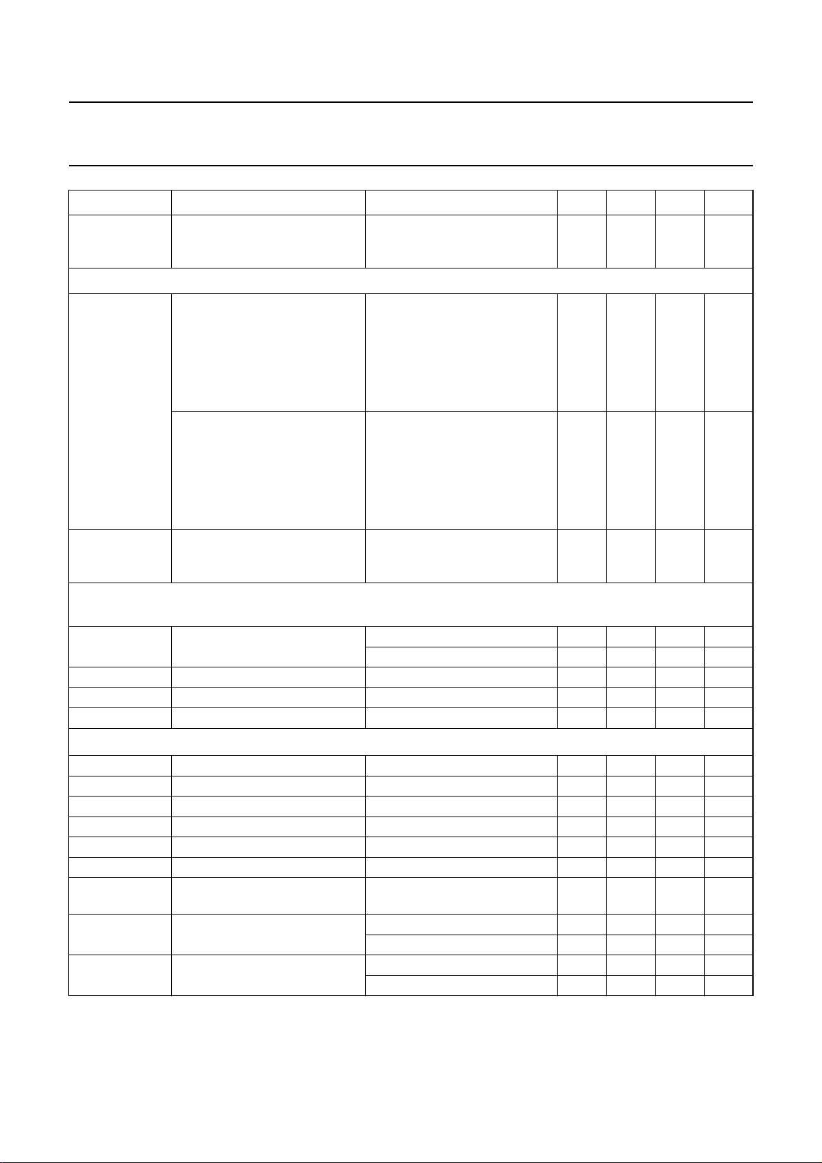
4 QUICK REFERENCE DATA
SYMBOL PARAMETER CONDITIONS MIN. TYP. MAX. UNIT
V
P
I
P
V
P1,2,3
I
P1,2,3
V
i(b-w)
supply voltage (pin 7) 7.6 8.0 8.8 V
supply current (pin 7) − 21 25 mA
channel supply voltage (pins 21, 18 and 15) 7.6 8.0 8.8 V
channel supply current (pins 21, 18 and 15) − 21 25 mA
input voltage
− 0.7 1.0 V
(black-to-white value; pins 6, 8 and 10)
V
o(b-w)
V
o(b-w)(max)
V
o
V
bl(DC)
nominal output voltage swing
(black-to-white value; pins 22, 19 and 16)
maximum output voltage swing
(black-to-white value; pins 22, 19 and 16)
output voltage level (pins 22, 19 and 16) 0.05 − VP− 1V
typical reference black level for DC coupling
nominal contrast;
− 2.8 − V
maximum gain
maximum contrast;
− 4.54 − V
maximum gain
control bit FPOL = 0 0.5 − 2.5 V
(pins 22, 19 and 16)
V
bl(AC)
typical reference black level for AC coupling
(pins 22, 19 and 16)
control bit FPOL = 1 and
PEDST = 0
BLH2 = 0; BLH1 = 0 − 0.77 − V
BLH2 = 0; BLH1 = 1 − 1.01 − V
BLH2 = 1; BLH1 = 0 − 1.25 − V
BLH2 = 1; BLH1 = 1 − 1.49 − V
I
o(sink)
I
o(source)
peak output sink current during fast signal transients −−20 mA
peak output source current during fast signal transients −40 −− mA
B bandwidth −3 dB (small signal) − 165 − MHz
t
r(o)
video rise time at signal outputs
− 2.8 − ns
(pins 22, 19 and 16)
t
f(o)
video fall time at signal outputs
− 3.8 − ns
(pins 22, 19 and 16)
dV
o
overshoot at signal outputs
minimum rise time 8 17 30 %
(pins 22, 19 and 16)
α
C
TR
ct(f)
C
o
crosstalk suppression by frequency f = 50 MHz 25 −− dB
contrast control related to nominal contrast −28 − +4.2 dB
tracking of output signals for contrast
− 0.0 0.5 dB
variation from maximum to minimum
G
C
BC brightness control (typical black level
gain control related to maximum gain −7.3 − 0dB
−10 − +30 %
voltage change related to nominal output
signal amplitude)
V
o(OSD)(max)
maximum OSD output voltage swing related
to nominal output voltage swing
maximum OSD contrast;
maximum gain
− 120 − %
(pins 22, 19 and 16)
C
OSD
OSD contrast control related to maximum
−12 − 0dB
OSD contrast
1998 Dec 04 4

This text is here in white to force landscape pages to be rotated correctly when browsing through the pdf in the Acrobat reader.This text is here in
d
_white to force landscape pages to be rotated correctly when browsing through the pdf in the Acrobat reader.This text is here inThis text is here in
white to force landscape pages to be rotated correctly when browsing through the pdf in the Acrobat reader. white to force landscape pages to be ...
1998 Dec 04 5
book, full pagewidth
5 BLOCK DIAGRAM
140 MHz video controller with I
Philips Semiconductors Product specification
LIM
V
V
V
I1
I2
I3
24
6
8
10
input clamping
REGISTER
INPUT
CLAMPING
BLANKING
INPUT
CLAMPING
BLANKING
INPUT
CLAMPING
BLANKING
DISO
SDA SCL
12 13
6
I2C-BUS
PEDST
DISO
DISV
FPOL
BLH1
BLH2
fast
blanking
FBL OSD1OSD2OSD
CONTRAST MODULATION
OSD INPUT
1234
SUBCONTRAST
LIMITING
CONTRAST
CONTRAST
CONTRAST
3
6
6-BIT
DAC
OSD
CONTRAST
OSD
CONTRAST
OSD
CONTRAST
4 6 6 6 6
4-BIT
DAC
6-BIT
DAC
BRIGHTNESS
BLANKING
BRIGHTNESS
BRIGHTNESS
BRIGHTNESS
INPUT CLAMPING
VERTICAL BLANKING
511
6-BIT
DAC
GAIN
GAIN
GAIN
vertical
blanking
6-BIT
DAC
6-BIT
DAC
PEDESTAL
BLANKING
PEDST
PEDESTAL
BLANKING
PEDST
PEDESTAL
BLANKING
PEDST
blanking
TDA4886A
output
clamping
BLANKING
OUTPUT CLAMPING
HFBCLI
8
8-BIT
DAC
8
8-BIT
DAC
8
8-BIT
DAC
FPOL
FPOL
FPOL
FPOL
FPOL
FPOL
DISV
BLH2
BLH1
CHANNEL 1
REFERENCE
CHANNEL 2
REFERENCE
CHANNEL 3
REFERENCE
SUPPLY
V
P
FPOL
FPOL
FPOL
79
GND
21
22
23
18
19
20
15
16
17
14
MHB264
V
P1
V
O1
FB/R
V
P2
V
O2
FB/R
V
P3
V
O3
FB/R
GNDX
2
1
2
3
C-bus
TDA4886A
Fig.1 Block diagram.

Philips Semiconductors Product specification
140 MHz video controller with I2C-bus
6 PINNING
SYMBOL PIN DESCRIPTION
FBL 1 fast blanking input for OSD insertion
OSD
1
OSD
2
OSD
3
CLI 5 input clamping; vertical blanking
V
I1
V
P
V
I2
GND 9 ground
V
I3
HFB 11 horizontal flyback input
SDA 12 I2C-bus serial data input/output
SCL 13 I
GNDX 14 ground channels 1, 2 and 3
V
P3
V
O3
FB/R
3
V
P2
V
O2
FB/R
2
V
P1
V
O1
FB/R
1
LIM 24 subcontrast, contrast modulation,
2 OSD input channel 1
3 OSD input channel 2
4 OSD input channel 3
input
6 signal input channel 1
7 supply voltage
8 signal input channel 2
10 signal input channel 3
(output clamping, blanking)
2
C-bus clock input
15 supply voltage channel 3
16 signal output channel 3
17 feedback input/reference voltage
output channel 3
18 supply voltage channel 2
19 signal output channel 2
20 feedback input/reference voltage
output channel 2
21 supply voltage channel 1
22 signal output channel 1
23 feedback input/reference voltage
output channel 1
beam current limiting input
handbook, halfpage
FBL
1
OSD
2
1
OSD
3
2
OSD
4
3
CLI
5
V
6
I1
TDA4886A
V
7
P
V
8
I2
GND
9
V
10
I3
HFB
11
SDA
12
MHB265
Fig.2 Pin configuration.
TDA4886A
LIM
24
FB/R
23
1
V
22
O1
V
21
P1
FB/R
20
2
V
19
O2
V
18
P2
FB/R
17
3
V
16
O3
V
15
P3
GNDX
14
SCL
13
1998 Dec 04 6

Philips Semiconductors Product specification
140 MHz video controller with I2C-bus
7 FUNCTIONAL DESCRIPTION
See block diagram (Fig.1) and definition of levels and
output signals (see Chapter “Characteristics” notes 1 to 3;
Figs 3 to 6).
7.1 Signal input stage (input clamping, blanking and clipping)
The RGB input signals with nominal signal amplitude of
0.7 V are capacitively coupled into the TDA4886A from a
low-ohmic source (75 Ω recommended) and actively
clamped to an internal DC voltage during signal black
level. Because of the high-ohmic input impedance of the
TDA4886A the coupling capacitor (which also functions as
a storage capacitor between clamping pulses) can be
relatively small (10 nF recommended). Very small input
currents will discharge the coupling capacitor resulting in
black output signals for missing input clamping pulses.
Composite signals will not disturb normal operation
because a clipping circuit cuts all signal parts below
black level.
A fast signal blanking stage belongs to the input stage
which is driven by several blanking pulses (see Section
“Clamping and blanking pulses”) and control bit DISV = 1.
During the off condition the internal reference black level
will be inserted instead of the input signals.
7.2 Electronic potentiometer stages
7.2.1 C
ONTRAST CONTROL (DRIVEN BY I
6-
BIT DAC)
The input signals related to the internal reference black
level can be simultaneously adjusted by contrast control
with a control range of typically 32 dB. The nominal
contrast setting is defined for 26H (4.2 dB below
maximum).
7.2.2 B
RIGHTNESS CONTROL (DRIVEN BY I
BIT DAC)
6-
With brightness control the video black level will be shifted
in relation to the reference black level simultaneously for
all three channels. With a negative setting (maximum 10%
of nominal signal amplitude) dark signal parts will be lost in
ultra black while for positive settings (maximum 30% of
nominal signal amplitude) the background will alter from
black to grey. The nominal brightness setting (10H) is no
shift. The brightness setting is also valid for OSD signals.
During blanking and output clamping the video black level
will be blanked to reference black level (brightness
blanking).
2
C-BUS,
2
C-BUS,
TDA4886A
7.2.3 G
AIN CONTROL (DRIVEN BY I
AND GREY SCALE TRACKING
Gain control is used for white point adjustment (correction
for different voltage to light amplification of the three colour
channels) and therefore individual for the three channels.
The video signals related to the reference black level can
be gain controlled within a range of typically 7.3 dB.
The nominal setting is maximum gain. The video signal is
the addition of the contrast controlled input signal and the
brightness shift. The gain setting is also valid for OSD
signals, thus the complete ‘grey scale’ is effected by gain
control.
7.3 Output stage
In the output stage the nominal input signal will be
amplified to 2.8 V output colour signal at nominal contrast
and maximum gain. The maximum input to output
amplification at maximum contrast and gain settings is
16.2 dB. By output clamping the reference black level
can be adjusted. In order to achieve fast rise and fall times
of the output signals with minimum crosstalk between the
channels, each output stage has its own supply voltage
pin.
7.4 Pedestal blanking
For the video portion the reference black level should
correspond to the ‘extended cut-off voltage’ at the
cathode. Nevertheless during vertical flyback retrace lines
may be visible, though blanking to spot cut-off is useful.
With control bit PEDST = 1 the pedestal black level will be
adjusted by output clamping instead of the reference black
level (see Fig.5). The pedestal black level is more negative
than the video black level at minimum brightness setting
and the voltage difference to reference black level is fixed.
7.5 Output clamping, feedback references and DAC outputs
The aim of the output clamping (pins FB/R
and FB/R3 with control bit FPOL = 0, internal feedback
with control bit FPOL = 1) is to set the reference black level
of the signal outputs to a value which corresponds to the
‘extended cut-off voltage’ of the CRT cathodes. With a lack
of output clamping pulses the integrated storage
capacitors will be discharged resulting in output signals
going to switch-off voltage. Feedback references are
driven by the I2C-bus.
2
C-BUS,6-BIT DAC)
, FB/R
1
2
1998 Dec 04 7

Philips Semiconductors Product specification
140 MHz video controller with I2C-bus
1. Control bit FPOL = 0
The cathode voltage (DC-coupled) is divided by a
voltage divider and fed back to the IC. During the
output clamping pulse it is compared with an
adjustable feedback reference voltage with a range of
approximately 5.77 to 4.05 V. Any difference will lead
to a reference black level correction (control bit
PEDST = 0) or pedestal black level correction (control
bit PEDST = 1) by charging or discharging the
integrated capacitor which stores the black level
information between the output clamping pulses.
The DC voltages of the output stages should be
designed in such a way that the reference black
level/pedestal black level is within the range of
0.5 to 2.5 V.
For correct operation it is necessary that there is
enough headroom for ultra black signals (negative
brightness setting, pedestal black level if control bit
PEDST = 1). Any clipping with the video supply
voltage at the cathode can disturb the signal rise/fall
times or the black level stabilization.
2. Control bit FPOL = 1
For applications with AC-coupled cathodes the signal
outputs are fed back internally. During the output
clamping pulse they are compared with a feedback
reference voltage of approximately 0.75, 1.0, 1.25 or
1.5 V (depending on the values of control bits BLH2
and BLH1). These values ensure a good adaptability
to discrete and integrated post amplifiers as well.
For black level restoration the DAC outputs (FB/R1,
FB/R2 and FB/R3) with a range of approximately
5.77 to 4.05 V can be used.
The use of pedestal blanking allows a very simple
black level restoration with a DC diode clamp instead
of a complicated pulse restoration circuit because the
pedestal black level is the most negative output signal.
7.6 Clamping and blanking pulses
The pin CLI of TDA4886A can be directly connected to
pin CLBL of e.g. TDA4855 sync processor for input
clamping pulses and vertical blanking pulses.
The threshold for the input clamping pulse (typical 3 V) is
higher than the threshold for the vertical blanking pulse
(typical 1.4 V) but there must be no blanking during input
clamping. Thus vertical blanking only is enabled if no input
clamping is detected. For this reason the input clamping
pulse must have rise/fall times faster than 75 ns/V during
the transition from 1.2 to 3.5 V and vice versa. The internal
vertical blanking pulse will be delayed by typical 270 ns.
TDA4886A
During the vertical blanking pulse at pin CLI signal
blanking, brightness blanking and with control bit
PEDST = 1 pedestal blanking will be activated. Input
clamping pulses during vertical blanking will not switch off
blanking.
For proper input clamping the input signals have to be at
black level during the input clamping pulse.
An input pulse at pin HFB (e.g. horizontal flyback pulse)
will be scanned with two thresholds. If the input pulse
exceeds the first one (typical 1.4 V) signal blanking,
brightness blanking and if control bit PEDST = 1
pedestal blanking will be activated. If the input pulse
exceeds the second one (typical 3 V) additionally output
clamping will be activated. The vertical blanking pulse can
also be mixed with the horizontal flyback pulse at pin HFB.
7.7 On Screen Display (OSD)
If the fast blanking input signal at pin FBL exceeds the
threshold (typical 1.4 V) the input signals are blanked
(signal blanking) and OSD signals are enabled. Then any
signal at pins OSD
threshold will create an insertion signal with an amplitude
of 120% of the nominal colour signal (approximately 74%
of the maximum colour signal). The amplitude can be
controlled by OSD contrast (driven by the I2C-bus) with a
range of 12 dB. The OSD signals are inserted at the same
point as the contrast controlled input signals and will be
treated with brightness and gain control like normal input
signals.
With control bit DISO = 1 the OSD signal insertion and fast
blanking (pin FBL) are disabled.
7.8 Subcontrast adjustment, contrast modulation and beam current limiting
The pin LIM is a linear contrast control pin which allows
subcontrast setting, contrast modulation and beam current
limiting. The maximum contrast is defined by the actual
I2C-bus setting. Input signals at pin LIM act on video and
OSD signals and do not affect the contrast bit resolution.
To achieve brightness uniformity over the screen, scan
dependent contrast modulation is possible.
, OSD2 or OSD3 exceeding the same
1
1998 Dec 04 8

Philips Semiconductors Product specification
140 MHz video controller with I2C-bus
7.9 I2C-bus control
The TDA4886A contains an I2C-bus receiver for several
control functions:
1. Contrast control with 6-bit DAC
2. Brightness control with 6-bit DAC
3. OSD contrast control with 4-bit DAC
4. Gain control for each channel with 6-bit DAC
5. Internal feedback reference and external reference
voltage control for each channel with 8-bit DAC
6. Control register with control bits BLH2, BLH1, FPOL,
DISV, DISO and PEDST.
After power-up and after internal power-on reset of the
I2C-bus the registers are set to the following values:
• Control bit FPOL to logic 1
• Control bits BLH2, BLH1, DISV, DISO and PEDST to
logic 0
• All other alignment registers to logic 0 (minimum value
for control registers).
TDA4886A
2. Direct mode
Adjustments via the I
a) Most significant bit (MSB) of subaddresses is set to
logic 0.
b) Number of I2C-bus transmissions in direct mode is
unlimited.
c) Adjustments take effect directly at the end of each
I2C-bus transmission.
d) Direct mode can be used for all adjustments but
large changes of control values may appear as
visual disturbances in the picture on the monitor.
e) Auto-increment is possible.
f) Vertical blanking pulse is not necessary.
2
C-bus take effect immediately.
2
7.10 I
1. Buffered mode
C-bus data buffer
Adjustments via the I2C-bus are synchronized with
vertical blanking pulse at CLI.
a) Most significant bit (MSB) of subaddresses is set to
logic 1.
b) Only one I2C-bus transmission in buffered mode is
accepted before the start of the vertical blanking
pulse. Following transmission trials will get no
acknowledge.
c) Received data is stored in one internal 8-bit buffer.
d) Adjustments will take effect with detection of the
first vertical blanking pulse after the end of
according I2C-bus transmission.
e) Waiting for vertical blanking pulse in buffered mode
can be interrupted by power-on reset.
f) Auto-increment is impossible.
g) Buffered mode should be used for user
adjustments such as contrast, OSD contrast and
brightness while picture on monitor is visible.
1998 Dec 04 9

Philips Semiconductors Product specification
140 MHz video controller with I2C-bus
TDA4886A
8 LIMITING VALUES
In accordance with the Absolute Maximum Rating System (IEC 134).
SYMBOL PARAMETER CONDITIONS MIN. MAX. UNIT
V
P
V
P1, 2,3
supply voltage (pin 7) 0 8.8 V
supply voltage channels 1, 2 and 3 (pins 21,
0 8.8 V
18 and 15)
V
i
V
ext
input voltage (pins 6, 8 and 10) −0.1 V
external DC voltage applied to the following pins:
pins 1 to 4 −0.1 V
pins 5 and 11 −0.1 V
pins 12 and 13 −0.1 V
pins 23, 20 and 17 −0.1 V
P
P
+ 0.7 V
P
P
+ 0.7 V
P
pins 22, 19 and 16 note 1 note 1
I
o(av)
I
OM
P
T
T
T
V
tot
stg
amb
j
ESD
pin 24 −0.1 V
average output current (pins 22, 19 and 16) − 20 mA
peak output current (pins 22, 19 and 16) − 50 mA
total power dissipation − 1400 mW
storage temperature −25 +150 °C
operating ambient temperature −20 +70 °C
junction temperature −25 +150 °C
electrostatic handling for all pins
P
machine model note 2 −250 +250 V
human body model note 3 −2000 +2000 V
V
V
V
V
Notes
1. No external voltages.
2. Equivalent to discharging a 200 pF capacitor via a 0.75 µH inductance (
3. Equivalent to discharging a 100 pF capacitor via a 1500 Ω series resistor (
“UZW-B0/FQ-B302”
“UZW-B0/FQ-A302”
).
).
9 THERMAL CHARACTERISTICS
SYMBOL PARAMETER CONDITIONS VALUE UNIT
R
th(j-a)
thermal resistance from junction to ambient in free air 55 K/W
1998 Dec 04 10

Philips Semiconductors Product specification
140 MHz video controller with I2C-bus
TDA4886A
10 CHARACTERISTICS
All voltages and currents are measured in a dedicated test circuit which is optimized for best high frequency
performance; all voltages are measured with respect to GND (pins 9 and 14); VP=V
18 and 15); T
outputs (pins 22, 19 and 16); reference black level (V
=25°C; nominal input signals [0.7 V (p-p) at pins 6, 8 and 10]; nominal colour signals at signal
amb
) approximately 0.77 V; nominal settings for brightness and
rbl
= 8 V (pins 7, 21,
P1, 2,3
contrast; maximum settings for OSD contrast and gain; no subcontrast, modulation of contrast or limiting (V24≥ 5 V);
no OSD fast blanking (pin 1 connected to ground); notes 1 to 3; unless otherwise specified.
SYMBOL PARAMETER CONDITIONS MIN. TYP. MAX. UNIT
Supplies
V
P
I
P
V
P1,2,3
supply voltage (pin 7) 7.6 8.0 8.8 V
supply current (pin 7) note 4 − 21 25 mA
channel supply voltage
7.6 8.0 8.8 V
(pins 21, 18 and 15)
I
P1,2,3
V
PSO
Input clamping and vertical blanking input, validation of buffered I
V
5
channel supply current
(pins 21, 18 and 15)
supply voltage for signal switch
off (threshold at pin 7)
input clamping and vertical
blanking input signal
signal outputs (pins 22,
19 and 16) open-circuit;
V
≈ 0.77 V; notes 4 and 5
rbl
signal outputs switched to
switch-off voltage
2
C-bus data (pin 5)
notes 6 and 7
no vertical blanking,
− 21 25 mA
−−7.2 V
−0.1 − +1.2 V
no input clamping
vertical blanking,
1.6 − 2.6 V
no input clamping
input clamping,
3.5 − V
V
P
no vertical blanking
I
5
input current V5=1V −−0.2 −µA
pin 5 connected to ground;
−80 −60 −30 µA
note 8
V5= −0.1 V; note 8 −250 −200 −100 µA
t
r/f5
rise/fall time for input clamping
note 6; see Fig.7 −−75 ns/V
pulse, disable for vertical
blanking
t
W5
t
W5I2C
width of input clamping pulse 0.6 −−µs
width of vertical blanking pulse
for validation of buffered
leading and trailing edge
threshold V5= 1.4 V; note 7
10 −−µs
I2C-bus data
t
I2Cvalid
t
I2Cdead
delay between leading edge of
vertical blanking pulse and
validation of buffered I2C-bus
data
dead time of I2C-bus receiver
after synchronizing vertical
I2C-bus transmission in
buffered mode completed;
leading edge threshold
V5= 1.4 V; note 7
leading edge threshold
V5= 1.4 V; note 7
−−2µs
15 −−µs
blanking pulse in case of a
completed I2C-bus transmission
in buffered mode
1998 Dec 04 11

Philips Semiconductors Product specification
140 MHz video controller with I2C-bus
TDA4886A
SYMBOL PARAMETER CONDITIONS MIN. TYP. MAX. UNIT
t
dl5
delay between leading edges of
vertical blanking input pulse and
signal blanking at signal outputs
V11< 0.8 V; input pulse with
50 ns/V; threshold for rising
input pulse V5= 1.4 V;
− 270 − ns
threshold after input clamping
pulse V5=3V; V
I(b-w)
= 0.7 V;
see Fig.7
t
dt5
delay between trailing edges of
vertical blanking input pulse and
internal blanking pulse
V11< 0.8 V; input pulse with
50 ns/V; threshold V5= 1.4 V;
see Fig.7
− 115 − ns
Output clamping and blanking input (pin 11)
V
11
output clamping and blanking
input signal
note 9
no blanking,
−0.1 − +0.8 V
no output clamping
blanking, no output clamping 2.0 − 2.6 V
blanking, output clamping 3.5 − V
I
11
input current V11= 0.8 V −−0.4 −µA
pin 11 connected to ground;
−80 −60 −30 µA
P
note 8
V
= −0.1 V; note 8 −250 −200 −100 µA
11
t
W11
width of output clamping pulse threshold V11=3V 1 −−µs
Video signal inputs (channel 1: pin 6; channel 2: pin 8; channel 3: pin 10)
V
i(b-w)6,8,10
positive input signal referred to
− 0.7 1.0 V
black
I
I6,8,10
DC input current no input clamping;
V
I6,8,10=VI(clamp)6, 8,10
T
= −20 to +70 °C
amb
during input clamping;
V
I6,8,10=VI(clamp)6,8,10
0.02 0.20 0.35 µA
;
±100 ±135 ±170 µA
±0.7 V
Signal blanking
α
ct(blank)
crosstalk suppression from
input to output during blanking
control bit DISV = 1; f = 80 MHz 20 −−dB
control bit DISV = 1;
10 −−dB
f = 120 MHz
V
Clipping of negative input signals (measured at signal outputs)
∆V
clipp
offset during sync clipping
related to nominal colour signal
V
I6,8,10=VI(clamp)6,8,10
see Fig.3
Contrast control; see Fig.8 and note 11
d
C
colour signal related to nominal
colour signal
3FH (maximum) − 4.2 − dB
26H (nominal) − 0 − dB
00H (minimum) −−28 − dB
∆G
track
tracking of output colour signals
3FH to 00H; note 12 − 0.0 0.5 dB
of channels 1, 2 and 3
1998 Dec 04 12
; note 10;
−−2%
Philips Semiconductors Product specification
140 MHz video controller with I2C-bus
TDA4886A
SYMBOL PARAMETER CONDITIONS MIN. TYP. MAX. UNIT
Fast blanking (pin 1) and OSD signal insertion (channel 1: pin 2; channel 2: pin 3; channel 3: pin 4); note 13
V
1
fast blanking input signal no video signal blanking,
0 − 1.1 V
OSD signal insertion disabled
video signal blanking,
1.7 − V
V
P
OSD signal insertion enabled
V
2,3,4
OSD input signal V1> 1.7 V
no internal OSD signal
0 − 1.1 V
insertion
t
r(OSD)
t
f(OSD)
t
g(CO)
t
g(OC)
dV
OSD
rise time of OSD colour signals
(pins 22, 19 and 16)
fall time of OSD colour signals
(pins 22, 19 and 16)
width of (negative going) OSD
signal insertion glitch, leading
edge (pins 22, 19 and 16)
width of (negative going) OSD
signal insertion glitch, trailing
edge (pins 22, 19 and 16)
overshoot/undershoot of OSD
colour signal related to actual
internal OSD signal insertion 1.7 − V
10 to 90% amplitude;
−−4ns
input pulse with 1.2 ns/V
90 to 10% amplitude;
−−7ns
input pulse with 1.2 ns/V
identical pulses at fast blanking
0 − 6ns
input (pin 1) and OSD signal
inputs (pins 2, 3 and 4)
identical pulses at fast blanking
0 − 6ns
input (pin 1) and OSD signal
inputs (pins 2, 3 and 4)
pulse with 1.2 ns/V at OSD
−−30 %
signal inputs (pins 2, 3 and 4)
V
P
OSD output pulse amplitude
(pins 22, 19 and 16)
V
OSD(max)
maximum OSD colour signal
related to nominal colour signal
maximum OSD contrast;
maximum gain
100 120 140 %
(pins 22, 19 and 16)
OSD contrast control; see Fig.9 and note 14
d
OC
OSD colour signal related to
maximum OSD colour signal
0FH (maximum) − 0 − dB
00H (minimum) −14 −12 −10 dB
Subcontrast adjustment, contrast modulation and beam current limiting (pin 24); see Fig.8 and note 15
V
24(nom)
V
24(start)
nominal input voltage pin 24 open-circuit 4.7 5.0 5.3 V
starting voltage for contrast
4.2 4.5 4.8 V
and OSD contrast reduction
V
24(stop)
B
24
stop voltage for contrast and
OSD contrast reduction
bandwidth of contrast
−32 dB below maximum colour
1.5 2.0 2.5 V
signal (contrast setting 3FH)
−3dB 4 −−MHz
modulation
I
24(max)
maximum input current V24=0V −1.0 −−µA
Brightness control; see Fig.10 and notes 16 and 17
∆V
bl
difference between black level
and reference black level at
signal outputs related to
nominal colour signal
3FH (maximum) 25 30 35 %
10H (nominal) − 0 − %
00H (minimum) −12 −10 −8%
1998 Dec 04 13

Philips Semiconductors Product specification
140 MHz video controller with I2C-bus
TDA4886A
SYMBOL PARAMETER CONDITIONS MIN. TYP. MAX. UNIT
Gain control; see Fig.11 and note 18
d
G
video signal related to video
signal at maximum gain
3FH (maximum) − 0 − dB
00H (minimum) −8.3 −7.3 −6.3 dB
Pedestal blanking
∆V
22,19,16(PED)
difference from pedestal black
note 19; see Fig.5 −18 −16 −14 %
level to video black level at
nominal brightness, measured
at signal output pins related to
nominal colour signal
Signal outputs (channel 1: pin 22; channel 2: pin 19; channel 3: pin 16)
V
22,19,16(nom)
nominal colour signal nominal contrast; maximum
gain; V
= 0.7 V; without
i(b-w)
2.5 2.8 3.1 V
load
V
22,19,16(max)
maximum colour signal maximum contrast; maximum
gain; V
= 0.7 V; without
i(b-w)
4.1 4.54 5 V
load
V
22,19,16(min)
switch-off voltage
− 0.05 0.1 V
(minimum output voltage level)
V
22,19,16(top)
maximum output voltage level at arbitrary input signals,
VP− 2 − VP− 1V
contrast, brightness and gain
adjustments; without load
R
(o)22,19,16
I
22,19,16(source)
I
22,19,16(M)(source)
output resistance − 75 −Ω
maximum source current −15 −−mA
peak source current during fast positive signal
−40 −−mA
transients
I
22,19,16(sink)
maximum sink current
(built-in current source)
output voltage
V
22,19,16
≈ 0.77 V; note 20
output voltage V
22,19,16
=6V;
3.2 4 − mA
1.6 2 − mA
note 20
I
22,19,16(M)(sink)
peak sink current during fast negative signal
−−20 mA
transients
S/N signal-to-noise ratio note 21 44 −−dB
D
22,19,16(th)
output thermal distortion note 22 −−0.6 %
1998 Dec 04 14
Philips Semiconductors Product specification
140 MHz video controller with I2C-bus
TDA4886A
SYMBOL PARAMETER CONDITIONS MIN. TYP. MAX. UNIT
Frequency response at signal outputs (channel 1: pin 22; channel 2: pin 19; channel 3: pin 16)
∆G
22,19,16(f)
t
r(22,19,16)
amplification decrease by
frequency response
rise time of fast transients input rise time=1ns;
f = 165 MHz;
V
≤ 0.2 V (small signal)
i(b-w)
− 1.2 3.0 dB
− 2.8 3.1 ns
10 to 90% amplitude;
nominal colour signal; note 23
t
f(22,19,16)
fall time of fast transients input fall time = 1 ns;
− 3.8 4.1 ns
90 to 10% amplitude;
nominal colour signal; note 23
dV
22,19,16
overshoot of output signal pulse
related to actual output pulse
input rise time=1ns;
nominal colour signal
8 1730%
amplitude
undershoot of output signal
pulse related to actual output
input fall time = 1 ns;
nominal colour signal
3 1325%
pulse amplitude
Crosstalk at signal outputs (channel 1: pin 22; channel 2: pin 19; channel 3: pin 16)
α
ct(tr)
transient crosstalk suppression input rise/fall time=1ns;
10 −−dB
note 24
α
ct(f)
crosstalk suppression by
frequency
f = 50 MHz 25 −−dB
f = 100 MHz 10 −−dB
Internal feedback reference voltage; see Fig.12 and note 25
V
V
ref(n)
ref(p)
internal reference voltage for
negative feedback polarity
internal reference voltage for
positive feedback polarity
FFH (minimum); FPOL = 0 3.85 4.05 4.2 V
00H (maximum); FPOL = 0 5.6 5.77 5.9 V
FPOL = 1
BLH2 = 0; BLH1 = 0 0.71 0.77 0.83 V
BLH2 = 0; BLH1 = 1 0.95 1.01 1.07 V
BLH2 = 1; BLH1 = 0 1.19 1.25 1.31 V
BLH2 = 1; BLH1 = 1 1.43 1.49 1.55 V
Output clamping, feedback inputs for DC coupling (channel 1: pin 23; channel 2: pin 20; channel 3: pin 17)
I
23,20,17(max)
maximum input current during output clamping;
V11> 3.5 V; V
23,20,17
= 0.5 V;
−500 −200 −60 nA
FPOL = 0
V
22,19,16(rbl)(min)
minimum reference black level PEDST = 0; V11> 3.5 V;
0.01 0.1 0.5 V
FPOL = 0
minimum pedestal black level PEDST = 1; V
> 3.5 V;
11
0.01 0.1 0.5 V
FPOL = 0
V
22,19,16(rbl)(max)
maximum reference black level PEDST = 0; V11> 3.5 V;
2.4 2.8 − V
FPOL = 0
maximum pedestal black level PEDST = 1; V
> 3.5 V;
11
2.4 2.8 − V
FPOL = 0
∆V
bl(CRT)
black level variation at CRT FPOL = 0; note 26 −−200 mV
1998 Dec 04 15
Philips Semiconductors Product specification
140 MHz video controller with I2C-bus
TDA4886A
SYMBOL PARAMETER CONDITIONS MIN. TYP. MAX. UNIT
∆V
22,19,16(bl)(lf)
black level variation between
clamping pulses related to
nominal colour signal
FPOL = 0;
line frequency = 60 kHz;
10% duty cycle
− 0.25 0.5 %
Output clamping for AC coupling (internal feedback of signal outputs)
V
22,19,16(rbl)
reference black level V11> 3.5 V; FPOL = 1;
PEDST = 0
BLH2 = 0; BLH1 = 0 0.71 0.77 0.83 V
BLH2 = 0; BLH1 = 1 0.95 1.01 1.07 V
BLH2 = 1; BLH1 = 0 1.19 1.25 1.31 V
BLH2 = 1; BLH1 = 1 1.43 1.49 1.55 V
pedestal black level V
> 3.5 V; FPOL = 1;
11
PEDST = 1
BLH2 = 0; BLH1 = 0 0.71 0.77 0.83 V
BLH2 = 0; BLH1 = 1 0.95 1.01 1.07 V
BLH2 = 1; BLH1 = 0 1.19 1.25 1.31 V
BLH2 = 1; BLH1 = 1 1.43 1.49 1.55 V
∆V
22,19,16(bl)(lf)
black level variation between
clamping pulses related to
nominal colour signal
FPOL = 1;
line frequency = 60 kHz;
10% duty cycle
− 0.25 0.5 %
External reference voltages for AC coupling (FB/R
note 27
V
23,20,17
external reference voltage FFH (minimum); FPOL = 1 3.85 4.05 4.2 V
00H (maximum); FPOL = 1 5.6 5.77 5.9 V
R
23,20,17
I
23,20,17(sink)
I
23,20,17(source)
2
C-bus inputs (SDA: pin 12; SCL: pin 13); note 28
I
f
SCL
V
IL
V
IH
I
IL
I
IH
V
OL
I
12(ack)
output resistance FPOL = 1 − 100 −Ω
maximum sink current FPOL = 1 −−400 µA
maximum source current FPOL = 1 −−330 −280 µA
SCL clock frequency −−100 kHz
LOW-level input voltage 0.0 − 1.5 V
HIGH-level input voltage 3.0 − 5.0 V
LOW-level input current VIL=0V −10 −−µA
HIGH-level input current VIH=5V −10 −−µA
LOW-level output voltage during acknowledge 0.0 − 0.4 V
output current at pin 12 during
VOL= 0.4 V 3.0 − 5.0 mA
acknowledge
V
th(POR)(r)
threshold for power-on reset on rising supply voltage − 1.5 2.0 V
falling supply voltage − 3.5 − V
V
th(POR)(f)
threshold for power-on reset off rising supply voltage −−7.0 V
falling supply voltage − 1.5 − V
: pin 23; FB/R2: pin 20; FB/R3: pin 17); see Fig.13 and
1
1998 Dec 04 16
 Loading...