

Philips TDA4691T, TDA4691 Datasheet
INTEGRATED CIRCUITS
DATA SH EET
TDA4691
Sync Processor with Clock (SPC)
Preliminary specification
File under Integrated Circuits, IC02
September 1993
Philips Semiconductors Preliminary specification
Sync Processor with Clock (SPC) TDA4691
FEATURES
• Sync processor for horizontal (H)
and vertical (V) sync pulses
generated by internal 13.5 MHz
oscillator
• Stable ‘On Screen Display (OSD)’,
if no input signal is present with free
running internal oscillator;
automatic turn over to locked
oscillator, if input signal is available
• External clock oscillator can be
used
• Standard 50/60 Hz signals are
identified automatically
• Additional outputs for 13.5 MHz,
composite sync, 50//60 Hz
identification, signal identification
(mute), super-sandcastle 12 V
• TTL compatible outputs (H, V,
composite sync and 13.5 MHz)
• 3 different time constants for the
PHI1 PLL: fast, normal and slow
and T3). Fast and normal
(T
1,T2
time constant are set independent
from each other
• Start of H-pulse definable by
application
• Digital interference reduction for H
and V signals
• Digital noise detector
• Time correction of non-standard
H-pulses and equalizing pulses for
optimum PLL control.
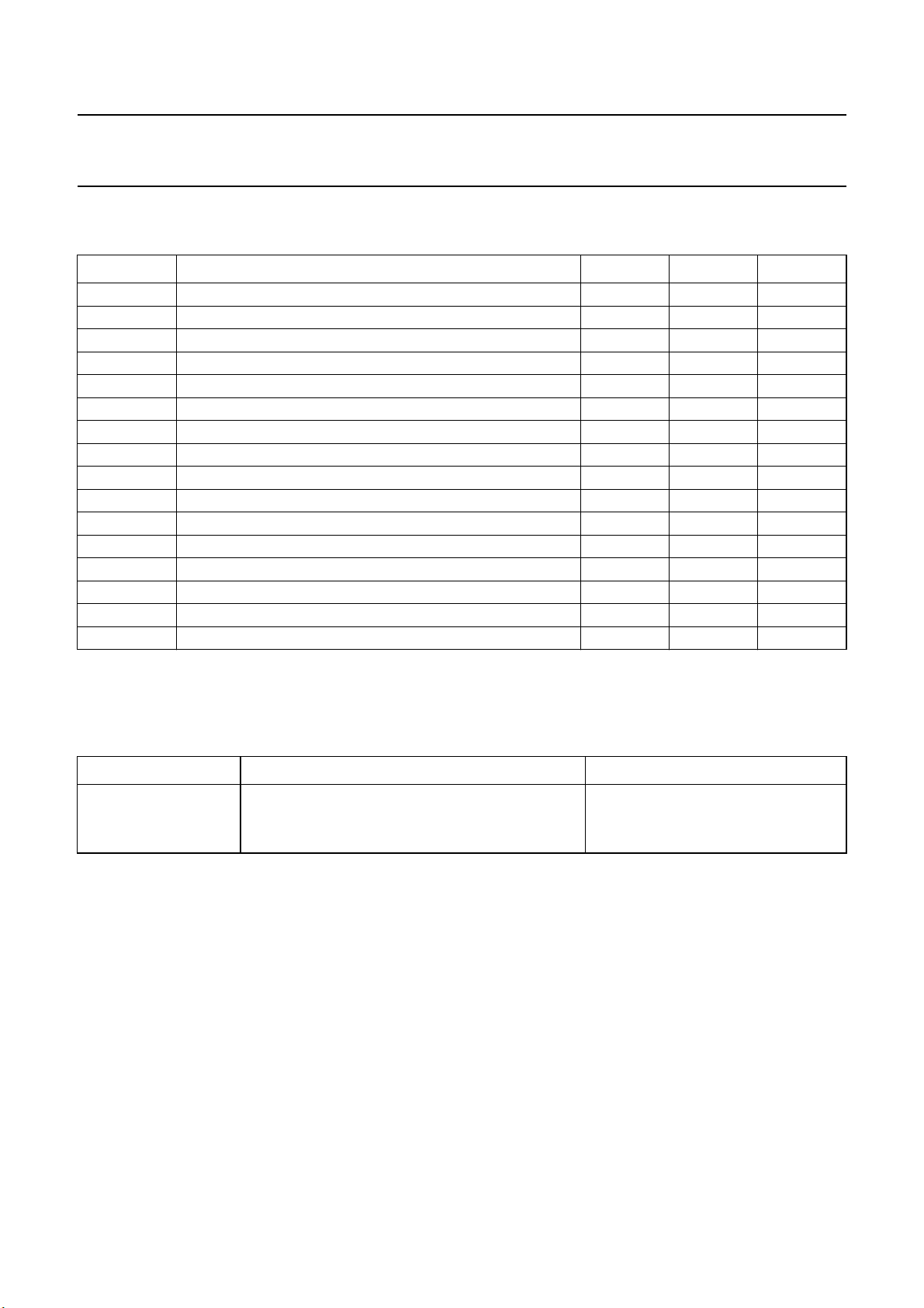
QUICK REFERENCE DATA
SYMBOL PARAMETER CONDITIONS MIN. TYP. MAX. UNIT
Supply
V
P2
I
P2
V
P1
I
P1
P
tot
supply voltage 4.5 5.0 5.5 V
supply current −−30 mA
supply voltage 7.2 8.0 8.8 V
supply current −−30 mA
total power
− 260 430 mW
dissipation
Inputs
V
20
input voltage RG=1kΩ− 12 V
Outputs
V
4
signal
identification
voltage
no signal;
−−0.3 V
1mA
signal open
− V
P1
V
collector
V
7
50/60 Hz
voltage
50 Hz; 1 mA −−0.3 V
60 Hz open
− V
P1
V
collector
V
10
vertical output
voltage
HIGH;
−1to0mA
2.7 − V
P2
V
LOW; 2 mA −−0.8 V
V
11
horizontal
output voltage
HIGH;
−1to0mA
2.7 − V
P2
V
LOW; 2 mA −−0.8 V
V
13
clock output
voltage
HIGH;
−1to0mA
2.7 − V
P2
V
LOW; 2 mA −−0.8 V
ORDERING INFORMATION
GENERAL DESCRIPTION
The TDA4691 is a bipolar integrated
EXTENDED
TYPE NUMBER
circuit for sync processing in 50/100
and 60/120 Hz TV sets, preferably in
conjunction with the programmable
deflection controller TDA9150. A line
locked 13.5 MHz clock with several
dividers and logic circuitry is available
generating the horizontal and vertical
sync outputs. The device can be
TDA4691 20 DIL plastic SOT146
TDA4691T 20 SO plastic SOT163
Note
1. SOT146-1; 1996 December 9.
2. SOT4163-1; 1996 December 9.
assembled in a DIL20 or SO20
package.
September 1993 2
PINS
PIN
POSITION
PACKAGE
MATERIAL CODE
(1)
(2)
This text is here in white to force landscape pages to be rotated correctly when browsing through the pdf in the Acrobat reader.This text is here in
_white to force landscape pages to be rotated correctly when browsing through the pdf in the Acrobat reader.This text is here inThis text is here in
white to force landscape pages to be rotated correctly when browsing through the pdf in the Acrobat reader. white to force landscape pages to be ...
September 1993 3
Philips Semiconductors Preliminary specification
Sync Processor with Clock (SPC) TDA4691
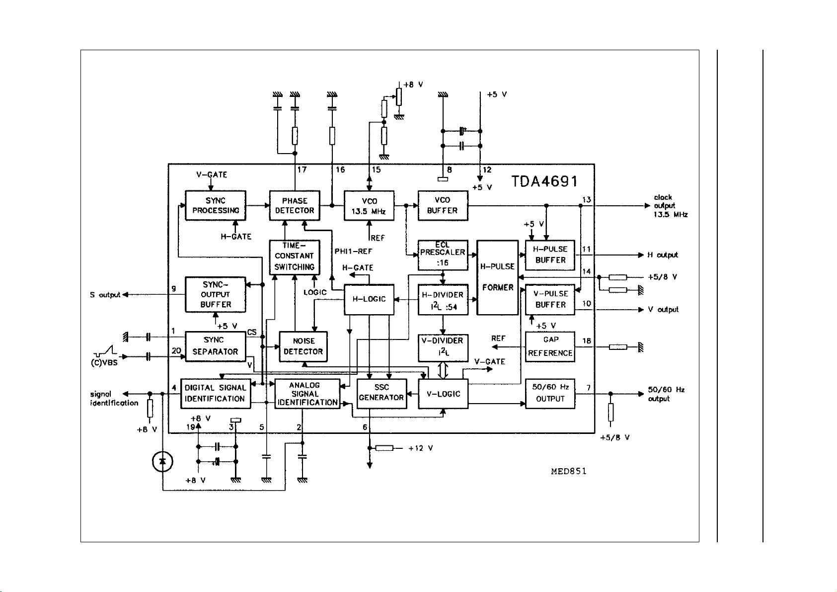
Fig.1 Block diagram.
Philips Semiconductors Preliminary specification
Sync Processor with Clock (SPC) TDA4691
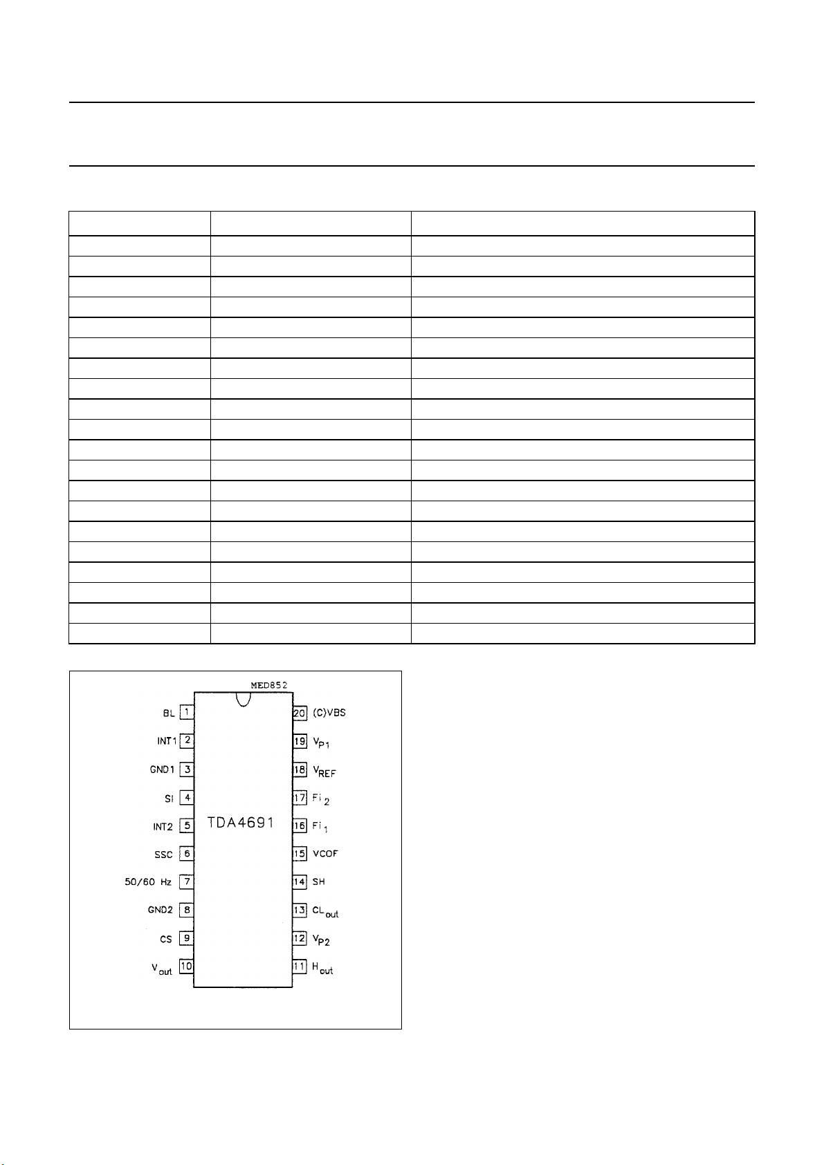
PINNING
SYMBOL PIN DESCRIPTION
BL 1 black level storage of sync separator
INT1 2 integration for time constant switching
GND1 3 ground for 8 V supply
SI 4 signal identification output
INT2 5 integration for signal identification
SSC 6 sandcastle output
50/60 Hz 7 50/60 Hz output
GND2 8 ground for 5 V supply
CS 9 sync output
V
out
H
out
V
P2
CL
out
SH 14 start of H-pulse
VCOF 15 current defining VCO frequency
Fi
1
Fi
2
V
REF
V
P1
(C)VBS 20 input sync separator
10 V-output buffer
11 H-output buffer
12 supply 5 V
13 clock-output buffer
16 phase detector filtering
17 phase detector filtering
18 reference voltage
19 supply 8 V
Fig.2 Pin configuration.
September 1993 4

Philips Semiconductors Preliminary specification
Sync Processor with Clock (SPC) TDA4691
FUNCTIONAL DESCRIPTION
(See block diagram Fig.1 and timing
Figs 12 to 16)
Sync separator
Top-sync and blacklevel are stored
and H and V sync pulses are sliced in
the middle of both levels (50%).
Sync-output buffer
This circuit turns the current pulse
from the sync separator into a TTL
signal.
Sync processing
This circuit assures that phase
comparison can operate correctly
during V-pulses. Phase jumps
initiated by alternating headpulses of
VCR recorders are quickly recovered.
The sync processing contains the
functions H/2 suppression, sync
extension and sync interruption.
These three functions are only active
if successive pulses have a minimum
distance of 1.6 µs.
The H/2 suppression operates with a
gate −15 µs up to +14 µs around the
PHI1-reference and is necessary for
suppression of the equalizing pulses.
For sync interruption this gate is
closed earlier if the detected sync is
longer than 4.8 µs.
Only during V-pulses will the duration
of the applied pulses be tested. If they
are longer than 1.6 µs they will be
recognized as sync pulses and
enlarged up to 4.6 µs.
Phase detector (PHI1)
The phase detector has separate
filters for the fast time constant T
(pin
1
17) and normal time constant T2 (pins
17 and 16). The slow time constant T
uses the normal time constant T2 with
reduced control current. For reduction
of H-pulse modulation the filter at pin
16 is switched off during sync time if
normal time constant T2 is on. Thus
no frequency shifting of the oscillator
is possible during sync.
Time-constant switching
This block contains a switch and an
impedance converter (buffer). The
switch connects the filters at pin 16
and 17 in parallel (normal time
constant T
or slow time constant T3).
2
The buffer transfers the control
voltage at pin 17 to pin 16 (fast time
constant T
). Which of the 2 functions
1
is active is determined by the blocks
noise detector, V-logic or signal
identification.
VCO 13.5 MHz
The adjustment of the nominal
frequency (13.5 MHz) is achieved at
pin 15. The VCO control voltage is
applied (from the phase detector) at
pin 16.
The control range can be adjusted by
the current at pin 18.
Pin 15 can be used to feed in an
external frequency. Under these
circumstances the internal VCO is
switched off by application.
The control voltage at pin 16 can be
used to control the external VCO.
VCO-buffer
The VCO-buffer delivers a TTL
compatible signal of 13.5 MHz to pin
13.
ECL-prescaler
This block consists of a :16
asynchronous prescaler.
H-divider
This is a divider by 54. It is split into a
prescaler :2 and a divider by 27. Out
of this block several signals are taken
3
for generation of H-frequently pulses
in the H-logic block. These signals
must have good timing. This is
achieved by special synchronization.
H-logic
This block creates all pulses
necessary for the SSC generator, the
signal identification, the phase
detector, the sync preparation and the
V-divider.
V-divider
The V-divider consists of an
asynchronous 10-bit divider and a
decoder logic. The divider is clocked
with twice the line frequency. The
decoder circuit delivers the pulses
necessary for the V-logic.
V-logic
In the V-logic the V-syncs from the
sync separator are evaluated and
noise reduced. Also certain operation
states are switched ON and OFF.
Additionally the reset pulse for the
V-divider and the 50/60 Hz
information is generated.
H-pulse former
The H-pulse starting point can be
shifted in this stage, also the gate
pulse of ∼2.4 µs is generated for use
in the digital noise identification block.
H-pulse buffer
In this circuit the line signal will be
pre-synchronized by output signal of
the :16 divider and synchronized by
the 13.5 MHz clock. The buffer
delivers TTL output signals.
V-pulse buffer
The signal out of the V-divider is
synchronized with 13.5 MHz clock
and converted to a TTL output level.
Gap reference
This circuit operates with the
gap-principle and is stable with regard
to temperature and supply voltage
changes.
September 1993 5

Philips Semiconductors Preliminary specification
Sync Processor with Clock (SPC) TDA4691
50/60 Hz output
This is an open-collector output,
which is LOW if more than 287
lines/field are detected.
SSC generator
The SSC generator generates a 3
stage super-sandcastle pulse on an
open-collector output, which is able to
operate up to 12 volts. The blanking
thresholds 2.5 V and 4.5 V are
derived from the gap reference (point
16).
Signal identification with Digital
PLL (DPLL)
The analog signal identification with
output signal at pin 4 is completed
with a DPLL. This PLL is able to lock
on the separated sync although the
13.5 MHz VCO is not locked on the
input signal. The ratio of the lock
condition to the unlock condition
influences the voltage at pin 5. The
detector circuit of the analog signal
identification block evaluates the
voltages at pins 2 and 5. If the voltage
at pin 5 reaches 4 V (most of the time
the PLL is locked) pin 4 will be HIGH.
The voltages at pins 2 and 5 together
with the state of the V-logic set the
operation state of the TDA4691. The
TDA4691 is able to accommodate to
different input conditions
automatically.
Some operation conditions can be
set externally by influencing the
voltages at pins 2 and 5:
1. Time constant T
voltage at pin 2 is limited to
5 V (0 to 5 V).
2. Time constant T3(slow) on:
voltage at pin 5 is limited to
6.2 V (0 to 6.2 V).
3. Time constant T3(slow)
inoperative:
voltage at pin 2 is limited
between 4 V and 6.5 V.
4. Time constant T3 (slow)
inoperative with input signal:
voltage at pin 2 is limited to
6.5 V (0 to 6.5 V).
5. VCO frequency fixed to f0:
pin 2 is set to ground
(V2< 1 V).
Noise detector
This block switches the time
constant to ‘slow’ if on standard
signal a certain noise level is
reached. This noise level is
measured in a small window
inside the sync pulse.
(fast) on:
1
September 1993 6
Philips Semiconductors Preliminary specification
Sync Processor with Clock (SPC) TDA4691
LIMITING VALUES
In accordance with the Absolute Maximum Rating System (IEC 134).
SYMBOL PARAMETER MIN. MAX. UNIT
V
I
V
I
P
T
T
V
I
V
V
V
V
V
V
V
P1
P1
P2
P2
tot
stg
amb
ESD
I/O
I
I
6
15
16
17
18
supply voltage 0 9.0 V
supply current − 40 mA
supply voltage 0 5.7 V
supply current − 50 mA
total power dissipation − 650 mW
storage temperature −25 +150 °C
operating ambient temperature 0 +70 °C
ESD-protection on all pins; note 1 300 − V
currents on all pins except supply pins 3, 8, 12 and 19 −10 +10 mA
voltage applied to pins 1, 2, 4, 5, 7, 14 and 20 0 V
voltage applied to pins 9, 10, 11 and 13 0 V
P1
P2
V
V
voltage applied to pin 6 0 13.2 V
voltage applied to pin 15 0 5 V
voltage applied to pin 16 0 5 V
voltage applied to pin 17 0 5 V
voltage applied to pin 18 0 5 V
Note to the limiting values
1. Equivalent to discharging a 200 pF capacitor through a 0 Ω series resistor.
THERMAL RESISTANCE
SYMBOL PARAMETER THERMAL RESISTANCE
R
th j-a
from junction to ambient in free air
SOT146 (without heat spreader) 65 K/W
SOT163 85 K/W
September 1993 7
Philips Semiconductors Preliminary specification
Sync Processor with Clock (SPC) TDA4691
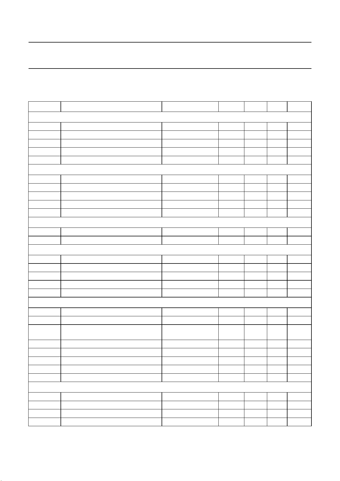
CHARACTERISTICS
V
=8V; VP2= 5 V; measured at T
P1
input signal referenced to CCIR standard.
SYMBOL PARAMETER CONDITIONS MIN. TYP. MAX. UNIT
Supply (pins 19 and 12; all voltages are measured with regard to ground (pins 3 and 8))
V
19
I
P1
V
12
I
P2
P
tot
supply voltage 7.2 8.0 8.8 V
supply current − 20 30 mA
supply voltage same rise time as V194.5 5.0 5.5 V
supply current − 15 30 mA
total power dissipation − 260 430 mW
Sync separator (pin 20)
V
20(p-p)
V
20(p-p)
R
G
I
20
I
20
input voltage (peak-to-peak value) AC coupled − 12V
sync amplitude (peak-to-peak value) 0.1 − 0.6 V
source resistor of generator −−1kΩ
current during sync −−30 −µA
current during remaining time − 1 −µA
Black level (pin 1)
SLH slicing level H − 50 − %
SLV slicing level V − 50 − %
= +25 °C; unless otherwise specified; application see Figs 10 and 11; video
amb
Sync output (pin 9)
V
9
V
9
C
L
t
1
t
2
no sync I9= +1mA − 0.3 − V
positive sync I9= −1 mA 2.7 − V
load capacitance −−40 pF
time delay between pin 20 and pin 9 see Fig.3 100 200 500 ns
time delay between pin 20 and pin 9 see Fig.3 100 300 500 ns
Phase detector (pins 16 and 17)
f
0
’f
f
0
I
17
nominal sync frequency − 15.625 − kHz
: 864 = phiref − 15.625 − kHz
osc
current at sync time
(fast and normal time constant)
I
17
I
16
V
17
V
16
∆f
/∆V
0
current at sync time (slow time constant) −±80 −µA
current at sync time time constant T
filter 2 voltage 1.5 3 4.5 V
filter 1 voltage 1.5 3 4.5 V
VCO sensitivity see VCO − 360 − kHz/V
16
13.5 MHz VCO (pin 15)
R
V
I
15
g
15
15
VCO
f0 defining resistor see Fig.4(a) − 3.75 − kΩ
pin voltage (V19 dependent) see Fig.4(a) 2.9 3 3.1 V
current for 13.5 MHz −720 −800 −880 µA
transconductance at f
V
12
−±240 −µA
1
0
−±2−mA
15.2 − 18.6 kHz/µA
September 1993 8
 Loading...