

Page 1

SureSigns VS2
Vital Signs Monitor
Release A.00
English
Service Guide
Page 2

Part Number 4535 641 31741
Printed in USA 1/09
First Edition
*453564131741*
Page 3

SureSigns VS2
Vital Signs Monitor
SERVICE GUIDE
Release A.00
English
Page 4

Notice
Proprietary Information
This document contains proprietary information, which is protected by copyright.
Copyright
Copyright © 2008 Koninklijke Philips Electronics N.V.
All Rights Reserved
Manufacturer
Philips Medical Systems
3000 Minuteman Road
Andover, MA 01810-1085
(978) 687-1501
Document Number
4535 641 31741
Warranty Disclaimer
The information contained in this document is subject to change without notice. Philips Medical
Systems makes no warranty of any kind with regard to this material, including, but not limited to, the
implied warranties or merchantability and fitness for a particular purpose. Philips Medical Systems
shall not be liable for errors contained herein or for incidental or consequential damages in connection
with the furnishing, performance, or use of this material.
ii
Page 5

Printing History
New editions of this document incorporate all material updated since the previous edition. Update
packages may be issued between editions and contain replacement and additional pages to be merged
by a revision date at the bottom of the page. Pages that are rearranged due to changes on a previous
page are not considered revised.
The documentation printing date and part number indicate its current edition. The printing date
changes when a new edition is printed. (Minor corrections and updates that are incorporated at reprint
do not cause the date to change.) The document part number changes when extensive technical
changes are incorporated.
First Edition . . . . . . . . . . . . . . . . . . . . . . . . . . . . . . . . . . . . . . . . . . . . . . . . . . . . . . . . . . . December 2008
Conventions
The manual uses the following conventions for Notes, Cautions, and Warnings.
Note — A Note calls attention to an important point in the text.
Caution A Caution calls attention to a condition or possible situation that could damage or destroy the
product or the user’s work.
Warning A Warning calls attention to a condition or possible situation that could cause injury to the user
and/or patient.
iii
Page 6
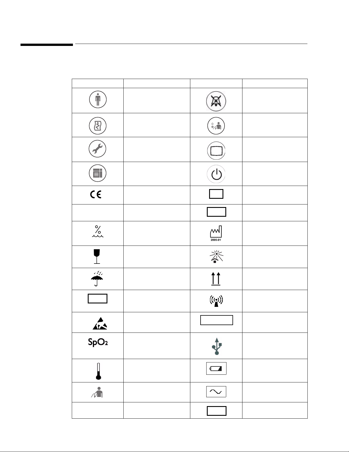
Explanation of Symbols
0123
SN
LOT
REF
STERILE
ICES-001
OPT
The following symbols appear on the monitor and its packaging.
Symbol Description Symbol Description
New Patient key Alarm Silence key
Print key NBP key
System Menu key Main Screen key
Display Mode key On/Standby key
CE marking Serial number
Rx Only Prescription Use Only
(US Federal Law)
Humidity Date of manufacture
Fragile, handle with care
Keep dry Keep Upright
Catalog number RF Interference
Electrostatic sensitive
device handling
connector USB port
SpO
2
Temperature connector Charging LED
Batch code
Keep out of sun
Sterile
NBP connector AC power LED
Canadian ISM
requirement
iv
Option number
Page 7
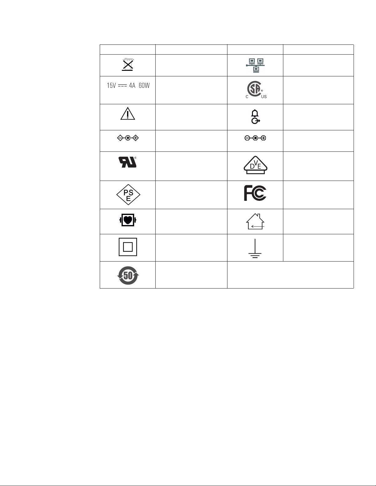
Symbol Description Symbol Description
Compliance with WEEE
standard
Power label CSA mark
Ethernet port
Caution, consult
Nurse call connector
accompanying documents
Polarity of DC power
connector (appears on
VS2 monitor)
UL Recognized
Polarity of DC power
connector (appears on
External Power Supply)
VDE Verification
Component
PSE marking FCC mark - USA
Defibrillator Proof Indoor use only
Class II Equipment Earth, ground
EUFP
(Environmentally-friendly
use period — China)
v
Page 8

Regulatory and Safety Specifications
0123
Declaration
The SureSigns VS2 vital signs monitor is a Class IIb device and complies with the requirements of the
Council Directive 93/42/EEC of 14 June 1993 concerning medical devices and carry CE-marking
accordingly.
Authorized EU Representative
Philips Medizin Systeme Böblingen GmbH
Hewlett-Packard Str. 2
71034 Böblingen
Germany
Rx Only
Caution United States Federal Law restricts this device to sale by or on the order of a physician.
Safety Standards
Parameter Specification
UL 60601-1, CAN/CSA C22.2 No. 601.1-M90, EN/IEC 60601-1, EN/IEC 60601-1-1 (as
applicable), EN/IEC60601-1-2, ISO 9919
Protection Class Class II, internally powered equipment, per IEC 60601-1
Degree of Protection Type CF defibrillator-proof: per IEC 60601-1
Mode of Operation Continuous
vi
Page 9

Contents
1 Introduction
Monitor Overview - - - - - - - - - - - - - - - - - - - - - - - - - - - - - - - - - - - - - - - 1-1
SureSigns VS2 Monitor Configurations - - - - - - - - - - - - - - - - - - - - - - - - - - - - - 1-2
Indications for Use - - - - - - - - - - - - - - - - - - - - - - - - - - - - - - - - - - - - - - - 1-2
Intended Use- - - - - - - - - - - - - - - - - - - - - - - - - - - - - - - - - - - - - - - - - - 1-2
Intended Audience - - - - - - - - - - - - - - - - - - - - - - - - - - - - - - - - - - - - - - - 1-2
2 Unpacking and Shipping
Overview - - - - - - - - - - - - - - - - - - - - - - - - - - - - - - - - - - - - - - - - - - - 2-1
Unpacking the Monitor - - - - - - - - - - - - - - - - - - - - - - - - - - - - - - - - - - - - - 2-1
Submitting a Damage Claim - - - - - - - - - - - - - - - - - - - - - - - - - - - 2-1
Returning the Monitor For Service - - - - - - - - - - - - - - - - - - - - - - - - - - - - - - - 2-2
Disposing of the Monitor- - - - - - - - - - - - - - - - - - - - - - - - - - - - - 2-3
3 Performing Routine Maintenance
Recommended Frequency - - - - - - - - - - - - - - - - - - - - - - - - - - - - - - - - - - - 3-1
Routine Safety and Operational Checks - - - - - - - - - - - - - - - - - - - - - - - - - - - - - 3-1
Cleaning and Disinfecting - - - - - - - - - - - - - - - - - - - - - - - - - - - - - - - - - - - 3-2
General Guidelines - - - - - - - - - - - - - - - - - - - - - - - - - - - - - - - 3-2
Cleaning and Disinfecting the Monitor - - - - - - - - - - - - - - - - - - - - - - 3-2
Cleaning and Disinfecting the Cables and External Power Supply - - - - - - - - - 3-3
Cleaning the Barcode Scanner - - - - - - - - - - - - - - - - - - - - - - - - - - 3-4
Maintaining the Battery- - - - - - - - - - - - - - - - - - - - - - - - - - - - - - - - - - - - - 3-4
About the Battery - - - - - - - - - - - - - - - - - - - - - - - - - - - - - - - - 3-4
Battery Status Indicators - - - - - - - - - - - - - - - - - - - - - - - - - - - - - 3-5
Charging the Battery - - - - - - - - - - - - - - - - - - - - - - - - - - - - - - - 3-5
Reconditioning the Battery - - - - - - - - - - - - - - - - - - - - - - - - - - - - 3-5
Replacing the Battery - - - - - - - - - - - - - - - - - - - - - - - - - - - - - - 3-6
Battery Messages and Alarms - - - - - - - - - - - - - - - - - - - - - - - - - - 3-6
Technical Alarms- - - - - - - - - - - - - - - - - - - - - - - - - - - - - - 3-6
Error Codes - - - - - - - - - - - - - - - - - - - - - - - - - - - - - - - - 3-6
4 Configuring the Monitor
Accessing the System Menu - - - - - - - - - - - - - - - - - - - - - - - - - - - - - - - - - - 4-1
Accessing the System Admin Menu - - - - - - - - - - - - - - - - - - - - - - - - - - - - - - - 4-1
System Admin Menu Options - - - - - - - - - - - - - - - - - - - - - - - - - - 4-3
Setting Auto Suspend- - - - - - - - - - - - - - - - - - - - - - - - - - - - - - - - - - - - - - 4-5
Setting Auto Save Patient Record - - - - - - - - - - - - - - - - - - - - - - - - - - - - - - - - 4-5
VS2 Vital Signs Monitor Service Guide
Contents-1
Page 10

Configuring the Default Alarm Settings - - - - - - - - - - - - - - - - - - - - - - - - - - - - - -4-6
Accessing the Default Alarm Settings Menu- - - - - - - - - - - - - - - - - - - - -4-6
Setting the Alarm Tone Pattern - - - - - - - - - - - - - - - - - - - - - - - - - - -4-8
Setting the Alarm Pause Duration- - - - - - - - - - - - - - - - - - - - - - - - - -4-8
Setting the Minimum Nurse Call Alarm Priority - - - - - - - - - - - - - - - - - - -4-9
Setting the Minimum Alarm Tone Volume - - - - - - - - - - - - - - - - - - - - -4-9
Changing the Default Alarm Settings - - - - - - - - - - - - - - - - - - - - - - - 4-10
Factory Default Alarm Limits - - - - - - - - - - - - - - - - - - - - - - - - 4-10
Restricting Alarm and Audio Settings- - - - - - - - - - - - - - - - - - - - - - - 4-11
Latching Physiological Alarms - - - - - - - - - - - - - - - - - - - - - - - - - - 4-11
Configuring the Service Settings - - - - - - - - - - - - - - - - - - - - - - - - - - - - - - - - 4-12
Accessing the Service Menu - - - - - - - - - - - - - - - - - - - - - - - - - - - 4-12
Selecting a Language - - - - - - - - - - - - - - - - - - - - - - - - - - - - - - 4-14
Exporting Configuration Settings - - - - - - - - - - - - - - - - - - - - - - - - - 4-14
Upgrading the Software - - - - - - - - - - - - - - - - - - - - - - - - - - - - - 4-15
Importing Configuration Settings - - - - - - - - - - - - - - - - - - - - - - - - - 4-17
Configuring the Patient Identification Settings - - - - - - - - - - - - - - - - - - - - - - - - - - 4-17
Changing the Patient ID Settings - - - - - - - - - - - - - - - - - - - - - - - - - 4-17
Configuring the Default Initial NBP Inflation Pressure - - - - - - - - - - - - - - - - - - - - - - 4-19
Setting Demo Mode - - - - - - - - - - - - - - - - - - - - - - - - - - - - - - - - - - - - - - 4-20
Clearing Patient Data- - - - - - - - - - - - - - - - - - - - - - - - - - - - - - - - - - - - - - 4-20
Installing the Power Cord Retainer Clip - - - - - - - - - - - - - - - - - - - - - - - - - - - - - 4-22
Installing the USB Hub - - - - - - - - - - - - - - - - - - - - - - - - - - - - - - - - - - - - - 4-23
Installing the RS-232 Serial Interface Adapter - - - - - - - - - - - - - - - - - - - - - - - - - - 4-24
Removing the Insulator Sheath - - - - - - - - - - - - - - - - - - - - - - - - - - 4-26
5 Performance Verification Testing
Overview - - - - - - - - - - - - - - - - - - - - - - - - - - - - - - - - - - - - - - - - - - - -5-1
Testing and Inspection Guidelines- - - - - - - - - - - - - - - - - - - - - - - - - - - - - - - - -5-1
Recommended Frequency - - - - - - - - - - - - - - - - - - - - - - - - - - - - - - - - - - - -5-2
Required Test Equipment- - - - - - - - - - - - - - - - - - - - - - - - - - - - - - - - - - - - -5-2
Test Recording- - - - - - - - - - - - - - - - - - - - - - - - - - - - - - - - - - - - - - - - - -5-3
Performing Verification Tests- - - - - - - - - - - - - - - - - - - - - - - - - - - - - - - - - - -5-3
Visual Test - - - - - - - - - - - - - - - - - - - - - - - - - - - - - - - - - - - - - - - - - - -5-6
Power-On Self Test - - - - - - - - - - - - - - - - - - - - - - - - - - - - - - - - - - - - - - -5-7
Alarms Test - - - - - - - - - - - - - - - - - - - - - - - - - - - - - - - - - - - - - - - - - - -5-7
SpO
Test - - - - - - - - - - - - - - - - - - - - - - - - - - - - - - - - - - - - - - - - - - - -5-8
2
NBP Test - - - - - - - - - - - - - - - - - - - - - - - - - - - - - - - - - - - - - - - - - - - -5-9
NBP Accuracy- - - - - - - - - - - - - - - - - - - - - - - - - - - - - - - - - - -5-9
NBP Calibration Procedure- - - - - - - - - - - - - - - - - - - - - - - - - - - - 5-11
Pneumatic Leakage Test - - - - - - - - - - - - - - - - - - - - - - - - - - - - - 5-12
NBP Overpressure Valve Test - - - - - - - - - - - - - - - - - - - - - - - - - - 5-12
Temperature Test - - - - - - - - - - - - - - - - - - - - - - - - - - - - - - - - - - - - - - - 5-13
Safety Test- - - - - - - - - - - - - - - - - - - - - - - - - - - - - - - - - - - - - - - - - - - 5-14
Patient Leakage Current with Mains Voltage - - - - - - - - - - - - - - - - - - - 5-14
Expected Test Results - - - - - - - - - - - - - - - - - - - - - - - - - - - 5-14
Nurse Call Relay Test - - - - - - - - - - - - - - - - - - - - - - - - - - - - - - - - - - - - - 5-15
Barcode Scanner Test - - - - - - - - - - - - - - - - - - - - - - - - - - - - - - - - - - - - - 5-16
Contents-2
VS2 Vital Signs Monitor Service Guide
Page 11

6 Troubleshooting
Overview - - - - - - - - - - - - - - - - - - - - - - - - - - - - - - - - - - - - - - - - - - - 6-1
When You Cannot Correct a Problem - - - - - - - - - - - - - - - - - - - - - - - 6-1
Viewing System Information - - - - - - - - - - - - - - - - - - - - - - - - - - - - - - - - - - 6-2
Diagnosing a Problem - - - - - - - - - - - - - - - - - - - - - - - - - - - - - - - - - - - - - 6-3
Boot and Power Sequences - - - - - - - - - - - - - - - - - - - - - - - - - - - - - - - - - - - 6-4
Troubleshooting Tables - - - - - - - - - - - - - - - - - - - - - - - - - - - - - - - - - - - - - 6-5
Power Problems - - - - - - - - - - - - - - - - - - - - - - - - - - - - - - - - - 6-6
Display Problems - - - - - - - - - - - - - - - - - - - - - - - - - - - - - - - - 6-8
Alarm Problems - - - - - - - - - - - - - - - - - - - - - - - - - - - - - - - - - 6-8
NBP Problems - - - - - - - - - - - - - - - - - - - - - - - - - - - - - - - - - - 6-9
Temperature Measurement Problems - - - - - - - - - - - - - - - - - - - - - - 6-10
SpO
Measurement Problems- - - - - - - - - - - - - - - - - - - - - - - - - - - 6-11
2
Navigation Wheel and Key Problems- - - - - - - - - - - - - - - - - - - - - - - 6-11
Recorder Problems- - - - - - - - - - - - - - - - - - - - - - - - - - - - - - - - 6-12
Barcode Scanner Problems - - - - - - - - - - - - - - - - - - - - - - - - - - - - 6-12
Resetting the Barcode Scanner - - - - - - - - - - - - - - - - - - - - - - - - - - - - - - - - - 6-13
Error Codes - - - - - - - - - - - - - - - - - - - - - - - - - - - - - - - - - - - - - - - - - - 6-14
Running System Diagnostics - - - - - - - - - - - - - - - - - - - - - - - - - - - - - - - - - - 6-25
Maintenance Options- - - - - - - - - - - - - - - - - - - - - - - - - - - - - - - 6-26
Running the Self Test- - - - - - - - - - - - - - - - - - - - - - - - - - - - - - - - - - - - - - 6-27
Testing the Speaker- - - - - - - - - - - - - - - - - - - - - - - - - - - - - - - - - - - - - - - 6-28
Testing the Navigation Wheel and Keys - - - - - - - - - - - - - - - - - - - - - - - - - - - - - 6-28
Testing the Display - - - - - - - - - - - - - - - - - - - - - - - - - - - - - - - - - - - - - - - 6-29
Viewing the Battery Information - - - - - - - - - - - - - - - - - - - - - - - - - - - - - - - - 6-30
Testing the Optional Recorder- - - - - - - - - - - - - - - - - - - - - - - - - - - - - - - - - - 6-31
Testing the LED - - - - - - - - - - - - - - - - - - - - - - - - - - - - - - - - - - - - - - - - 6-31
Viewing and Resetting Tracked Parameters - - - - - - - - - - - - - - - - - - - - - - - - - - - 6-32
Resetting Parameters - - - - - - - - - - - - - - - - - - - - - - - - - - - - - - - 6-32
Viewing and Printing the Error Log - - - - - - - - - - - - - - - - - - - - - - - - - - - - - - - 6-33
7 Repairing the Monitor
Disassembling the Monitor - - - - - - - - - - - - - - - - - - - - - - - - - - - - - - - - - - - 7-1
Tools Required for Service - - - - - - - - - - - - - - - - - - - - - - - - - - - - - - - - - - - 7-2
Replacing the Battery- - - - - - - - - - - - - - - - - - - - - - - - - - - - - - - - - - - - - - 7-2
Performing a Hard Shutdown - - - - - - - - - - - - - - - - - - - - - - - - - - - 7-2
Removing the Battery - - - - - - - - - - - - - - - - - - - - - - - - - - - - - - 7-3
Installing the Battery - - - - - - - - - - - - - - - - - - - - - - - - - - - - - - - 7-4
Removing the Temperature Module - - - - - - - - - - - - - - - - - - - - - - - - - - - - - - - 7-5
Replacing the Temperature Adapter Board- - - - - - - - - - - - - - - - - - - - - - - - - - - - 7-7
Removing the Recorder Faceplate - - - - - - - - - - - - - - - - - - - - - - - - - - - - - - - - 7-8
Removing the Optional Recorder - - - - - - - - - - - - - - - - - - - - - - - - - - - - - - - - 7-9
Removing the Rear Case - - - - - - - - - - - - - - - - - - - - - - - - - - - - - - - - - - - - 7-10
Reassembling the Monitor - - - - - - - - - - - - - - - - - - - - - - - - - - - - 7-13
Removing the Main Chassis Assembly - - - - - - - - - - - - - - - - - - - - - - - - - - - - - 7-13
Reassembling the Main Chassis Assembly - - - - - - - - - - - - - - - - - - - - 7-14
Removing the Speaker - - - - - - - - - - - - - - - - - - - - - - - - - - - - - - - - - - - - - 7-15
VS2 Vital Signs Monitor Service Guide
Contents-3
Page 12

Replacing the Handle O-Ring - - - - - - - - - - - - - - - - - - - - - - - - - - - - - - - - - - 7-16
Removing the Connector Panel Assembly - - - - - - - - - - - - - - - - - - - - - - - - - - - - 7-16
Removing the Connector Blocks - - - - - - - - - - - - - - - - - - - - - - - - - 7-18
Removing the SpO
Removing the SpO
Board - - - - - - - - - - - - - - - - - - - - - - - - - - - - - - - - - - - 7-19
2
Adapter Board - - - - - - - - - - - - - - - - - - - - - - - - - - - - - - - 7-20
2
Removing the Daughter Board - - - - - - - - - - - - - - - - - - - - - - - - - - - - - - - - - 7-21
Removing the NBP Module- - - - - - - - - - - - - - - - - - - - - - - - - - - - - - - - - - - 7-24
Removing the NBP Filter - - - - - - - - - - - - - - - - - - - - - - - - - - - - - - - - - - - - 7-26
Removing the Battery Connector Board - - - - - - - - - - - - - - - - - - - - - - - - - - - - - 7-26
Removing the Navigation Wheel Assembly - - - - - - - - - - - - - - - - - - - - - - - - - - - 7-28
Removing the Main Board - - - - - - - - - - - - - - - - - - - - - - - - - - - - - - - - - - - 7-30
Resetting the Serial Number - - - - - - - - - - - - - - - - - - - - - - - - - - - 7-32
Setting the System Configuration - - - - - - - - - - - - - - - - - - - - - - - - - 7-34
Removing the LCD - - - - - - - - - - - - - - - - - - - - - - - - - - - - - - - - - - - - - - 7-36
8 Replacement Parts and Assembly Drawings
Spare Parts- - - - - - - - - - - - - - - - - - - - - - - - - - - - - - - - - - - - - - - - - - - -8-1
Assembly Drawings - - - - - - - - - - - - - - - - - - - - - - - - - - - - - - - - - - - - - - -8-3
Power Supply Cords - - - - - - - - - - - - - - - - - - - - - - - - - - - - - - - - - - - - - - -8-5
A Theory of Operation
Overview - - - - - - - - - - - - - - - - - - - - - - - - - - - - - - - - - - - - - - - - - - - A-1
Block Diagram Components - - - - - - - - - - - - - - - - - - - - - - - - - - - - - - - - - - A-1
Block Diagram - - - - - - - - - - - - - - - - - - - - - - - - - - - - - - - - - A-2
Main PCB - - - - - - - - - - - - - - - - - - - - - - - - - - - - - - - - - - - - A-3
Daughter PCB - - - - - - - - - - - - - - - - - - - - - - - - - - - - - - - - - - A-3
NBP Assembly and Circuitry - - - - - - - - - - - - - - - - - - - - - - - - A-3
Power Management - - - - - - - - - - - - - - - - - - - - - - - - - - - - A-4
Speaker - - - - - - - - - - - - - - - - - - - - - - - - - - - - - - - - - - A-4
Nurse Call Contacts - - - - - - - - - - - - - - - - - - - - - - - - - - - - A-4
SpO
Adapter PCB - - - - - - - - - - - - - - - - - - - - - - - - - - - - - - - A-4
2
Temperature Adapter PCB - - - - - - - - - - - - - - - - - - - - - - - - - - - - A-5
Front Panel Assembly - - - - - - - - - - - - - - - - - - - - - - - - - - - - - - A-5
Navigation Wheel - - - - - - - - - - - - - - - - - - - - - - - - - - - - - A-5
Power Supply Module - - - - - - - - - - - - - - - - - - - - - - - - - - - - - - A-5
Recorder - - - - - - - - - - - - - - - - - - - - - - - - - - - - - - - - - - - - A-5
SpO
Module - - - - - - - - - - - - - - - - - - - - - - - - - - - - - - - - - - A-6
2
Temperature- - - - - - - - - - - - - - - - - - - - - - - - - - - - - - - - - - - A-6
Predictive Measurements - - - - - - - - - - - - - - - - - - - - - - - - - - A-6
Monitored Measurements - - - - - - - - - - - - - - - - - - - - - - - - - - A-6
B Electromagnetic Compatibility
Index
Contents-4
VS2 Vital Signs Monitor Service Guide
Page 13
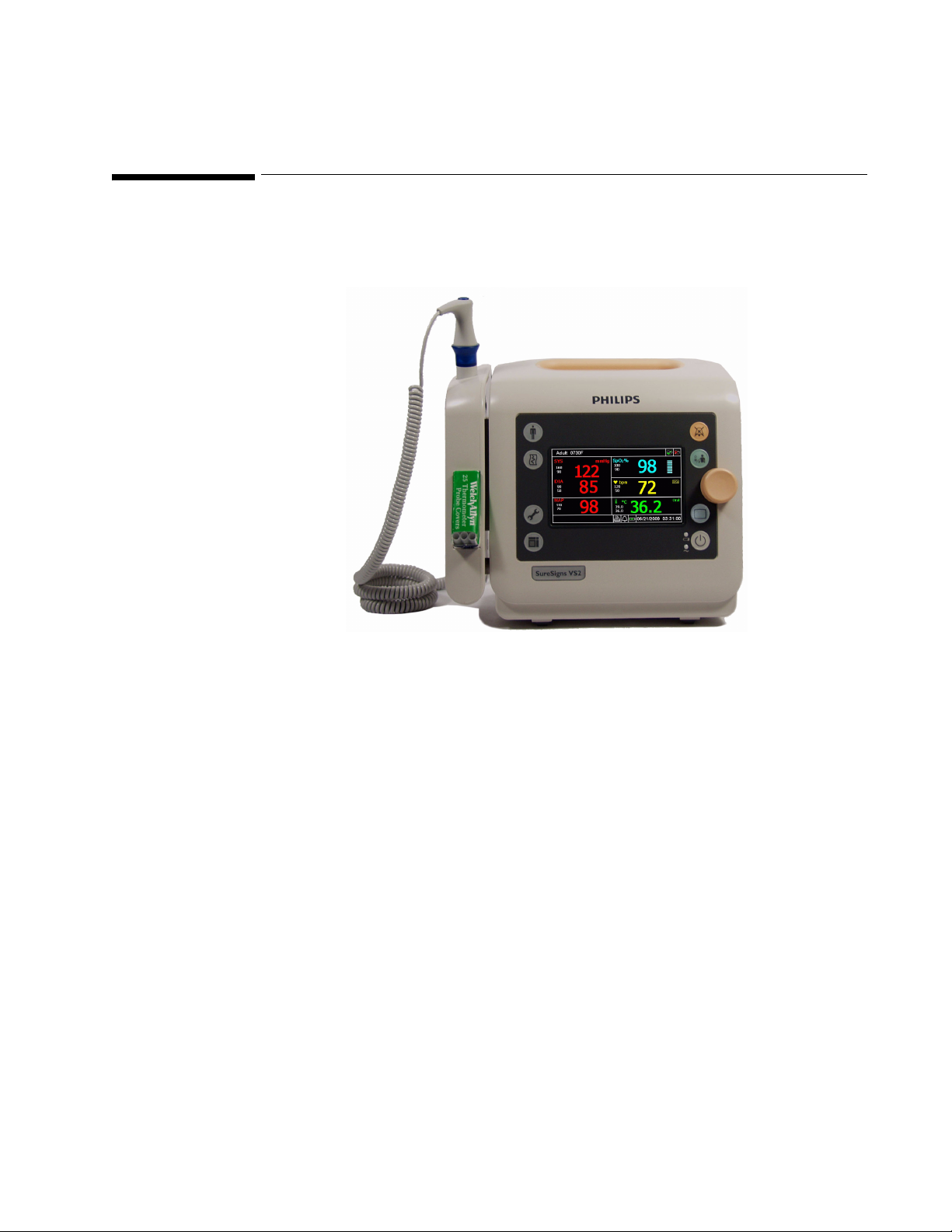
Monitor Overview
The SureSigns™ VS2 vital signs monitor is easy to use and versatile. The monitor is available in
several configurations and with optional features to best suit your needs.
1
Introduction
The SureSigns VS2 is a vital signs monitor that measures blood pressure, pulse rate, oxygen saturation
(SpO
), and temperature. Features include:
2
• Adult, pediatric, and neonatal capability
• Lithium ion battery
• Stores up to 100 patient records
• Optional recorder
• Optional roll stand or wall mount
• Optional barcode scanner for Patient ID entry
• LAN and serial data export
• Optional wireless network connection to EMR
Introduction
SureSigns VS2 Vital Signs Monitor Service Guide 1-1
Page 14

SureSigns VS2 Monitor Configurations
SureSigns VS2 Monitor Configurations
The SureSigns VS2 vital signs monitor is available in the configurations shown in the following table.
Model
863079
863080
863081
863082
Indications for Use
The SureSigns VS2 vital signs monitor is for use by health care professionals whenever there is a need for
monitoring the physiological parameters of patients.
Intended Use
Measurement Parameters and Features
NBP SpO
YesNoNoNo
Yes Yes No No
YesYesYesNo
YesYesYesYes
2
Temperature Recorder
The SureSigns VS2 vital signs monitor is for monitoring, recording and alarming of multiple
physiological parameters of adults, pediatrics, and neonates in healthcare environments. Additionally, the
monitor is intended for use in transport situations within a healthcare facility.
Intended Audience
This guide is for biomedical engineers or technicians responsible for troubleshooting, repairing, and
maintaining Philips patient monitoring systems.
Introduction
1-2 SureSigns VS2 Vital Signs Monitor Service Guide
Page 15

Overview
This chapter describes how to:
• Unpack the monitor
• Return the monitor
• Dispose of the monitor
Unpacking the Monitor
To unpack the monitor:
Step
2
Unpacking and Shipping
1 Open the shipping container and remove the monitor from the container.
2 Examine the monitor for visible damage, like broken components, cables,
dents, or scratches on the surface of the equipment.
3 Store all documentation in an appropriate location
4 Save the packaging material for possible reuse.
Submitting a Damage Claim
If there is physical damage, or if an item does not meet specified operational requirements, notify the
carrier and the nearest Philips Medical Systems sales/service office. Philips will arrange for immediate
repair or replacement of the damaged/inoperative part.
Unpacking and Shipping
SureSigns VS2 Vital Signs Monitor Service Guide 2-1
Page 16
Returning the Monitor For Service
Returning the Monitor For Service
To return the monitor for service, call the Philips Customer Care Center or your local Philips
representative for a Returned Materials Authorization (RMA) number. Have all equipment serial numbers
available when calling. Mark the shipping carton and any shipping documents with the RMA number.
Warning Before returning any equipment to Philips:
• Back up the configuration (see “Exporting Configuration Settings” on page 4-14).
• Clean and disinfect it (see “Cleaning and Disinfecting” on page 3-2).
• Delete all patient data (see “Clearing Patient Data” on page 4-20).
• Remove the battery (see “Replacing the Battery” on page 7-2).
• If your monitor is equipped with a wireless assembly, remove all of the wireless components (see
the SureSigns VS2 Wireless Installation and Setup Guide).
To pack the monitor for return, disconnect all cables. It is not necessary to return accessories or the
external power supply. If available, use the original carton and packing materials.
Ensure that the monitor is transported within the following specifications:
• Temperature: -20°C to +40°C (-4°F to 104°F)
• Humidity: 15% to 90%
• Atmospheric Pressure: 708 hPa to 1014 hPa
To return the monitor in the original packaging:
Step
1 Place the monitor in the original packaging.
2 Seal the carton with packaging tape.
3 Label the carton with the shipping address, return address, and RMA number.
If the original carton is not available, use the following procedure to pack the monitor:
Step
1 Place the monitor in a plastic bag.
2 Locate a corrugated cardboard shipping carton with at least 200 psi (pounds per
square inch) bursting strength.
3 Fill the bottom of the carton with at least 2 inches of packing material.
4 Place the bagged unit on the layer of packing material and fill the box
completely with packing material.
5 Seal the carton with packaging tape.
6 Label the carton with the shipping address, return address, and RMA number.
Unpacking and Shipping
2-2 SureSigns VS2 Vital Signs Monitor Service Guide
Page 17

Disposing of the Monitor
To avoid contaminating or infecting personnel, the environment, or other equipment, make sure that you
disinfect and decontaminate the monitor appropriately before disposing of it in accordance with your
country’s law for equipment containing electrical and electronic parts.
For disposal of parts and accessories, where not otherwise specified, follow local regulations regarding
disposal of hospital waste.
Note — Before disposing of a SureSigns VS2 monitor, delete all patient information. To delete patient
data from the monitor, see “Clearing Patient Data” on page 4-20.
Returning the Monitor For Service
Unpacking and Shipping
SureSigns VS2 Vital Signs Monitor Service Guide 2-3
Page 18

Returning the Monitor For Service
Unpacking and Shipping
2-4 SureSigns VS2 Vital Signs Monitor Service Guide
Page 19

Performing Routine Maintenance
Recommended Frequency
Perform the maintenance procedures at the recommended frequency shown in the following table.
Caution The frequency recommendations in the following table do not supersede local requirements.
Always perform locally required testing in addition to the testing outlined here.
Maintenance Procedure Frequency
Routine Safety and Operational Checks
• Visual Inspection of exterior for damage Before use
• Inspection of labels for legibility Before use
Cleaning and Disinfecting According to your institution’s policy or between
each patient
3
Battery
• Charging As needed
• Reconditioning Every six months
Routine Safety and Operational Checks
Philips recommends that you regularly:
• Visually inspect the monitor exterior for damage.
• Inspect the monitor labels for legibility.
If the labels are not legible, contact the Philips Customer Care Center or your local Philips
representative.
Philips recommends that you perform certain test and verification checks at least once a year and after
each repair. For complete information on performing verification testing and checks, see
Chapter 5, “Performance Verification Testing.”
Performing Routine Maintenance
SureSigns VS2 Vital Signs Monitor Service Guide 3-1
Page 20

Cleaning and Disinfecting
Cleaning and Disinfecting
To clean or disinfect your SureSigns VS2 vital signs monitor, use only the approved cleaning agents
listed in this chapter.
Warning Do not use unapproved cleaning or disinfecting agents. Even small quantities of some cleaning
agents will damage the monitor or external power supply.
Do not use abrasive cleaners or strong solvents such as acetone or acetone-based compounds. The
warranty does not cover damage caused by using unapproved substances.
General Guidelines
Keep the monitor, cables, external power supply, and accessories free of dust and dirt. After cleaning and
disinfecting, check the equipment carefully. Do not use the monitor if you see signs of deterioration or
damage.
If you need to return any equipment to Philips, clean and disinfect it first.
Follow these general precautions:
• Always dilute cleaning agents according to the manufacturer’s instructions or use the lowest
possible concentration.
• Do not allow liquid to enter the case.
• Do not immerse any part of the equipment in liquid.
• Do not pour liquid onto the system.
• Never use abrasive material (such as steel wool or silver polish).
• Do not autoclave, steam sterilize, or ultrasonically clean the monitor or cables.
• Do not use bleach on electrical contacts or connectors.
• Do not use alcohol on the patient cables. Alcohol can cause the plastic to become brittle and fail
prematurely.
Caution If you spill liquid on the exterior of the monitor or external power supply, use a clean cloth to dry
them. If you believe the liquid may have gotten inside the monitor or external power supply, contact
your biomedical engineer, who can verify the performance and safety of the equipment.
Cleaning and Disinfecting the Monitor
To clean the monitor:
Step
1 Dampen a soft cloth with mild soap and water.
2 Wring any excess moisture from the cloth and gently clean the monitor.
Performing Routine Maintenance
3-2 SureSigns VS2 Vital Signs Monitor Service Guide
Page 21

Cleaning and Disinfecting
To disinfect the monitor:
Step
1 Dampen a soft cloth with any of the following:
• Isopropyl alcohol (70% solution in water)
• Sodium hypochlorite (chlorine bleach), 3% solution in water
• Ammonium chloride solution, <0.2% solution
2 Wring any excess moisture from the cloth and wipe the monitor to disinfect it.
Cleaning and Disinfecting the Cables and External Power Supply
Caution Do not use alcohol to clean the cables. Alcohol can cause the cables to become brittle.
To clean the cables and external power supply:
Step
1 Dampen a soft cloth with alcohol-free hand soap.
2 Wring any excess moisture from the cloth and gently clean the cables and
external power supply.
3 Clean the areas again with damp cloth moistened with water only.
To disinfect the cables and external power supply:
Step
1 Dampen a soft cloth with sodium hypochlorite (chlorine bleach), 3% solution in
water.
Caution: Sodium hypochlorite may discolor the cable.
2 Wring any excess moisture from the cloth and gently clean the cables.
3 Clean the areas again with damp cloth moistened with water only.
Performing Routine Maintenance
SureSigns VS2 Vital Signs Monitor Service Guide 3-3
Page 22

Maintaining the Battery
Cleaning the Barcode Scanner
To clean the scanner:
Step
1 Disconnect the scanner from the monitor.
2 Dampen a soft cloth with water (or a mild detergent-water solution). Wring any
excess moisture from the cloth.
3 Wipe the surfaces of the scanner.
If a detergent solution is used, rinse the scanner with a soft cloth dampened
with water only.
Reading performance may degrade if the barcode scanner’s window is not clean. If the window is visibly
dirty, or if the scanner isn’t operating well:
Step
1 Dampen a soft cloth or lens tissue with water (or a mild detergent-water
solution). Wring any excess moisture from the cloth.
2 Clean the window.
If a detergent solution is used, rinse the window with a soft cloth dampened
with water only.
Caution Do not submerge the barcode scanner in water. Do not use abrasive wipes or tissues on the
scanner’s window — abrasive wipes may scratch the window. Never use solvents (for example,
acetone, benzene, ether, or phenol-based agents) on the housing or window. Solvents may damage
the finish or the window.
Maintaining the Battery
About the Battery
The rechargeable lithium ion battery used in the monitor is a smart battery with built-in circuitry that
communicates battery status information to the monitor. Battery power lasts a minimum of four hours of
continuous monitoring with no printing and one NBP measurement every 15 minutes.
Observe these guidelines:
• If a battery shows damage or signs of leakage, replace it immediately.
• Never use a faulty battery in the monitor.
• Never dispose of the battery in a normal waste container.
• Never leave a battery inside the monitor if it is not used for a long period of time.
• Never store a battery that is more than 50% charged.
Performing Routine Maintenance
3-4 SureSigns VS2 Vital Signs Monitor Service Guide
Page 23
Battery Status Indicators
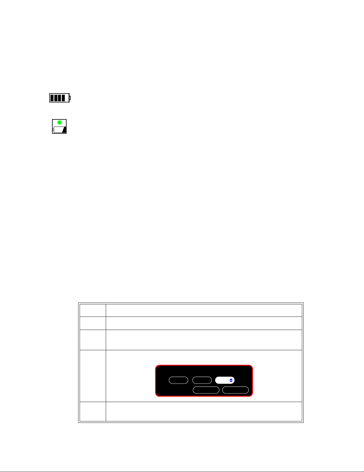
Battery Status
Charging LED
OK
Please enter the password:
512
Cancel
You can check the status of the battery (level of charge) by using:
• The Battery Status pane
• The Charging LED
• Battery messages and alarms (see “Battery Messages and Alarms” on page 3-6).
The Battery Status pane at the bottom of the main screen indicates the remaining charge in the battery.
The color of the Charging LED on the front panel indicates how much charge remains on the battery:
• Green: The battery is at least 90% charged.
• Flashing Green: More than 30% charge, but less than 90%.
• Yellow: More than 21% charge, but less than 30%.
• Flashing Yellow: More than 12% charge, but less than 21% charge.
• Off: The monitor is in Deep Sleep, the battery has less than 12% charge, or the battery is removed.
Charging the Battery
When the monitor is connected to AC power, the battery begins charging.
When you first receive the monitor, the battery charge may be low. Connect the monitor to an AC power
source before using it on battery power alone.
You can recharge the battery while the monitor is in use. If the monitor is not in use, a complete battery
recharge requires less than four hours.
Maintaining the Battery
Reconditioning the Battery
Each time the battery is charged, its capacity decreases slightly. Therefore, the operating time the monitor
can run on battery power decreases slightly with each charge cycle. Battery reconditioning recalibrates
the battery to ensure that the value stored in the battery for its full capacity takes this decrease in capacity
into account and allows the remaining battery charge to be calculated accurately.
Philips recommends that you condition the battery by fully discharging and recharging it every six
months.
Step
1 Press the System Menu key.
2In the
3 In the window that appears, enter the Administrator password,
4In the
System Menu, rotate the wheel to System Admin, and then press the
wheel.
System Admin Menu, rotate the wheel to Service, and then press the
wheel.
2-1-5, as shown:
Performing Routine Maintenance
SureSigns VS2 Vital Signs Monitor Service Guide 3-5
Page 24

Maintaining the Battery
5In the
wheel.
6 Rotate the wheel to
7 Unplug the monitor.
8 Rotate the wheel to
The charge percentage will decrease to 0%.
9 When the monitor shuts down, plug in the monitor and repeat Step 1 through
Step 6.
10 Allow the battery to charge to 100%.
11 Repeat Step 7 and Step 8.
12 When the monitor shuts down, plug in the monitor and allow the battery to
charge to 100%.
Replacing the Battery
If the monitor operates for less than one hour on a fully charged battery before the low battery alarm
occurs, replace the battery. For information on replacing the battery, see Chapter 7, “Repairing the
Monitor.”
Service Menu, rotate the wheel to Diagnostics, and then press the
Battery Info, and then press the wheel.
Recondition, and then press the wheel.
Warning Dispose of used batteries in an environmentally responsible manner. Do not dispose of the battery in
normal waste containers. Consult your hospital administrator to find out about local arrangements.
Battery Messages and Alarms
The condition of the battery is reported by technical alarms and error codes:
Technical Alarms
The following battery technical alarms appear in the monitor’s message area:
• Low Batt — Remaining battery power is less than 30%.
• Extreme Low Batt — Remaining battery power is less than 21%.
Error Codes
An error code (for example, “257 System Error”, indicating Battery charger power failure) appears in the
monitor’s Error Log. To view the Error Log, see “Viewing and Printing the Error Log” on page 6-33. For
a complete list of error codes and actions to take, see Chapter 6, “Troubleshooting.”
Performing Routine Maintenance
3-6 SureSigns VS2 Vital Signs Monitor Service Guide
Page 25
Accessing the System Menu
Date Format:
Top
VSV Waveform Display:
Display Time:
Monitor Name:
Default Patient Type:
System Menu
mm/dd/yyyy
Date Format:
Top
VSV Waveform Display:
Main Screen
System Admin
Yes
Display Time:
Adult
System Info
Date Format:
Monitor Name:
Default Patient Type:
US72012345
Use the System Menu to configure monitor-wide default settings and parameters.
To access the
Step
1Press the System Menu key.
System Admin Menu:
The
System Menu appears with the current settings displayed.
4
Configuring the Monitor
Accessing the System Admin Menu
2 To change the
Date Format, Display Time, or Default Patient Type, rotate the wheel
to the appropriate button, press the wheel, and then select the appropriate option.
3 To change the
Monitor Name, rotate the wheel to the appropriate button, press the
wheel, and use the keyboard that appears to enter the name. The default name is the
serial number.
Note — For information about the System Info button, see “Viewing System Information” on
page 6-2.
Use the System Admin Menu to access the following menus and settings:
• Default Alarm Settings menu
• Service menu
• Patient ID Settings menu
• Default Initial NBP Inflation Pressure
• Auto Suspend
• Auto Save Patient Record
• Demo Mode
Configuring the Monitor
SureSigns VS2 Vital Signs Monitor Service Guide 4-1
Page 26
Accessing the System Admin Menu
OK
Please enter the password:
512
Cancel
System Admin Menu
Return
Demo Mode
Default Initial NBP Inflation Pressure
Service
Default Alarm Settings
Patient ID Settings
Auto Suspend:
Auto Save Patient Record:
Off
1 minute
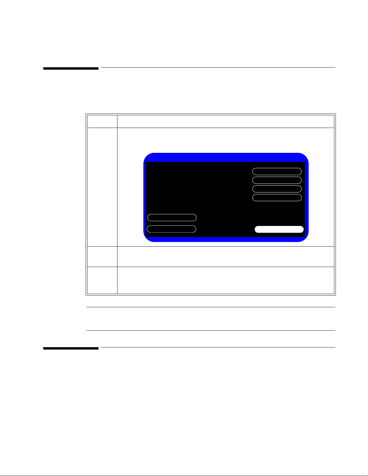
To access the System Admin Menu:
Step
1In the
System Menu, rotate the wheel until the System Admin button is
highlighted, and then press the wheel.
2 In the window that appears, enter the Administrator password,
shown:
3 Rotate the wheel until
The
System Admin Menu appears.
OK is highlighted, and then press the wheel.
2-1-5, as
Caution
During system configuration, the System Admin Menu remains unlocked
for 1 minute after you close it. This allows you to open the menu again
without having to re-enter the password. Do not leave the monitor
unattended during this time.
4Use the System Admin Menu to set system parameters. See the following
section for available options.
4-2 SureSigns VS2 Vital Signs Monitor Service Guide
Configuring the Monitor
Page 27

System Admin Menu Options
The following table describes the buttons in the System Admin Menu and the default settings.
Button Description Default
Accessing the System Admin Menu
Auto Suspend: Specifies the time interval for the monitor to
automatically enter suspend mode when the monitor
is running on battery power, no measurements are
ongoing, and the user does not touch the monitor.
Pressing the Power key turns the monitor back on.
For more detailed information, see “Setting Auto
Suspend” on page 4-5.
Auto Save Patient
Record:
Specifies the time an open record is automatically
saved and closed after it is opened, or after an NBP
or Temperature measurement is completed, or after
SpO
reading appears in the SpO2 pane, whichever
2
happens last. For SpO
, when there is no open
2
record, the auto save period starts when the record
is opened.
For more detailed information, see “Setting Auto
Save Patient Record” on page 4-5.
Default Alarm
Settings
Allows you to configure the alarm settings to be
used as defaults.
For more detailed information, see “Configuring the
Default Alarm Settings” on page 4-6.
Service Allows access to the following settings:
• Language
• Diagnostics
•Networking
• Export Settings
• Upgrade Software
• Shutdown
• Data Export
• Import Settings
For more detailed information, see “Configuring the
Service Settings” on page 4-12.
Off
1 minute
Philips
Depends on country
Configuring the Monitor
SureSigns VS2 Vital Signs Monitor Service Guide 4-3
Page 28

Accessing the System Admin Menu
Button Description Default
Patient ID Settings
Default Initial NBP
Inflation Pressure
Specifies which type of information used to identify
patients, including:
• Primary Identification MRN
• Default Location Blank
• MRN Checked
• Transaction ID Checked
• First Name Checked
• Middle Name Checked
• Last Name Checked
• Location ID Checked
• Operator ID Checked
For more detailed information, see “Configuring the
Patient Identification Settings” on page 4-17
Specifies the default cuff inflation pressure for
NBP.
For more detailed information, see “Configuring the
Default Initial NBP Inflation Pressure” on
page 4-19.
Adult: 160 mmHg
(21.3 kPa)
Pediatric: 140 mmHg
(18.7 kPa)
Neonate: 100 mmHg
(13.3 kPa)
Demo Mode Sets the monitor in Demo Mode. Demo Mode
allows the monitor to be demonstrated without
actually monitoring parameters.
For more detailed information, see “Setting Demo
Mode” on page 4-20.
Return Returns the monitor to the System menu or
previous menu.
Unchecked
—
Configuring the Monitor
4-4 SureSigns VS2 Vital Signs Monitor Service Guide
Page 29

Setting Auto Suspend
Use the Auto Suspend setting to configure the period of time after which the monitor will automatically
enter suspend mode when the monitor is not in use.
To set Auto Suspend:
Step
Setting Auto Suspend
1In the
System Admin Menu, rotate the wheel until the Auto Suspend menu is
highlighted.
2 Press the wheel and rotate it to select the from the following options:
•
Off
•5 minutes
•10 minutes
•15 minutes
•30 minutes
3 Press the wheel to save the setting.
4 Rotate the wheel until
Return is highlighted, and then press the wheel.
5 Press the Main Screen key on the front panel to close the menu.
Setting Auto Save Patient Record
Use the Auto Save Patient Record setting to configure the period of time after which the monitor will
automatically close and save the current open record.
Step
1In the
System Admin Menu, rotate the wheel until the Auto Save Patient Record menu is
highlighted.
2 Press the wheel and rotate it to select the from the following options:
•1 minute
•2 minutes
•3 minutes
3 Press the wheel to save the setting.
4 Rotate the wheel until
Return is highlighted, and then press the wheel.
5 Press the Main Screen key on the front panel to close the menu.
Configuring the Monitor
SureSigns VS2 Vital Signs Monitor Service Guide 4-5
Page 30
Configuring the Default Alarm Settings
OK
Please enter the password:
512
Cancel
Default Alarm Settings
Save Current Alarm Settings as Default
Restore Factory Default Alarm Settings
Return
Philips
Alarm Tone:
Minimum Nurse Call Alarm Priority:
Minimum Alarm Tone Volume:
Alarm Pause Duration:
Low
120 seconds
3
Allow Alarm Disable
Latch Physiological Alarms
Allow Audio Off
Configuring the Default Alarm Settings
You can set the default alarm settings that the monitor uses rather than the factory defaults. The factory
default settings are listed in “Factory Default Alarm Limits” on page 4-10.
Accessing the Default Alarm Settings Menu
To open the Default Alarm Settings Menu:
Step
1Press the
The
2 In the
System Menu key.
System Menu appears.
System Menu, rotate the wheel until the System Admin button is highlighted, and
then press the wheel.
3 In the window that appears, enter the Administrator password,
4 Rotate the wheel until
The
Default Alarm Settings appear:
Default Alarm Settings is highlighted, and then press the wheel.
2-1-5, as shown:
4-6 SureSigns VS2 Vital Signs Monitor Service Guide
Configuring the Monitor
Page 31

Configuring the Default Alarm Settings
The following table describes the buttons in the Default Alarm Settings menu and the default settings
Button Description Default
Alarm Tone: Specifies the type of alarm tones that the monitor uses.
See “Setting the Alarm Tone Pattern” on page 4-8.
Alarm Pause Duration: Specifies the amount of time for which alarms do not
sound when alarms are paused by the user.
See “Setting the Alarm Pause Duration” on page 4-8.
Minimum Nurse Call
Alarm Priority:
Specifies the minimum alarm level that triggers the nurse
call signal. For example, if the value is set to Medium,
Medium and High priority alarms will trigger the nurse call
signal, but Low will not.
See “Setting the Minimum Nurse Call Alarm Priority” on
page 4-9.
Minimum Alarm Tone
Volume:
Specifies the minimum volume of the alarm tone that the
monitor sounds.
See “Setting the Minimum Alarm Tone Volume” on
page 4-9.
Save Current Alarm
Settings as Default
Specifies that the monitor use the current alarm settings as
the default settings.
See “Changing the Default Alarm Settings” on page 4-10.
Restore Factory
Default Alarm Settings
Specifies that the monitor use the factory alarm settings as
the default settings.
Philips
120 seconds
Low
3
—
—
See “Changing the Default Alarm Settings” on page 4-10.
Latch Physiological
Alarms
Specifies that the monitor latches all physiological alarms.
This means that they will continue to sound until you
acknowledge the alarm by pressing the monitor’s
Silence
key.
Alarm
See “Latching Physiological Alarms” on page 4-11.
Allow Alarm Disable Specifies whether a user is allowed to disable monitor
alarms. Checking the box allows a user to disable alarms.
See “Restricting Alarm and Audio Settings” on page 4-11.
Allow Audio Off Specifies whether a user is allowed to turn off the alarm
audio on the monitor. Checking the box allows a user to
turn off the audio.
See “Changing the Default Alarm Settings” on page 4-10.
Unchecked
Checked
Checked
Configuring the Monitor
SureSigns VS2 Vital Signs Monitor Service Guide 4-7
Page 32

Configuring the Default Alarm Settings
Setting the Alarm Tone Pattern
The Alarm Tone setting controls the pattern of audible sounds during alarms.
The default setting is Philips.
To set the alarm tone:
Step
1In the
System Admin Menu, rotate the wheel until the Default Alarm Settings button is
highlighted and press the wheel.
2 Rotate the wheel until the
3 Press the wheel, and then rotate it to select the default setting for alarm tone. The options
are:
•Philips
•IEC
4 Press the wheel again to save the setting.
5 To return to the
System Admin Menu, rotate the wheel until Return is highlighted, and
then press the wheel or press the Main Screen key on the front panel to close the menu.
Setting the Alarm Pause Duration
Alarm Pause mode disables audible alarm notification for all current and future alarms for a configured
time. If the user presses the Alarm Silence key twice in two seconds, Alarm Pause mode activates, and a
banner appears displaying the message,
Alarm Pause mode ends.
When Alarm Pause mode ends, all current alarms become audible (except technical alarms), even if they
were silenced before entering Alarm Pause mode. When alarms are paused, the nurse call signal does not
alarm. This does not affect other alarm indication methods.
Alarm Ton e menu is highlighted.
Audio Paused, and counts down the remaining seconds until
The default setting is 120 seconds.
To configure the duration for which alarms are paused during alarm pause mode:
Step
1In the
System Admin Menu, rotate the wheel until the Default Alarm Settings button is
highlighted and press the wheel.
2 Rotate the wheel until the
Alarm Pause Duration menu is highlighted.
3 Press the wheel, and then rotate it to select the default setting for alarm pause duration.
The options are (in seconds):
30, 60, 90, 120, 180.
4 Press the wheel again to save the setting.
5 To return to the
System Admin Menu, rotate the wheel until Return is highlighted, and
then press the wheel or press the Main Screen key on the front panel to close the menu.
Configuring the Monitor
4-8 SureSigns VS2 Vital Signs Monitor Service Guide
Page 33

Setting the Minimum Nurse Call Alarm Priority
The nurse call signal is a physical connection on the monitor that can connect to a variety of external
signals. For example, lights, alarm buzzers, or paging systems. When any alarm condition exists, the
nurse call signal activates.
You can configure the alarm priority that triggers the nurse call signal. Pausing (or turning off) alarms,
turns off the nurse call signal. The nurse call alarm priority is the minimum alarm priority level that
triggers the nurse call signal. The value is inclusive. For example, if the value is set to medium, and then
anything other than a low priority alarm triggers the nurse call signal.
The default is
To configure the nurse call alarm priority:
Step
1In the System Admin Menu, rotate the wheel until the Default Alarm Settings button is
Low.
highlighted.
Configuring the Default Alarm Settings
2 Rotate the wheel until the
Minimum Nurse Call Alarm Priority menu is highlighted.
3 Press the wheel, and then rotate it to select
4 Press the wheel to save the selected priority.
5 To return to the
System Admin Menu, rotate the wheel until Return is highlighted, and
then press the wheel or press the Main Screen key on the front panel to close the menu.
Setting the Minimum Alarm Tone Volume
You can configure the minimum volume to which the user can set the monitor.
The default setting is 3.
To set the minimum alarm tone volume:
Step
1In the
2 Rotate the wheel until the
3 Press the wheel and rotate it to select the default setting for the minimum alarm tone
System Admin Menu, rotate the wheel until the Default Alarm Settings button is
highlighted and press the wheel.
Minimum Alarm Tone Volume menu is highlighted.
volume that a user can set. The volume options are:
Low, Medium, or High priority.
1–10.
4 Press the wheel again to save the setting.
5 To return to the
System Admin Menu, rotate the wheel until Return is highlighted, and
then press the wheel or press the Main Screen key on the front panel to close the menu.
SureSigns VS2 Vital Signs Monitor Service Guide 4-9
Configuring the Monitor
Page 34

Configuring the Default Alarm Settings
Changing the Default Alarm Settings
You can set the default alarm settings by either configuring the current monitor settings as the default or
by restoring the original factory settings. “Factory Default Alarm Limits” below lists the factory alarm
settings.
To change the default alarm setting:
Step
1In the
highlighted and press the wheel.
2 Rotate the wheel until either the
Factory Default Alarm Settings
setting.
3 In the window that appears, rotate the wheel to select
The monitor uses this setting (current or factory settings) as the default alarm setting value.
4 To return to the
then press the wheel or press the Main Screen key on the front panel to close the menu.
Factory Default Alarm Limits
The following table lists the factory default alarm limits.
Heart Rate 120 bpm 50 bpm 160 bpm 75 bpm 200 bpm 100 bpm
NBP
Diastolic
NBP MAP
(Mean)
NBP
Systolic
SpO
2
Temperature
System Admin Menu, rotate the wheel until the Default Alarm Settings button is
Save Current Alarm Settings as Default or Restore
button is highlighted, and then press the wheel to save the
Yes, and then press the wheel.
System Admin Menu, rotate the wheel until Return is highlighted, and
Adult Pediatric Neonatal
High Low High Low High Low
90 mmHg
(12.0 kPa)
110 mmHg
(14.6 kPa)
160 mmHg
(21.3 kPa)
50 mmHg
(6.6 kPa)
70 mmHg
(8.0 kPa)
90 mmHg
(12.0 kPa)
70 mmHg
(9.3 kPa)
90 mmHg
(12.0 kPa)
120 mmHg
(16.0 kPa)
40 mmHg
(5.3 kPa)
50 mmHg
(6.6 kPa)
70 mmHg
(9.3 kPa)
60 mmHg
(8.0 kPa)
70 mmHg
(9.3 kPa)
90 mmHg
(12.0 kPa)
20 mmHg
(2.6 kPa)
24 mmHg
(3.2 kPa)
40mmHg
(5.3 kPa)
100% 90% 100% 90% 95% 85%
102.2
o
39
C
o
F
96.8
o
36
o
F
C
102.2
o
39
C
o
F
96.8
36
o
F
o
C
102.2
o
39
C
o
F
96.8
36
o
F
o
C
Configuring the Monitor
4-10 SureSigns VS2 Vital Signs Monitor Service Guide
Page 35

Restricting Alarm and Audio Settings
You can control whether a user can disable alarms and/or turn off the audio.
To set whether or not a user can disable alarms and audio:
Step
Configuring the Default Alarm Settings
1In the
System Admin Menu, rotate the wheel until the Default Alarm Settings button is
highlighted and press the wheel.
2 Rotate the wheel until the
highlighted.
3 Press the wheel to insert a check in the box to allow a user to disable alarms or turn off the
audio.
4 To return to the
then press the wheel or press the Main Screen key on the front panel to close the menu.
Latching Physiological Alarms
You can set all physiological alarms to be latched alarms. Latched alarms continue to sound until they are
acknowledged at the monitor by pressing the Alarm Silence key.
To latch all physiological alarms:
Step
1Open the
2 Rotate the wheel until the
System Admin Menu. See “Accessing the System Admin Menu” on page 4-1.
Allow Alarm Disable or Allow Audio Off check box is
System Admin Menu, rotate the wheel until Return is highlighted, and
Latch Physiological Alarms check box is highlighted.
3 Press the wheel to insert a check in the box.
4 To return to the
System Admin Menu, rotate the wheel until Return is highlighted, and
then press the wheel or press the Main Screen key on the front panel to close the menu.
SureSigns VS2 Vital Signs Monitor Service Guide 4-11
Configuring the Monitor
Page 36

Configuring the Service Settings
OK
Please enter the password:
512
Cancel
Service Menu
Diagnostics
Networking
Data Export
Upgrade Software
Import Settings
Export Settings
Language:
Return
Shutdown
English
Shutdown
Configuring the Service Settings
Accessing the Service Menu
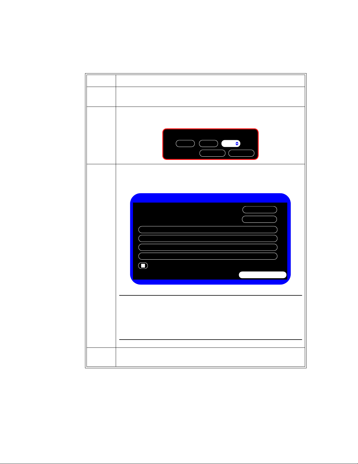
To open the Service Menu:
Step
1Press the
The
2 In the
System Menu key.
System Menu appears.
System Menu, rotate the wheel until the System Admin button is highlighted, and
then press the wheel.
3 In the window that appears, enter the Administrator password,
4 Rotate the wheel until
The
Service Menu appears:
Service is highlighted, and then press the wheel.
2-1-5, as shown:
4-12 SureSigns VS2 Vital Signs Monitor Service Guide
Configuring the Monitor
Page 37

Configuring the Service Settings
The following table describes the options in the Service Menu and the default settings.
Button Description Default
Language: Specifies which language the monitor displays.
Changing the language setting opens a confirmation window;
pressing
OK reboots the monitor.
For instructions for setting the language, see “Selecting a
Language” on page 4-14.
Diagnostics Displays the System Diagnostics menu. Monitoring is
suspended while this menu is open. The
Diagnostics button is
unavailable when the monitor is running in Demo mode.
For more information about using the
System Diagnostics
menu, see Chapter 5, “Performance Verification Testing” and
“System Admin Menu Options” on page 4-3.
Networking Displays the Network Configuration menu. Use this menu to set
up how the monitor connects to a network. For more information
about using the monitor on a network or exporting data, see the
SureSigns VS2 Data Export Guide.
Export Settings Exports monitor configuration settings to a USB flash drive.
See “Exporting Configuration Settings” on page 4-14.
Upgrade Software Displays the confirmation window for upgrading the monitor
software.
See “Upgrading the Software” on page 4-15.
Depends on
country
—
—
—
—
Shutdown Shuts down the monitor (for battery change) after you press OK
in the confirmation window.
For more information, see “Performing a Hard Shutdown” on
page 7-2.
Data Export Displays the Data Export window. Use this menu to set up
where the monitor exports data. For more information about
using the monitor on a network or exporting data, see the
SureSigns VS2 Data Export Guide.
Import Settings Imports monitor configuration settings from a USB flash drive.
See “Importing Configuration Settings” on page 4-17.
—
—
—
Configuring the Monitor
SureSigns VS2 Vital Signs Monitor Service Guide 4-13
Page 38

Configuring the Service Settings
Selecting a Language
You can configure a variety of languages on the monitor. The default language is English.
To change the language:
Step
1In the
Service Menu, rotate the wheel until the Language menu is highlighted, and then
press the wheel. (To access the Service Menu, see “Accessing the Service Menu” on
page 4-12.)
2 Rotate the wheel to select the language in which you want to use the monitor from the
following options:
•English
•Spanish
•German
• French
•Italian
•Dutch
• Portuguese
• Russian
3 Press the wheel again to save the setting.
A window appears warning that to change the language, the system must restart.
4 In the window, rotate the wheel to
and restart the system.
Exporting Configuration Settings
Yes, and then press the wheel to change the language
Use Export Settings to transfer the user settings, using a USB flash drive, from one monitor to other
monitors with the same hardware configuration and same software version.
The following data are exported:
• All system settings, except: Maintenance settings in the
Static IP address, Static Subnet address, and Static Gateway address
• All settings in the menus
• All settings (except alarm limits, alarm enables and Initial NBP Inflation Pressure for the current
patient) in all number pane menus
• User default settings of the alarm limits and alarm enables
• Error log database
• Patient record database
• Patient list database
For information about importing the exported settings into another monitor, see “Importing Configuration
Settings” on page 4-17.
Configuring the Monitor
4-14 SureSigns VS2 Vital Signs Monitor Service Guide
Diagnostics section, Monitor Name,
Page 39

To export settings to a USB flash drive:
Step
1 Insert a USB flash drive into the USB port.
Configuring the Service Settings
2In the
Service Menu, rotate the wheel until the Export Settings is highlighted, and then
press the wheel. (To access the Service Menu, see “Accessing the Service Menu” on
page 4-12.)
A message appears displaying the name of the exported file in the format:
<product name >_<hardware configuration>_<software version>.cfg
3 Press the wheel to select OK and return to the Service Menu.
Upgrading the Software
Caution Charge the battery before upgrading the software. The monitor should not be connected to a
patient when the upgrade is performed. Disconnect any USB peripherals. If the USB port has a
clamp in place, you may need to remove the clamp to ensure that the flash drive fits properly.
Once the upgrade starts:
• Do not unplug the monitor.
• Do not remove the USB flash drive.
• Do not press any keys.
User interaction during the upgrade can cause the upgrade to fail.
To upgrade the software:
Step
1 Connect the monitor to AC power and turn on the monitor.
2 Insert the USB flash drive with the software upgrade into the USB port on the back of the
monitor.
Note — Philips recommends using a SanDisk
®
or Kingston® USB flash drive for software
upgrades.
Configuring the Monitor
SureSigns VS2 Vital Signs Monitor Service Guide 4-15
Page 40

Configuring the Service Settings
Upgrade Software
Return
Current Version:
Upgrade
A.01.42
A.01.50
New Version
WARNING: Battery should be charged before upgrading
software. Do not unplug the monitor, remove the USB flash
drive, or press any keys after the upgrade process begins. Any
user interaction during the upgrade may cause the upgrade to
fail and adversely affect monitor performance.
3In the System Admin Menu, rotate the wheel to highlight the Upgrade Software button,
and then press the wheel.
The monitor looks for a valid software image on the USB flash drive and displays the
updated image information in the
Upgrade Software window.
4 Rotate the wheel to highlight the
Caution
If a loss of power interrupts the upgrade progress, the monitor cannot boot. If this
happens, contact the Customer Care Center or a Philips representative.
The system saves the data and the upgrade process begins. Progress information indicates
the current status of the upgrade.
After the software upgrade, the monitor restarts.
5 Remove the USB flash drive.
Upgrade button and press the wheel to start the upgrade.
4-16 SureSigns VS2 Vital Signs Monitor Service Guide
Configuring the Monitor
Page 41

Importing Configuration Settings
Use Import Settings to import user settings from a USB flash drive containing settings from a monitor
with the same hardware configuration and same software version.
The monitor restarts after importing.
To import settings:
Step
1 Insert a USB flash drive containing exported settings into the USB port.
For more information about exporting settings, see “Exporting Configuration Settings” on
page 4-14.
Configuring the Patient Identification Settings
2In the
3 Rotate the wheel to highlight Yes and then press the wheel.
4 Press the wheel to select
Service Menu, rotate the wheel until the Import Settings is highlighted, and then
press the wheel.
A message appears asking you to confirm the file to import.
When the import is complete, the message,
OK and restart the monitor.
The system will restart now., appears.
Configuring the Patient Identification Settings
Changing the Patient ID Settings
Use Patient ID Settings to select the identification fields to be used in the New Patient Menu and assign
one field as the patient primary identification. After the primary identification is selected, the
corresponding checkbox cannot be selected.
Caution When you change the patient primary identification, the patient record database is cleared.
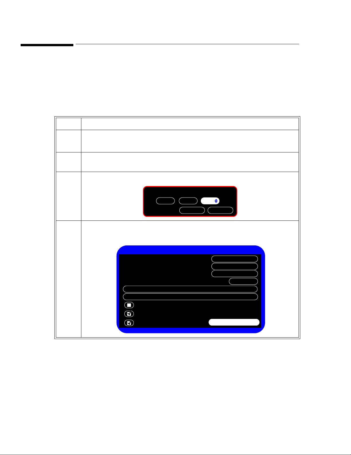
To access the Patient ID Settings:
Step
1 Press the
The
2 In the
then press the wheel.
System Menu key.
System Menu appears.
System Menu, rotate the wheel until the System Admin button is highlighted, and
Configuring the Monitor
SureSigns VS2 Vital Signs Monitor Service Guide 4-17
Page 42

Configuring the Patient Identification Settings
OK
Please enter the password:
512
Cancel
Patient ID Settings
Primary Identification:
Return
MRN
Changing the Primary Identification will clear all patient data.
Default Location:
MRN:
Transaction ID:
First Name:
Middle Name:
Last Name:
Location ID:
Operator ID:
3 In the window that appears, enter the Administrator password,
4 Rotate the wheel until
The
Patient ID Settings appear:
Patient ID Settings is highlighted, and then press the wheel.
2-1-5, as shown:
5 Configure the settings as needed for your institution.
The following table describes the Patient ID Settings.
Button Description
Primary
Identification:
Default Location: The physical location of the monitor that will be automatically entered with
Specifies which type of identifying information,
Location ID, is the default primary patient identification used in the New
Patient Menu
each new patient in the
MRN: Medical Record Number. A unique number used to track and identify a
patient. The maximum length is 20 characters.
Transaction ID: Also known as the visit ID, the transaction ID is a unique number used to
track a single patent visit. The maximum length is 20 characters.
First Name: Patient’s first name. The maximum length is 15 characters.
Middle Name: Patient’s middle name. The maximum length is 15 characters.
Last Name: Patient’s last name. The maximum length is 15 characters.
Location ID: Typically, a description of the physical location of the VS2 monitor, for
example, a room number. The maximum length is 15 characters.
MRN, Transaction ID, or
.
New Patient Menu.
4-18 SureSigns VS2 Vital Signs Monitor Service Guide
Operator ID: The identification of the person using the VS2 to measure a patient’s vital
Configuring the Monitor
signs. The maximum length is 15 characters.
Page 43

Configuring the Default Initial NBP Inflation Pressure
Configuring the Default Initial NBP Inflation Pressure
You can specify the initial NBP inflation pressure value for Adult, Pediatric, and Neonatal patients. The
monitor uses this default value for new patient starts.
The default is:
• Adult: 160 mmHg (21.3 kPa)
• Pediatric: 140 mmHg (18.7 kPa)
• Neonatal: 100 mmHg (13.3 kPa)
To change the NBP and alarm setting values:
Step
1In the
System Admin Menu, rotate the wheel until the Default Initial NBP Inflation
Pressure
menu is highlighted.
2 For each patient type, press the wheel and rotate it to select the initial NBP cuff inflation
pressure.
The options are:
•
Adult: 80–240 mmHg in 20 mmHg steps (10.7–31.9 kPa in 2.7 kPa steps)
•
Pediatric: 80–240 mmHg in 20 mmHg steps (10.7–31.9 kPa in 2.7 kPa steps)
•
Neonate: 60–120 mmHg in 20 mmHg steps (8.0–16.0 kPa in 2.7 kPa steps)
3 Press the wheel to save the settings.
4 Rotate the wheel until
Return is highlighted, and then press the wheel.
5 Press the Main Screen key on the front panel to close the menu.
Configuring the Monitor
SureSigns VS2 Vital Signs Monitor Service Guide 4-19
Page 44

Setting Demo Mode
Setting Demo Mode
Warning Do not connect a patient to the monitor running in Demo mode. Values represented in Demo mode
do not represent measurements from a patient connected to the monitor, and may lead to incorrect
diagnoses.
Demo mode lets you demonstrate the monitor without monitoring parameters. Demo mode simulates all
the low-level data source components, including NBP. Demo mode generates alarms when alarm settings
are exceeded.
The default is regular user mode.
Entering or exiting demo mode clears the patient data.
To set the monitor to Demo mode:
Step
1In the
highlighted and press the wheel to insert a check in the Demo Mode box.
2 Rotate the wheel to highlight
A window appears asking if you want to enter demo mode and clear all patient data.
3 In the window, rotate the wheel to
4 Rotate the wheel to highlight
activates, and a
5 To exit
The monitor clears all patient data.
Clearing Patient Data
System Admin Menu, rotate the wheel until the Demo Mode check box is
Return and press the wheel to select it.
Yes, and press the wheel again to select it.
Main Screen and press the wheel to select it. Demo mode
DEMO banner appears in the message area.
Demo Mode, press the Power key to turn the monitor off.
Resetting the system clears all of memory and patient data, except for calibration and hardware
configuration data. When you reconfigure a system, you should reset the system first.
To reset the system data:
Step
1In the
System Admin Menu, rotate the wheel until the
then press the wheel.
The
Service Menu appears.
Configuring the Monitor
4-20 SureSigns VS2 Vital Signs Monitor Service Guide
Service
button is highlighted and
Page 45

Clearing Patient Data
System Diagnostics
Monitoring Suspended
LCD Usage Hours: 231
Errors: 0
Display Test
Self Test
Audio Test
LED Test
Battery Info
Maintenance >>
Keys Test
NBP Cycle Count: 36
Return
Recorder Test
Error Log
OK
Please enter the password:
921
Cancel
Return
CO2 Test
IBP Calibration
System Diagnostics
Monitoring Suspended
LCD Usage Hours: 231
Errors: 0
Display Test
Self Test
Audio Test
LED Test
Battery Info
Keys Test
NBP Cycle Count: 36
Return
Recorder Test
Error Log
Configuration
NBP Test
Reset S/N
Reset
Reset
Reset
Clear Data
2 Rotate the wheel until the
The
System Diagnostics menu appears.
3 Select the
Maintenance >> button and press the wheel.
Diagnostics
button is highlighted and then press the wheel.
4 In the window that appears, enter the password,
1-2-9, as shown:
The
Maintenance options appear.
5 Rotate the wheel to highlight the
Clear Data button, and then press the wheel.
6 In the window that appears, rotate the wheel to select
The monitor restarts, clears all data, and resets the system.
SureSigns VS2 Vital Signs Monitor Service Guide 4-21
Yes, and press the wheel.
Configuring the Monitor
Page 46

Installing the Power Cord Retainer Clip
Retainer clip
Installing the Power Cord Retainer Clip
Warning Secure the external power supply cable to the roll stand or wall mount to prevent patient
entanglement or strangulation.
To install the power cord retainer clip:
Step
1 Insert the power cable into the monitor.
2 Slide the retainer clip over the power cord.
3 Secure the retainer clip to the monitor with the T20 Torx screw.
Configuring the Monitor
4-22 SureSigns VS2 Vital Signs Monitor Service Guide
Page 47

Installing the USB Hub
Hub
USB Port
Installing the USB Hub
Warning To ensure patient electrical isolation, connect only to other equipment that provides
patient electrical isolation. Use only unshielded network cables.
A USB hub enables you to use the RS-232 serial interface adapter (see “Installing the RS-232 Serial
Interface Adapter”on page 4-24) and a barcode scanner on the monitor at the same time.
Step
1 Shut down the monitor as described in “Performing a Hard Shutdown” on page 7-2.
2 Remove the backing from the mounting stickers on the hub.
3 Place the hub on the back of the monitor and connect the hub USB cable to the monitor
USB port.
4 Connect the RS-232 serial interface adapter cable to one of the hub USB ports and the
barcode scanner cable to another of the hub USB ports.
Caution
Do not allow liquid to penetrate connectors or openings on the hub. Wet connectors
could prevent connected devices from operating. If liquid spills on the hub, clean and
dry it thoroughly before reuse. If you believe the liquid may have gotten inside the
hub, contact your biomedical engineer, who can verify the performance and safety of
the equipment.
Configuring the Monitor
SureSigns VS2 Vital Signs Monitor Service Guide 4-23
Page 48

Installing the RS-232 Serial Interface Adapter
Clamp
Installing the RS-232 Serial Interface Adapter
You can use an optional USB/RS-232 serial interface adapter to export patient data. For more
information, see the SureSigns VS2 Data Export Guide.
Warning To ensure patient electrical isolation, connect only to other equipment that provides
patient electrical isolation. Use only unshielded network cables.
Note — If you are also using a barcode scanner on the monitor, install the USB hub first. See “Installing
the USB Hub” on page 4-23.
To install the RS-232 serial adapter:
Step
1 Shut down the monitor as described in “Performing a Hard Shutdown” on page 7-2.
2 Clean the site where the USB clamp attaches to the monitor. This ensures that the clamp
attaches securely. For cleaning instructions, see the instructions on “Cleaning and
Disinfecting the Monitor” on page 3-2.
3 Peel the paper from the foam pad on the USB clamp and attach the clamp to the rear of the
monitor.
4 Slide the adapter’s USB plug through the clamp and into the port.
Configuring the Monitor
4-24 SureSigns VS2 Vital Signs Monitor Service Guide
5 Tighten the screws on the USB clamp with a #1 Phillips-head screwdriver.
Page 49

Installing the RS-232 Serial Interface Adapter
Step
6 Insert the other end of the USB cord into the adapter.
7 Slide the insulator sheath over the adapter, wide end first, and push it down to completely
cover the adapter.
8 Attach the adapter to the RS-232 serial port of the export device.
Caution
Do not allow liquid to penetrate connectors or openings on the adapter. Wet
connectors could prevent connected devices from operating. If liquid spills on the
adapter, clean and dry it thoroughly before reuse. If you believe the liquid may have
gotten inside the adapter, contact your biomedical engineer, who can verify the
performance and safety of the equipment.
Configuring the Monitor
SureSigns VS2 Vital Signs Monitor Service Guide 4-25
Page 50

Installing the RS-232 Serial Interface Adapter
Removing the Insulator Sheath
To remove the adapter insulator sheath:
• Pull apart the wide side of the sheath with your fingers and push on the adapter metal connector
with your thumbs to slide the adapter out of the sheath.
Configuring the Monitor
4-26 SureSigns VS2 Vital Signs Monitor Service Guide
Page 51

Overview
5
Performance Verification Testing
This chapter includes the following information:
• Testing and inspection guidelines
• Recommended frequency of performance text
• Test procedures following monitor repair or during routine maintenance
If the monitor fails any test, it must be repaired before it is returned to use.
Note — The procedures in this chapter assume knowledge of basic monitor operation. For details on
using the monitor, see the SureSigns VS2 Vital Signs Monitor Instructions for Use.
Testing and Inspection Guidelines
The following table lists the tests that Philips requires that you complete after performing monitor
installations, repairs, or software upgrades.
See Chapter 3, “Performing Routine Maintenance,” for information on routine maintenance.
See Chapter 7, “Repairing the Monitor,” for information on repair procedures.
After … Complete These Tests …
Installing or exchanging a monitor • Visual inspection
Upgrading the software • Visual inspection
Opening the monitor for any reason • Power-on
Replacing any internal parts
(except NBP parts, SpO
Replacing the NBP module or parts • Power-on
Replacing the SpO
• Power-on
• Power-on
• Pneumatic leakage
• All safety tests
• Power-on
board)
2
board • Power-on
2
• Pneumatic leakage
• All safety tests
•NBP test
• Pneumatic leakage
• All safety tests
•SpO
• Pneumatic leakage
• All safety tests
Test
2
Performance Verification Testing
SureSigns VS2 Vital Signs Monitor Service Guide 5-1
Page 52

Recommended Frequency
Recommended Frequency
Perform the test procedures at the recommended frequency outlined in the following table.
Caution The frequency recommendations in the following table do not supersede local requirements. Always
perform locally required testing in addition to the testing outlined in the table.
Suggested Testing Frequency
Preventive Maintenance
NBP calibration Once every two years, or more often if specified by
local laws.
Performance
• Temperature accuracy
• NBP accuracy test
•SpO
• Nurse call relay
Safety—Patient leakage current
2
1
In accordance with IEC 60601-1
1. When used as part of facility protocols
Required Test Equipment
The following table lists the additional test equipment that you need to perform each of the tests in this
chapter. Many of these tests also use the standard accessories that are shipped with the monitor.
To Perform This Test … You Need This Test Equipment …
“Visual Test” on page 5-6 None
“Power-On Self Test” on page 5-7 None
“Alarms Test” on page 5-7 NBP cuff
“SpO2 Test” on page 5-8 Adult SpO
“NBP Test” on page 5-9 • Reference manometer (includes hand pump and
“Temperature Test” on page 5-13 SureSigns temperature calibration key
“Safety Test” on page 5-14 Multimeter
Once every two years, or if you suspect the
measurement is incorrect.
Once a year and after repairs where the unit has been
opened (front and back separated) or the monitor has
been damaged by impact.
sensor
2
valve), accuracy 0.2% of reading
• Expansion chamber (volume 500 ml ± 10%)
• Appropriate tubing
(part number 4535 640 33691)
Performance Verification Testing
5-2 SureSigns VS2 Vital Signs Monitor Service Guide
Page 53

To Perform This Test … You Need This Test Equipment …
“Nurse Call Relay Test” on page 5-15 • Patient simulator
“Barcode Scanner Test” on page 5-19 Barcode scanner
Test Recording
Authorized Philips personnel report test results back to Philips to add to the product development
database. Hospital personnel, however, do not need to report results.
The following table describes what to record on the service record after you complete the tests in this
chapter.
Note: P = pass, F = fail, X = measured value as defined in tests in this chapter
Test Recording
• Ohmmeter
• Phono connector
Test What to record
Visual V:P or V:F
Power-On PO:P or PO:F
NBP NBP:P/X1/X2/X3 or
NBP:F/X1/X2/X3
Safety S(3): P/X1 or S(3): F/X1
Performing Verification Tests
Some of the verification tests require using the Diagnostics menu or the Maintenance options. When
you enter the Diagnostics menu, monitoring is suspended.
Note — The System Diagnostics menu is not available in Demo mode.
To access the
Step
1 Press the
2 Rotate the wheel until the
System Diagnostics menu:
System Menu key.
The
System Menu appears.
System Admin button is highlighted, and then press the wheel.
Performance Verification Testing
SureSigns VS2 Vital Signs Monitor Service Guide 5-3
Page 54

Performing Verification Tests
OK
Please enter the password:
512
Cancel
System Admin Menu
Return
Demo Mode
Default Initial NBP Inflation Pressure
Service
Default Alarm Settings
Patient ID Settings
Auto Suspend:
Auto Save Patient Record:
Off
1 minute
3 In the window that appears, enter the Administrator password, 2-1-5, as shown:
4 Rotate the wheel until
The
System Admin Menu appears.
OK is highlighted, and then press the wheel.
5-4 SureSigns VS2 Vital Signs Monitor Service Guide
Performance Verification Testing
Page 55

Performing Verification Tests
Service Menu
Diagnostics
Networking
Data Export
Upgrade Software
Import Settings
Export Settings
Language:
Return
Shutdown
English
Shutdown
System Diagnostics
Monitoring Suspended
LCD Usage Hours: 231
Errors: 0
Display Test
Self Test
Audio Test
LED Test
Battery Info
Maintenance >>
Keys Test
NBP Cycle Count: 36
Return
Recorder Test
Error Log
5 Rotate the wheel until Service is highlighted, and then press the wheel.
The
Service Menu appears.
6 Rotate the wheel until
The
System Diagnostics window appears.
Diagnostics is highlighted, and then press the wheel.
Performance Verification Testing
SureSigns VS2 Vital Signs Monitor Service Guide 5-5
Page 56

Visual Test
OK
Please enter the password:
921
Cancel
Return
CO2 Test
IBP Calibration
System Diagnostics
Monitoring Suspended
LCD Usage Hours: 231
Errors: 0
Display Test
Self Test
Audio Test
LED Test
Battery Info
Keys Test
NBP Cycle Count: 36
Return
Recorder Test
Error Log
Configuration
NBP Test
Reset S/N
Reset
Reset
Reset
Clear Data
To access the Maintenance options:
Step
1In the
System Diagnostics window, rotate the wheel to highlight the
Maintenance >> button and press the wheel.
2 In the window that appears, enter the password,
3 The
Maintenance options appear.
1-2-9, as shown:
Visual Test
To perform the visual test:
Step
1 Inspect the system for obvious signs of damage. For example: cracks, cuts, or breakage.
2 Check all external cables and accessories for damage. For example: cuts, kinks, or wrong
connections.
3 Ensure that all markings and labeling are legible.
Performance Verification Testing
5-6 SureSigns VS2 Vital Signs Monitor Service Guide
4 Check for any obstructions to mechanical parts.
The expected test result is that the system has no obvious signs of damage or obstruction.
Page 57

Power-On Self Test
To perform the power-on self test:.
Step
1 Connect the monitor to the external power supply and plug the power supply cord into an
AC power source.
2 Press the Power key to turn on the monitor.
3 Make sure that the monitor boots up successfully as described in the following sequence:
• The screen displays color bars for about five seconds.
• The LCD turns off for three seconds, and the battery LED lights.
• The Philips screen appears for one second, and a startup tone sounds.
• The main screen appears.
The expected result is that the monitor boots up and displays the main (or appropriate)
screen. For detailed information on the boot and power sequences, see “Boot and Power
Sequences” on page 6-4.
If the LEDs do not function as expected, see “Power Problems” on page 6-6.
Power-On Self Test
Alarms Test
To perform this test, you need an NBP cuff and hose.
To verify that the general monitor alarms are working, test them while using the NBP
function.
To test the monitor alarm:
monitoring
Step
1 With the monitor turned on, make sure that all alarms are enabled (the monitor is not in
Audio Pause or Audio Off mode).
2 Make sure the NBP alarm is enabled (the crossed bell icon does not appear in the NBP
numeric pane).
3 Connect the NBP hose to the NBP input connector, but do not place the cuff on your arm.
4 Press the NBP button on the front panel.
5 Check that the NBP Timeout or NBP Loose Cuff message appears and an alarm tone
sounds.
6 If you do not get the results in Step 5, see Chapter 6, “Troubleshooting”.
Performance Verification Testing
SureSigns VS2 Vital Signs Monitor Service Guide 5-7
Page 58

SpO2 Test
SpO2 Test
This test checks the performance of the SpO2 measurement.
To perform this test, you need:
• Adult SpO
To perform the SpO
transducer: M1191A, M1191AL, M1191B, M1191BL, or M1196A
2
Test:
2
Step
1 Connect an adult SpO
transducer that you know to be working correctly to the SpO2
2
connector on the monitor. Ensure that the red LED in the transducer is lit.
2 Connect the other end of the transducer to your finger (this assumes that you are healthy).
3 Verify that the SpO
value displayed on the monitor is between 95% and 100%. If it is not,
2
try the test again with a patient simulator.
4 If you still do not get the expected results, see “SpO2 Measurement Problems” on
page 6-11
sensor accuracy was obtained by performing controlled hypoxie studies on healthy, non-smoking
SpO
2
adult volunteers (according to EN ISO 9919). The SpO
readings have been compared to CO-oximeter
2
measurements on arterial blood samples. To represent the general population, data from at least 10
subjects (male and female) with a wide range of skin color was taken to validate SpO
accuracy. Because
2
pulse oximeter equipment measurements are statistically distributed, only approximately two-thirds of
pulse oximeter equipment measurements can be expected to fall within the ± Arms value measured by a
CO-oximeter.
The update rate for the SpO
processing on the displayed and transmitted data values of SpO
user-selectable SpO
Response Mode: Slow (20 seconds), Normal (10 seconds), and Fast (5 seconds).
2
value and pulse rate is typically 1 second. Data averaging and other signal
2
and pulse rate is controllable by the
2
Depending on the magnitude of difference between the alarm limit and the displayed value, the alarm
signal generation delay may be from 1 second to the value of the response time (5, 10, or 20 seconds).
Caution A functional tester cannot be used to assess the accuracy of a pulse oximeter monitor. However, if
there is independent demonstration that a particular calibration curve is accurate for the
combination of a pulse oximeter monitor and a pulse oximeter sensor, then a functional tester can
measure the contribution of a monitor to the total error of a monitor/sensor system. The functional
tester can then measure how accurately a particular pulse oximeter monitor is reproducing that
calibration curve.
Performance Verification Testing
5-8 SureSigns VS2 Vital Signs Monitor Service Guide
Page 59

NBP Test
SureSigns VM Patient Monitor
Expansion chamber SureSigns VS2 monitorManometer
These tests check the performance of the non-invasive blood pressure measurement. Perform each of
these NBP checks and procedures when checking the NBP unit:
• NBP accuracy
• NBP calibration procedure (if required)
• NBP pneumatic leakage
• NBP overpressure valve
To perform this test, you need:
• Reference manometer (includes hand pump and valve), accuracy 0.2% of reading
• Expansion chamber (volume 500 ml ± 10%)
• Appropriate tubing
NBP Accuracy
To test the NBP accuracy:
NBP Test
Step
1 Connect the manometer and the pump with tubing to the NBP connector on the SureSigns
VS2 monitor.
2 Connect the tubing to the expansion chamber (500 ml cylinder).
3 Connect the manometer and the pump with tubing to the NBP connector on the SureSigns
VS2 monitor.
4Open the
information on accessing the
Maintenance options (see “Performing Verification Tests” on page 5-3 for
Maintenance options).
Performance Verification Testing
SureSigns VS2 Vital Signs Monitor Service Guide 5-9
Page 60

NBP Test
NBP Test
Return
NBP Calibration
Start Static Pressure Test
Stop Static Pressure Test
Firmware version: 2.2
Pressure (mmHg):
5 Turn the wheel to highlight NBP Test, and then press the wheel.
The
NBP Test window appears.
6 Rotate the wheel to highlight the
Start Static Pressure Test button and press the wheel to
start the test.
7 Squeeze the manometer pump and apply a pressure of 50 mmHg.
8 Note the pressure displayed in the
NBP Test window and record this result as X1 (see
“Test Recording” on page 5-3). It should be 50 mmHg ± 3 mmHg.
9 Squeeze the manometer pump to apply a pressure of 250 mmHg to the monitor.
10 Note the pressure displayed in the
pressure in the
11 Press the
NBP Test window should be 250 mmHg ± 3 mmHg.
Stop Static Pressure Test button to stop the test.
NBP Test window and record this result as X2. The
12 If you do not get the expected results, calibrate the monitor (see “NBP Calibration
Procedure” on page 5-11).
If the results are as expected, continue with the “Pneumatic Leakage Test” on page 5-12.
5-10 SureSigns VS2 Vital Signs Monitor Service Guide
Performance Verification Testing
Page 61

NBP Calibration Procedure
NBP Calibration
Return
Set Pressure Value
:
0
0
Start
Stop
CAL P2
CAL P1
To calibrate the NBP module:
Step
NBP Test
1In the
NBP Test window, rotate the wheel to select NBP Calibration, and then press the
wheel.
The
NBP Calibration window appears.
2 Rotate the wheel to highlight the
Start button, and then press the wheel to begin
calibration.
Note — To stop the calibration process at any time, rotate the wheel to select
then press the wheel to stop calibration.
3 Squeeze the manometer pump to apply a pressure of 250 mmHg to the monitor.
Stop, and
4In the
NBP Calibration window, rotate the wheel to the Set Pressure Value: menu and
press the wheel. Rotate it to 250, and then press the wheel to save the value.
5 Rotate the wheel to
CAL P1, and then press the wheel to save this as the first calibration
point.
6 Release the pressure in the manometer to 50 mmHg.
7In the
NBP Pressure window, rotate the wheel to the Set Pressure Value menu, and then
press the wheel and rotate it to 50, and press the wheel to save the setting.
8 Rotate the wheel to select
CAL P2, and press the wheel to save this as the second
calibration point.
9 Rotate the wheel to highlight the
The message,
10 Rotate the wheel to the
11 To verify calibration, repeat the
12 If you do not get the expected results after several attempts, see “NBP Problems” on
page 6-9.
NBP calibration successful, appears.
Return button and press the wheel to exit the test.
Stop button and press the wheel to stop the test.
NBP Accuracy Test in “NBP Accuracy” on page 5-9.
Performance Verification Testing
SureSigns VS2 Vital Signs Monitor Service Guide 5-11
Page 62

NBP Test
Pneumatic Leakage Test
To check the pneumatic system and valve:
Step
1In the
System Diagnostics menu, select NBP Test.
2 Rotate the wheel to highlight the
start the test.
3 Squeeze the manometer pump to apply a pressure of 250 mmHg to the monitor and record
the value displayed as
4 Let the manometer pressure stabilize for 15 seconds.
5 Watch the pressure value in the
P2.
6 Calculate and document the leakage test value
value should be less than or equal to 6 mmHg.
7 If the leakage test value exceeds 6 mmHg, check the test setup cuff and tubing, and then
test again. If the test still fails, check the pneumatic tubing inside the monitor.
8 If you cannot eliminate the leak, see “NBP Problems” on page 6-9.
NBP Overpressure Valve Test
To check the overpressure operation of the NBP valves:
Start Static Pressure Test button and press the wheel to
P1.
NBP Test window for 60 seconds, and record this value as
X3 (where X3 = P1 - P2). The leakage test
Step
1 When performing the static pressure test (see “NBP Accuracy” on page 5-9), squeeze the
manometer pump to apply a pressure of 290 mmHg to the monitor.
2 Verify that the valves open, releasing pressure on the manometer.
The monitor displays an NBP Overpressure message.
3 If you do not get the expected results, see “NBP Problems” on page 6-9.
Performance Verification Testing
5-12 SureSigns VS2 Vital Signs Monitor Service Guide
Page 63

Temperature Test
This test uses a fixed temperature value to check the performance of the temperature measurement on the
SureSigns VS2 monitor.
To perform this test, you need:
• SureSigns temperature probe
• SureSigns temperature calibration key (part # 4535 640 33691)
To test the performance of the predictive temperature measurement:
Step
1 Connect the temperature probe to the monitor.
Temperature Test
2 Place the monitor in
Monitored mode using the Temperature menu.
3 Remove the temperature probe and the probe well and disconnect the temperature probe
connector from the monitor.
Note — A temperature probe error may be generated and an alarm may sound.
4 Connect the SureSigns temperature calibration key to the temperature module.
5 Replace the temperature probe and the probe well.
Note — If temperature probe error was generated, the alarm stops.
6 Remove the temperature probe from the probe well.
7 Wait for the monitor to display the static temperature value.
8 Check that the displayed temperature reads 36.3 ± 0.1
o
C (97.3 ± 0.2oF).
9 If the value is not within tolerance, see “Temperature Measurement Problems” on
page 6-10.
Performance Verification Testing
SureSigns VS2 Vital Signs Monitor Service Guide 5-13
Page 64

Safety Test
VS2 Monitor
External
Power Supply
S1
S4
S2
~
N (L)
L (N)
~
N (L)
L (N)
Insulating Pad
R
Signal
part in/or
output
MD
Tem p
Probe
SpO
2
Safety Test
Use the following safety test to verify safe installation or service of the monitor. The setup and acceptable
ranges of values are derived from local and international standards, but may not be equivalent. The test is
not a substitute for local safety testing where it is required for an installation or a service event. If you use
the Metron Safety tester, perform the test in accordance with your local regulations. For example, in
Europe, use IEC 60601-1 and in the US, use UL 60601-1. The Metron Report should print results with the
names listed below, together with other data. To perform this test, you need a multimeter.
Note — Safety tests meet the standards of, and are performed in accordance with IEC 60601-1. The
SureSigns VS2 monitor is classified as Class II equipment.
Patient Leakage Current with Mains Voltage
Patient Leakage current — Single Fault Condition (S.F.C.) mains on applied part
Expected Test Results
Maximum leakage current, x = 50 μA @ 250V (IEC 60601-1 and UL 60601-1).
Measures patient leakage current from applied part to earth. Each polarity combination possible is tested
using S2.
Performance Verification Testing
5-14 SureSigns VS2 Vital Signs Monitor Service Guide
Page 65

Nurse Call Relay Test
Condition
Phone Jack Connector Tip
(Relay Normally Open)
Phone Jack Connector Ring
(Relay Normally Closed)
Alarm Closed Open
No alarm Open Closed
The nurse call relay test checks the nurse call alarm output relay. The nurse call alarm output in the
SureSigns VS2 monitor uses a phone jack connector tip or ring and is capable of both normally closed
and normally open relay operation. Only perform this test if your site uses the nurse call.
To perform this test, you need:
• Patient simulator
•Ohmmeter
• 3.5 mm Phono connector
To perform the nurse call relay test:
Step
1 Plug the phono connector into the Nurse Call connector on the back of the monitor.
2 Use the ohmmeter and simulator to verify relay operation as follows:
Nurse Call Relay Test
Performance Verification Testing
SureSigns VS2 Vital Signs Monitor Service Guide 5-15
Page 66

Barcode Scanner Test
BC3 2 1
Code 39
Code 128
Code 128
PDF417
Advanced D
Barcode Scanner Test
The barcode scanner test checks the scanner’s ability to accurately read data and input that information
into the monitor.
To perform the barcode scanner test:
Step
1 Print the following sample barcodes.
2 Scan the first barcode.
3The
New Patient Menu opens.
The information written below the sample barcode should appear in the Patient ID fields.
If the barcode information does not appear, see Chapter 6, “Troubleshooting.”
4Press the Main Screen key on the front panel to close the menu.
5 Repeat Step 2 through Step 4 for the remaining barcodes.
Performance Verification Testing
5-16 SureSigns VS2 Vital Signs Monitor Service Guide
Page 67

Overview
6
Troubleshooting
Use this information in this section to diagnose and resolve problems with the monitor.
There are two methods of repairing the monitor:
• Bench repair
• Spare parts
Before performing a repair, consider whether a replacement would be more suitable.
Special tools are required to repair the monitor. The section, “Tools Required for Service” on
page 7-1 lists these. If you open the case for a repair, you then must perform specific tests
after reassembly. Chapter 5, “Performance Verification Testing,” lists these tests in detail and
also includes recommended frequency.
The troubleshooting techniques in this chapter show how to troubleshoot a monitor that is not
operating correctly. Chapter 7, “Repairing the Monitor,” describes how to perform the
recommended repairs.
The Philips Parts Center stocks board level assemblies and mechanical parts.
Chapter 8, “Replacement Parts and Assembly Drawings,” lists these parts and assemblies.
Service notes announce the availability of additional spare parts.
When You Cannot Correct a Problem
Use the troubleshooting tables, run the diagnostics, refer to the error codes in this chapter, and
then take the recommended actions to correct the majority of problems. If you still cannot
isolate a problem after using the tables and diagnostics in this chapter, call the Philips
Customer Care Center or your local representative.
Troubleshooting
SureSigns VS2 Vital Signs Monitor Service Guide 6-1
Page 68

Viewing System Information
System Menu
mm/dd/yyyyy
Date Format:
Top
VSV Waveform Display:
Main Screen
System Admin
Yes
Display Time:
CN00001
Adult
System Info
Date Format:
Monitor Name:
Default Patient Type:
System Information
CN00000001
Serial Number:
Top
VSV Waveform Display:
Return
9.0 - 0
Hardware Version:
00-20-CB-FF-13-E1
LAN MAC Address:
A.00.13
Software Version:
LAN IP Address:
Language:
Configuration:
0.0.0.0
English
VS2 SpO2 Temp
Recorder
Viewing System Information
Before you troubleshoot the monitor, identify important information about the monitor, such as the
hardware and software version, which is displayed in
To view the
Step
System Information:
1 Press the System Menu key.
The
System Menu appears with the current settings displayed.
System Information window.
2 Rotate the wheel to the
The
System Information window appears.
Note — You can also find the serial number on the back of the monitor.
Troubleshooting
6-2 SureSigns VS2 Vital Signs Monitor Service Guide
System Info button and press the wheel.
Page 69

Diagnosing a Problem
Note — Before you begin to troubleshoot a problem or open the monitor ensure that the monitor has
power and a functioning display.
Check the following basics first:
1. Is the power switch turned on?
2. Is the battery adequately charged?
3. Is the power cord connected to the monitor and plugged into an AC outlet?
You can isolate many problems by observing the indicators on the monitor before you open it for repair.
Note — It may take several seconds for the AC Power LED to light/turn off after the power cord has
been connected/disconnected.
Diagnosing a Problem
If the monitor is not receiving power:
1. Check “Boot and Power Sequences” on page 6-4, and then follow the troubleshooting steps in
“Power Problems” on page 6-6.
2. If the monitor has no display or an incorrect display, follow the troubleshooting steps in “Display
Problems” on page 6-8.
Having power and an active, functioning display is critical to understanding the status of the
monitor. After the monitor has power and a functioning display, you can use the information in this
chapter to diagnose other monitor problems.
Troubleshooting
SureSigns VS2 Vital Signs Monitor Service Guide 6-3
Page 70

Boot and Power Sequences
Boot and Power Sequences
The following describes the regular boot and power on phases of the monitor and its components. If the
monitor does not behave as described in the following table, see “Power Problems” on page 6-6.
For the monitor to start correctly, it must be powered correctly. This is indicated by the green LED over
the battery icon.
The following table shows the boot and power on sequences.
User Action Expected Result
Plug the power cord or battery (or both)
into an unpowered monitor.
The screen displays color bars for about five seconds.
The LCD turns off for three seconds and the battery LED
lights (when a battery is available).
Press the Power key.
The Philips screen appears and a tone sounds.
The
Date/Time Menu opens.
After you acknowledges the
Date/Time Menu, the main
screen appears.
Press the Power key of a monitor (with
AC and/or battery) that is off.
The screen displays color bars for about five seconds.
The LCD turns off for three seconds and the battery LED
lights (when battery available).
The Philips screen appears and a tone sounds.
The main screen appears.
Software reset (system or user). The screen displays color bars for about five seconds.
The LCD turns off for three seconds and the battery LED
lights (when battery available).
The Philips screen appears and a tone sounds.
The main screen appears.
Plug AC into a monitor that is off
(battery only).
The screen displays color bars for about five seconds.
The LCD turns off for three seconds and the battery LED
lights (when battery available).
Press the Power key.
Press the Power key when monitor is in
Standby mode (AC and/or battery).
Press the Power key when monitor is on
(AC and/or battery).
Press the
System Admin menu.
Troubleshooting
6-4 SureSigns VS2 Vital Signs Monitor Service Guide
Shutdown button in the
The Philips screen appears and a tone sounds.
The main screen appears.
A tone sounds. The main screen appears.
The Philips screen appears and the LCD turns off.
The Philips screen appears and the LCD turns off.
Page 71

Troubleshooting Tables
Use the following tables to diagnose and fix monitor problems. The tables describe a monitor problem by
symptom, list a possible causes, and suggested actions. Check the first possible cause listed, and then
perform the associated action to repair the problem. Perform all actions in the order that they appear in a
table.
Monitor problems can be related to:
•Power
•Display
•Alarms
• Measurements, including:
–NBP
– Temperature
–SpO
• Recorder
• Barcode Scanner
If you cannot resolve a problem by using the following troubleshooting tables, see “Running System
Diagnostics” on page 6-25.
2
Troubleshooting Tables
Troubleshooting
SureSigns VS2 Vital Signs Monitor Service Guide 6-5
Page 72

Troubleshooting Tables
Power Problems
Symptom Possible Cause Action
I can’t turn on the monitor with
AC power, but can with battery
power.
I can turn on the monitor with AC
power, but not battery power.
I can’t get the monitor to turn on
with either AC or battery power.
Only one of the Battery Charging
LED colors is displayed.
The cord is unplugged or
broken.
Ensure that the power cord is plugged
into an outlet.
The monitor keypad is worn. Replace the front panel. See “Removing
the LCD” on page 7-36.
The main board has
malfunctioned.
Replace the main board. See “Removing
the Main Board” on page 7-30.
The battery has lost its charge. Charge the battery. For more
information, see “Maintaining the
Battery” on page 3-4.
The battery or connector is
loose.
The battery does not have a
connection to the main board.
Reseat both the battery and battery
cable.
Replace the battery board. See
“Removing the Battery Connector
Board” on page 7-26.
The main board has
malfunctioned.
The LCD, cables, battery,
power supply, or main PCB has
Replace the main board. See “Removing
the Main Board” on page 7-30.
Follow the steps shown in the “Power
Troubleshooting Chart” on page 6-7.
malfunctioned.
The membrane switch assembly
malfunctioned.
Replace the Front Panel assembly. See
“Removing the LCD” on page 7-36.
Troubleshooting
6-6 SureSigns VS2 Vital Signs Monitor Service Guide
Page 73

Is the battery
Is the AC
Open the monitor
No
No
No
No
Yes
Yes
Yes
Is the LED on
main PCB on?
Reseat the
Does
still exist?
Replace the
LED on?
Done
No
Replace the LCD
Check the AC
Open the monitor
connection
charge
No
Reseat the battery
Yes
No
Is
on the main PCB
(V_MAIN)?
Yes
No
Replace the
No
Yes
Yes
Yes
Yes
Power Troubleshooting Chart
LED on?
Yes
Replace the
battery PCB
Yes
No
the problem
Does
still exist?
the problem
Does
still exist?
the problem
Does
still exist?
the problem
battery
power
and
main PCB
main PCB
LCD cables
Replace the
main PCB
Replace the
main PCB
Is the LED on
main PCB on?
there voltage
Troubleshooting
SureSigns VS2 Vital Signs Monitor Service Guide 6-7
Troubleshooting Tables
Page 74

Troubleshooting Tables
Display Problems
Symptom Possible Cause Action
The power is on, but the monitor
screen is blank.
The monitor displays random/
distorted graphics with a white
background.
I turn on the monitor and the
opening screen and/or color bar
starts, but then just hangs.
The monitor is in power save mode. Push the Power key to end power save
mode.
The main board has malfunctioned. Replace the main board. See “Removing
the Main Board” on page 7-30.
The LCD is bad. Replace the LCD. See “Removing the
LCD” on page 7-36.
The LCD cable is not attached
correctly.
Open the monitor and reseat the LCD
signal cable. See “Removing the LCD”
on page 7-36.
The LCD is bad. Replace the LCD. See “Removing the
LCD” on page 7-36.
The main board malfunctioned. Replace the main board See “Removing
the Main Board” on page 7-30.
The main board is defective. Replace the main PCB. See “Removing
the Main Board” on page 7-30.
Alarm Problems
Symptom Possible Cause Action
Audible alarms do not sound. There is a bad connection to the
speaker.
The speaker is bad. Replace the speaker. See “Removing the
The main board has
malfunctioned.
Ensure that the connection to speaker is
correct.
Speaker” on page 7-15.
Replace the main board. See “Removing
the Main Board” on page 7-30.
Troubleshooting
6-8 SureSigns VS2 Vital Signs Monitor Service Guide
Page 75

Troubleshooting Tables
NBP Problems
Symptom Possible Cause Action
The NBP cuff does not inflate. The tube or cuff is kinked. Straighten the tube or cuff.
There is an air leak in the air tube or
cuff.
The NBP module has
malfunctioned.
The NBP pump filter is blocked. Replace the NBP pump filter. See
The Daughter board has
malfunctioned.
There are no NBP readings. Wrong cuff size, or incorrect cuff
placement.
There is an incorrect initial pressure
setting.
The tube is kinked or there is air
leakage in the air tube or cuff.
There has been some external
problem.
The NBP pump filter is blocked. Replace the NBP pump filter. See
There is an NBP module error. Replace the NBP module or Daughter
I’m getting unreliable NBP
readings.
Wrong cuff size, or incorrect cuff
placement.
There is an incorrect initial pressure
setting.
There has been some external
problem.
The calibration is unreliable. Recalibrate the NBP module see “NBP
Replace the cuff and ensure that there is
no air leakage in the tube.
Replace the NBP pump module. See
“Removing the NBP Module” on
page 7-24.
“Removing the NBP Filter” on
page 7-26.
Replace the Daughter board. See
“Removing the Daughter Board” on
page 7-21.
Use proper cuff size, ensure proper cuff
placement.
Set a proper initial pressure. See
“Configuring the Default Initial NBP
Inflation Pressure” on page 4-19.
Ensure that the tube is straight and not
kinked. Replace the cuff and ensure that
there is no air leakage in tube.
Ensure that all external blood pressure
reading requirements are met and that the
patient is not moving excessively.
“Removing the NBP Filter” on
page 7-26.
board. See “Removing the NBP Module”
on page 7-24 or “Removing the Daughter
Board” on page 7-21.
Use proper cuff size, ensure proper cuff
placement.
Set the initial pressure properly. See
“Configuring the Default Initial NBP
Inflation Pressure” on page 4-19.
Ensure that all external blood pressure
reading requirements are met and that the
patient is not moving excessively.
Calibration Procedure” on page 5-11.
Troubleshooting
SureSigns VS2 Vital Signs Monitor Service Guide 6-9
Page 76

Troubleshooting Tables
Temperature Measurement Problems
Symptom Possible Cause Action
There are no temperature
readings.
I’m getting unreliable temperature
readings.
There are no temperature
readings.
The probe is misplaced. Ensure that the probe is properly placed
in the measurement site.
The temperature is over range. Ensure that temperature readings are in
the range of 15
“Temperature Test” on page 5-13.
The probe has malfunctioned. Replace the temperature probe.
The main board has malfunctioned. Replace the main board. See “Removing
the Main Board” on page 7-30.
The probe has malfunctioned. Replace the temperature probe.
The module is not calibrated. Calibrate the temperature module. See
“Temperature Test” on page 5-13.
The temperature adapter board has
malfunctioned.
Replace the temperature adapter board.
See “Replacing the Temperature
Adapter Board” on page 7-7.
The probe lead is off. Ensure that the temperature probe is
connected.
The temperature is over range. Ensure that temperature reading are in
the range of 15
“Temperature Test” on page 5-13.
The probe has malfunctioned. Replace the probe.
The temperature adapter board has
malfunctioned.
Replace the temperature adapter board.
See “Replacing the Temperature
Adapter Board” on page 7-7.
The temperature module has
malfunctioned.
Replace the temperature module. See
“Removing the Temperature Module”
on page 7-5.
The main board has malfunctioned. Replace the main board. See “Removing
the Main Board” on page 7-30.
o
-45oC. See
o
-45oC). See
Troubleshooting
6-10 SureSigns VS2 Vital Signs Monitor Service Guide
Page 77

SpO2 Measurement Problems
Symptom Possible Cause Action
There are no SpO2 readings. The SpO2 module is in the learning
phase.
The SpO
The SpO
sensor has malfunctioned. Replace the SpO2 sensor. See
2
board has malfunctioned. Replace the SpO2 board. See “Removing
2
The main board has malfunctioned. Replace the Daughter board. See
The SpO
readings are unreliable. There has been some external
2
problem.
Perfusion is low. Reset the SpO
Wait until the module finishes the
learning phase.
“Removing the SpO2 Board” on
page 7-19.
the SpO2 Board” on page 7-19.
“Removing the Daughter Board” on
page 7-21.
Ensure that all external SpO2 reading
requirements are met and that the patient
is not moving excessively.
Test” on page 5-8.
Troubleshooting Tables
function. See “SpO2
2
Navigation Wheel and Key Problems
The monitor does not respond to
the navigation wheel or front
panel keys.
Pushing a key does not access the
expected function. For example, I
press the Print key, but NBP is
initiated.
I feel a key is collapsed, or when I
push a key it doesn’t click.
There is a bad connection to the
main board.
The monitor keypad or navigation
wheel is broken.
The main board has malfunctioned. Replace the main board. See “Removing
The membrane switch assembly
malfunctioned.
The membrane switch assembly
malfunctioned.
The membrane switch assembly
malfunctioned.
Ensure that all connectors to the main
board are seated correctly.
Replace the front panel or navigation
wheel. See “Removing the Rear Case”
on page 7-10 and “Removing the
Navigation Wheel Assembly” on
page 7-28.
the Main Board” on page 7-30.
Replace the front panel assembly. See
“Removing the Rear Case” on
page 7-10.
Replace the front panel assembly. See
“Removing the Rear Case” on
page 7-10.
Replace the front panel assembly. See
“Removing the Rear Case” on
page 7-10.
Troubleshooting
SureSigns VS2 Vital Signs Monitor Service Guide 6-11
Page 78

Troubleshooting Tables
Recorder Problems
Symptom Possible Cause Action
The recorder paper is jamming. The paper is not installed correctly. Remove paper and reinstall correctly.
The recorder is using improper
paper.
The recorder has a mechanical
problem.
The recorder does not print. An optional recorder is not installed. Verify recorder is installed.
The recorder is out of paper. Install a new paper supply.
The recorder door is open. Open the recorder door, and then close it
The system does not recognize the
recorder.
The recorder module has
malfunctioned.
The main board has malfunctioned. Replace the main board. See “Removing
Use only the recommend recorder paper.
Replace the recorder module. See
“Removing the Recorder Faceplate” on
page 7-8.
again.
Check the recorder’s physical
connections. See “Removing the
Recorder Faceplate” on page 7-8.
Replace the recorder module. See
“Removing the Recorder Faceplate” on
page 7-8.
the Main Board” on page 7-30
Barcode Scanner Problems
Symptom Possible Cause Action
The barcode scanner doesn’t
function. (No laser, no sound;
scanner cannot read barcodes.)
The scanner is not plugged into the
USB port of the monitor.
The scanner window is not clean or is
blocked.
The system does not recognize the
scanner.
The scanner has a mechanical
problem.
Check the scanner’s physical connection
to the monitor’s USB port. See
Installing the Barcode Scanner for more
information.
Clean the barcode scanner. See
“Cleaning the Barcode Scanner” on
page 3-4.
Use only the scanner approved by
Philips. See “Replacement Parts and
Assembly Drawings” on page 8-1.
Replace the scanner. See “Spare Parts”
on page 8-1.
Troubleshooting
6-12 SureSigns VS2 Vital Signs Monitor Service Guide
Page 79

Symptom Possible Cause Action
The barcode scanner cannot read
barcodes. (Laser and sounds
function, but scanner cannot read
barcodes.)
The scanner is held too close or too
far from the barcode.
The system does not recognize the
barcode format.
The system does not recognize the
scanner.
The scanner has a mechanical
problem.
The scanner must be held between 6 and
12 inches from the barcode.
Patient ID/Bed ID barcodes must be
written in a recognizable format. See for
a list of recognized symbologies.
If the barcode is written in a
recognizable format, and the scanner
cannot read the barcode, reset the
scanner. See“Resetting the Barcode
Scanner” on page 6-13.
Use only the scanner approved by
Philips. See the instructions, Installing
the Barcode Scanner, for a list of
recognized symbologies.
Replace the scanner. See “Spare Parts”
on page 8-1.
Resetting the Barcode Scanner
Resetting the Barcode Scanner
You can reset the barcode scanner to Philips’ default settings.
To reset the scanner:
Step
1. Print this page.
2. Scan the following barcode:
3. When the barcode is processed, the scanner beeps to indicate that the scanner has been reset
to Philips’ default settings.
4. Shut down the monitor as described in “Performing a Hard Shutdown” on page 7-2.
Troubleshooting
SureSigns VS2 Vital Signs Monitor Service Guide 6-13
Page 80

Error Codes
Alarm Silence
key
Error Codes
When the monitor detects an error condition (depending on the type of error) an error message appears on
the screen or an error code is written to the Error Log. An error code is an indication that the monitor has
detected an error in operation and service might be required. An error code is a hexadecimal number that
indicates the nature of the error.
If an error occurs during monitoring, an audible alarm also sounds. Press the Alarm Silence key to end
the audible alarm.
The following table lists the error codes that correspond to monitor malfunctions and actions to take when
the error occurs. These errors are written to the Error Log. To print an error code log, see “Viewing and
Printing Error Logs” on page 6-35.
Code Error Message Possible Cause Action
257 System Error Battery charger power failure Check the external power supply.
Replace the battery. See “Removing the
Battery” on page 7-3.
If the problem persists, replace the
Daughter PCB. See “Removing the
Daughter Board” on page 7-21.
261 System Error Battery is overcharged Run the monitor without AC power.
If the problem persists, replace the
battery. See “Removing the Battery” on
page 7-3.
If the problem persists, replace the
Daughter PCB. See “Removing the
Daughter Board” on page 7-21.
264 temp
value
System Error Battery over temperature Shut down (see “Performing a Hard
Shutdown” on page 7-2) and restart the
monitor.
If the problem persists, replace the
battery. See “Removing the Battery” on
page 7-3.
If the problem persists, replace the
Daughter PCB. See “Removing the
Daughter Board” on page 7-21.
817 FPGA FIFO Overrun NBP software error Informational message. No action
required.
818 (2) NBP Equip Malfunc (2) NBP power-on self test failed
because the A/D converter is
inoperative, or the pressure
transducer offset is too large.
Replace the NBP module. See “Removing
the NBP Module” on page 7-24.
If the problem persists, replace the
Daughter PCB. See “Removing the
Daughter Board” on page 7-21.
If the problem persists, replace the main
PCB. See “Removing the Main Board” on
page 7-30.
6-14 SureSigns VS2 Vital Signs Monitor Service Guide
Troubleshooting
Page 81

Code Error Message Possible Cause Action
Error Codes
818 (15) NBP Equip Malfunc (15) NBP abnormal,
unrecoverable system errors
with internal firmware.
818 (25) NBP Equip Malfunc (25) NBP hardware has
malfunctioned because of no
data
Replace the Daughter PCB. See
“Removing the Daughter Board” on
page 7-21.
If the problem persists, replace the
Daughter PCB. See “Removing the
Daughter Board” on page 7-21.
Replace the NBP module. See “Removing
the NBP Module” on page 7-24.
If the problem persists, replace the main
PCB. See“Removing the Main Board” on
page 7-30.
819 NBP Equip Malfunc -
Not Calibrated
NBP not calibrated Shut down (see “Performing a Hard
Shutdown” on page 7-2) and restart the
monitor.
If the problem persists, recalibrate the
NBP unit. See “NBP Calibration
Procedure” on page 5-11.
833 (1) SpO2 Equip Malfunc (1) SpO2 ROM checksum error Replace the SpO2 board. See “Removing
the SpO2 Board” on page 7-19.
833 (2) SpO
Equip Malfunc (2) SpO2 RAM test error Replace the SpO2 board. See “Removing
2
the SpO2 Board” on page 7-19.
833 (4) SpO2 Equip Malfunc (4) SpO2 analog signal path
self-test failed
833 (6) SpO
Equip Malfunc (6) SpO2 self-test timeout Reseat the SpO2 board.
2
Replace the SpO2 board. See “Removing
the SpO2 Board” on page 7-19.
If the problem persists, replace the SpO
board. See “Removing the SpO2 Board”
on page 7-19.
833 (8) SpO2 Equip Malfunc (8) SpO2 internal DSP
communication error
833 (10) SpO
Equip Malfunc (10) SpO2 host communication
2
error
Replace the SpO2 board. See “Removing
the SpO2 Board” on page 7-19.
Replace the SpO2 board. See “Removing
the SpO2 Board” on page 7-19.
If the problem persists, replace the SpO
Adapter PCB. See “Removing the SpO2
Adapter Board” on page 7-20.
If the problem persists, replace the
Daughter PCB. See “Removing the
Daughter Board” on page 7-21.
If the problem persists, replace the main
PCB. See “Removing the Main Board” on
page 7-30.
833 (20) SpO2 Equip Malfunc (20) SpO2 hardware defect Replace the SpO2 board. See “Removing
the SpO2 Board” on page 7-19.
2
2
Troubleshooting
SureSigns VS2 Vital Signs Monitor Service Guide 6-15
Page 82

Error Codes
Code Error Message Possible Cause Action
833 (40) SpO2 Equip Malfunc
(40)
SpO2 non-volatile memory
corrupted
834 SpO2 Sensor Malfunc Malfunction of the SpO2
sensor or sensor cable
835 FPGA FIFO Overrun SpO
836 SpO2 Communication
software error Informational message. No action
2
SpO2 communication error Informational message. No action
Error
837 SpO
Error. The front
2
No data from SpO2 Allow the monitor to reset.
end will now reset itself.
Replace the SpO2 board. See “Removing
the SpO2 Board” on page 7-19.
Check the SpO2 sensor and extension
cable.
If the problem persists, check the
connector block cable connection on the
SpO
board.
2
If the problem persists, replace the SpO
2
board. See “Removing the SpO2 Board”
on page 7-19.
If the problem persists, replace the
connector block. See “Removing the
Connector Panel Assembly” on page 7-16.
required.
required.
If the message continues, replace the
SpO
board.
2
Replace the SpO
board. See “Removing
2
the SpO2 Board” on page 7-19.
If the problem persists, replace the SpO
2
Adapter board. See “Removing the SpO2
Adapter Board” on page 7-20.
If the problem persists, replace the
Daughter PCB. See “Removing the
Daughter Board” on page 7-21.
If the problem persists, replace the main
PCB. See “Removing the Main Board” on
page 7-30.
865 FPGA FIFO Overrun Temperature software error Informational message. No action
required.
866 (21) Temp Probe Error (21) The probe is operating in
temperature conditions above
°
112
F/43.3°C. Probe tip is
defective: heater too close to
thermistor.
866 (22) Temp Probe Error (22) Excessive heater energy.
Heater not working or it
could have taken too long to
Replace the probe.
If the problem persists, replace the
temperature module. See “Removing the
Temperature Module” on page 7-5.
Repeat the measurement.
If the problem persists, replace the probe.
predict.
Troubleshooting
6-16 SureSigns VS2 Vital Signs Monitor Service Guide
Page 83

Code Error Message Possible Cause Action
Error Codes
866 (32) Temp Probe Error (32) Thermistor pulled away from
the tip or heater broken.
866 (33) Temp Probe Error (33) Probe not responsive. Probe
not characterized/calibrated.
866 (34) Temp Probe Error (34) Probe not characterized/
calibrated.
866 (45) Temp Probe Error (45) Measurement below
allowable temperature values
and far below the low
ambient limits.
866 (46) Temp Probe Error (46) Measurement above
allowable temperature values
and far above the high
ambient limits.
Repeat the measurement.
If the problem persists, replace the probe.
Repeat the measurement.
If the problem persists, replace the probe.
Repeat the measurement.
If the problem persists, replace the probe.
Verify ambient temperature of 50°F.
If conditions are valid and problem
persists, replace the temperature probe.
If the problem persists, replace the
temperature module. See “Removing the
Temperature Module” on page 7-5.
Verify ambient temperature of 50
°
F.
If conditions are valid and problem
persists, replace the temperature probe.
If the problem persists, replace the
temperature module. See “Removing the
Temperature Module” on page 7-5.
866 (52) Temp Probe Error (52) Probe not characterized/
calibrated.
Replace the probe.
If the problem persists, replace the
temperature module. See “Removing the
Temperature Module” on page 7-5.
866 (63) Temp Probe Error (63) Probe well missing or not
installed properly
Reseat or replace the well.
If the problem persists, replace the
temperature module. See “Removing the
Temperature Module” on page 7-5.
866 (70) Temp Probe Error (70) Problem reading the probe's
EEPROM.
Shut down (see “Performing a Hard
Shutdown” on page 7-2) and restart the
monitor.
If the problem persists, replace the
temperature probe.
866 (75) Temp Probe Error (75) Problem reading the probe's
EEPROM correctly or the
probe was not factory tested.
Shut down (see “Performing a Hard
Shutdown” on page 7-2) and restart the
monitor.
If the problem persists, replace the
temperature probe.
866 (78) Temp Probe Error (78) Probe error. Shut down (see “Performing a Hard
Shutdown” on page 7-2) and restart the
monitor.
If the problem persists, replace the
temperature module. See “Removing the
Temperature Module” on page 7-5.
Troubleshooting
SureSigns VS2 Vital Signs Monitor Service Guide 6-17
Page 84

Error Codes
Code Error Message Possible Cause Action
866 (79) Temp Probe Error (79) Module memory error Shut down (see “Performing a Hard
Shutdown” on page 7-2) and restart the
monitor.
If the problem persists, replace the
temperature module. See “Removing the
Temperature Module” on page 7-5.
866 (80) Temp Probe Error (80) Software is trying to turn off
the probe heater, but the
heater feedback signal says it
is still on.
866 (81) Temp Probe Error (81) Software is trying to turn on
the probe heater, but the
heater feedback signal says it
is still off.
867 (24) Temp Module Malfunc
(24)
Ambient temperature too
high.
Shut down (see “Performing a Hard
Shutdown” on page 7-2) and restart the
monitor.
If the problem persists, replace the
temperature probe. If the problem persists,
replace the temperature module. See
“Removing the Temperature Module” on
page 7-5.
Shut down (see “Performing a Hard
Shutdown” on page 7-2) and restart the
monitor.
If the problem persists, replace the
temperature probe.
If the problem persists, replace the
temperature module. See “Removing the
Temperature Module” on page 7-5.
Verify that the venting slots of the
temperature module are not blocked and
are free of dust.
Verify that the ambient temperature does
not exceed operating specifications.
If the problem persists, replace the
temperature probe.
867 (25) Temp Module Malfunc
Ambient temperature too low. Verify that the ambient temperature does
(25)
867 (27) Temp Module Malfunc
(27)
Battery or power supply
voltage exceeds maximum
value.
Troubleshooting
6-18 SureSigns VS2 Vital Signs Monitor Service Guide
If the problem persists, replace the
temperature module. See “Removing the
Temperature Module” on page 7-5.
not exceed operating specifications.
If the problem persists, replace the
temperature probe.
If the problem persists, replace the
temperature module. See “Removing the
Temperature Module” on page 7-5.
Replace the Temperature Module board.
See “Replacing the Temperature Adapter
Board” on page 7-7.
If the problem persists, replace the
temperature module. See “Removing the
Temperature Module” on page 7-5.
Page 85

Code Error Message Possible Cause Action
Error Codes
867 (28) Temp Module Malfunc
(28)
867 (47) Temp Module Malfunc
(47)
867 (48) Temp Module Malfunc
(48)
867 (49) Temp Module Malfunc
(49)
Battery or power supply
voltage below minimum
value
Internal calibration resistor
(RCAL) on the board is
damaged.
Internal calibration resistor
(RCAL) is damaged.
Internal circuit validation
resistor (PTB) is damaged.
Replace the Temperature Module board.
See “Replacing the Temperature Adapter
Board” on page 7-7.
If the problem persists, replace the
temperature module. See “Removing the
Temperature Module” on page 7-5.
Shut down (see “Performing a Hard
Shutdown” on page 7-2) and restart the
monitor.
If the problem persists, replace the
temperature module. See “Removing the
Temperature Module” on page 7-5.
Shut down (see “Performing a Hard
Shutdown” on page 7-2) and restart the
monitor.
If the problem persists, replace the
temperature module. See “Removing the
Temperature Module” on page 7-5.
Shut down (see “Performing a Hard
Shutdown” on page 7-2) and restart the
monitor.
867 (50) Temp Module Malfunc
(50)
867 (51) Temp Module Malfunc
(51)
867 (59) Temp Module Malfunc
(59)
Internal circuit validation
resistor (PTB) is damaged.
A/D measurement timed out
and did not finish in the
allowed time slot.
Battery or power supply
voltage below maximum
value.
If the problem persists, replace the
temperature module. See “Removing the
Temperature Module” on page 7-5.
Shut down (see “Performing a Hard
Shutdown” on page 7-2) and restart the
monitor.
If the problem persists, replace the
temperature module. See “Removing the
Temperature Module” on page 7-5.
Shut down (see “Performing a Hard
Shutdown” on page 7-2) and restart the
monitor.
If the problem persists, replace the
temperature module. See “Removing the
Temperature Module” on page 7-5.
Replace the Temperature Module board.
See “Replacing the Temperature Adapter
Board” on page 7-7.
If the problem persists, replace the
temperature module. See “Removing the
Temperature Module” on page 7-5.
Troubleshooting
SureSigns VS2 Vital Signs Monitor Service Guide 6-19
Page 86

Error Codes
Code Error Message Possible Cause Action
867 (60) Temp Module Malfunc
(60)
867 (61) Temp Module Malfunc
(61)
867 (62) Temp Module Malfunc
(62)
867 (65) Temp Module Malfunc
(65)
Battery or power supply
voltage exceeds minimum
value
Replace the Temperature Module board.
See “Replacing the Temperature Adapter
Board” on page 7-7.
If the problem persists, replace the
temperature module. See “Removing the
Temperature Module” on page 7-5.
Reference voltage circuit
under voltage or unstable.
Shut down (see “Performing a Hard
Shutdown” on page 7-2) and restart the
monitor.
If the problem persists, replace the
temperature module. See “Removing the
Temperature Module” on page 7-5.
The module is not calibrated. Replace the temperature module. See
“Removing the Temperature Module” on
page 7-5.
Problem saving to the
module’s EEPROM.
Shut down (see “Performing a Hard
Shutdown” on page 7-2) and restart the
monitor.
If the problem persists, replace the
temperature module. See “Removing the
Temperature Module” on page 7-5.
867 (66) Temp Module Malfunc
(66)
867 (67) Temp Module Malfunc
(67)
867 (68) Temp Module Malfunc
(68)
867 (69) Temp Module Malfunc
(69)
The module’s non-volatile
calibration memory error
detection mechanism detected
an error.
Problem reading/writing to
the module’s EEPROM.
Problem reading/writing to
the module’s EEPROM.
Problem reading/writing to
the module’s EEPROM.
Shut down (see “Performing a Hard
Shutdown” on page 7-2) and restart the
monitor.
If the problem persists, replace the
temperature module. See “Removing the
Temperature Module” on page 7-5.
Shut down (see “Performing a Hard
Shutdown” on page 7-2) and restart the
monitor.
If the problem persists, replace the
temperature module. See “Removing the
Temperature Module” on page 7-5.
Shut down (see “Performing a Hard
Shutdown” on page 7-2) and restart the
monitor.
If the problem persists, replace the
temperature module. See “Removing the
Temperature Module” on page 7-5.
Shut down (see “Performing a Hard
Shutdown” on page 7-2) and restart the
monitor.
If the problem persists, replace the
temperature module. See “Removing the
Temperature Module” on page 7-5.
Troubleshooting
6-20 SureSigns VS2 Vital Signs Monitor Service Guide
Page 87

Code Error Message Possible Cause Action
Error Codes
867 (74) Temp Module Malfunc
(74)
867 (82) Temp Module Malfunc
(82)
867 (83) Temp Module Malfunc
(83)
867 (84) Temp Module Malfunc
(84)
Internal error. Module is
trying to initialize the
EEPROM if it detects that it
has not been initialized
before.
Signal HTR_Q is on and
signal HTRC is off, but still
have voltage.
Signal HTR_Q is tri-stated
with signal HTRC enabled,
and has heater power.
Signal Q&C is turned on and
the heater voltage is not high
enough.
Shut down (see “Performing a Hard
Shutdown” on page 7-2) and restart the
monitor.
If the problem persists, replace the
temperature module. See “Removing the
Temperature Module” on page 7-5.
Shut down (see “Performing a Hard
Shutdown” on page 7-2) and restart the
monitor.
If the problem persists, replace the
temperature module. See “Removing the
Temperature Module” on page 7-5.
Shut down (see “Performing a Hard
Shutdown” on page 7-2) and restart the
monitor.
If the problem persists, replace the
temperature module. See “Removing the
Temperature Module” on page 7-5.
Shut down (see “Performing a Hard
Shutdown” on page 7-2) and restart the
monitor.
867 (85) Temp Module Malfunc
(85)
Heater hardware fail-safe
should have turned off, but
did not.
868 Temp Error. The front
No data from temperature. Allow the monitor to reset.
end will now reset itself.
1025 System Error Could not load
ResourceDLL.dll.
If the problem persists, replace the
temperature module. See “Removing the
Temperature Module” on page 7-5.
Shut down (see “Performing a Hard
Shutdown” on page 7-2) and restart the
monitor.
If the problem persists, replace the
temperature module. See “Removing the
Temperature Module” on page 7-5.
Verify that the Temperature module is
seated correctly and secured to the side of
the monitor.
Check the Temperature Adapter PCB
connection cable.
If the problem persists, replace the
temperature module. See “Removing the
Temperature Module” on page 7-5.
Shut down (see “Performing a Hard
Shutdown” on page 7-2) and restart the
monitor.
If the problem persists, replace the main
PCB. See “Removing the Main Board” on
page 7-30.
Troubleshooting
SureSigns VS2 Vital Signs Monitor Service Guide 6-21
Page 88

Error Codes
Code Error Message Possible Cause Action
1026 System Error Could not load data from
flash.
Shut down (see “Performing a Hard
Shutdown” on page 7-2) and restart the
monitor.
If the problem persists, replace the main
PCB. See “Removing the Main Board” on
page 7-30.
1027 System Error Could not start front end. Shut down (see “Performing a Hard
Shutdown” on page 7-2) and restart the
monitor.
If the problem persists, replace the main
PCB. See “Removing the Main Board” on
page 7-30.
1028 System Error Could not stop front end. Shut down and restart the monitor.
If the problem persists, replace the main
PCB. See “Removing the Main Board” on
page 7-30.
1029 System Error Could not allocate enough
memory.
Shut down (see “Performing a Hard
Shutdown” on page 7-2) and restart the
monitor.
If the problem persists, replace the main
PCB. See “Removing the Main Board” on
page 7-30.
1030 System Error An error occurred when
system shut down front end
devices.
Shut down (see “Performing a Hard
Shutdown” on page 7-2) and restart the
monitor.
If the problem persists, replace the main
PCB. See “Removing the Main Board” on
page 7-30.
1031 System Error The monitoring and watchdog
thread could not initialize.
Shut down (see “Performing a Hard
Shutdown” on page 7-2) and restart the
monitor.
If the problem persists, replace the main
PCB. See “Removing the Main Board” on
page 7-30.
1032 System Error Could not open audio files. Shut down (see “Performing a Hard
Shutdown” on page 7-2) and restart the
monitor.
If the problem persists, replace the main
PCB. See “Removing the Main Board” on
page 7-30.
Troubleshooting
6-22 SureSigns VS2 Vital Signs Monitor Service Guide
Page 89

Error Codes
Code Error Message Possible Cause Action
1033 System Error Unspecified error. Shut down (see “Performing a Hard
Shutdown” on page 7-2) and restart the
monitor.
If the problem persists, replace the main
PCB. See “Removing the Main Board” on
page 7-30.
1034 System Error Failed to load product info. Shut down (see “Performing a Hard
Shutdown” on page 7-2) and restart the
monitor.
If the problem persists, replace the main
PCB. See “Removing the Main Board” on
page 7-30.
1035 System Error Cannot initialize front end
manager.
Shut down (see “Performing a Hard
Shutdown” on page 7-2) and restart the
monitor.
If the problem persists, replace the main
PCB. See “Removing the Main Board” on
page 7-30.
1036 System Error Failed to start work thread. Shut down (see “Performing a Hard
Shutdown” on page 7-2) and restart the
monitor.
If the problem persists, replace the main
PCB. See “Removing the Main Board” on
page 7-30.
1037 System Error Cannot start polling thread. Shut down (see “Performing a Hard
Shutdown” on page 7-2) and restart the
monitor.
If the problem persists, replace the main
PCB. See “Removing the Main Board” on
page 7-30.
1042 System Error Failed to start up network
driver.
Shut down (see “Performing a Hard
Shutdown” on page 7-2) and restart the
monitor.
If the problem persists, replace the main
PCB. See “Removing the Main Board” on
page 7-30.
1043 System Error Front end software error. Shut down (see “Performing a Hard
Shutdown” on page 7-2) and restart the
monitor.
If the problem persists, replace the main
PCB. See “Removing the Main Board” on
page 7-30.
Troubleshooting
SureSigns VS2 Vital Signs Monitor Service Guide 6-23
Page 90

Error Codes
Code Error Message Possible Cause Action
1044 System Error Front end software error. Shut down (see “Performing a Hard
Shutdown” on page 7-2) and restart the
monitor.
If the problem persists, replace the main
PCB. See “Removing the Main Board” on
page 7-30
1045 System Error Printing software error. Shut down (see “Performing a Hard
Shutdown” on page 7-2) and restart the
monitor.
If the problem persists, replace the main
PCB. See “Removing the Main Board” on
page 7-30.
1047 System Error Monitoring software error. Shut down and restart the monitor.
If the problem persists, replace the main
PCB. See “Removing the Main Board” on
page 7-30.
1048 System Error An exception was detected in
the alarming software.
Shut down (see “Performing a Hard
Shutdown” on page 7-2) and restart the
monitor.
If the problem persists, replace the main
PCB. See “Removing the Main Board” on
page 7-30.
1050 System Error Failed to stop work thread. Shut down (see “Performing a Hard
Shutdown” on page 7-2) and restart the
monitor.
If the problem persists, replace the main
PCB. See “Removing the Main Board” on
page 7-30.
1051 System Error Cannot initialize NBP. Shut down (see “Performing a Hard
Shutdown” on page 7-2) and restart the
monitor.
If the problem persists, replace the
Daughter PCB. See “Removing the
Daughter Board” on page 7-21.
If the problem persists, replace the main
PCB. See “Removing the Main Board” on
page 7-30.
1052 System Error Memory error. Shut down (see “Performing a Hard
Shutdown” on page 7-2) and restart the
monitor.
If the problem persists, replace the main
PCB. See “Removing the Main Board” on
page 7-30.
1053 System Error Loss of monitoring. Informational message. No action
required.
Troubleshooting
6-24 SureSigns VS2 Vital Signs Monitor Service Guide
Page 91

Running System Diagnostics
System Diagnostics
Monitoring Suspended
LCD Usage Hours: 231
Errors: 0
Display Test
Self Test
Audio Test
LED Test
Battery Info
Maintenance >>
Keys Test
NBP Cycle Count: 36
Return
Recorder Test
Error Log
If you cannot identify a problem by using the troubleshooting tables on page 6-5 or the Error Code table
on page 6-14, run the system diagnostics software.
To access the system diagnostics software, use the
System Admin Menu. For detailed information, see “Accessing the Service Menu” on page 4-12.
The following figure shows the
Running System Diagnostics
Diagnostics button on the Service Menu in the
System Diagnostics window.
Note — You must enter another password to access the Maintenance options. Only trained biomedical
engineers or support persons should access the Maintenance options.
Troubleshooting
SureSigns VS2 Vital Signs Monitor Service Guide 6-25
Page 92

Running System Diagnostics
OK
Please enter the password:
921
Cancel
Return
CO2 Test
IBP Calibration
System Diagnostics
Monitoring Suspended
LCD Usage Hours: 231
Errors: 0
Display Test
Self Test
Audio Test
LED Test
Battery Info
Keys Test
NBP Cycle Count: 36
Return
Recorder Test
Error Log
Configuration
NBP Test
Reset S/N
Reset
Reset
Reset
Clear Data
Maintenance Options
When the System Diagnostics menu is open, patient monitoring stops. When you exit the System
Diagnostics
To access the
Step
menu, measurements restart.
Maintenance options:
1 Rotate the wheel to highlight the
Maintenance >> button in the System Diagnostics
window and press the wheel.
2 In the window that appears, enter the password, 1-2-9, as shown:
The complete
System Diagnostics menu appears.
The following sections describe the diagnostic tests that you can run on the monitor. You can also run
several verification tests from this menu. For more information on using the
verification tests, see Chapter 5, “Performance Verification Testing.”
6-26 SureSigns VS2 Vital Signs Monitor Service Guide
Troubleshooting
Maintenance >> menu to run
Page 93

Running the Self Test
Self Test
Test Item
Result
Memory Passed
SpO2
NBP
Predictive Temp
Return
Passed
Passed
Passed
The resident self test performs a complete memory and front end test. The monitor could have any of
these modules: SpO
occurs, and then the front end test fails.
To run the monitor resident self test:
Step
Running the Self Test
, NBP, Predictive Temperature. If the test cannot sense a certain module or an error
2
1In the
System Diagnostics window, rotate the wheel until the Self Test button
is highlighted and press the wheel.
A window appears displaying the status of the self test. If a test fails, the
window displays
If a test has not completed, the window displays
2 Rotate the wheel to highlight the
FAILED in red text beside the test.
In Progress.
Return button, and then press the wheel to
return to the main screen when all tests complete.
The
Self Test window closes. Detected errors are written to the error log with
detailed error information and error codes.
Note — The self test automatically runs each time that the monitor is powered
on (cold or warm start), unless it has already run that day.
Troubleshooting
SureSigns VS2 Vital Signs Monitor Service Guide 6-27
Page 94

Testing the Speaker
Keys
Testing the Speaker
The audio test plays a sample sound on each of the different Db levels.
To perform the audio test:
Step
1In the
System Diagnostics menu, rotate the wheel to highlight the Audio Test button, and
then press the wheel to start the test.
The
Audio Test window appears and displays the text: Listen for three short tones.
2 Verify that the monitor sounds three short tones at different Db levels.
When the test completes, the
Audio Test window closes.
Testing the Navigation Wheel and Keys
The Keys Test tests the functions of the navigation (rotary) wheel and system keys. If you do not get the
expected results, see “Navigation Wheel and Key Problems” on page 6-11.
To run the Keys test:
Step
1In the
System Diagnostics menu, rotate the wheel to highlight Keys Test, and then press
the wheel.
The
Keys/Rotary Wheel Test window appears with the system key icons in the right side
of the window.
2 To test a system icon button, press a button on the monitor.
If the button you press on the monitor is working properly, the corresponding icon in the
test window lights with a border for five seconds.
Troubleshooting
6-28 SureSigns VS2 Vital Signs Monitor Service Guide
Page 95

3 To test the rotary wheel, turn the wheel clockwise or counterclockwise.
Pattern Description of Screen
Vertical Bars Alternating black and white vertical bars, starting
with white. This description is displayed in red text
across the top of the screen.
Vertical Bars
(inverse)
Alternating black and white vertical bars, starting
with black. This description is displayed in red text
across the top of the screen.
Solid White The screen background is white.
White is displayed
in black text that moves across the screen.
Solid Red The screen background is red.
Red is displayed in
black text that moves across the screen.
Solid Green The screen background is green.
Green is displayed
in black text that moves across the screen.
Solid Blue The screen background is blue.
Blue is displayed in
black text that moves across the screen.
If the rotary wheel on the monitor is working properly, the a black dots sequentially
change to red in the direction that you turn the wheel.
4 To test each small movement of the monitor’s rotary wheel, move the wheel by small
increments.
If the rotary wheel on the monitor is working properly, the black dots change to red for
each small movement of the monitor wheel.
5 To end the test, press the monitor rotary wheel.
Testing the Display
To test the display:
Step
Testing the Display
1In the
System Diagnostics window, rotate the wheel to highlight the Display Test button,
and then press the wheel to start the test.
The display test draws a sequence of patterns on the monitor screen. Each pattern is
displayed for five seconds. When the last pattern is drawn, the sequence starts again from
the first pattern. The following table describes the test patterns that are displayed.
2 To exit the test, press or turn the wheel.
Troubleshooting
SureSigns VS2 Vital Signs Monitor Service Guide 6-29
Page 96

Viewing the Battery Information
Battery Info
Return
Parameter Value
Manufacturer
Chemistry
Serial Number
Manufact. Date
Cycle Count
Recondition
EONEMOLI
LION
#48
07/24/2008 (mm.dd.yyyy)
1
Max Error
Relative Charge
2%
80%
Viewing the Battery Information
The Battery Info button allows communication with the battery to determine and display information
battery parameters.
To view the battery information:
Step
1In the
System Diagnostics window, rotate the wheel to the Battery Info button and then
press the wheel.
The
Battery Info window appears, showing battery parameters. For example:
Note — If the message,
No data from battery. Please see your Service Guide. appears,
you must reseat the battery. For detailed information, see “Replacing the Battery” on
page 7-2.
2 To view the entire list of results, rotate the wheel to highlight the list, press the wheel, and
then rotate the wheel.
Troubleshooting
6-30 SureSigns VS2 Vital Signs Monitor Service Guide
Page 97

Testing the Optional Recorder
To test the optional recorder:
Step
Testing the Optional Recorder
1In the
and then press the button to start the test.
The recorder prints a test pattern similar to the following:
2 Use the pattern to identify the recorder problem. For example, a faulty print head or motor.
Testing the LED
To test the monitor LED:
•In the
the wheel to select the test.
System Diagnostics window, rotate the wheel to highlight the Recorder Test button,
System Diagnostics menu, turn the wheel to highlight the LED Test button, and then press
A window appears describing the expected LED behavior during the test. If the battery LED is
working properly, it does the following:
– Lights in yellow for five seconds
– Lights in green for five seconds
– Flashes in yellow for five seconds
– Flashes in green for five seconds
The power LED remains green during the test.
If the LEDs do not function as expected, see “Power Problems” on page 6-6.
Troubleshooting
SureSigns VS2 Vital Signs Monitor Service Guide 6-31
Page 98

Viewing and Resetting Tracked Parameters
Viewing and Resetting Tracked Parameters
The monitor tracks the usage of some of its parameters and displays them on the System Diagnostics
window. This can be helpful in diagnosing problems with the monitor.
The monitor tracks the following parameters:
Parameter Description
LCD Usage Hours
The number of hours that something has been displayed on the monitor
screen.
NBP Cycle Count
Errors
Number of times an NBP measurement has been taken.
The number of errors that the system has recorded in the error log. For more
information about tracked errors, see “Viewing and Printing the Error Log”
on page 6-33.
Resetting Parameters
Caution You must always reset a tracked parameter after replacing the associated part.
To reset a tracked parameter:
Step
1In the
2 Turn the wheel to highlight
System Diagnostics window, in the Maintenance options, rotate the wheel to
highlight the
Reset button to the right of the parameter you want to reset, and then press
the wheel.
A message appears before the parameter is cleared asking for confirmation.
Yes, and then press the wheel to reset the parameter to 0.
Troubleshooting
6-32 SureSigns VS2 Vital Signs Monitor Service Guide
Page 99

Viewing and Printing the Error Log
Return
257
Print Export
Error Log
Return
Date Time Code Description
06/21/08
12/16/08
12/17/08
03:31:00
10:10:10
12:30:04
12/18/08
12/19/08
12/20/08
01:30:00
10:30:30
12:30:04
12/21/08
12/25/08
02:21:00
09:05:15
257
261
1045
261
1045
System Error
261
257
257
System Error
System Error
System Error
System Error
System Error
System Error
System Error
Print
Export
The monitor flashes when it has detected an error code, including errors that occur during the self test. In
addition, when the monitor detects a system error, it writes that error to a log. The log includes a
timestamp for when the error occurred. For detailed information on errors and error codes, see “Error
Codes” on page 6-14.
To view the error log:
Step
Viewing and Printing the Error Log
1In the
System Diagnostics menu, rotate the wheel to highlight the Error Log
button, and then press the wheel to view the error log.
The
Error Log window appears, showing the error log entry, timestamp,
unique error code, description of the error, and an optional block of error
information.
2 If needed to view the entire list of errors, rotate the wheel to highlight the list,
press the wheel, and then rotate the wheel.
3 To clear the error count and log, see the section, “Resetting Parameters” on
4 To print the error log to the recorder (optional):
5 To export the error log to a USB flash drive:
page 6-32.
In the
Error Log window, rotate the wheel to the Print button, and then press
the wheel.
Connect a compatible USB flash drive to the USB port on the rear of the
monitor.
In the
Error Log window, rotate the wheel to the Export button, and then
press the wheel.
The error log is saved to the USB flash drive as an .xls file.
Troubleshooting
SureSigns VS2 Vital Signs Monitor Service Guide 6-33
Page 100

Viewing and Printing the Error Log
Troubleshooting
6-34 SureSigns VS2 Vital Signs Monitor Service Guide
 Loading...