

Page 1

Skylight Camera
Site Planning
Document
9347-0111 Rev C
Sec 1: General Requirements ....1-1
Sec 2: Room Layouts .................2-1
Sec 3: Anchor Details .................3-1
Sec 4: Networking.......................4-1
Sec 5: Shipping Information........5-1
Sec 6: Floor Loading...................6-1
Philips Medical Systems
540 Alder Dr.
Milpitas, CA 95035
Page 2

Warranty Disclaimer
Philips provides this document without warranty of any kind, either implied or expressed,
including, but not limited to, the implied warranties of merchantability and fitness for a particular
purpose.
Limitation Of Liability
Philips has taken care to ensure the accuracy of this document. However, Philips assumes no
liability for errors or omissions and reserves the right to make changes without further notice to
any products herein to improve reliability, function, or design. Philips may make improvements
or changes in the product(s) or program(s) described in this document at any time.
About This Document
This document provides site planning information for customers planning to purchase a Skylight
camera and their facility engineers, structural engineers, site planners and architects.
CAD Drawings
Drawings in a DWG format for the Skylight system are downloadable from the following website
for architects planning room layouts:
http://apps1.medical.philips.com/documents
Copyright Notice
© August 15, 2003 Koninklijke Philips Electronics N.V. All rights reserved.
i
Page 3
Section 1
General Requirements
General Information
Figure 1-1 on page 1-3 illustrates the Skylight components described below.
The Skylight system consists of an overhead frame supported by four 4" diameter
steel posts.
The system images patients as they lie on a patient table inside the frame.
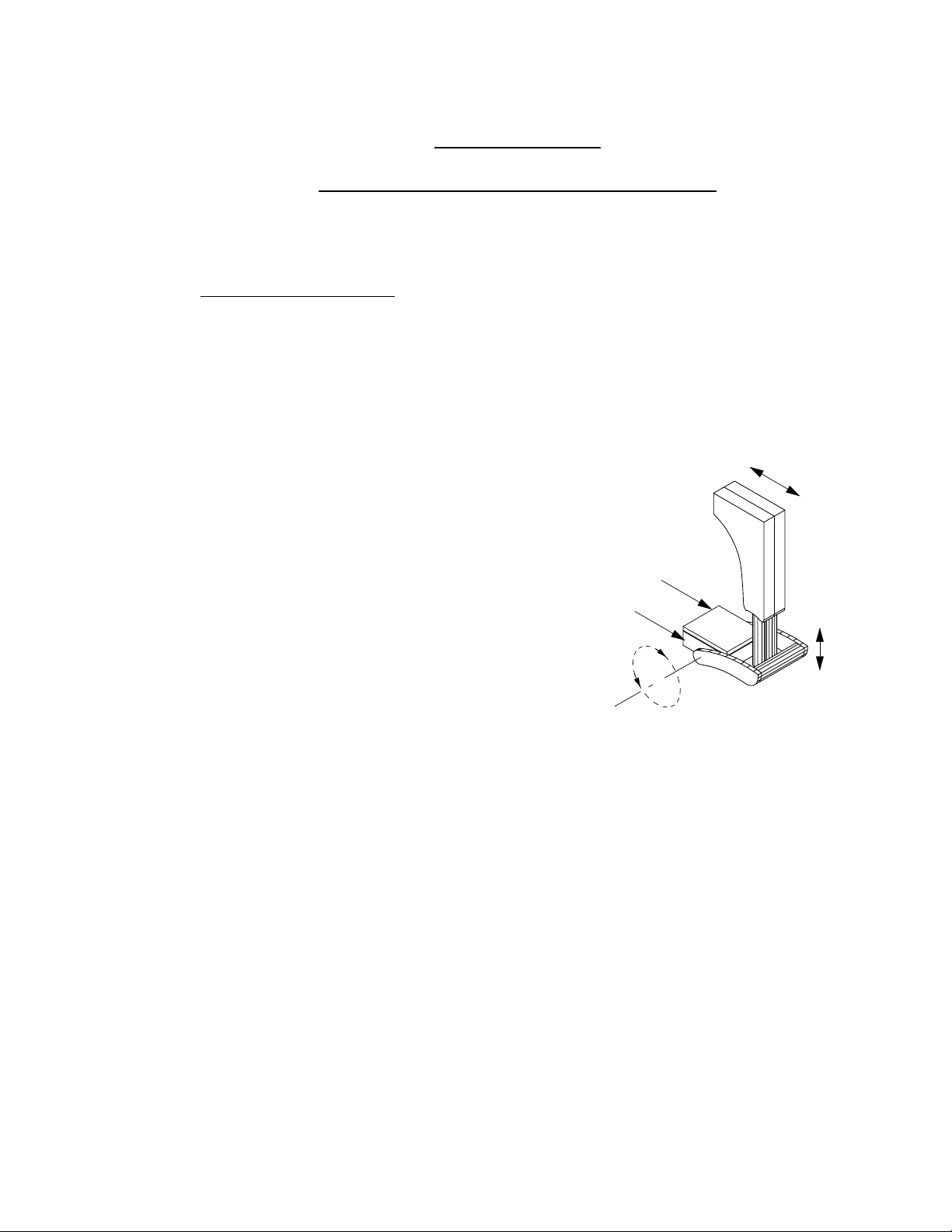
A carriage translates along the overhead frame
and supports two image-collecting detectors.
The detectors can move up and down, in and
out, and rotate around their own axis. This
allows the detectors to image patients from
above, below, or from the sides of a patient.
Prior to imaging a patient, nuclear medicine
technologists attach a pair of “collimators” on
the detectors. Collimators are 21" x 26" (53cm x
66cm) sheets of lead. Several different types of
collimators exist; collimators weigh between
110 and 260 lbs (50 and 118 kg).
When a pair of collimators are not on the detectors, technologists will store the
collimators in a floor-mounted, collimator exchanger on one side of the Skylight
frame.
The system also includes two “towers” containing electronic components: the PC
tower and the power tower.
The PC tower contains image processing and networking equipment.
The power tower contains an uninterruptible power supply (UPS) and other power
supplies.
Collimator
Detector
In/Out
Up/
Down
The PC tower, power tower, collimator exchanger and vanity covers fill one side of
the Skylight frame.
1-1
Page 4

Section 1: General Requirements
Clinical Operation
Although not shown in Figure 1-1, a desktop processing station (a PegBlade) must
be located outside the frame, but preferably in the same room. From the PegBlade,
physicians view and interpret images produced by the system.
Patients to be imaged by the Skylight system receive a small intravenous injection
of a gamma-ray-emitting radionuclide. The collimators contain a pattern of
gamma-ray admitting holes perpendicular to the imaging surface of the detectors.
The detectors sense the radiation that passes through holes in the collimators.
The detectors transmit electronic data to image processors in the PC tower. The
image processors produce images for physician interpretation on the PegBlade
processing station.
The Skylight system performs these types of clinical studies:
• Emission Computed Tomography (ECT) -- the carrriage remains in one
position while the detectors rotate around the patient’s torso. Image
processors produce a set of three dimensional tomographic images. The
images show radionuclide concentration in parallel slices of the patient’s
internal organs.
• Total Body -- the carrriage translates along the length of the patient (usually
head to toe). One detector scans above the patient table; the other scans
below patient table. The image processors produce two images (anterior and
posterior) showing radionuclide concentration in the patient’s skeleton and
other tissue.
• Static (Spot) or Dynamic -- the carriage and detectors remain fixed positions
near the patient. The system produces either a single image (static), or a
sequence of images (dynamic) showing the flow of radionuclide within the
patient over time.
1-2
Page 5
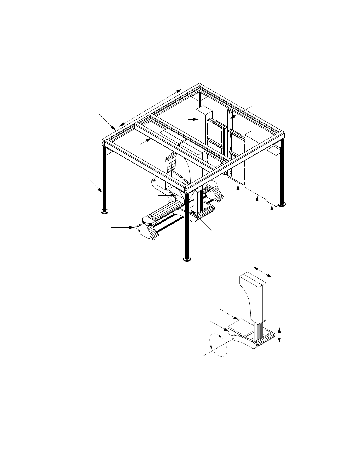
Frame
Frame
Support
Post
(1 of 4)
Carriage Motion
Carriage
Section 1: Room Requirements
Power
Tower
Exchanger
Support
Post
Detector #1
Patient Table
Note:
Covers around front posts and
filling all open spaces above
Power Tower, PC Tower and
Exchanger are not shown.
Detector #2
(see detail)
Collimator
Detector
Collimator
Exchanger
Vanity
Cover
PC
Tower
In/Out
Up/
Down
Detector #2 Detail
(Detector #1 is similar)
Figure 1-1. Skylight Camera System.
1-3
Page 6

Section 1: General Requirements
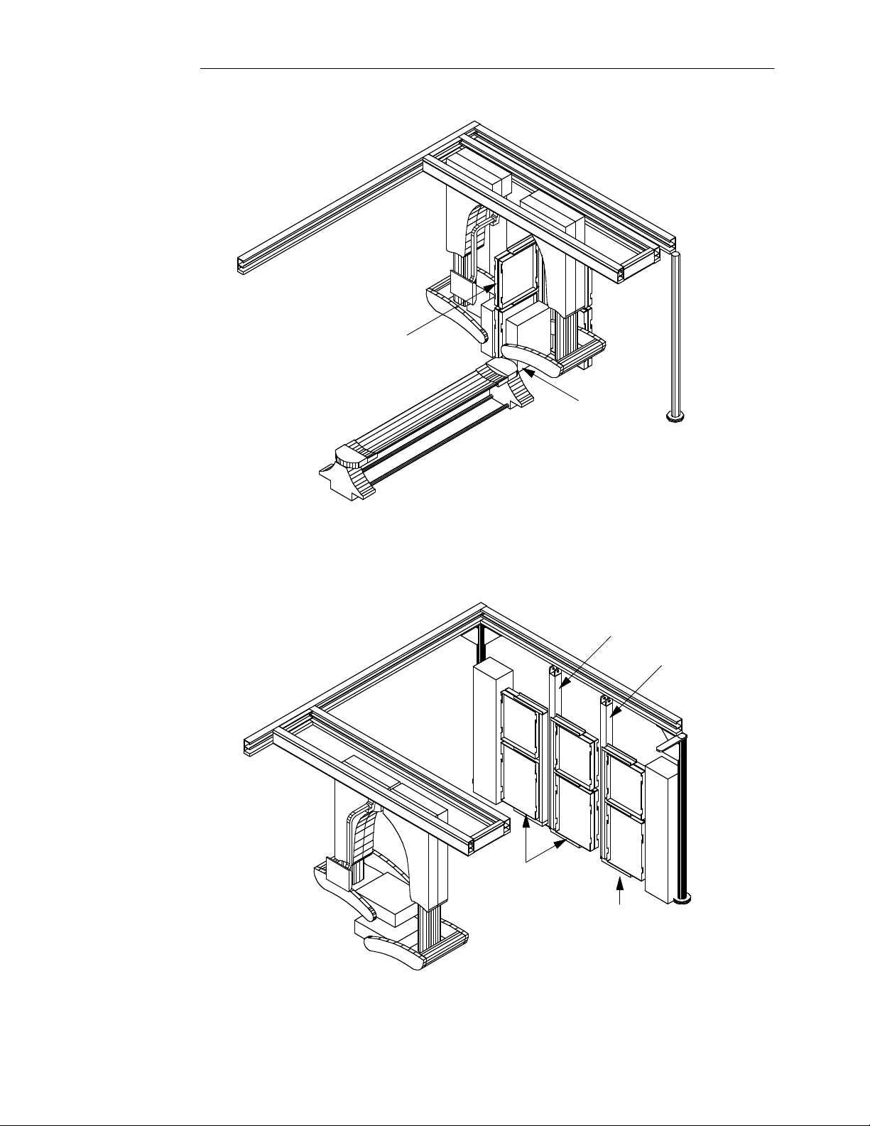
Collimator Exchanger
Technologists store collimators in vertical drawers of the collimator exchanger.
To transfer a collimator from an exchanger drawer to a detector, an operator will
swing the drawer 90° into the room, translate the carriage to the exchanger, and
move a detector next to a drawer as Figure 1-2 illustrates.
All Skylight systems come with a two-drawer collimator exchanger. That exchanger
will hold four pairs of collimators.
Customers may purchase a second, one-drawer collimator exchanger. The onedrawer exchanger will hold two more pairs of collimators. As Figure 1-3 shows, the
one-drawer collimator exchanger resides on the same wall as the two-drawer
exchanger.
Skylight Models
The Skylight system comes in one of four models:
• a 9 foot Skylight,
• a 9 foot California (seismic) Skylight,
• an 8 foot Skylight,
• an 8 foot California (seismic) Skylight.
The California (seismic) models have thicker-walled steel posts and three top braces
above the Skylight frame.
Vibration Specifications
Nuclear medicine cameras do not have floor vibration specifications. This is
because:
• image collection durations are long (10 - 300 seconds, or more) and floor
vibration durations are much smaller,
• vibrations are typically sinusoidal and, therefore, tend to cancel out, and
• the patient table and detector/gantry assemblies are both floor mounted and
tend to vibrate together.
1-4
Page 7
Section 1: General Requirements
Collimator exchanger drawer
swung 90° around exchanger
support post to transfer
collimators from or to Detectors
Detector #2 in position
to transfer a collimator
to or from the collimator
exchanger
Figure 1-2. Collimator Exchange Operation.
Exchanger
Support Post
(two drawer)
Two-Drawer
Collimator
Exchanger
One-Drawer
Collimator
Exchanger
(optional)
Exchanger
Support Post
(one drawer)
Figure 1-3. One-Drawer and Two-Drawer Collimator Exchangers
1-5
Page 8

Section 1: General Requirements
Power Requirements
The power requirements for a Skylight camera and PegBlade are as follows:
Skylight Camera PegBlade
Input Voltage: 208 - 240 V - dedicated 120 V
(International) 208 - 240 V - dedicated 220 V
Peak/Quiescent Current: 15 A / 4.8 A 5 A / NA
(International) 15 A / 4.8 A 2.5 A / NA
Phase: Single Phase Single Phase
Receptacle: Hardwired NEMA 5-15
Note: The Skylight camera includes a UPS and provides power to the detectors,
carriage, patient table, towers, acquisition terminal and collimator exchanger. An
optional cardiac gate can plug into a 115 volt receptacle on the patient table.
Air Conditioning Requirements
The system produces these heat loads:
Skylight System PegBlade PegBlade Monitor
5,653 BTU/hr 854 BTU/hr 544 BTU/hr
396 Cal/sec 60 Cal/sec 38 Cal/sec
1,656 watts 250 watts 159 watts
The camera room HVAC system must maintain the temperature between 60°- 75° F
(16° - 24° C) with less than 10° F (6° C) variation per hour. Humidity must be
between 20% - 75%.
These requirements must be met on a 24 hours per day, 7 days per week basis.
Magnetic Field Limitations
To avoid image quality and video monitor problems, the Skylight system must not
be in an area with a magnetic field greater than 1 Gauss.
Floor Levelness
The floor under the four Skylight frame posts, the collimator exchanger post(s) and
the patient table must all be at the same level ±1".
1-6
Page 9

Room Layout
Room Size Requirements
Section 2
9 Ft Skylight
W x D x H _ W x D x H _
Minimum Size 12'-6" x 14' x 9' 12'-6" x 14' x 8'
381cm x 427cm x 274cm 381cm x 427cm x 244cm
Recommended Size 16'-7" x 16'-10" x 9' 16'-7" x 16'-10" x 8'
505cm x 513cm x 274cm 505cm x 513cm x 244cm
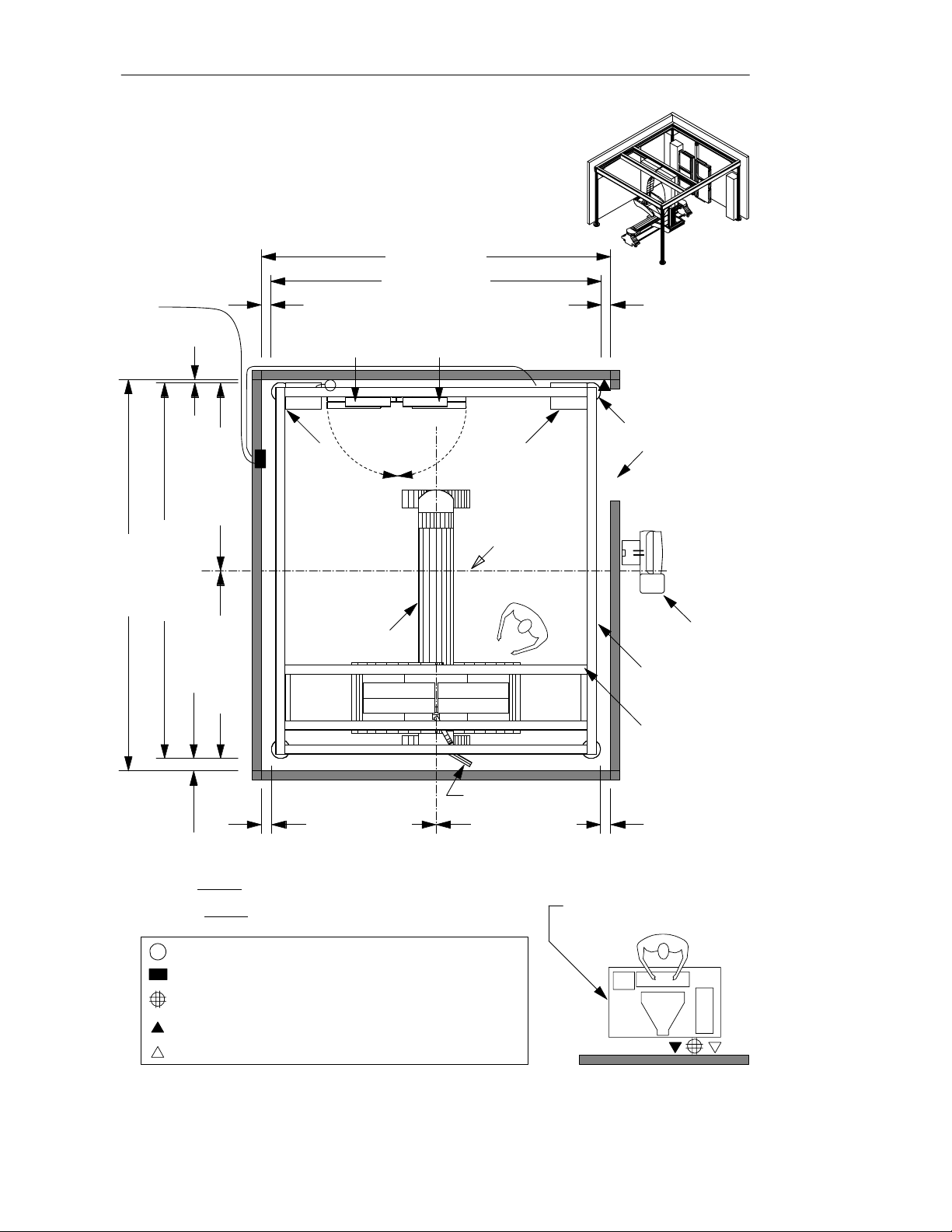
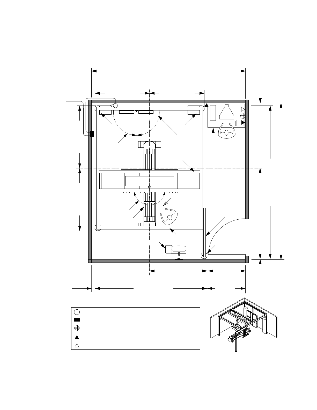
Figure. 2-1 illustrates a minimum room size. In such rooms, the site must provide a
separate, nearby room for the PegBlade processing station.
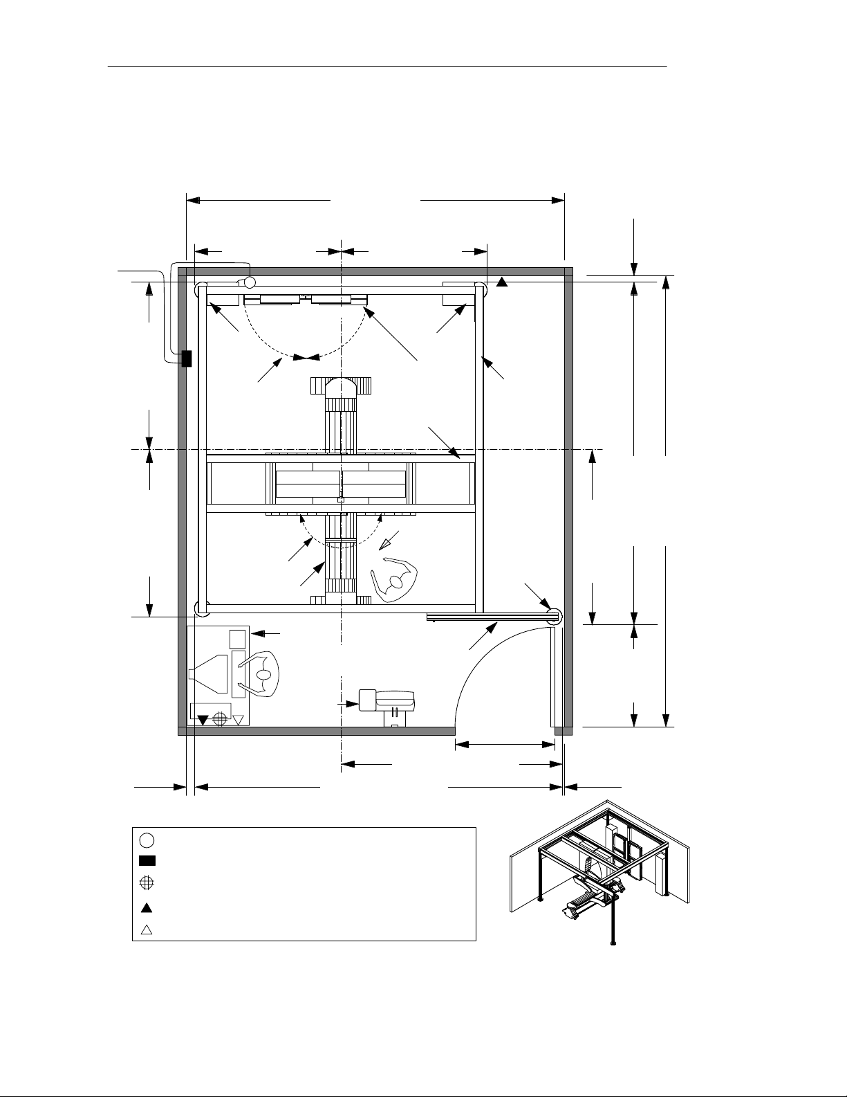
Figures 2-2 and 2-3 illustrates two recommended room sizes. Such rooms facilitate
patient access and technologist/physician convenience. To keep frame support posts
close to walls, Philips installers can extend one of the frame support posts from 20" to
36" in either the X or Y direction from the normal post position (Figure 2-2 & 2-3).
8 Ft Skylight
Equipment Sizes (9 ft and 8 ft Skylights)
W x D x H Wt
Skylight System1 11'-10" x 13'-6" see Fig 2-4 & 2-5 see pg 6-3
361cm x 411cm
Patient Table (minimum height) 2'-5" x 9'-6" x 1'-9" 320 lbs
74cm x 290cm x 53 145 kg
PegBlade CPU 18" x 18" x 5" 27 lb
(placed on customer’s desktop) 46cm x 46cm x 13cm 12 kg
PegBlade monitor 20" x 20" x 20" 69 lb
(placed on customer’s desktop) 51cm x 51cm x 51cm 32 kg
Codonics Printer (option) 17" x 21" x 12" 55 lbs
(placed on customer’s desktop) 43cm x 53cm x 30cm 25 kg
Important: Unless the floor is a reinforced concrete slab poured on grade, a licensed
structural engineer must
_______
1
At installation, Philips must lay a 11'-9.3" x 13'-5.4" rectangular metal drill template on the floor
(see Section3). There must be no objects at floor level to interfere with this template.
evaluate floor loading capacity. See Section 6.
2-1
Page 10
Section 2: Room Layout
Minimum (12'-6" x 14') Room Restrictions:
• Anchor plate for frame support posts placed 1"
from wall on side of Two-Drawer Collimator Exchanger
(instead of more desireable 3" placement),
• Acquisition Terminal placed outside of room,
• Processing Station placed in separate, nearby room,
• Display Panel and Boom tied in one position
(instead of allowing desireable free rotation of boom),
• Doors cannot swing into room.
12'-6" (381cm)
From Main
Electrical
Panel
1" (3cm)*
4" (10 cm)*
Collimator Exchanger:
Drawer #1 & Drawer #2
J
Power
Tower
11'-10" (361cm)
Two Drawer:
6'-9" (206 cm)
PC
Tower
Preferred side
of table for
patient access
4" (10 cm)*
Anchor Plate for Frame
Support Post (4 places)
Opening must be
curtain, sliding
door or pocket
door which does
not open into
Skylight frame.
C
L
Frame
14' (427cm)
13'-6" (411cm)
Patient Table
6'-9" (206 cm)
5'-11" (180 cm)
5"
(13 cm)*
* For a 9' Seismic Skylight,
all anchor plates must be at least 8" from all walls.
For an 8'
all anchor plates must be at least 6" from all walls.
J
Electrical Junction Box for hardwiring to 10' Skylight cord
Circuit Breaker, 208-240 VAC, 30 Amp, single phase
120 VAC, 15 Amp, NEMA 5-15
4" (10 cm)*
Seismic Skylight,
Touch Screen & Boom
(tied in one position)
5'-11" (180 cm)
C
L
Frame
Preferred side
of table for
operator
Acquisition
Terminal
Frame
Carriage
Scale: 1/4" = 1'
4" (10 cm)*
Processing Station:
Customer provided desktop;
Philips provided PegBlade CPU,
monitor & keyboard
Twin RJ-45 Ethernet Connector Box
Telephone line for modem
Figure 2-1. Skylight in Minimum Size Room and PegBlade in Separate Room.
2-2
Page 11
Scale: 1/4" = 1'
From Main
Electrical
Panel
5'-11" (180 cm)
J
Drawer #1 Drawer #2
Section 2: Room Layout
16'-7" (505cm)
3" (8 cm)
5'-11" (180 cm)
6'-9" (206 cm)
C
L
Frame
6'-9" (206 cm)
4" (10 cm)
Power
Tower
Movement of
Exchanger Drawers
Movement of Touch
Screen and Boom
Patient Table
Acquisition Terminal
Two-Drawer
Collimator
Exchanger
Carriage
6'-2" (188 cm)
C
Frame
L
12' -1" (368 cm)
PC
Tower
Preferred side of
table for patient
access
Preferred side
of table for
operator
Frame
Processing Station:
Customer provided
desktop.
Philips provided
PegBlade,
monitor/keyboard.
Frame "X"
Extension
(20" to 36"
post-centerline
to post-centerline)
"Moved" Frame
Support Post
48"
(122 cm)
49"
(124 cm)
16'-10" (513cm)
16'-6" (503cm) max
9'-9" (297 cm) max
1" (3 cm)
J
Electrical Junction Box for hardwiring to 10' Skylight cord
Circuit Breaker, 208-240 VAC, 30 Amp, Single Phase
115 VAC, 15 Amp, NEMA 5-15
Twin RJ-45 Ethernet Connector Box
Telephone line for modem
Figure 2-2. Skylight in Recommended Room #1.
2-3
Page 12
Scale: 1/4" = 1'
Section 2: Room Layout
From Main
Electrical
Panel
6'-9" (206 cm)
6'-9" (206 cm)
5'-11" (180 cm)
J
Drawer #1 Drawer #2
Power
Tower
Movement of
Exchanger Drawers
Movement of Touch
Screen and Boom
Patient Table
15'-2" (462cm)
Frame
C
L
5'-11" (180 cm)
Two-Drawer
Collimator
Exchanger
Carriage
Preferred side of
table for patient
access
PC
Tower
Preferred side
of table for
operator
Frame
"Moved"
Frame
Support
Post
3" (8 cm)
C
L
Frame
18'-1" (551cm)
13'-9" (420cm)
7'-0" (215cm)
Processing
Station:
Customer provided desktop.
Philips provided PegUltra,
monitor/keyboard.
Acquisition
Terminal
8'-10" (270 cm) max
14' -9" (450cm) max
4" (10 cm)
J
Electrical Junction Box for hardwiring to 10' Skylight cord
Circuit Breaker, 208-240 VAC, 30 Amp, Single Phase
115 VAC, 15 Amp, NEMA 5-15
Twin RJ-45 Ethernet Connector Box
Telephone line for modem
Figure 2-3. Skylight in Recommended Room #2.
Frame "Y"
Extension
(20" to 36"
post-center to
post-center)
4'-1"
(124 cm)
4'
(122 cm)
1" (3 cm)
2-4
Page 13
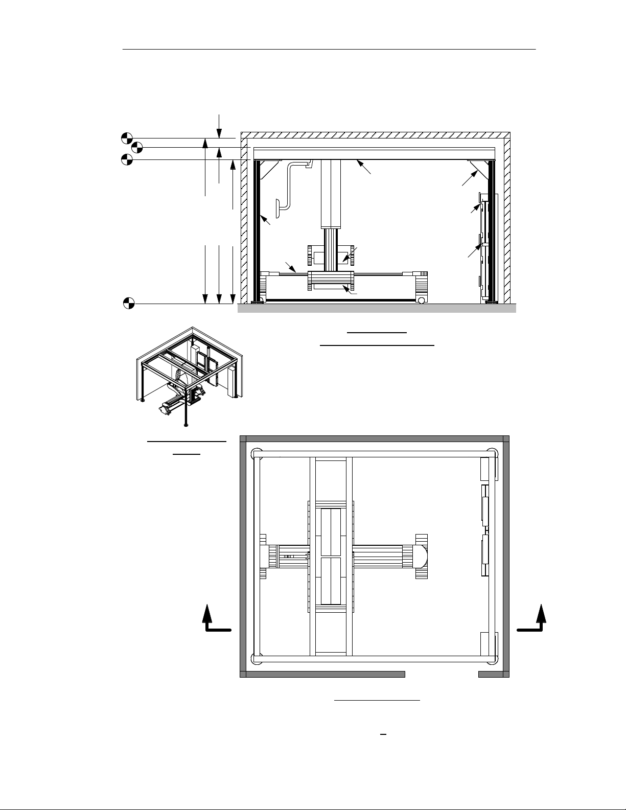
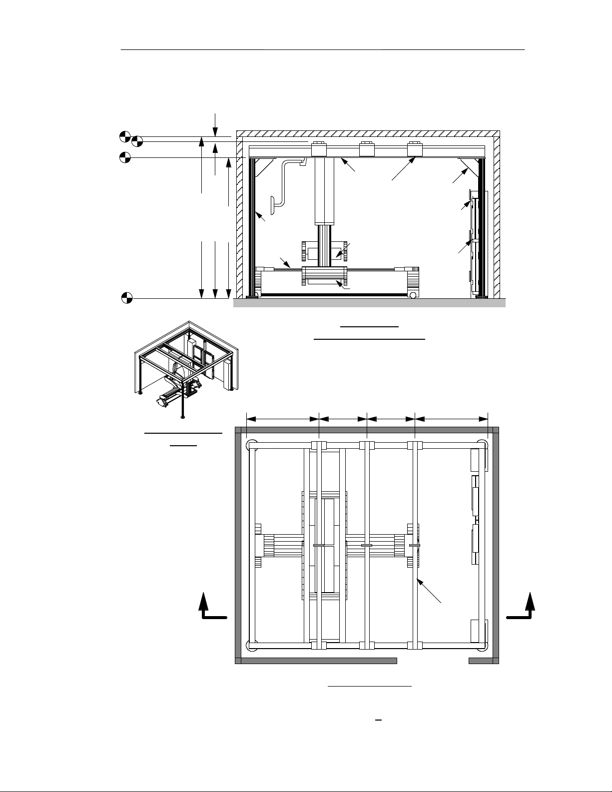
Finished Ceiling
Frame Top
Frame Bottom
Notes:
Post height is
adjustable
±1.11" to allow
for uneven
finish floor.
Some carriage
components
extend 1.5"
above frame.
Section 2: Room Layout
Worst case clearance = 108" - (103.86" + 1.11" + 1.50") = 108" - 106.47" = 1.53"
Frame
Gusset
Power Tower
Collimator
Exchanger
8'-7.86" ±1.11"
9' minimum
8' ±1.11"
Support
Post
Patient
Table
Detector
Finished Floor
Right Isometric
View
Detector
Section AA
Elevation (Side) View
Scale: 1/4" = 1'
A A
Plan (Top) View
Figure 2-4. Elevation Details, 9 ft Skylight
(non-California)
2-5
Page 14
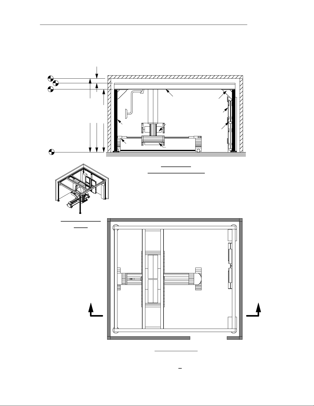
Finished Ceiling
Frame Top
Frame Bottom
Section 2: Room Layout
Worst case clearance = 96" - (91.86" + 1.11" + 1.50") = 96" - 94.47" = 1.53"
Notes:
Post height is
adjustable
±1.11" to allow
for uneven
finish floor.
Some carriage
components
extend 1.5"
above frame.
Finished Floor
Right Isometric
View
7'-7.86" ±1.11"
8' minimum
7' ±1.11"
Support
Post
Patient
Table
Frame
Power Tower
Detector
Detector
Section AA
Elevation (Side) View
Scale: 1/4" = 1'
Gusset
Collimator
Exchanger
A A
Plan (Top) View
Figure 2-5. Elevation Details, 8 ft Skylight
(non-California)
2-6
Page 15
Finished Ceiling
Frame Top
Frame Bottom
Notes:
Post height is
adjustable
±1.11" to allow
for uneven
finish floor.
Section 2: Room Layout
Worst case clearance = 108" - (106.74" + 1.11") = 108" - 107.85" = 0.15"
Frame
Gusset
Power Tower
Collimator
Exchanger
8'-10.74" ±1.11"
9' minimum
8' ±1.11"
Support
Post
Patient
Table
Seismic
Top Brace
(1 of 3)
Detector
Finished Floor
Right Isometric
View
Detector
Section AA
Elevation (Side) View
Scale: 1/4" = 1'
49"32"32"49"
A A
Seismic
Top Brace
(1 of 3)
Plan (Top) View
Figure 2-6. Elevation Details, 9 ft Skylight
(California Seismic)
2-7
Page 16

Finished Ceiling
Frame Top
Frame Bottom
Notes:
Post height is
adjustable
±1.11" to allow
for uneven
finish floor.
Finished Floor
Section 2: Room Layout
Worst case clearance = 96" - (94.74" + 1.11") = 96" - 95.85" = 0.15"
7'-10.74" ±1.11"
8' minimum
7' ±1.11"
Support
Post
Patient
Table
Frame
Seismic
Top Brace
(1 of 3)
Detector
Detector
Gusset
Power Tower
Collimator
Exchanger
Section AA
Elevation (Side) View
Right Isometric
View
A A
Scale: 1/4" = 1'
49"32"32"49"
Seismic
Top Brace
(1 of 3)
Plan (Top) View
Figure 2-7. Elevation Details, 8 ft Skylight
(California Seismic)
2-8
Page 17

Section 2: Room Layout
Maximum Detector Movement
To avoid collisions with the Skylight detector arms, the space in the movement
range shown below must be free of all non-Skylight objects (entrance door swings,
cabinetry, medical gas fixtures, etc.).
C
Carriage
in Collimator
Exchange
Position
L
Frame
11"
68"
Edge of
Frame
C
L
Frame
Carriage
over Patient's
Head
2"
60"
67" 67"
134"
Movement Range
Frame
C
L
70"
9"
2"
Edge of FrameEdge of Frame
42"
Movement
138"
Edge of
Frame
View
Movement Range
Front
View
Range
Top
Finished
Floor
Edge of Anchor Plate
of Frame Support Post
67"
134"
Movement Range
2-9
67"
18"
4"4"
Edge of Anchor Plate
of Frame Support Post
Page 18

;
;
;
;
;
;
;
;
;
;
;
;
;
;
;
;
;
;
;
;
;
;
;
;
;
;
;
;
;
;
;
;
;
;
;
;
;
;
;
;
;
;
;
;
;
;
;
;
;
;
;
;
;
;
;
Section 2: Room Layout
Wall-mounted Acquisition Terminal
The Acquisition Terminal consists of a flat screen monitor, keyboard and mouse.
On a wall near the Skylight frame, Philips installers will mount an electrical utility
box and a vertical rail. The rail supports the monitor, keyboard and mouse.
;
;
;
;
;
;
;
;
;
;
;
;
;
;
;
;
;
;
;
;
7" - 12"
;
;
;
;
;
;
;
;
;
;
;
;
;
;
;
;
;
6"
;
;
;
;
;
;
;
;
;
;
;
;
;
;
;
;
;
;
Top View
Mounting Rail
(Adac installed)
16"
Monitor
18"
5" min
Philips
Utility Box
(cable access
at bottom)
Raceway
Elevation View
9"9"9"
Monitor
Rail (2.5" wide)
2-10
Keyboard,
Mouse &
Tray
(Scale 1/2" = 1')
17"
Total
Weight of
Acquisition
Terminal
~30 lbs
(no scale)
Isometric View
Note:
Height of Monitor and
Keyboard/Mouse Tray
are adjustable along the
36" vertical rail.
1/4"-20 x 2.5"
Hollow Wall
Anchors
(qty = 8)
0.7"
11.5"
11.5"
36"
11.5"
Top of Utility Box
10"
Bottom of Utility Box
0.8"
1.5"
7"
1.5"
23.5"
(recommended)
Finished Floor
Monitor and
Keyboard/Mouse Tray
can swivel right or left
to the point of touching
the wall.
0
(Scale 1/2" = 1')
5"
5"
Page 19

Section 2: Room Layout
Signal and 110 VAC power cables come from the Skylight PC Tower to an
Philips-provided, wall-mounted utility box underneath the Acquisition Terminal.
Depending on customer preference, Philips installers will run these cables either in:
• an Philips-installed raceway (preferred), or
• a customer-installed conduit (optional).
Philips-installed Raceway. Philips installers will usually run 1.5" x 1" white
raceway from the Acquisition Terminal utility box, vertically up the wall and over
to the nearest point on the Skylight frame.
Raceway
Raceway
Elevation Front View
Philips
Utility
Box
Customer-installed Conduit. Customers not
wanting raceway must install 2" diameter conduit
from a flush-mounted customer junction box 9"
above the floor behind the PC Tower to another
flush-mounted customer junction box 18" above
the floor under the Philips Utility Box beneath the
Acquisition Terminal.
The maximum cable length from the PC Tower to
the Acquisition Terminal is 70 feet.
Raceway
Raceway
Elevation Side View
4" x 4" flush mounted
junction box with 1.5"
diameter grommeted hole
in front service plate
PC Tower
2" Conduit
Acquisition Terminal Placement. Philips has
optimized the Skylight system for the operator to
stand on the right side of the patient table (as
Acquisition
Terminal
viewed looking toward the collimator exchanger).
Therefore, if possible, it is best to mount the
Acquisition Terminal on the right side, or front
right side, of the patient table.
4" x 4" flush mounted
junction box with 1.5"
diameter grommeted hole
in front service plate
Weight of the Acquisition Terminal. The combined weight of the flat screen
monitor and other components of the Acquisition Terminal is about 30 pounds.
2-11
Page 20

Section 2: Room Layout
Touch Screen and Boom
The Skylight system includes a boom-mounted Touch Screen from which the
operator can control motions and other operations. The boom is mounted on, and
moves with, the Carriage.
For operator convenience, the boom is free to rotate about its attachment point on
the Carriage. The Touch Screen extends 13.6" beyond the frame when the operator
moves the Carriage to the non-Exchanger end of the Skylight frame. If the boom is
secured to the Carriage (which is not desireable except in small rooms such as shown
in Figure 2-1), the Touch Screen extends 3" from the frame.
13.6"
Touch
Screen
3"
(if boom tied)
A A
Boom
Touch
Screen
12.5"
Note:
Touch
Screen
height is
same for
both 8' & 9'
Skylights
55" 62"
Plan (Top) View
Finished Floor
Section AA
Elevation (Side) View
2-12
Page 21

Section 2: Room Layout
Cosmetic Covers
As a final step during installation, Philips installers will place covers over the front
Skylight frame support posts. Installers will also place covers over the open spaces
around and above the collimator exchanger and the PC and Power Towers.
Covers around
Collimator Exchanger
and PC/Power Towers
Front Frame
Support Post
Covers
Finished Floor
Front Frame
Support Post
Covers
Finished Floor
Elevation View (Front)
Elevation View (Side)
2-13
Page 22

Section 2: Room Layout
CAD Drawings
For the use of architects doing room layouts, drawings in a DWG format for the
Skylight system are downloadable from the following website:
http://apps1.medical.philips.com/documents
2-14
Page 23

Section 3
Anchor Details
Anchor Plan
Philips installers will locate and drill holes for
four 1/2" concrete anchors for each corner post
by placing a large metal drill template on the
floor.
The figures in this section illustrate the anchor
locations for Skylights with no frame
extension, X-extensions and Y-extensions.
(Section 2 discusses extensions.)
After installing the Skylight posts and frame, Philips installers will attach the
two-drawer collimator exchanger post to the frame and anchor it with four 3/8" flush
anchors. If the customer orders the optional one-drawer collimator exchanger,
installers will install an additional post in a similar manner.
Drill Template
13'-5.4"
11'-9.3"
Anchor Specifications
Philips installers will use these types of expansion anchors:
Manufacturer Model Diameter ICBO # Embedment Applicable Post
Hilti Kwik-Bolt II 1/2" 4627 3.50" Frame Support
Hilti HDI 3/8" - - Collimator Exchanger
California Seismic Information
Philips is in the process of obtaining “Pre-approval of Anchorage for Fixed Hospital
Equipment” for the Skylight system from the State of California Office of Statewide
Hospital Planning Department (OSHPD).
When the OSHPD documentation becomes available, customers may obtain a copy
from this website:
http://apps1.medical.philips.com/documents
Until OSHPD Pre-approval becomes available, Philips will assist customer architects
and structural engineers in obtaining site-specific OSHPD approval. To request
site-specific calculations call 408/468-3280.
3-1
Page 24

Mounting Assembly
for Two-Drawer
Collimator
Exchanger Post
4"
(see Fig 3-5)
Mounting Assembly
for Frame
Support Post
(4 places)
(see Fig 3-4)
C
L
Beam/Plate
C
L
Beam/Plate
4'-2" (127cm) 2'-9" (84cm)
5'-7" (170cm)
6'-5" (196cm)
Section 3: Anchor Details
C
L
Frame
1'-4.5"
1'-4.5"
(42cm)
(42cm)
Mounting L-Bracket (2) for
Optional One-Drawer
Collimator Exchanger Post
(see Fig 3-6)
C
L
Frame
C
L
C
L
6'-5" (196cm)
C
L
Beam/Plate
5'-7" (170cm)
11'-2" (340cm)
Note:
Anchor holes must not be drilled before installation.
Philips installers determine exact anchor locations:
- for Frame Support Posts using a drill template, and
- for Exchanger Posts after attaching posts to frame.
Scale: 1/4" = 1'
12'-10" 392cm)
4" (all 4 beams)
5'-7" (170cm)
Top View
Figure 3-1. Skylight Anchor Plan, No Frame Extension
3-2
Page 25

Mounting Assembly
for Two-Drawer
Collimator
Exchanger Post
(see Fig 3-5)
Mounting Assembly
for Frame
Support Post
(4 places)
(see Fig 3-4)
C
L
Beam/Plate
C
L
Beam/Plate
4"
6'-5" (196cm)
Section 3: Anchor Details
4'-2" (127cm) 2'-9" (84cm)
C
L
Frame
1'-4.5"
1'-4.5"
(42cm)
(42cm)
5'-7" (170cm)
Mounting L-Bracket (2) for
Optional One-Drawer
Collimator Exchanger Post
(see Fig 3-6)
4" (all 4 beams)
C
L
Frame
C
L
C
L
6'-5" (196cm)
C
L
Beam/Plate
Note:
Anchor holes must not be drilled before installation.
Installers determine exact anchor locations:
- for Frame Support Posts using a drill template, and
- for Exchanger Posts after attaching posts to frame.
5'-7" (170cm)
Top View
Scale: 1/4" = 1'
C
L
Plate
5'-10.9" (179.9 cm)
C
L
Beam
C
L
Extension/Plate
8'-1" to 9'-5"
(8'-1" shown)
20" to 36" (20" shown)
3.9"
(9.9cm)
Figure 3-2. Skylight Anchor Plan, X-Extension (long axis)
3-3
Page 26

Mounting Assembly
for Two-Drawer
Collimator
Exchanger Post
4"
(see Fig 3-5)
Mounting Assembly
for Frame
Support Post
(4 places)
(see Fig 3-4)
C
L
Beam/Plate
C
L
Beam/Plate
Section 3: Anchor Details
4'-2" (127cm)
2'-9" (84cm)
C
Frame
1'-4.5"
(42cm)
L
1'-4.5"
(42cm)
Mounting L-Bracket (2) for
Optional One-Drawer
Collimator Exchanger Post
(see Fig 3-6)
5'-7" (170cm)
4" (all 4 beams)
6'-5" (196cm)
C
L
Frame
C
L
6'-8.9"
C
L
(205cm)
6'-5" (196cm)
C
L
Beam/Plate
5'-7" (170cm)
7'-2" to 8'-6"
C
L
Extension/
Plate
3.9"
(9.9cm)
Top View
Scale: 1/4" = 1'
C
Plate
L
Note:
Anchor holes must not be drilled before installation.
Installers determine exact anchor locations:
- for Frame Support Posts using a drill template, and
- for Exchanger Posts after attaching post to frame.
Figure 3-3. Skylight Anchor Plan, Y-Extension (short axis)
3-4
Page 27

8" Dia.
1/2" Thick Steel
Leveling Plate of
Frame Support Post
C
L
Beam/Plate
6" Dia.
Anchor
Circle
Top
View
C
L
Beam/Plate
Section 3: Anchor Details
Note:
Although the non-seismic and
seismic posts are different, the
anchor hole patterns are identical.
8" Dia.
1/2" Thick Steel
4" Dia.
Frame
Support
Post
1/2" Dia.
Anchor
(4 places)
Leveling
Screws
(4 places)
Retainer Plate
C
L
Beam/Plate
6" Dia.
Anchor
Circle
Top
View
C
L
Beam/Plate
4" Dia.
Frame
Support
Post
1/2" Dia.
Anchor
(4 places)
Retainer
Screws
(4 places)
4" Dia.
Support
8" Dia.
1/2" Thick Steel
Leveling Plate of
Frame Support Post
Finish
Floor
1/2" Dia. Anchors
(Philips installed)
Elevation
View
Frame
Post
(4 places)
Non-Seismic
1/2" Dia.
Leveling
Screws
(4 places)
8" Dia.
1/2" Thick Steel
Anchor Plate
8" Dia.
1/2" Thick Steel
Retainer Plate
8" Dia.
3/4" Thick Steel
Anchor Plate
Elevation
Scale: 1" = 6"
Finish
Floor
View
4" Dia.
Frame
Support Post
Swivel
Shaft
1/2" Dia. Anchors
(Philips installed)
Seismic (California)
Retainer
Screws
(4 places)
Swivel
Shaft
Restraint
Wire
(4 places)
Figure 3-4. Mounting Assembly for Frame Support Post
(non-Seismic and Seismic)
3-5
Page 28

Section 3: Anchor Details
Section AA
Top
View
4" Dia.
Swivel
Mount
Elevation
View
4" Dia.
Swivel
Mount
3/8" Dia.
Anchor
Screw
(4 places)
Post/Plate
(4" x 4" sq)
A
Finish
Floor
3/8" Dia.
Anchor Inserts
(Philips installed)
(4 places)
C
Post
(4" x 4" sq)
not shown
C
L
Beam/Plate
3" Dia.
Anchor
Circle
L
Post
A
Height
Adjust
Screw
Note:
Installers determine the exact anchor locations so the Post will be vertical.
Scale: 1" = 6"
Figure 3-5. Mounting Assembly for Two-Drawer Collimator Exchanger Post
3-6
Page 29

Section 3: Anchor Details
Top View
4"
L-Bracket
3/8" Thick
(2 places)
L-Bracket
7"x4"x3/8"
(2)
3/8" Dia.
Anchor
Screw
(4 places)
5-1/4"
C
10-1/2"
Post
(2.5"x4"x3/6" Tube)
(not shown)
7"
L
3-1/2"
Post
2"
C
L
Beam
1/2"
Iso View
(not to scale)
Finish
Floor
Anchor Inserts
Elevation View
Note:
Installers suspend the Optional Collimator Exchanger Post from the
Skylight Frame. Because the screws attaching the Post to the L-Brackets
are in slotted holes, there is no significant vertical load on the floor.
Installers determine the exact anchor locations so the Post will be vertical.
(Philips installed)
(4 places)
Scale: 1" = 6"
Figure 3-6. Mounting L-Brackets for Optional Collimator Exchanger Post
3-7
Page 30

Section 3: Anchor Details
3-8
Page 31

Section 4
Networking
Networking Situations
There are two general types of Skylight networking situations:
1. Single Camera/Computer. In a single camera/computer installation, the
Skylight camera, the PegBlade computer, and, perhaps, a printer must be
networked together. There is no need to connect to networking devices outside
of the camera room.
The customer is responsible for providing one twin RJ-45 connection box near
the PC tower and one near the PegBlade. The customer also needs to run Cat 5
cables in the walls, ceilings, or floors between the connection boxes. The
upper half of Figure 4-1 illustrates this.
If the customer does not provide the connection boxes and does not run the
Cat 5 cables in the walls, Philips will run those cables along the floor. That
may be unsightly if the connection boxes are far apart.
2. Multiple Camera/Computer. In a multiple camera/computer installation, the
Skylight camera, the PegBlade computer, and, perhaps, a printer may be
networked to other networking devices. These other networking devices could
be another Philips network, a hospital network, or other networking devices
such as a network printer or a network viewing station as illustrated below.
Vertex1
Classic
Epic
adac
Peg 15
(master)
adac1
Peg 20
(client1)
ADAC
10/100
Switch
atlas1
Atlas
Acquisition
Forte
Acquisition
Camera
Central
Connectivity
Point
Codonics
Network
Printer
Skylight1
Remote
PegX/PegU
Cluster
WebView
on
Home PC
(via PPP modem)
adac3
PegUltra 60
(client3)
Vertex1
Classic
Epic
Peg2Peg
Transfer via
Hospital WAN
(master)
(client1)
adac
Peg 15
adac1
Peg 20
Hospital Switch
w/filtering VLAN
port for ADAC LAN
ADAC
10/100
Switch
atlas1
Atlas
Acquisition
Forte
Acquisition
Camera
GE
PACS
Server
Codonics
Network
Printer
Skylight1
other mfr
nuc med
camera
NUMA
data
converter
In a multiple camera/computer situation, the customer must install the twin
RJ-45 connector boxes near the PC tower and near the PegBlade. They must
also run Cat 5 cables from the two connector boxes to a central connectivity
point before Philips can network to other devices. The bottom half of Figure
4-1 illustrates this requirement.
4-1
Page 32

Section 4: Networking
PC
Tower
(with
10/100
switch)
Two Cat 5
Straight
Thru
Cables
(if hospital
ITS group
requires
meeting in
central room,
cables should
be jumpered
at patch panel.)
Two Cat 5
Straight
Thru
Cables
(one is
spare)
To central
connectivity
point
(10/100
switch)
Single
Camera/Computer
PegBlade
Processing Station
(with possible printer)
PC
Tower
Multiple
Camera/Computer
To central
connectivity
point
(10/100
switch)
Two Cat 5
Straight Thru
Cables (one is
spare, unless
processing station
includes a printer)
Figure 4-1. Single and Multiple Camera/Computer Networks.
PegBlade
Processing Station
(with possible printer)
4-2
Twin RJ-45 Connector Box
(9" above floor)
Page 33

Section 5
Shipping Information
Shipping Containers
The shipping crate and pallet sizes for Skylight components appear below.
Weights
Component W x D x H Normal Seismic Quantity
Detectors: 61" x 40" x 70" 1,600 lbs 1,600 lbs 2
155 x 102 x 178 cm 726 kg 726 kg
Posts: 100" x 44" x 12" 700 lbs 1,100 lbs 1
(all 4 pieces) 254 x 112 x 30 cm 318 kg 499 kg
Exchanger: 101" x 37" x 12" 700 lbs 700 lbs 1
257 x 94 x 30 cm 318 kg 318 kg
Carriage: 137" x 43" x 14" 600 lbs 600 lbs 1
348 x 109 x 36 cm 272 kg 272 kg
Frame: 163" x 27" x 12" 1,000 lbs 1,000 lbs 1
(all 4 pieces) 414 x 69 x 30 cm 454 kg 454 kg
Table: 120" x 37" x 30" 400 lbs 400 lbs 1
305 x 94 x 76 cm 181 kg 181 kg
Towers: 78" x 41" x 26" 400 lbs 400 lbs 1
198 x 104 x 66 cm 181 kg 181 kg
Covers: 78" x 41" x 26" 300 lbs 300 lbs 1
198 x 104 x 66 cm 136 kg 136 kg
Installers can remove the two largest components (Carriage and Frame) from their
shipping crates to facilitate moving those components within a hospital. Carriage
and Frame dimensions without shipping crates appear on the next page.
5-1
Page 34

Section 5: Shipping Information
Largest Components without Shipping Containers
The Carriage and Frame sizes (without shipping crates) appear below:
Weights
Component W x D x H Normal Seismic Quantity
Carriage: 130" x 39" x 8" 495 lbs 495 lbs 1
330 x 99 x 20 cm 225 kg 225 kg
Frame: 158" x 8" x 4" 173 lbs 173 lbs 4
(1 of 4 pieces) 401 x 20 x 10 cm 78 kg 78 kg
Although it takes several hours, installers can disassemble the Carriage into
components no larger than about 130" x 4" x 8", and reassemble the Carriage in the
camera room.
5-2
Page 35

Section 6
Floor Loading
General Floor Loading Information
Unless the floor is a reinforced concrete slab poured on grade, a customer’s licensed
structural engineer must evaluate floor loading capacity using the data in this section.
The weight of the Skylight frame, carriage, detectors and collimators rests on the
floor support posts and the two-drawer collimator exchanger post (see Section 3).
This section describes the floor loads in a minimum sized room (see Section 2), and
within the frame (footprint) of the Skylight. It also describes the point loads.
Floor loads and point loads depend on the type and quantity of collimators a
customer purchases. This section contains calculations for a (1) minimum set, (2) a
typical set, and (3) a worst case set of collimators.
When collimator pairs are not on the detectors, operators will store collimator pairs
in one of two types of collimator exchangers:
• a two-drawer collimator exchanger (holds up to four pairs of collimators), and
• a one-drawer collimator exchanger (holds up to two pairs of collimators).
The one-drawer collimator exchanger is optional. Customers will purchase that
option only if they purchase more than four collimator pairs (which is uncommon).
Below is a list of collimator types and weights:
LEGP = 110 lbs MEGP = 218 lbs
LEHR = 114 lbs HEGP = 235 lbs
VXGP = 110 lbs HEHR = 240 lbs (infrequently sold)
VXHR = 119 lbs Pinhole = 260 lbs
VXUR = 126 lbs
Collimators come in pairs, except the Pinhole which comes as a single collimator.
Seismic Information
Section 3 describes anchorage and state of California seismic approval information.
Seismic and non-seismic Skylight frames have different weights. Both weights are
shown in this section. This document, however, does not describe seismic force
reactions; Philips site-specific and pre-approval documents describe those reactions.
Both the seismic and non-seismic Skylight frames come in 8 ft. and 9 ft. heights.
However, the weight difference between 8 ft. and 9 ft. Skylights is not significant.
This section shows only 9 ft. weights for seismic and non-seismic frames.
6-1
Page 36

Section 6: Floor Loading
“Room” Floor Loading
The calculations below assume a minimum sized room with two technologists, a
patient and a room containing only Philips equipment.
1. Minimum Set of Collimators
Components Non-seismic Seismic
Wt (lbs) Wt (lbs)
Skylight Frame & Detectors 4,212 5,023
UPS Batteries 160 160
PC Tower 112 112
Power Tower 220 220
Exchanger w/2 Drawers 552 552
Collimators on Detectors:
VXGP (2 x 110) 220 220
Collimators on 2 Drwr Exch:
None 0 0
Patient Table 320 320
Patient 400 400
Technologists (2 x 200) 400 400
Total 6,596 7,407
Room Floor Load = 6,596÷175 7,407÷175
= 38 lbs/ft
2
42 lbs/ft
Area
Room = 12.5' x 14' = 175 sq ft
12.5'
14'
2
2. Typical Set of Collimators
Components Non-seismic Seismic
Wt (lbs) Wt (lbs)
Skylight Frame & Detectors 4,212 5,023
UPS Batteries 160 160
PC Tower 112 112
Power Tower 220 220
Exchanger w/2 Drawers 552 552
Collimators on Detectors:
VXGP (2 x 110) 220 220
Collimators on 2 Drwr Exch:
MEGP (2 x 218) 436 436
HEGP (2 x 235) 470 470
LEGP (2 x 110) 220 220
Patient Table 320 320
Patient 400 400
Technologists (2 x 200) 400 400
Total 7,722 8,533
Room Floor Load = 7,722÷175 8,533÷175
= 44 lbs/ft
2
49 lbs/ft
3. Worst Case Set of Collimators
Components Non-seismic Seismic
Wt (lbs) Wt (lbs)
Skylight Frame & Detectors 4,212 5,023
UPS Batteries 160 160
PC Tower 112 112
Power Tower 220 220
Exchanger w/2 Drawers 552 552
Collimators on Detectors:
VXGP (2 x 110) 220 220
Collimators on 2 Drwr Exch:
MEGP (2 x 218) 436 436
HEGP (2 x 235) 470 470
Pinhole 260 260
Exchanger w/1 drawer 281 281
Collimators on 1 Drw Exch:
LEGP (2 x 110) 220 220
LEHR (2 x 114) 228 228
Patient Table 320 320
Patient 400 400
Technologists (2 x 200) 400 400
Total 8,491 9,302
2
Room Floor Load = 8,491÷175 9,302÷175
= 49 lbs/ft
2
53 lbs/ft
2
6-2
Page 37

Sectin 6: Floor Loading
“Frame” Floor Loading
The calculations below examine only the floor loads of the Philips equipment
within the area bounded by the Skylight frame (footprint).
1. Minimum Set of Collimators
Components Non-seismic Seismic
Wt (lbs) Wt (lbs)
Skylight Frame & Detectors 4,212 5,023
UPS Batteries 160 160
PC Tower 112 112
Power Tower 220 220
Exchanger w/2 Drawers 552 552
Collimators on Detectors:
VXGP (2 x 110) 220 220
Collimators on 2 Drwr Exch:
None 0 0
Patient Table 320 320
Total 5,796 6,607
Room Floor Load = 5,796÷160 6,607÷160
= 36 lbs/ft
2
41 lbs/ft
Area
Frame = 11.83' x 13.5' = 160 sq ft
11.8'
13.5'
2
2. Typical Set of Collimators
Components Non-seismic Seismic
Wt (lbs) Wt (lbs)
Skylight Frame & Detectors 4,212 5,023
UPS Batteries 160 160
PC Tower 112 112
Power Tower 220 220
Exchanger w/2 Drawers 552 552
Collimators on Detectors:
VXGP (2 x 110) 220 220
Collimators on 2 Drwr Exch:
MEGP (2 x 218) 436 436
HEGP (2 x 235) 470 470
LEGP (2 x 110) 220 220
Patient Table 320 320
Total 6,922 7,733
Room Floor Load = 6,922÷160 7,733÷160
= 43 lbs/ft
2
48 lbs/ft
3. Worst Case Set of Collimators
Components Non-seismic Seismic
Wt (lbs) Wt (lbs)
Skylight Frame & Detectors 4,212 5,023
UPS Batteries 160 160
PC Tower 112 112
Power Tower 220 220
Exchanger w/2 Drawers 552 552
Collimators on Detectors:
VXGP (2 x 110) 220 220
Collimators on 2 Drwr Exch:
MEGP (2 x 218) 436 436
HEGP (2 x 235) 470 470
Pinhole 260 260
Exchanger w/1 drawer 281 281
Collimators on 1 Drw Exch:
LEGP (2 x 110) 220 220
LEHR (2 x 114) 228 228
Patient Table 320 320
Total 7,691 8,502
2
Room Floor Load = 7,691÷160 8,502÷160
= 48 lbs/ft
2
53 lbs/ft
2
6-3
Page 38

Section 6: Floor Loading
Carriage, Frame and Detector Weights
The illustrations below show five different cases of extreme carriage and detector
positions which affect the point loads that appear later in this section.
1. Carriage in
Exchanger Side
Frame
Weights
Carriage
Frame
Support
Post
(1 of 4)
Detector #1
R4
R2
Detector #2
R1
Object Weight (lbs) Weight (lbs)
Non-Seismic Seismic
Frame, Posts, Batteries 1,377 2,188
Carriage 495 495
Detectors (both) 2,500 2,500
(w/o collimators)
R3
2. Carriage Near Exchanger, Detectors Near R1 3. Carriage Near Exchanger, Detectors Near R2
R2
R4
R1
R4
R2
R1
R3
R3
4. Carriage Opposite Exchanger, Detectors Near R3 5. Carriage Opposite Exchanger, DetectorsNear R4
R2
R4
R3
R1
R4
R2
R1
R3
6-4
Page 39

Sectin 6: Floor Loading
Collimator Exchanger Weights
The loads on each collimator exchanger post are a function of the number and type
of collimators that a customer purchases.
The load on the two-drawer collimator exchanger appears on R6.
The optional one-drawer collimator exchanger post (R5) hangs from the Skylight
frame; 2/3 of its weight affects the load on R1 and 1/3 of its weight affects the load
on R2.
Post for the
two-drawer
collimator exchanger
Post for the optional
one-drawer
collimator exchanger
R2
R6
R5
R1
For clarity in this drawing, the
carriage, detectors and collimator
exchangers are not shown. (See
Section 1, Figure 1-3 for details.)
Minimum Weights on Two-Drawer Collimator Exchanger
_ Post_ Exchanger (lbs) Collimators Load Calculation on R6 (lbs)
R6 552 VGXP (2) 552+220 = 772
Typical Weights on Two-Drawer Collimator Exchanger
_ Post_ Exchanger (lbs) Collimators Load Calculation on R6 (lbs)
R6 552 VGXP (2), MEGP (2), 552+220+436+470+220=1,898
HEGP (2), LEGP (2)
Worst Case Weights on both Collimator Exchangers
Load (lbs)
_ Post_ Exchanger (lbs) Typical Collimators Load Calculation (lbs) R6 R1 R2
R6 552 VGXP (2), MEGP (2), 552+220+436+470+260= 1,938 1,938
(two drawer)
R5 281 LEGP (2), LEHR (2) 281+220+228=729 457 272
(one drawer)
(optional)
HEGP (2), Pinhole (1)
(2/3 R5) (1/3 R5)
6-5
Page 40

Section 6: Floor Loading
Point Loading with Minimum Collimators
The numbers below and the next page illustrate the total loads on all four frame
support posts (R1, R2, R3 & R4) and the two-drawer collimator exchanger post (R6)
assuming the customer only purchases one pair of VXGP collimators.
The point loads change as the VXGP collimator pairs move from the detectors to the
two-drawer collimator exchanger.
Non-seismic Skylight
Carriage Detectors Collimators on Point Loads (lbs)
Case Position Position Detectors Exchanger R1 R2 R3 R4 R6
1a In Center In center VXGP none 1,188 1,188 1,108 1,108 552
1b In Center In center none VXGP 1,133 1,133 1,053 1,053 772
2a Near Exchanger Near R1 VXGP none 2,135 1,347 627 482 552
2b Near Exchanger Near R1 none VXGP 2,010 1,286 604 470 772
3a Near Exchanger Near R2 VXGP none 1,347 2,135 482 627 552
3b Near Exchanger Near R2 none VXGP 1,286 2,010 470 604 772
4a Opposite Exchanger Near R3 VXGP none 707 562 2,055 1,267 552
4b Opposite Exchanger Near R3 none VXGP 684 550 1,930 1,206 772
5a Opposite Exchanger Near R4 VXGP none 562 707 1,267 2,055 552
5b Opposite Exchanger Near R4 none VXGP 550 684 1,206 1,930 772
The largest point load in the above situation is 2,135 lbs.
6-6
Page 41

Sectin 6: Floor Loading
Seismic Skylight
Carriage Detectors Collimators on Point Loads (lbs)
Case Position Position Detectors Exchanger R1 R2 R3 R4 R6
1a In Center In center VXGP none 1,391 1,391 1,311 1,311 552
1b In Center In center none VXGP 1,336 1,336 1,256 1,256 772
2a Near Exchanger Near R1 VXGP none 2,338 1,550 830 685 552
2b Near Exchanger Near R1 none VXGP 2,213 1,489 807 673 772
3a Near Exchanger Near R2 VXGP none 1,550 2,338 685 830 552
3b Near Exchanger Near R2 none VXGP 1,489 2,213 673 807 772
4a Opposite Exchanger Near R3 VXGP none 910 765 2,258 1,470 552
4b Opposite Exchanger Near R3 none VXGP 887 753 2,133 1,409 772
5a Opposite Exchanger Near R4 VXGP none 765 910 1,470 2,258 552
5b Opposite Exchanger Near R4 none VXGP 753 887 1,409 2,133 772
The largest point load in the above situation is 2,338 lbs.
6-7
Page 42

Section 6: Floor Loading
Point Loading with Typical Collimators
The numbers below and the next page illustrate the total loads on all four frame
support posts and the two-drawer collimator exchanger post (R6) assuming the
customer purchases pairs of VXGP, MEGP, HEGP and LEGP collimators.
The point loads change as the HEGP collimator pairs move from the detectors to the
two-drawer collimator exchanger.
Non-seismic Skylight
Carriage Detector Collimators on Point Loads (lbs)
Case Position Positions Detectors Exchanger R1 R2 R3 R4 R6
1a In Center In center HEGP MEGP, 1,250 1,250 1,170 1,170 1,428
VXGP, LEGP
1b In Center In center none VXGP,MEGP 1,133 1,133 1,053 1,053 1,898
HEGP, LEGP
2a Near Exchanger Near R1 HEGP MEGP, 2,277 1,416 653 495 1,428
VXGP, LEGP
2b Near Exchanger Near R1 none VXGP,MEGP 2,010 1,286 604 470 1,898
HEGP, LEGP
3a Near Exchanger Near R2 HEGP MEGP, 1,416 2,277 495 653 1,428
VXGP, LEGP
3b Near Exchanger Near R2 none VXGP,MEGP 1,286 2,010 470 604 1,898
HEGP, LEGP
4a Opposite Exchanger Near R3 HEGP MEGP, 733 575 2,197 1,336 1,428
VXGP, LEGP
4b Opposite Exchanger Near R3 none VXGP,MEGP 684 550 1,930 1,206 1,898
HEGP, LEGP
5a Opposite Exchanger Near R4 HEGP MEGP, 575 733 1,336 2,197 1,428
VXGP, LEGP
5b Opposite Exchanger Near R4 none VXGP,MEGP 550 684 1,206 1,930 1,898
HEGP, LEGP
The largest point load in the above situation is 2,277 lbs.
6-8
Page 43

Sectin 6: Floor Loading
Seismic Skylight
Carriage Detector Collimators on Point Loads (lbs)
Case Position Positions Detectors Exchanger R1 R2 R3 R4 R6
1a In Center In center HEGP MEGP, 1,453 1,453 1,373 1,373 1,428
VXGP, LEGP
1b In Center In center none VXGP,MEGP 1,336 1,336 1,256 1,256 1,898
HEGP, LEGP
2a Near Exchanger Near R1 HEGP MEGP, 2,480 1,619 856 698 1,428
VXGP, LEGP
2b Near Exchanger Near R1 none VXGP,MEGP 2,213 1,489 807 673 1,898
HEGP, LEGP
3a Near Exchanger Near R2 HEGP MEGP, 1,619 2,480 698 856 1,428
VXGP, LEGP
3b Near Exchanger Near R2 none VXGP,MEGP 1,489 2,213 673 807 1,898
HEGP, LEGP
4a Opposite Exchanger Near R3 HEGP MEGP, 936 778 2,400 1,539 1,428
VXGP, LEGP
4b Opposite Exchanger Near R3 none VXGP,MEGP 887 753 2,133 1,409 1,898
HEGP, LEGP
5a Opposite Exchanger Near R4 HEGP MEGP, 778 936 1,539 2,400 1,428
VXGP, LEGP
5b Opposite Exchanger Near R4 none VXGP,MEGP 753 887 1,409 2,133 1,898
HEGP, LEGP
The largest point load in the above situation is 2,480 lbs.
6-9
Page 44

Section 6: Floor Loading
Point Loading with Worst Case Collimators (uncommon)
The numbers below and the next page illustrate the total loads on all four frame
support posts and the two-drawer collimator exchanger post (R6) assuming a pin hole
collimator and pairs of LEHR, VXGP, MEGP, HEGP and LEGP collimators.
The LEHR and LEGP cxollimators will be on the optional one-drawer collimator
exchanger post; that post hangs from the frame, exerts no significant load on its post,
but adds load to posts R1 and R2. The other collimators put loads on R6.
Non-seismic Skylight
Carriage Detector Collimators on Point Loads (lbs)
Case Position Positions Detectors Exchangers R1 R2 R3 R4 R6
1a In Center In center HEGP MEGP, 1,736 1,493 1,170 1,170 1,468
VXGP, Pinhole
LEGP,LEHR
1b In Center In center none VXGP,MEGP 1,619 1,376 1,053 1,053 1,938
HEGP,Pinhole
LEGP,LEHR
2a Near Exchanger Near R1 HEGP MEGP, 2,763 1,659 653 495 1,468
VXGP,Pinhole
LEGP,LEHR
2b Near Exchanger Near R1 none VXGP,MEGP 2,496 1,529 604 470 1,938
HEGP, Pinhole
LEGP,LEHR
3a Near Exchanger Near R2 HEGP MEGP, 1,902 2,520 495 653 1,468
VXGP,Pinhole
LEGP,LEHR
3b Near Exchanger Near R2 none VXGP,MEGP 1,772 2,253 470 604 1,938
HEGP,Pinhole
LEGP,LEHR
4a Opposite Exchanger Near R3 HEGP MEGP, 1,219 818 2,197 1,336 1,468
VXGP,Pinhole
LEGP,LEHR
4b Opposite Exchanger Near R3 none VXGP,MEGP 1,170 793 1,930 1,206 1,938
HEGP,Pinhole
LEGP,LEHR
5a Opposite Exchanger Near R4 HEGP MEGP, 1,061 976 1,336 2,197 1,468
VXGP,Pinhole
LEGP,LEHR
5b Opposite Exchanger Near R4 none VXGP,MEGP 1,036 927 1,206 1,930 1,938
HEGP,Pinhole
LEGP,LEHR
The largest point load in the above situation is 2,763 lbs.
6-10
Page 45

Sectin 6: Floor Loading
Seismic Skylight
Carriage Detector Collimators on Point Loads (lbs)
Case Position Positions Detectors Exchanger R1 R2 R3 R4 R6
1a In Center In center HEGP MEGP, 1,939 1,696 1,373 1,373 1,468
VXGP, Pinhole
LEGP,LEHR
1b In Center In center none VXGP,MEGP 1,822 1,579 1,256 1,256 1,938
HEGP,Pinhole
LEGP,LEHR
2a Near Exchanger Near R1 HEGP MEGP, 2,966 1,862 856 698 1,468
VXGP,Pinhole
LEGP,LEHR
2b Near Exchanger Near R1 none VXGP,MEGP 2,699 1,732 807 673 1,938
HEGP, Pinhole
LEGP,LEHR
3a Near Exchanger Near R2 HEGP MEGP, 2,105 2,723 698 856 1,468
VXGP,Pinhole
LEGP,LEHR
3b Near Exchanger Near R2 none VXGP,MEGP 1,975 2,456 673 807 1,938
HEGP,Pinhole
LEGP,LEHR
4a Opposite Exchanger Near R3 HEGP MEGP, 1,422 1,021 2,400 1,539 1,468
VXGP,Pinhole
LEGP,LEHR
4b Opposite Exchanger Near R3 none VXGP,MEGP 1,373 996 2,133 1,409 1,938
HEGP,Pinhole
LEGP,LEHR
5a Opposite Exchanger Near R4 HEGP MEGP, 1,264 1,179 1,539 2,400 1,468
VXGP,Pinhole
LEGP,LEHR
5b Opposite Exchanger Near R4 none VXGP,MEGP 1,239 1,130 1,409 2,133 1,938
HEGP,Pinhole
LEGP,LEHR
The largest point load in the above situation is 2,966 lbs.
6-11
Page 46

Section 6: Floor Loading
Point Load Correlation with Site-specific/Pre-approval OSHPD
Site-specific/Pre-approval seismic calculations for California OSHPD include
different point load assumptions than the previous calculations in the section.
OSHPD seismic calculations assume the Skylight frame is a structure upon which our
carriage, arms, detectors and collimators hang.
For OSHPD the loads are at the corners of the suspended frame (Ra, Rb, Rc and Rd)
and not at the floor level (R1, R2, R3 and R4). See below figure. Thus, OSHPD
calculations include the weights of the carriage, arms, detectors and collimators, but
exclude the weights of the frame and frame support posts.
The calculations in the rest of this section:
• start with the “Dead Load Wp Effects on ABDC” on pages 71 and 166 of
Philips OSHPD documents,
• then calculate floor point loads that include the weight of the frame and frame
support posts, and
• finally calculate floor point loads that include the weights of the two-drawer
collimator exchanger.
The example calculations in the rest of this section show the carriage opposite the
exchanger and the detectors near Rc (R4).
Rd
Ra
Rc
R2
Rb
R1
R4
R3
6-12
Page 47

Sectin 6: Floor Loading
The elevation and top views on
the right show the locations of
the center lines of the:
• carriage
• combination of both
detector assemblies
(including the both arms,
both detectors and both
collimators)
• beams.
Elevation
Front
View
Top
View
C
L
Carriage, Arms,
Detectors, Collimators
X=134"
Xc=67"
Carriage
Arms,
Wt
C
L
Wt
Xb=90"Xa=44"
C
L
Carriage
Detectors,
Collimators
Rd Ra
C
L
Beam
Yb=130"
Ya=24"
C
L
Beam
Rc Rb
C
L
Beam
Arms, Detectors,
Collimators
C
Beam
L
Y=154"
The equations for calculating the effect of the moving loads on all frame corners are:
R1 = Ra = Wd *(Xa/X)*(Ya/Y) + Wc*(Xc/X)*(Ya/Y)
R2 = Rd = Wd *(Xb/X)*(Ya/Y) + Wc*(Xc/X)*(Ya/Y)
R3 = Rb = Wd *(Xa/X)*(Yb/Y) + Wc*(Xc/X)*(Yb/Y)
R4 = Rc = Wd *(Xb/X)*(Yb/Y) + Wc*(Xc/X)*(Yb/Y)
where the values for different carriage/detector positions (as illustrate above) are:
Xc Xa Xb X Ya Yb Y
Case 1 Center 67 67 67 134 77 77 154
Case 2 Near R1/Ra 67 90 44 134 130 24 154
Case 3 Near R2/Rd 67 44 90 134 130 24 154
Case 4 Near R3/Rb 67 90 44 134 24 130 154
Case 5 Near R4/Rc 67 44 90 134 24 130 154
and where the weights of the seismic Skylight with HEGP collimators on the
detectors are:
Wd = Wdetectors/arms + Wcollimators = 2,500 + (2x235) = 2,970 lbs
Wc = Wcarriage = 495 lbs
Wf = Wframe/posts = 2,028 lbs
Wb = Wbatteries = 160 lbs
The equations for calculating the fixed loads are:
R1 = R2 = 2,028/4
R3 = R4 = 2,028/4 + 160/2
6-13
Page 48

Section 6: Floor Loading
Below are the loads on the corners of the suspended frame due to the carriage, arms,
detectors and HEGP collimators when those components are near Rc. These numbers
(the moving loads) are the same as the numbers on pages 71 and 166 of the Philips
OSHPD documents. These numbers exclude frame, frame support posts and UPS
batteries. The total weight is 3,465 lbs (495 + 2,500 + 2x235).
Seismic Skylight Loads (Moving Only) on Suspended Frame
Carriage Detectors Collimators on Point Loads (lbs)
Case Position Position Detectors Exchanger Ra Rd Rb Rc
5 Opposite Exchanger Near Rc HEGP none 191 349 1,032 1,893
Below are the loads on the floor due to just the fixed loads (frame, frame support
posts and UPS batteries). The total weight is 2,188 lbs.
Seismic Skylight Loads (Fixed Only) on Floor
Carriage Detectors Collimators on Point Loads (lbs)
Case Position Position Detectors Exchanger R1 R2 R3 R4
5 Opposite Exchanger NA NA none 587 587 507 507
Below are the combined moving and fixed loads. The total weight is 5,653 lbs (3,465
+ 2,188).
Seismic Skylight Loads (Fixed and Moving) on Floor
Carriage Detectors Collimators on Point Loads (lbs)
Case Position Position Detectors Exchanger R1 R2 R3 R4
5 Opposite Exchanger Near R4 HEGP none 778 936 1,539 2,400
Below are the combined moving and fixed loads in all five carriage/detector positions
plus typical collimator pairs (VXGP, MEGP & LEGP) in the two-drawer collimator
exchanger. The total weight is 7,081 lbs (3,465 + 2,188 + 552 + 220 + 436 + 220).
This excludes non frame components (PC Tower, Power Tower and Patient Table).
Seismic Skylight Loads (Fixed, Moving & Two-Drawer Exchanger) on Floor
Carriage Detectors Collimators on Point Loads (lbs)
Case Position Position Detectors Exchanger R1 R2 R3 R4 R6
1 In center In center HEGP VXGP,MEGP,LEGP 1,453 1,453 1,373 1,373 1,428
2 NearExchanger Near R1 HEGP VXGP,MEGP,LEGP 2,480 1,619 856 698 1,428
3 Near Exchanger Near R2 HEGP VXGP,MEGP,LEGP 1,619 2,480 698 856 1,428
4 Opposite Exchanger Near R3 HEGP VXGP,MEGP,LEGP 936 778 2,400 1,539 1,428
5 Opposite Exchanger Near R4 HEGP VXGP,MEGP,LEGP 778 936 1,539 2,400 1,428
The largest point load is 2,480 lbs.
6-14
 Loading...