

Page 1

Philips Medical Systems
FIELD CHANGE ORDER Service
Issued by :
Released by :
Publication No. :
e
r
APPLIES TO:
Tube assembly combinations RO / SRO and SRM tubes with tube housings
ROT 350, ROT 351, ROT 500, ROT 501, ROT-GS 501, ROT 504, ROT-GS 505, ROT 507 with the
following type number s :
9874 001 16122 9874 006 11122 9874 094 00362 9890 000 03951 9890 000 63901
9874 002 05122 9874 006 22122 9874 094 00462 9890 000 03961 9890 000 63911
9874 002 07122 9874 006 23112 9874 094 00482 9890 000 63181 9890 000 63931
9874 002 08112 9874 007 01122 9890 000 03362 9890 000 63661 9890 000 63941
9874 004 21122 9874 008 46122 9890 000 03432 9890 000 63671 9890 000 65122
9874 004 23122 9874 008 47122 9890 000 03442 9890 000 63721 9890 000 85001
9874 004 24112 9874 008 60122 9890 000 03562 9890 000 63731 9890 000 85181
9874 005 08122 9874 008 63132 9890 000 03621 9890 000 63751 9890 000 85251
9874 005 09122 9874 008 64132 9890 000 03821 9890 000 63761
9874 005 16122 9874 008 66122 9890 000 03841 9890 000 63841
PMS Hamburg DMC GmbH
D. Morgenstern
4512 980 60031
e
c
i
v
r
e
s
e
m
m
o
c
n
d
a
t
i
signed
n
o
Reference No. :
Date :
Product Group :
ROT 350, ROT 351,
ROT 500, ROT 501,
ROT-GS 501, ROT 504,
ROT-GS 505, ROT 507
FCO74000002
March, 2003
740
Tube assembly
TITLE:
Loose fixing screws on the supporting bridge of the tube housing of the tube assembly
LIST OF PAGES & DRAWINGS:
1…4 (03.0)
FCO74000002 1/4
ALL RIGHTS RESERVED
Copyright © 2003 Philips Medical Sy stems
Page 2
INTRODUCTION:
Symptom :
Problems with the radiation geometry during operation of the tube assembly.
The centering of the central beam does not coincide with the geometry of the imaging
system (film or, respectively, image intensifier).
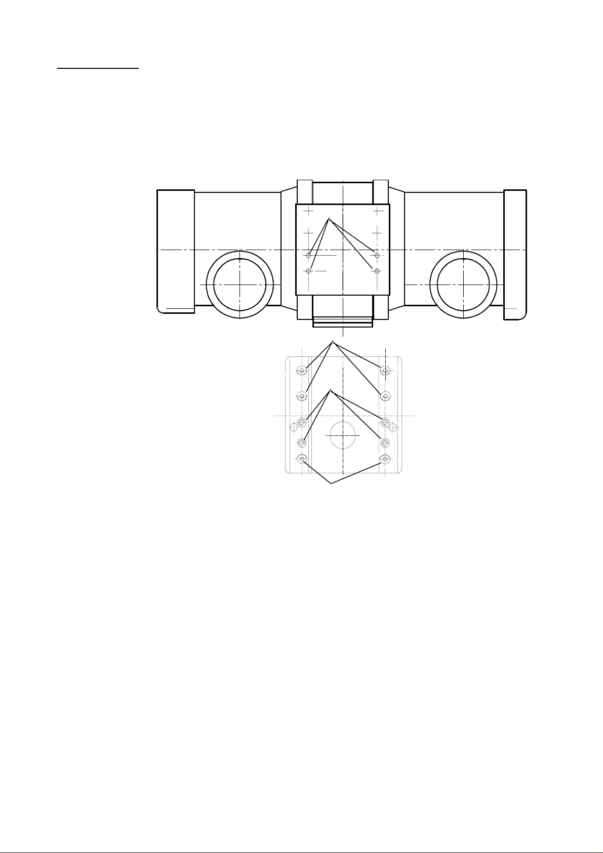
Cause :
The tube assembly is centered with respect to the system via the supporting bridge of
the tube housing. The required stability to keep the tube assembly in position with
respect to the central beam is provided by especially specified fixing screws (1).
See sketch below:
1
2
Complaints from the field and inspections of returned tube assemblies have revealed
that sometimes the fixing screws of the supporting bridge of the tube housing were
loose. It was also found out that unspecified lengths of screws were used in the field
which caused damage of the tube housing.
Remedy :
Check of whether the fixing screws are tight and, if necessary, retightening of the
fixing screws at least once a year. This work can be carried out during regular
maintenance or any other service action.
To fix the retaining rings of the supporting bridge of the tube housing use six
cheese-head screws
Code number screw M5 x 12: 2522 007 15036
Code number spring washer M5: 2512 767 06004
The supporting bridge of the tube housing is fixed at the system side with four screws
M6 x _ _
Observe the inserted screw length (7.3 mm).
1
2
(2) with hexagon socket and conical spring washers.
(1) and spring washers. The length of the screws depends on the system.
2/4 FCO74000002
ALL RIGHTS RESERVED
Copyright © 2003 Philips Medical Sy stems
Page 3

MANPOWER / TIME TO COMPLETE:
1 service engineer, 0.5 hour
TOOLS & TEST EQUIPMENT:
Standard set of service tools
DOCUMENTATION:
• Log this action in the section "History Record" of the System Reference Manual.
• File this FCO in the section "Service Information" of the System Reference Manual.
• Fill out the attached Action Notification Report and send it to your SSD Customer Services Manager.
FCO74000002 3/4
ALL RIGHTS RESERVED
Copyright © 2003 Philips Medical Sy stems
Page 4

FCO ACTION NOTIFICATION REPORT
For local SSD use only; do not return to PMG.
TITLE : Loose fixing screws on the supporting bridge of the tube housing of the tube assembly
CLASSIFICATION : service recommendation FCO REF. NO.: FCO74000002
APPLIES TO : Tube assembly combinations RO / SRO and SRM tubes with tube housings
ROT 350, ROT 351, ROT 500, ROT 501, ROT-GS 501, ROT 504, ROT-GS 505, ROT 507
HOSPITAL / ADDRESS :
LOCATION / FW SITE NO.: SALES ORDER NO. / OA NO.:
PRODUCT NUMBER :
UNIT SERIAL NUMBER :
ACTION ON THIS UNIT WAS: (select one)
JOB NO. / SERVICE INCIDENT NO.:
Completed per instruction on
Completed by the factory prior to delivery.
DATE
Not completed as this unit is not affected per instruction because: (state reason)
Not completed because customer has unit in storage.
Required parts & instructions received by the customer.
CUSTOMER ACKNOWLEDGEMENT (Required for MANDATO R Y AC TIO N S only).
The REASON and PURPOSE of this modification have been explained to me.
CUSTOMER NAME (PLEASE PRINT)
CUSTOMER SIGNATURE
TITLE
DATE
BRANCH
REGION /
SIGNATURE CUSTOMER SERVICES ENGINEER
SIGNATURE CUSTOMER SERVICES MANAGER
SERVICE UNIT /
DATE
MAIL TO : SSD Customer Services Manager
4/4 FCO74000002
4
ALL RIGHTS RESERVED
Copyright © 2003 Philips Medical Sy stems
 Loading...