


INTEGRATED CIRCUITS
DATA SH EET
PCF8575C
Remote 16-bit I/O expander for
2
I
C-bus
Product specification
File under Integrated Circuits, IC12
1999 Aug 05

Philips Semiconductors Product specification
Remote 16-bit I/O expander for I2C-bus
CONTENTS
1 FEATURES
2 GENERAL DESCRIPTION
3 ORDERING INFORMATION
4 BLOCK DIAGRAM
5 PINNING
6 FUNCTIONAL DESCRIPTION
6.1 Quasi-bidirectional I/Os
6.2 Addressing
6.3 Reading from a port (input mode)
6.4 Writing to the port (output mode)
6.5 Interrupt
7 CHARACTERISTICS OF THE I2C-BUS
7.1 Bit transfer
7.2 START and STOP conditions
7.3 System configuration
7.4 Acknowledge
8 LIMITING VALUES
9 HANDLING
10 CHARACTERISTICS
11 I2C-BUS TIMING CHARACTERISTICS
12 DEVICE PROTECTION
13 PACKAGE OUTLINE
14 SOLDERING
14.1 Introduction to soldering surface mount
packages
14.2 Reflow soldering
14.3 Wave soldering
14.4 Manual soldering
14.5 Suitability of surface mount IC packages for
wave and reflow soldering methods
15 DEFINITIONS
16 LIFE SUPPORT APPLICATIONS
17 PURCHASE OF PHILIPS I2C COMPONENTS
PCF8575C
1999 Aug 05 2

Philips Semiconductors Product specification
Remote 16-bit I/O expander for I2C-bus
1 FEATURES
• Operating supply voltage from 4.5 to 5.5 V
• Low standby current consumption of 10 µA maximum
• I2C-bus to parallel port expander
• 400 kbits/s FAST I2C-bus
• Open-drain interrupt output
• 16-bit remote I/O port for the I2C-bus
• Compatible with most microcontrollers
• Latched outputs with high current drive capability for
directly driving LEDs
• Address by 3 hardware address pins for use of up to
8 devices
• SSOP24 package.
2 GENERAL DESCRIPTION
The device is a silicon CMOS circuit. It provides general
purpose remote I/O expansion for most microcontroller
families via the two-line bidirectional bus (I2C-bus).
PCF8575C
The deviceconsists of a 16-bit quasi-bidirectional port and
an I2C-bus interface. The PCF8575C has a low current
consumption and includes latched outputs with high
current drive capability for directly driving LEDs. It also
possesses an interruptline (INT) which can beconnected
to the interrupt logic of the microcontroller. By sending an
interrupt signal on this line, the remote I/O can inform the
microcontrollerif thereis incoming dataon itsportswithout
having to communicate via the I2C-bus. This means that
the device is an I2C-bus slave transmitter/receiver.
Every data transmission fromthe PCF8575Cmust consist
of an even number of bytes, the first byte will be referred
to as P07 to P00 and the second byteas P17 to P10. The
third will be referred to as P07 to P00 and so on.
3 ORDERING INFORMATION
TYPE
NUMBER
PCF8575CTS SSOP24 plastic shrink small outline package; 24 leads; body width 5.3 mm SOT340-1
NAME DESCRIPTION VERSION
PACKAGE
1999 Aug 05 3

Philips Semiconductors Product specification
Remote 16-bit I/O expander for I2C-bus
4 BLOCK DIAGRAM
handbook, full pagewidth
INT
A0
A1
A2
SCL
SDA
1
21
2
3
22
23
INPUT
FILTER
INTERRUPT
LOGIC
PCF8575C
I2C-BUS
CONTROL
SHIFT
REGISTER
LP FILTER
16 BITS
I/O
PORT
PCF8575C
P00 to P07
4 to 11
P10 to P17
13 to 20
WRITE pulse
DD
SS
24
12
POWER-ON
RESET
V
V
READ pulse
MGS630
Fig.1 Block diagram.
1999 Aug 05 4
Philips Semiconductors Product specification
Remote 16-bit I/O expander for I2C-bus
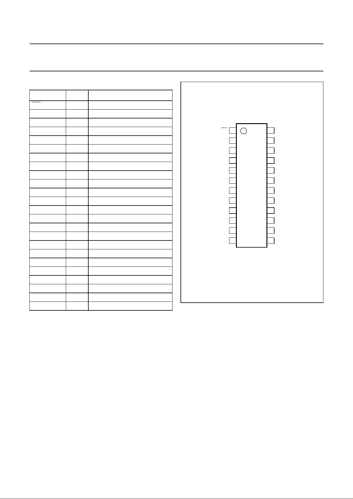
5 PINNING
SYMBOL PIN DESCRIPTION
INT 1 interrupt output (active LOW)
A1 2 address input 1
A2 3 address input 2
P00 4 quasi-bidirectional I/O 00
P01 5 quasi-bidirectional I/O 01
P02 6 quasi-bidirectional I/O 02
P03 7 quasi-bidirectional I/O 03
P04 8 quasi-bidirectional I/O 04
P05 9 quasi-bidirectional I/O 05
P06 10 quasi-bidirectional I/O 06
P07 11 quasi-bidirectional I/O 07
V
SS
P10 13 quasi-bidirectional I/O 10
P11 14 quasi-bidirectional I/O 11
P12 15 quasi-bidirectional I/O 12
P13 16 quasi-bidirectional I/O 13
P14 17 quasi-bidirectional I/O 14
P15 18 quasi-bidirectional I/O 15
P16 19 quasi-bidirectional I/O 16
P17 20 quasi-bidirectional I/O 17
A0 21 address input 0
SCL 22 serial clock line input
SDA 23 serial data line input/output
V
DD
12 supply ground
24 supply voltage
handbook, halfpage
INT
A1
A2
P00
P01
P02
1
2
3
4
5
6
24
23
22
21
20
19
PCF8575C
P03
P04
P05
P06
P07
V
SS
7
8
9
10
11
12
18
17
16
15
14
13
MGS631
Fig.2 Pin configuration.
PCF8575C
V
DD
SDA
SCL
A0
P17
P16
P15
P14
P13
P12
P11
P10
1999 Aug 05 5

Philips Semiconductors Product specification
Remote 16-bit I/O expander for I2C-bus
PCF8575C
6 FUNCTIONAL DESCRIPTION
6.1 Quasi-bidirectional I/Os
The16 ports (seeFig.3) areentirely independent andcan beused eitheras input oroutput ports.Input dataistransferred
from the ports to the microcontroller in the READ mode (see Fig.6). Output data istransmitted to the portsin the WRITE
mode (see Fig.5).
This quasi-bidirectional I/O can be used as an input or output without the use of a control signal for data direction.
At power-on all the I/Os are in 3-state mode. The strong pull-up to VDD (I
) allows a fast rising edge into a heavily
OHt
loaded output. This strong pull-up turns on when the output is written HIGH, and is switched off by the negative edge of
SCL. Afterthis short periodthe output isin 3-state mode.The I/O should bewritten HIGH beforebeing used asan input.
After power-on as all the I/Os are set to 3-state all of them can be used as inputs. Any change in setting of the I/Os as
either inputs or outputs can be donewith the write mode.Warning: If a HIGH is applied to an I/O whichhas been written
earlier to LOW, a large current (IOL) will flow to VSS (see Chapter 10; note 3).
handbook, full pagewidth
write pulse
data from
shift register
power-on
reset
DQ
FF
C
I
S
I
OHt
I
OL
V
DD
P00 to P07
P10 to 17
V
SS
Q
D
FF
C
read pulse
data to
shift register
I
S
to interrupt
MGS632
logic
Fig.3 Simplified schematic diagram of each I/O.
6.2 Addressing
Figures 4, 5 and 6 show the address and timing diagrams. Before any data is transmitted or received the master must
sendthe addressof thereceivervia theSDA line.Thefirst bytetransmitted aftertheSTART conditioncarries theaddress
of theslave deviceand theread/write bit. Theaddress ofthe slavedevice must notbe changedbetween theSTART and
the STOP conditions. The PCF8575C acts as a slave receiver or a slave transmitter.
handbook, halfpage
S 0 1 0 0 A2 A1 A0 R/W A
slave address
MGL541
Fig.4 Byte containing the slave address and the R/W bits.
1999 Aug 05 6

This text is here in white to force landscape pages to be rotated correctly when browsing through the pdf in the Acrobat reader.This text is here in
n
_white to force landscape pages to be rotated correctly when browsing through the pdf in the Acrobat reader.This text is here inThis text is here in
white to force landscape pages to berotated correctly when browsingthrough the pdf inthe Acrobat reader. white to force landscape pages tobe ...
1999 Aug 05 7
SCL
12345678
dbook, full pagewidth
Integral multiples of two bytes
Philips Semiconductors Product specification
Remote 16-bit I/O expander for I
WRITE TO
PORT
DATA OUTPUT
FROM PORT
05 OUTPUT
VOLTAGE
05 PULL-UP
OUTPUT CURRENT
INT
slave address (PCF8575C)
S 0 1 0 0 A2 A1 A0 0 A P07 P06 P00 P17 P101
start condition R/W P05acknowledge
from slave
data to port 0 data to port 1
A ASDA
acknowledge
from slave
I
OHt
t
pv
t
ir
acknowledge
from slave
Data A0 and
B0 valid
MGS633
2
C-bus
PCF8575C
Fig.5 WRITE mode (output).

This text is here in white to force landscape pages to be rotated correctly when browsing through the pdf in the Acrobat reader.This text is here in
b
_white to force landscape pages to be rotated correctly when browsing through the pdf in the Acrobat reader.This text is here inThis text is here in
white to force landscape pages to berotated correctly when browsingthrough the pdf inthe Acrobat reader. white to force landscape pages tobe ...
1999 Aug 05 8
SCL
SDA
S 0 1 0 0 A2 A1 A0 1 A P07 P06 P05 P04
P03 P02 P01 P00 P17 P10
A A P07 P00 A P17 P10 1P
ook, full pagewidth
Philips Semiconductors Product specification
Remote 16-bit I/O expander for I
READ FROM PORT
DATA INTO PORT
INT
t
iv
R/W acknowledge
from slave
t
h
t
ir
t
su
acknowledge
from receiver
t
ir
acknowledge
from receiver
P07 to P00 P17 to P10P07 to P00 P17 to P10 P07 to P00 P17 to P10
acknowledge
from receiver
MGL543
non acknowledge
from receiver
A LOW-to-HIGH transition of SDA, while SCL isHIGHisdefinedasthe STOP condition (P).Transferofdatacanbe stopped at any moment by a STOPcondition.Whenthisoccurs, data present
at the latest acknowledge phase is valid (output mode). Input data is lost.
Fig.6 READ mode (input).
2
C-bus
PCF8575C
 Loading...