

Philips pcd3332 DATASHEETS
INTEGRATED CIRCUITS
DATA SH EET
PCD3332-2; PCD3332-3;
PCD3332-S
Multistandard pulse/tone repertory
diallers/ringers
Product specification
File under Integrated Circuits, IC03
1997 Jan 13

Philips Semiconductors Product specification
Multistandard pulse/tone repertory
diallers/ringers
CONTENTS
1 FEATURES
2 GENERAL DESCRIPTION
3 ORDERING INFORMATION
4 PINNING
4.1 PCD3332-2
4.2 PCD3332-3
4.3 PCD3332-S
5 FUNCTIONAL DESCRIPTION
5.1 Pin description
5.1.1 Supply terminals (VDD and VSS)
5.1.2 Oscillator input/output (XTAL1 and XTAL2)
5.1.3 Chip enable and frequency discriminator input
(CE/FDI)
5.1.4 Cradle switch input (CSI)
5.1.5 Reset input (RESET)
5.1.6 Pulse dial and flash output (DP/FL)
5.1.7 Mute output (MUTE)
5.1.8 DTMF output (TONE)
5.1.9 Register recall (EARTH)
5.1.10 Ringer Tone Enable (RTE: PCD3332-2/S)
5.1.11 Hands-Free/Ringer Tone Enable
(HF/RTE: PCD3332-3)
5.1.12 Volume control outputs (VOL1 and VOL2)
5.1.13 Ringer volume settings
5.1.14 Dial Mode Output /Key-Tone Enable
(DMO/KTE)
5.1.15 Keyboard inputs/outputs
5.2 Keyboards
5.2.1 Keyboard function keys
5.2.2 Diode options
5.2.3 Hook modes
6 OPERATING PROCEDURES
6.1 Operating modes
6.1.1 On-hook mode or ringer mode
6.1.2 Dial mode
6.1.3 Reset delay time
6.1.4 Programming mode
6.1.5 Ringer mode (PCD3332-2)
6.1.6 Ringer mode (PCD3332-3/S)
7 LIMITING VALUES
8 CHARACTERISTICS
9 PACKAGE OUTLINES
10 SOLDERING
10.1 Introduction
10.2 DIP
10.2.1 Soldering by dipping or by wave
10.2.2 Repairing soldered joints
PCD3332-2; PCD3332-3;
PCD3332-S
10.3 SO
10.3.1 Reflow soldering
10.3.2 Wave soldering
10.3.3 Repairing soldered joints
11 DEFINITIONS
12 LIFE SUPPORT APPLICATIONS
1997 Jan 13 2
Philips Semiconductors Product specification
Multistandard pulse/tone repertory
diallers/ringers
1 FEATURES
• Pulse, DTMF and VT ‘mixed mode’ dialling
• 13 number repertory dial, up to 32 digits per number
– 10 one-touch redial or 3 one-touch plus 10 two-touch
– 250 digits maximum storage
• Last number redial up to 32 digits
• Repertory and redial memory integrity check (memory
contents check)
• Notepad memory function
• Flash and Earth register recall
• Access pause generation and termination
• On-chip power-on reset
• Supports function keys as follows:
– STORE: Program/Store
– MRC: Memory Recall
– FLASH: calibrated line-break pulse
– LNR: Last Number Redial
– PAUSE: insert access pause between stored digits
– TONE: change from pulse to DTMF dialling (mixed
mode)
– VOL+/−: speaker/ringer volume control
– 10 dedicated memory keys
• Strap functions (diode options):
– MLA: Memory Location Access selection
– RDS: Enable/Disable ringer validation delay
(PCD3332-2)
– DOO: enable/disable transmission ∗ or #
(PCD3332-3/S)
PCD3332-2; PCD3332-3;
PCD3332-S
– F/E: register recall Flash or Earth
– M/S: Mark-to-Space ratio selection (3:2or2:1)
– APT: Access Pause Timing selection
– TBT: Tone Burst Time selection
– FTS: Flash Time Selection
– P/T: Pulse or Tone (DTMF) mode selection
– RMS: Ringer Melody Selection (PCD3332-2 and
PCD3332-S)
– RFS: Ringer input frequency range selection
(19.5 to 57 Hz or 14.4 to 68 Hz) (PCD3332-3)
• Ringer tone generator
• Ringer-input frequency discriminator
• Ringer melody selection via keypad
• Volume control for loudspeaker phones (PCD3332-3)
• On-hook dialling/hands-free mode control (PCD3332-3)
• Pacifier tones.
2 GENERAL DESCRIPTION
The PCD3332-2, PCD3332-3 and PCD3332-S are
mixed-mode multistandard repertory dialler/ringer ICs,
fabricated in a low threshold voltage CMOS technology.
Dial parameters of these ICs can be set by diode options
to meet the specific requirements for various countries.
The on-chip tone generators are used for DTMF dialling
and ringer melody generation. A discriminator input
enables the tone output only if a correct ringer frequency
is applied. Repertory numbers of up to 32 digits can be
stored, with maximum storage of 250 digits.
3 ORDERING INFORMATION
TYPE
NUMBER
PCD3332-2P DIP28 plastic dual in-line package; 28 leads (600 mil) SOT117-1
PCD3332-2T SO28 plastic small outline package; 28 leads; body width 7.5 mm SOT136-1
PCD3332-3P DIP28 plastic dual in-line package; 28 leads (600 mil) SOT117-1
PCD3332-3T SO28 plastic small outline package; 28 leads; body width 7.5 mm SOT136-1
PCD3332-SP DIP28 plastic dual in-line package; 28 leads (600 mil) SOT117-1
PCD3332-ST SO28 plastic small outline package; 28 leads; body width 7.5 mm SOT136-1
1997 Jan 13 3
NAME DESCRIPTION VERSION
PACKAGE
Philips Semiconductors Product specification
Multistandard pulse/tone repertory
diallers/ringers
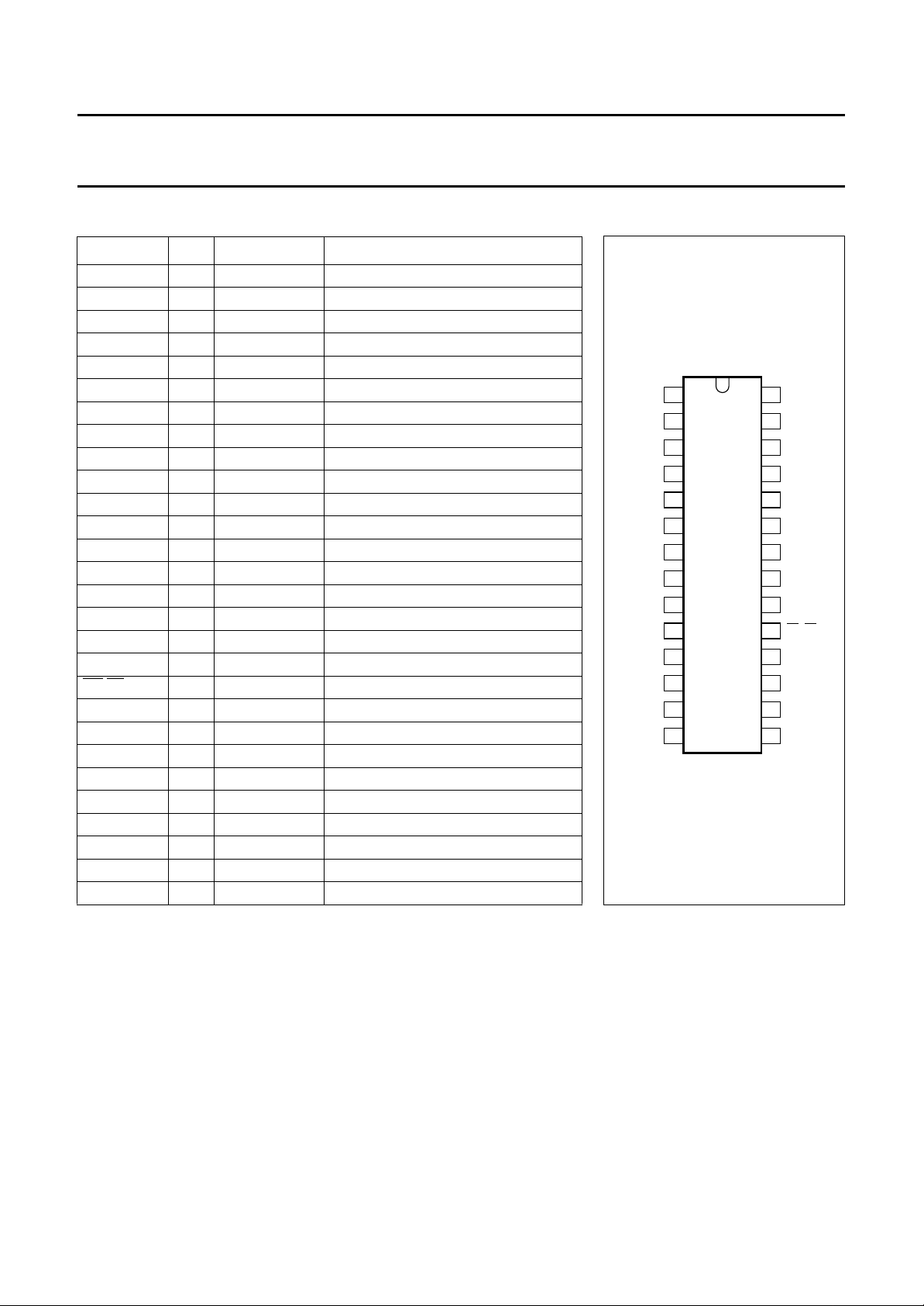
4 PINNING
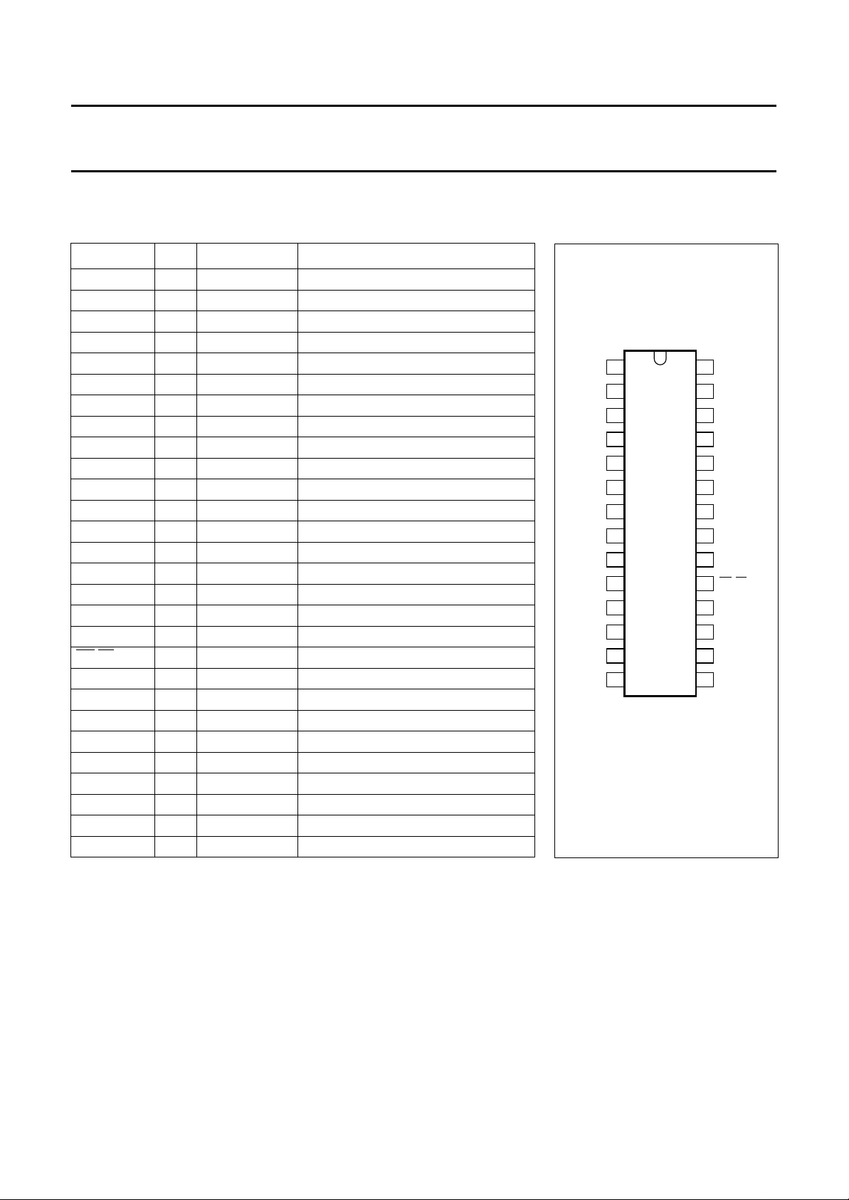
4.1 PCD3332-2
SYMBOL PIN TYPE DESCRIPTION
(2)
(4)
(4)
(2)
(4)
(3)
(3)
(4)
(4)
(1)
(1)
(1)
(1)
(1)
(1)
(1)
(1)
(1)
(1)
(1)
row 2 keyboard output
row 3 keyboard output
row 4 keyboard output
row 5 keyboard output
diode option
mute output
earth recall
column 6 input
column 5 input
column 4 input
column 3 input
column 2 input
column 1 input
dial pulse/flash output
not used, leave pin unconnected
volume 2 output
volume 1 output
dial mode output
key/ringer tone enable
row 1 keyboard output
ROW2 1 I/O
ROW3 2 I/O
ROW4 3 I/O
ROW5 4 O
DIODE 5 I/O
MUTE 6 O
EARTH 7 O
CSI 8 I cradle switch input
XTAL1 9 I oscillator input
XTAL2 10 O oscillator output
RESET 11 I reset input
CE/FDI 12 I chip enable/frequency discriminator
COL6 13 I/O
COL5 14 I/O
COL4 15 I/O
COL3 16 I/O
COL2 17 I/O
COL1 18 I/O
DP/FL 19 O
not used 20 O
VOL2 21 O
V
SS
22 P ground
TONE 23 O tone generator output
V
DD
24 P positive supply voltage
VOL1 25 O
DMO/KTE 26 O
RTE 27 O
ROW1 28 I/O
PCD3332-2; PCD3332-3;
PCD3332-S
ge
EARTH
RESET
CE/FDI
1
ROW2
2
ROW3
3
ROW4
4
ROW5
DIODE
5
6
MUTE
7
PCD3332-2
8
CSI
9
XTAL1
10
XTAL2
11
12
13
COL6
14
COL5
MBE757
Fig.1 Pin configuration.
28
27
26
25
24
23
22
21
20
19
18
17
16
15
ROW1
RTE
DMO/KTE
VOL1
V
DD
TONE
V
SS
VOL2
not used
DP/FL
COL1
COL2
COL3
COL4
Notes on types and initial states of inputs and outputs
1. Standard input or output, set to HIGH state.
2. Open-drain output, set to HIGH state.
3. Open-drain output, reset to LOW state.
4. Push-pull output, reset to LOW state.
1997 Jan 13 4
Philips Semiconductors Product specification
Multistandard pulse/tone repertory
diallers/ringers
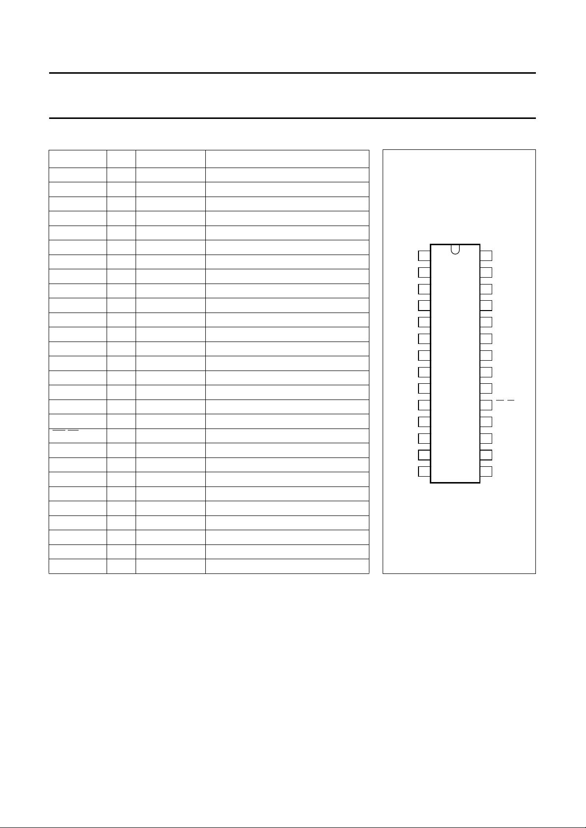
4.2 PCD3332-3
SYMBOL PIN TYPE DESCRIPTION
ROW2 1 I/O
ROW3 2 I/O
ROW4 3 I/O
ROW5 4 O
DIODE 5 I/O
MUTE 6 O
EARTH 7 O
(1)
(1)
(1)
(2)
(1)
(4)
(4)
CSI 8 I cradle switch input
XTAL1 9 I oscillator input
XTAL2 10 O oscillator output
RESET 11 I reset input
CE/FDI 12 I chip enable/frequency discriminator
COL6 13 I/O
COL5 14 I/O
COL4 15 I/O
COL3 16 I/O
COL2 17 I/O
COL1 18 I/O
DP/FL 19 O
LFE 20 O
VOL2 21 O
V
SS
22 P ground
(1)
(1)
(1)
(1)
(1)
(1)
(2)
(4)
(3)
TONE 23 O tone generator output
V
DD
VOL1 25 O
DMO/KTE 26 O
HF/RTE 27 O
ROW1 28 I/O
24 P positive supply voltage
(3)
(4)
(4)
(1)
row 2 keyboard output
row 3 keyboard output
row 4 keyboard output
row 5 keyboard output
diode option
mute output
earth recall
column 6 input
column 5 input
column 4 input
column 3 input
column 2 input
column 1 input
dial pulse/flash output
low-frequency amplifier enable
volume 2 output
volume 1 output
dial mode output
hands-free/ringer tone enable
row 1 keyboard output
PCD3332-2; PCD3332-3;
PCD3332-S
ge
DIODE
EARTH
RESET
CE/FDI
1
ROW2
2
ROW3
3
ROW4
4
ROW5
5
6
MUTE
7
PCD3332-3
8
CSI
9
XTAL1
10
XTAL2
11
12
13
COL6
14
COL5
MBE752
Fig.2 Pin configuration.
28
27
26
25
24
23
22
21
20
19
18
17
16
15
ROW1
HF/RTE
DMO/KTE
VOL1
V
DD
TONE
V
SS
VOL2
LFE
DP/FL
COL1
COL2
COL3
COL4
Notes on types and initial states of inputs and outputs
1. Standard input or output, set to HIGH state.
2. Open-drain output, set to HIGH state.
3. Open-drain output, reset to LOW state.
4. Push-pull output, reset to LOW state.
1997 Jan 13 5
Philips Semiconductors Product specification
Multistandard pulse/tone repertory
diallers/ringers
4.3 PCD3332-S
SYMBOL PIN TYPE DESCRIPTION
ROW2 1 I/O
ROW3 2 I/O
ROW4 3 I/O
ROW5 4 O
DIODE 5 I/O
MUTE 6 O
EARTH 7 O
(1)
(1)
(1)
(2)
(1)
(4)
(4)
CSI 8 I cradle switch input
XTAL1 9 I oscillator input
XTAL2 10 O oscillator output
RESET 11 I reset input
CE/FDI 12 I chip enable/frequency discriminator
COL6 13 I/O
COL5 14 I/O
COL4 15 I/O
COL3 16 I/O
COL2 17 I/O
COL1 18 I/O
DP/FL 19 O
not used 20 O
VOL2 21 O
V
SS
22 P ground
(1)
(1)
(1)
(1)
(1)
(1)
(2)
(4)
(3)
TONE 23 O tone generator output
V
DD
VOL1 25 O
DMO/KTE 26 O
RTE 27 O
ROW1 28 I/O
24 P positive supply voltage
(3)
(4)
(4)
(1)
row 2 keyboard output
row 3 keyboard output
row 4 keyboard output
row 5 keyboard output
diode option
mute output
earth recall
column 6 input
column 5 input
column 4 input
column 3 input
column 2 input
column 1 input
dial pulse/flash output
not used, leave pin unconnected
volume 2 output
volume 1 output
dial mode output
key/ringer tone enable
row 1 keyboard output
PCD3332-2; PCD3332-3;
PCD3332-S
age
EARTH
RESET
CE/FDI
1
ROW2
2
ROW3
3
ROW4
4
ROW5
DIODE
5
6
MUTE
7
PCD3332-S
8
CSI
9
XTAL1
10
XTAL2
11
12
13
COL6
14
COL5
MBE754
Fig.3 Pin configuration.
28
27
26
25
24
23
22
21
20
19
18
17
16
15
ROW1
RTE
DMO/KTE
VOL1
V
DD
TONE
V
SS
VOL2
not used
DP/FL
COL1
COL2
COL3
COL4
Notes on types and initial states of inputs and outputs
1. Standard input or output, set to HIGH state.
2. Open-drain output, set to HIGH state.
3. Open-drain output, reset to LOW state.
4. Push-pull output, reset to LOW state.
1997 Jan 13 6
Philips Semiconductors Product specification
Multistandard pulse/tone repertory
diallers/ringers
5 FUNCTIONAL DESCRIPTION
References to the ‘PCD3332’ or the ‘device’ apply to the
PCD3332-2, the PCD3332-3 and the PCD3332-S.
5.1 Pin description
5.1.1 S
To retain data in the RAM, the standby supply voltage of
1 V, must be maintained. To ensure that the contents of
the RAM are secure in the event of a power failure, a
capacitor may be connected across the supply terminals.
The capacitor must have a suitable value to maintain the
standby voltage for a certain period of time. The minimum
operating voltage of these devices is 2.5 V. The internal
power-on reset is enabled for a voltage below this
minimum operating voltage.
5.1.2 O
The time base for the PCD3332 is a crystal-controlled
on-chip oscillator, which incorporates a 3.58 MHz crystal
or ceramic resonator connected between XTAL1 and
XTAL2. It should be noted that when using a ceramic
resonator, the minimum supply voltage increases.
The oscillator starts when VDD reaches its operating
voltage level and CE = HIGH (min. 2.5 V).
5.1.3 C
For DC inputs this pin acts as the chip enable (CE) input,
and is active HIGH. CE in combination with the Cradle
Switch Input (CSI) determines the mode of the device.
See Table 1.
For AC inputs the pin acts as the (ringer) Frequency
Discriminator Input (FDI).
To generate a correct ringer output tone, the input
frequency must be between 19.5 Hz and 57 Hz;
frequencies below 18 Hz and higher than 64 Hz are
omitted.
The PCD3332-3 has a second (diode selectable) range of
valid input frequencies of 14.5 Hz to 68 Hz; frequencies
below 14 Hz and higher than 76 Hz are omitted.
Ringer response timing and detection is illustrated in
Fig.15.
UPPLY TERMINALS (VDDAND V
SCILLATOR INPUT/OUTPUT (XTAL1 AND XTAL2)
HIP ENABLE AND FREQUENCY DISCRIMINATOR
(CE/FDI)
INPUT
SS
)
PCD3332-2; PCD3332-3;
PCD3332-S
5.1.4 C
CSI is normally generated from the physical ‘off-hooking’
of the phone. CSI in combination with CE/FDI determines
the operating mode of the PCD3332, as shown in Table 1.
Table 1 Different modes of the PCD3332
INPUT CSI INPUT CE/FDI PCD3332 STATUS
5.1.5 R
RESET activates the on-chip reset circuit and is active
HIGH. The reset circuit initializes all inputs and outputs.
Two other events will cause the chip to initialize:
• CE going HIGH
• VDD falling below 2.5 V, then being restored (power-on
reset).
For this reason, RESET may not be required, and can be
connected to VSS. This should preferably be via a 100 kΩ
resistor, to save leakage current.
Note that a suitable capacitor connected between VDD and
VSS will inhibit the decrease of voltage at VDD after a power
failure, and thus extend the time until the power-on reset is
initiated.
5.1.6 P
This pin is the output for:
• The dial pulse sequence (DP)
• The calibrated LOW pulse (FL) after the FLASH key is
pressed.
The dialling sequence for pulse dialling is shown in Figs 11
and 12. DP/FL starts HIGH, pulses are LOW, and the
inter-digit pauses are HIGH. Thus, DP/FL is HIGH during
a line-make and LOW during a line-break.
If the Flash/Earth diode option is set to FLASH, then when
FLASH is pressed a LOW pulse is output, with a calibrated
duration also determined by diode option.
RADLE SWITCH INPUT (CSI)
LOW LOW stop or power-down
mode
HIGH LOW idle mode
LOW HIGH ringer mode
HIGH HIGH conversation or
off-hook mode
ESET INPUT (RESET)
ULSE DIAL AND FLASH OUTPUT (DP/FL)
1997 Jan 13 7
Philips Semiconductors Product specification
Multistandard pulse/tone repertory
diallers/ringers
5.1.7 MUTE OUTPUT (MUTE)
During the dialling sequence this push-pull output is
activated. In the pulse dialling mode, MUTE goes HIGH
prior to the dialling action and goes LOW after the last
t
(interdigit pause), see Figs 11 and 12. In DTMF
idp
dialling, MUTE goes HIGH prior to the dialling action and
goes LOW after an additional ‘holdover’ time, see
Figs 13 and 14.
This output is also activated if the device enters the
programming mode, to avoid transmitting the keys
entered.
5.1.8 DTMF
The timing sequence for DTMF dialling is illustrated in
Figs 13 and 14. The tones generated by this TONE are
filtered by an on-chip switched capacitor filter, and active
Table 2 DTMF frequency tolerances
ROW/COL
ROW 1 697 697.90 +0.13 +0.90
ROW 2 770 770.46 +0.06 +0.46
ROW 3 852 852.45 −0.18 −1.55
ROW 4 941 943.23 +0.24 +2.23
COL 1 1209 1206.45 −0.21 −2.55
COL 2 1336 1341.66 +0.42 +5.66
COL 3 1477 1482.21 +0.35 +5.21
OUTPUT (TONE)
STANDARD
FREQUENCY (Hz)
FREQUENCY (Hz)
RC low-pass filter. Therefore, the total harmonic distortion
fulfils the CEPT CS203 recommendations. An on-chip
reference voltage provides output tone levels independent
of supply voltages and temperatures. Spread among the
individual parts is extremely low.
The DC level of the TONE output measures 0.5V
the impedance is 100 Ω (typ.). Table 2 shows the
frequency tolerances.
The TONE output is also used to generate the ringer
melody, key entry acceptance beep, error or warning
beeps and confirmation beeps. These beeps are
generated/set in programming mode as a response to the
users action. The ringer is designed to generate
3-melodies that may be selected using the keyboard.
Table 3 shows the implemented ringer melodies.
OUTPUT
PCD3332-2; PCD3332-3;
PCD3332-S
DEVIATION
(%)
DEVIATION
(Hz)
DD
and
Table 3 Ringer melodies
KEY DEPRESSED TONE 1 (Hz) TONE 2 (Hz) TONE 3 (Hz) TONE ON TIME (ms)
1 826 925 1037 30
2 1037 1161 1297 30
3 1297 1455 1621 30
Table 4 Beep frequencies
BEEP FUNCTION TONE 1 (Hz) TONE 2 (Hz) TONE 3 (Hz) TONE ON TIME (ms)
Key accept 2358 −− 40 −
Error 2358 2358 2358 134 35
Confirmation 806 899 1010 134 67
1997 Jan 13 8
TONE OFF TIME
(ms)

Philips Semiconductors Product specification
Multistandard pulse/tone repertory
diallers/ringers
5.1.9 REGISTER RECALL (EARTH)
If the Flash/Earth diode option of the PCD3332 is set to the
Earth, then dialling the EARTH either out of
Repertory/LNR or by pressing the FLASH key will
generate a HIGH pulse at the push-pull output EARTH for
a calibrated time. Figures 12 and 14 illustrate the EARTH
timing relationship with other signals. The calibrated
EARTH time is followed by an interdigit time t
dialling of EARTH can only be performed after the interdigit
time has elapsed.
If the Flash key was the first key depressed directly after
going off-hook, followed by a second depressing of the
Flash key while the EARTH is still in progress, then the
second depression will be ignored.
5.1.10 R
The PCD3332-2 and PCD3332-S generate tones for the
ringer output stage and key tones when depressing a
function key at the keypad. Output RTE will go HIGH and
stay HIGH for the duration of the tone generated at output
TONE.
5.1.11 H
The PCD3332-3 generates tones for the ringer output
stage and key tones when depressing a function key at the
keypad. Output HF/RTE will go HIGH and stay HIGH for
the duration of the tone generated at output TONE.
During the conversation mode, HF/RTE is used for
enabling the hands-free mode. Depressing the HOOK key
will change the operation mode as follows:
• Change from on-hook (stop mode) to hands-free mode
• Toggles the listening-in mode
• Change from handset to hands-free.
5.1.12 V
INGER TONE ENABLE (RTE: PCD3332-2/S)
ANDS-FREE/RINGER TONE ENABLE (HF/RTE:
PCD3332-3)
OLUME CONTROL OUTPUTS (VOL1 AND VOL2)
5.1.12.1 PCD3332-2
. A second
idp
PCD3332-2; PCD3332-3;
PCD3332-S
Table 5 shows the volume outputs setting, as well as the
default setting in case of a power failure or if the power is
supplied for the first time.
5.1.12.2 PCD3332-3
The PCD3332-3 has the facility to control the ringer output
signal and the loudspeaker signal during listening-in or
hands-free operation. Depressing the keys VOL− or VOL+
during the ringer mode will change the ringer volume
setting. Depressing the keys VOL− or VOL+ during the
conversation mode will change the loudspeaker volume
setting.
If the maximum volume level is reached, depressing the
VOL+ key will not change the volume setting. If the
minimum volume level is reached, depressing the VOL−
key will not change the volume setting. Selection between
ringer volume or conversation mode volume, is performed
in the hardware using the HF/RTE output. In the ringer
mode the output HF/RTE is HIGH.
Table 5 shows the volume outputs setting, as well as the
default setting in case of a power failure or if the power is
supplied for the first time.
5.1.12.3 PCD3332-S
The PCD3332-S has the facility to control the ringer output
signal by depressing the keys VOL− or VOL+ during the
ringer mode.
If the maximum volume level is reached, depressing the
VOL+ key will not change the volume setting. If the
minimum volume level is reached, depressing the VOL−
key will not change the volume setting. Selection between
ringer volume or conversation mode volume, is performed
in the hardware using the RTE output. In the ringer mode
the output RTE is HIGH.
Table 5 shows the volume outputs setting, as well as the
default setting in case of a power failure or if the power is
supplied for the first time.
The PCD3332-2 has the facility to control the ringer output
signal, as well as the loudspeaker volume, by depressing
the keys ∗/VOL− or #/ VOL+ during the ringer mode.
If the maximum volume level is reached, depressing
#/VOL+ key will not change the volume setting. If the
minimum volume level is reached, depressing ∗/VOL− key
will not change the volume setting. Selection between
ringer volume or conversation mode volume, is performed
in the hardware using the RTE output. In the ringer mode
the output RTE is HIGH.
1997 Jan 13 9
Philips Semiconductors Product specification
Multistandard pulse/tone repertory
diallers/ringers
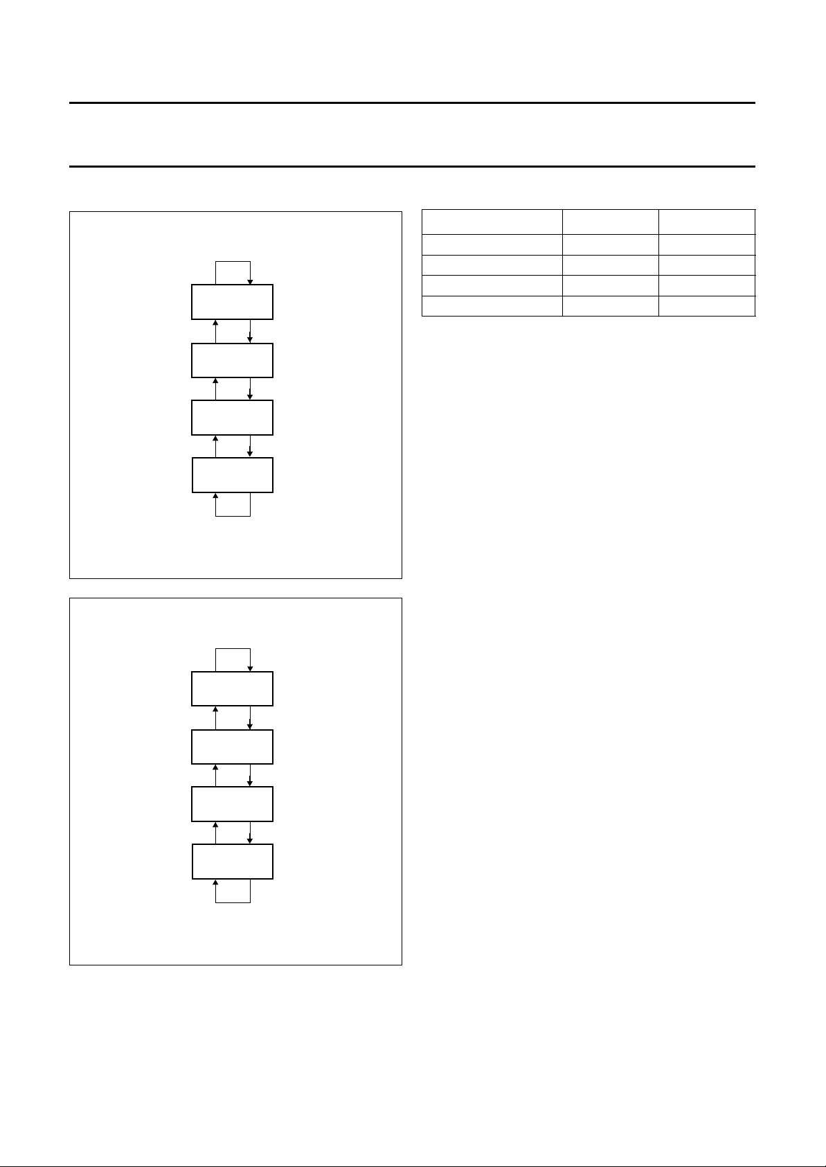
5.1.13 RINGER VOLUME SETTINGS
handbook, halfpage
Fig.4 FSM for volume control (PCD3332-2).
VOL+/#
VOL+/#
VOL+/#
VOL+/#
MGC616
DEFAULT
VOLUME
HIGH
VOLUME
LOW
VOLUME
LOWEST
VOLUME
VOL−/*
VOL−/*
VOL−/*
VOL−/
*
PCD3332-2; PCD3332-3;
PCD3332-S
Table 5 State assignment
STATE VOL2 VOL1
Default volume setting HIGH HIGH
High volume setting HIGH LOW
Low volume setting LOW HIGH
Lowest volume setting LOW LOW
5.1.14 D
In the PULSE dialling mode the DMO/KTE output is
activated (HIGH), at dialling the Make/Brake pulse dial
sequences. Figures 11 and 12 illustrate the signal timing
relationship.
In the programming mode, the DMO/KTE output is
activated at the same time the key beeps are generated at
output TONE and may be used to enable the key tone to
the earpiece amplifier.
5.1.15 K
A single contact keyboard with a maximum of 6 columns
and 5 rows can be connected to the PCD3332-2.
The keyboard scanning is started if a key depression is
detected. The rows are scanned while the columns are
used as sense inputs.
IAL MODE OUTPUT /KEY-TONE ENABLE
(DMO/KTE)
EYBOARD INPUTS/OUTPUTS
handbook, halfpage
VOL+
VOL+
VOL+
VOL+
MGC615
DEFAULT
VOLUME
HIGH
VOLUME
LOW
VOLUME
LOWEST
VOLUME
VOL−
VOL−
VOL−
VOL−
Fig.5 FSM for volume control (PCD3332-3/S).
To overcome key bouncing, a debounce on/off time of
approximately 14 to 20 ms is implemented.
Only one single key depression is validated and accepted
at any one time. Once a key is accepted the keyboard
scanning is continued until no further keys are depressed.
This means that if a key is accepted but still depressed
while a second key is entered, the second key depression
is ignored. Also, if two or more keys are depressed within
the debounce time while no key is yet accepted, all keys
are ignored.
Keyboard detection is also performed in the ringer mode to
enable the ringer volume setting and ringer melody
selection.
In the on-hook mode or power-down mode of the
PCD3332-2 and PCD3332-S, the keyboard I/Os are set to
HIGH except ROW 5 which is set to LOW.
1997 Jan 13 10
 Loading...