

Philips PCD3330-1P, PCD3330-1T Datasheet
INTEGRATED CIRCUITS
DATA SH EET
PCD3330-1
Multistandard repertory
dialler/ringer with EEPROM
Product specification
Supersedes data of September 1992
File under Integrated circuits, IC03
1997 Jan 15

Philips Semiconductors Product specification
Multistandard repertory dialler/ringer
with EEPROM
CONTENTS
1 FEATURES
1.1 Pulse/DTMF dialling
1.2 Number storage
1.3 Ringer
1.4 General
2 GENERAL DESCRIPTION
3 ORDERING INFORMATION
4 PINNING
5 FUNCTIONAL DESCRIPTION
5.1 Inputs/Outputs
5.1.1 COL1 to COL6, keyboard inputs
5.1.2 DMO, dial mode output
5.1.3 HOOK, on/off hook detection input
5.1.4 XTAL1 and XTAL2, oscillator input/output
5.1.5 RESET, reset input
5.1.6 CE/RF, chip enable and ringer-frequency
detect input
5.1.7 ROW1 to ROW6, keyboard outputs
5.1.8 MUTE, mute output
5.1.9 RTO, ringer tone output
5.1.10 DP/FL, pulse dialling and register recall output
5.1.11 VDD and V
5.1.12 TONE, DTMF or ringer tone output
5.1.13 PD/DTMF, pulse/tone mode selection
5.1.14 RVOL1 and RVOL2/LSE, ringer volume
outputs
5.1.15 EARTH, a/b line to earth connection
5.2 Keyboard
5.3 EEPROM organization and programming
procedures
5.3.1 EEPROM organization
5.3.2 EEPROM programming procedures
5.3.2.1 Factory EEPROM programming procedure
5.3.2.2 EEPROM programming procedures via
keyboard
5.4 Operation mode overview
5.5 Pulse/DTMF dialling function
5.5.1 Pulse/DTMF mode selection by pin
5.5.2 Pulse dialling (PD/DTMF = LOW)
5.5.3 Dual tone multi frequency (DTMF) dialling
(PD/DTMF = HIGH)
5.5.4 DTMF dialling in pulse dialling mode (mixed
mode dialling)
5.5.5 Flash or Earth function
5.5.6 Disconnect function
5.5.7 Mute function (M-key)
5.5.8 On-hook dialling control
5.6 Number storage, transmission and redial
5.6.1 Number storage and transmission
SS
PCD3330-1
5.6.2 Last number redial (1 to 24 digits)
5.6.3 Access pause by Cursor method
5.6.4 Access pause by Atlanta procedure
5.6.5 10-number repertory dialling
5.6.5.1 Chain dialling
5.6.6 3-number repertory dialling
5.6.7 Access pause storage
5.6.8 Manual access pauses
5.6.9 Storing repertory numbers
5.7 Ringer function
5.7.1 Ringer output pin selection
5.7.2 Ringer input frequency measurement
5.7.3 Ringer melodies selection
5.7.4 Ringer volume change during conversation and
ringer mode
5.7.5 Ringer repetition rate change during
conversation and ringer mode
6 LIMITING VALUES
7 HANDLING
8 DC CHARACTERISTICS
9 APPLICATION INFORMATION
10 PACKAGE OUTLINES
11 SOLDERING
11.1 Introduction
11.2 DIP
11.2.1 Soldering by dipping or by wave
11.2.2 Repairing soldered joints
11.3 SO
11.3.1 Reflow soldering
11.3.2 Wave soldering
11.3.3 Repairing soldered joints
12 DEFINITIONS
13 LIFE SUPPORT APPLICATIONS
1997 Jan 15 2

Philips Semiconductors Product specification
Multistandard repertory dialler/ringer with
EEPROM
1 FEATURES
1.1 Pulse/DTMF dialling
• Pulse, DTMF and ‘mixed mode’ dialling
• Mixed mode dialling: start with pulse dial, end with
DTMF dial (e.g. for control of DTMF user equipment via
a pulse network)
• Number of digits per call is infinite (FIFO register)
• Flash or register recall
• Connect a/b to earth function
• Mute functions
• Disconnect function
• Supports 16 dial key: 0 to 9 and ∗, #, A, B, C and D
• Supports up to 6 × 6 keyboard and various function keys
including:
– FLASH: calibrated line-break pulse
– HOOK: toggle on-hook/off-hook or loudspeaker
on/off
– MUTE: activate/deactivate mute output
– TONE: change to DTMF dialling (mixed mode)
– DISconnect: return to on-hook state for calibrated
time
• On-hook dialling control
• Country specifications which can be stored in EEPROM
are:
– ∗ and # to be transmitted/not transmitted when
switching over to DTMF dialling mode
– mark-to-space ratio (3:2or2:1)
– 6 tone time selections (60/90, 70/70, 80/80, 100/100,
100/140 or 140/140 ms)
– 4 flash time selections (100, 115, 270 or 600 ms)
– mute output type selection (M1,
– microphone mute generated via the LSE output
– DTMF keys or Function keys selection
• On-chip voltage reference for stabilized supply and
temperature independent tone output
• On-chip filtering for low output distortion (CEPT
compatible).
M1, M2 or M2)
PCD3330-1
1.2 Number storage
• Redial by ‘cursor’ method (maximum 24 digits) stored in
internal EEPROM
• Storage for 13 repertory dial numbers (16 digits each) or
10 repertory dial numbers (20 digits each) in internal
EEPROM
• Access pause generation and termination: manually or
by ‘Atlanta’ procedure
• Function keys for: LNR, Memory recall, Store, Access
Pause and 1 key repertory
• Country specifications which can be stored in EEPROM
are:
– access pause time selection (1.5/1.0, 2.5/1.5,
3.0/3.5 or 6.0/6.0 s)
– 10 number repertory dialler selection (1 or 2 key)
– two repertory number programming procedures
(General or Germany)
– repertory length (16 or 20 digits)
– generating a keytone during program actions.
1.3 Ringer
• Ringer input frequency detection
• Function key for: Program Ringer
• Three-tone ringer with 4 different ringer frequencies
• Ringer melody generation with four signal speeds and
four output volume steps, keypad controlled
• Country specifications which can be stored in EEPROM
are:
– ringer input frequency detection selection
– ringer output selection (via DTMF tone output or
special ringer tone output)
– 4 possible ringer melodies
– 4 possible ringer repetition rates
– 4 possible ringer volumes.
1.4 General
• On-chip oscillator uses low-cost 3.58 MHz (TV colour
burst) crystal or PXE resonator
• On-chip power-on reset (typically 2.0 V)
• Supply voltage range 1.8 to 6.0 V (2.5 to 6.0 V in
EEPROM erase/write and DTMF and ringer mode).
1997 Jan 15 3
Philips Semiconductors Product specification
Multistandard repertory dialler/ringer with
PCD3330-1
EEPROM
2 GENERAL DESCRIPTION
The PCD3330-1 is a mixed-mode multistandard repertory
dialler/ringer IC fabricated in a low threshold voltage
CMOS technology.
The (maximum 13) repertory numbers, redial and various
country specifications are stored in EEPROM so that
memory retention is guaranteed for 10 years without using
a battery back-up.
National telecommunications specifications can be fulfilled
by changing a few bytes in EEPROM which contain the
different telephone timing and dialling procedures.
The two on-chip tone generators are used for Dual Tone
Multi-Frequency (DTMF) dialling, and for generating a
melody during ringing, which is activated when a correct
incoming ringer frequency is detected.
3 ORDERING INFORMATION
TYPE
NUMBER
PCD3330-1P DIP28 plastic dual in-line package; 28 leads (600 mil) SOT117-1
PCD3330-1T SO28 plastic small outline package; 28 leads; body width 7.5 mm SOT136-1
NAME DESCRIPTION VERSION
As an output transducer for the ringer, a loudspeaker
(ringer out via tone output) or a PXE (ringer out via the
special ringer output which generates square wave ringer
tones with a peak-to-peak voltage of V
used.
The operating supply voltage is 1.8 V (2.5 V in EEPROM
erase/write and DTMF and ringer mode) to 6.0 V with a low
current consumption in all operating modes: standby,
conversation, dialling, programming and ringer.
PACKAGE
to VSS) can be
DD
1997 Jan 15 4
Philips Semiconductors Product specification
Multistandard repertory dialler/ringer with
EEPROM
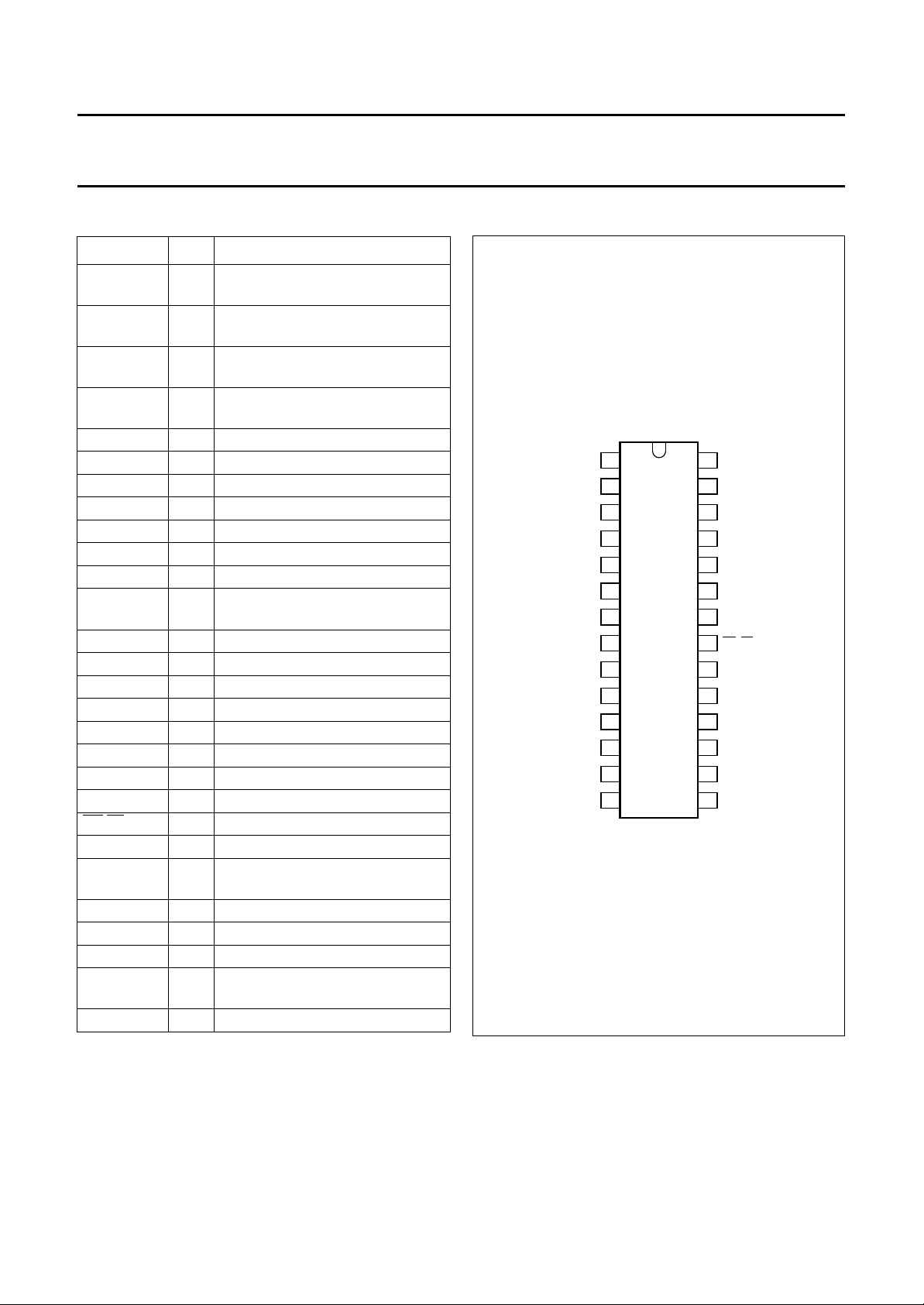
4 PINNING
SYMBOL PIN DESCRIPTION
COL1 1 sense column keyboard
input/programming EEPROM
COL2 2 sense column keyboard
input/programming EEPROM
COL3 3 sense column keyboard
input/programming EEPROM
COL4 4 sense column keyboard
input/programming EEPROM
COL5 5 sense column keyboard input
COL6 6 sense column keyboard input
DMO 7 dial mode output
HOOK 8 cradle contact input
XTAL1 9 crystal/PXE oscillator input
XTAL2 10 crystal/PXE oscillator output
RESET 11 reset input
CE/RF 12 chip enable and zero crossing for
ringer input
ROW1 13 scanning row keyboard output
ROW2 14 scanning row keyboard output
ROW3 15 scanning row keyboard output
ROW4 16 scanning row keyboard output
ROW5 17 scanning row keyboard output
ROW6 18 scanning row keyboard output
MUTE 19 mute output
RTO 20 ringer melody output
DP/FL 21 dial pulse/flash inverted output
V
SS
TONE 23 DTMF tones or ringer melody
V
DD
PD/DTMF 25 pulse/DTMF dial selection
RVOL1 26 ringer volume output 1
RVOL2/LSE 27 ringer volume output 2
EARTH 28 earth output
22 negative supply
output
24 positive supply
/loudspeaker enable output
handbook, halfpage
COL1
1
COL2
2
COL3
3
COL4
4
COL5
5
COL6
6
DMO
7
PCD3330-1
8
HOOK
XTAL1
9
XTAL2
10
RESET
11
CE/RF
12
ROW1
13
ROW2
MGG571
Fig.1 Pin configuration.
PCD3330-1
EARTH
28
RVOL2/LSE
27
RVOL1
26
PD/DTMF
25
V
24
DD
23
TONE
V
22
SS
21
DP/FL
RTO
20
MUTE
19
ROW6
18
ROW5
17
ROW4
16
1514
ROW3
1997 Jan 15 5

Philips Semiconductors Product specification
Multistandard repertory dialler/ringer with
EEPROM
5 FUNCTIONAL DESCRIPTION
5.1 Inputs/Outputs
5.1.1 COL1
The sense column inputs COL1 to COL6 and the scanning
row outputs ROW1 to ROW6 can be directly connected to
several keyboard layouts, up to a maximum 6 × 6 single
contact keyboard matrix.
Four of the sense columns are used to store the contents
of the EEPROM in the factory (see Section 5.3).
5.1.2 DMO,
This output is HIGH during the make and break times in
pulse dial mode. Its function is to lower the DC line voltage
during these pulses.
This output is LOW during DTMF dialling, during the
inter-digit-pause in pulse dial mode and during
conversation mode.
5.1.3 HOOK,
TO COL6, KEYBOARD INPUTS
DIAL MODE OUTPUT
ON/OFF HOOK DETECTION INPUT
PCD3330-1
network). When the RESET input becomes HIGH it
initializes the IC.
The RESET-pin should not be left open (not-connected) in
any circumstances.
5.1.6 CE/RF,
DETECT INPUT
As chip enable input (active HIGH) it is used to initialize
part of the system, to switch from standby to the ringer or
conversation, programming or dialling mode and to detect
line breaks.
As ringer-frequency input it measures the time between
two LOW-to-HIGH transitions, thus measuring the ringer
frequency.
5.1.7 ROW1
The scanning row outputs ROW1 to ROW6 and the sense
column inputs COL1 to COL6 can directly be connected to
several keyboard layouts (max. a 6 × 6 single contact
keyboard matrix).
CHIP ENABLE AND RINGER-FREQUENCY
TO ROW6, KEYBOARD OUTPUTS
If inputs CE and HOOK are both HIGH then the
conversation, programming or dialling mode is selected.
Switching the HOOK input LOW longer than the
reset-delay-time results in switching to the standby mode.
If CE = HIGH and HOOK = LOW the PCD3330-1 is in the
ringer mode.
5.1.4 XTAL1
AND XTAL2, OSCILLATOR INPUT/OUTPUT
Time base for the PCD3330-1 is a crystal-controlled
on-chip oscillator which is completed by connecting a
3.579545 MHz crystal or ceramic resonator (PXE)
between XTAL1 and XTAL2. The XTAL2 is the oscillator
output and can be used as driver for another oscillator
input. A low-cost quartz crystal from Philips (code number.
4322 143 04401) is available, specially for telephony
applications.
The oscillator starts when VDD reaches the operating
voltage level and CE = HIGH.
5.1.5 RESET,
RESET INPUT
When the RESET pin is connected to VSS, a reset is
generated by an internal power-on-reset circuit, which
produces an internal reset pulse every time that the supply
voltage VDD crosses the power-on-reset voltage level
(typ. 2.0 V).
Depending on the application it can be necessary to
generate a reset via an external circuit (e.g. an external RC
5.1.8 MUTE,
MUTE OUTPUT
The MUTE output is used during dialling. In the
PCD3330-1 the MUTE output has four different selectable
options:
• M1, normally LOW, but HIGH during inter-digit-pause
and make/break in pulse dial mode, during tone-on and
tone-off in DTMF mode, and during flash or earth
• M1, the inverted signal of M1
• M2, normally LOW, HIGH during make/break in pulse
dial mode, during tone-on in DTMF mode, and during
flash or earth
• M2, the inverted signal of M2.
Each time the M-key on the keyboard is pressed the MUTE
output goes to its inverted state.
5.1.9 RTO,
RINGER TONE OUTPUT
This is the special ringer output. When this output is
selected the output of the internal tone generators is not
connected to the TONE output but to this RTO output.
The ringer output signal has a peak to peak square output
voltage of VDD− VSS (this is used with a PXE transducer).
5.1.10
DP/FL, PULSE DIALLING AND REGISTER RECALL
OUTPUT
TheDP/FL output drives an external switching transistor in
pulse dial mode.
1997 Jan 15 6

Philips Semiconductors Product specification
Multistandard repertory dialler/ringer with
EEPROM
It pulses a calibrated FLASH or register recall pulse
(if selected) when the keyboard input FLASH is pressed.
5.1.11 V
VDD and VSS are the supply terminals.
5.1.12 TONE, DTMF
In DTMF dialling mode the dual tones which are provided
at the output TONE are filtered by an on-chip switched
capacitor filter, followed by an active RC low-pass filter.
Therefore, the total harmonic distortion of the DTMF tones
fulfils the CEPT recommendations. An on-chip reference
voltage provides output tone levels independent of supply
voltages. The impedance is 100 Ω typically.
In ringer mode this TONE output can be used for
generating the ringer output tones. Whether this TONE
output or the special RTO (ringer tone) output is used is
selected via EEPROM.
5.1.13 PD/DTMF,
To select the dialling mode, this input PD/DTMF must be
connected to VDD or VSS.
PD/DTMF = HIGH (VDD) = DTMF mode.
PD/DTMF = LOW (VSS) = pulse mode.
The PCD3330-1 accept the information also during
manual dialling. Switching the input to pin PD/DTMF
changes the dialling mode after finishing the digit in
progress.
DD
AND V
SS
OR RINGER TONE OUTPUT
PULSE/TONE MODE SELECTION
PCD3330-1
microphone mute which is controlled by the M-key.
After off-hook this output is HIGH and will toggle by every
press off the M-key.
5.1.15 EARTH, a/b
The EARTH output drives an external switching transistor.
which connects the a- or b-line to earth.
It pulses a calibrated EARTH pulse (if selected) when the
keyboard input FLASH is pressed.
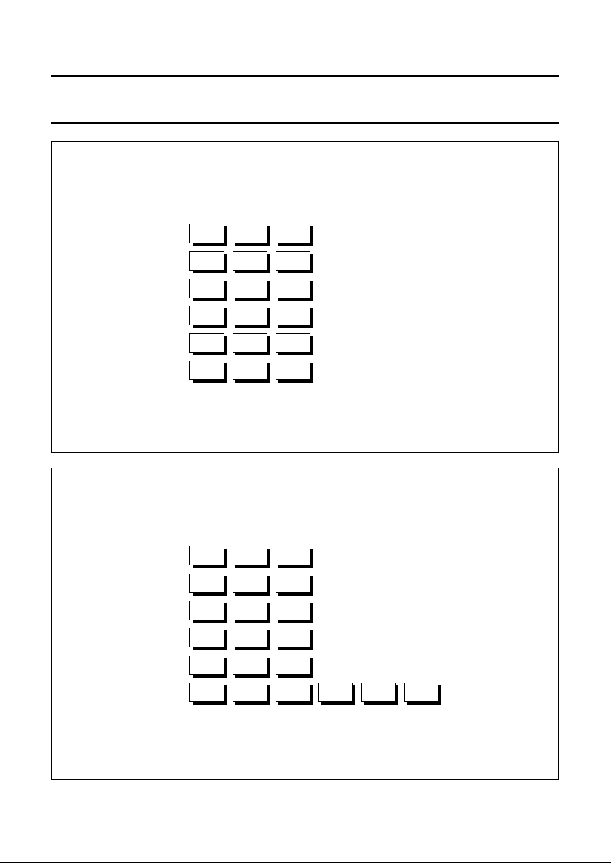
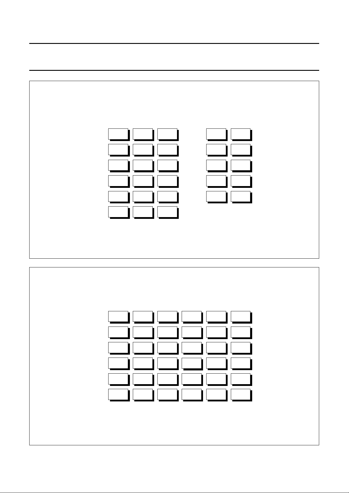
5.2 Keyboard
The PCD3330-1 is programmed to work with various
keyboards which can be connected to the sense column
inputs COL1 to COL6 and the scanning row outputs
ROW1 to ROW6. In this specification four examples are
given:
• Figure 2. The simplest keyboard. All basic functions are
available but only 2-key abbreviated dialling
(MEM + digit) is possible.
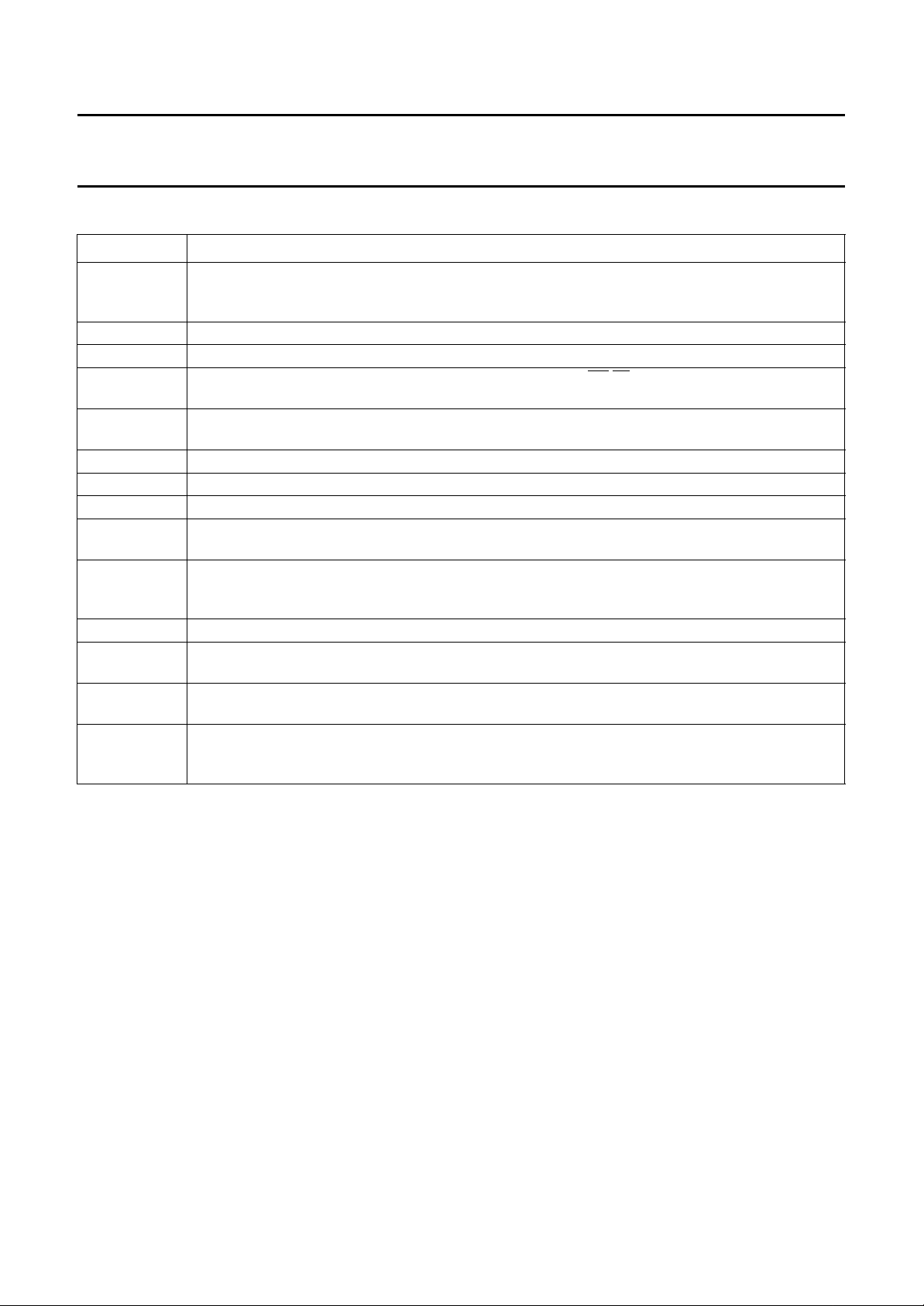
• Figure 3. As Fig.2 but with 3 extra 1-key abbreviated
dialling keys.
• Figure 4. As Fig.2 but the 10 repertory numbers can be
reached via M0 to M9 with 1-key abbreviated dialling.
• Figure 5. The most complex keyboard. A second
possibility for column 4 exists. This column can be
selected via EEPROM.
Keyboard entries are valid 20 ms (debounce time) after
the leading edge of a keyboard entry.
LINE TO EARTH CONNECTION
5.1.14 RVOL1
OUTPUTS
AND RVOL2/LSE, RINGER VOLUME
The RVOL1 and RVOL2 outputs can be used to control the
ringer output volume in four steps. The volume can be
changed via keyboard during ringing or conversation
mode (off-hook). The selected output level is stored in
EEPROM.
During on-hook dialling the RVOL2 output becomes the
LSE output for switching the listening-in amplifier.
When the on-hook dialling option is not selected and the
microphone mute option is active output LSE change to a
1997 Jan 15 7
Philips Semiconductors Product specification
Multistandard repertory dialler/ringer with
EEPROM
handbook, full pagewidth
ROW 1
ROW 2
ROW 3
ROW 4
ROW 5
ROW 6
COL 1
1
4
7
*
LNR
STO
COL 2
2
5
8
0
AP
MEM M
COL 3 COL 4 COL 5
FLASH
3
6
9
#
PCD3330-1
COL 6
MGG572
handbook, full pagewidth
ROW 1
ROW 2
ROW 3
ROW 4
ROW 5
ROW 6
Fig.2 Basic keyboard.
COL 1 COL 2 COL 3 COL 4 COL 5
1
4
7
*
LNR
STO MEM M E-1 E-2 E-3
AP
2
5
8
0
3
6
9
#
FLASH
COL 6
MGG573
Fig.3 Basic keyboard with 3 extra 1-key abbreviated dialling keys.
1997 Jan 15 8
Philips Semiconductors Product specification
Multistandard repertory dialler/ringer with
EEPROM
handbook, full pagewidth
ROW 1
ROW 2
ROW 3
ROW 4
ROW 5
ROW 6
COL 1 COL 2 COL 3 COL 4 COL 5
1
4
7
*
LNR
STO MEM M
AP
2
5
8
0
3
6
9
#
FLASH
M0
M2
M4
M6
M8
PCD3330-1
COL 6
M1
M3
M5
M7
M9
MGG574
handbook, full pagewidth
Fig.4 Basic keyboard with 10 extra 1-key abbreviated dialling keys.
ROW 1
ROW 2
ROW 3
ROW 4
ROW 5
ROW 6
COL 1 COL 2 COL 3 COL 4 COL 5
1
4
7
*
LNR
STO MEM M E-1 E-2 E-3
AP
2
5
8
0
3
6
9
#
FLASH
A/TONE
B/DIS
C/PR
D
HOOK
M0
M2
M4
M6
M8
COL 6
M1
M3
M5
M7
M9
MGG575
Fig.5 The most complex keyboard, option for column 4 is programmed into EEPROM.
1997 Jan 15 9
Philips Semiconductors Product specification
Multistandard repertory dialler/ringer with
PCD3330-1
EEPROM
Table 1 Function of the keys
SYMBOL DESCRIPTION
0to9,∗and # Standard keyboard. In pulse dialling mode the valid keys are the 10 numeric keys (0 to 9) − the
2 non-numeric dial keys (∗ and #) have no effect on the dialling. In DTMF dialling mode the
10 numeric keys and the 2 non-numeric dial keys are valid.
A to D If selected (EEPROM bit), these keys are only valid in DTMF dialling mode.
TONE If selected, pulse to DTMF switching key (mixed mode dialling).
DIS If selected (EEPROM bit), disconnect key will activate output
telephone set turns to the ON-HOOK state for this calibrated time.
PR If selected (EEPROM bit), program ringer key. With this key the ringer output volume and ringer
repetition rate can be changed.
M0 to M9 One key abbreviated dialling, the 10 repertory numbers are directly accessible via keys M0 to M9.
LNR Last number redial.
AP Access pause key, results in inserting an access pause in the telephone number.
FLASH FLASH/EARTH key, depending on the status programmed this key starts a FLASH or an EARTH
procedure.
HOOK Hook key (for on-hook dialling/loudspeaker on/off); as long as the handset stays on the cradle
activation of this key switches the set off-hook/on-hook. When the handset is not on the cradle
activation of this key switches the loudspeaker on/off (listening-in feature).
STO STORE key.
MEM Two-key abbreviated dialling (MEM + digit), the repertory numbers M0 to M9 are also accessible via
this two-key dialling procedure.
M Mute key, each time this key is pressed and dialling is not active, the mute output goes to HIGH or
LOW depending on the previous state.
E-1 to E-3 One key abbreviated dialling, three extra repertory numbers which are only directly accessible by
keys E-1 to E-3; these numbers can only be used when the repertory length is 16 digits
(programmable in EEPROM).
DP/FL for 800 ms. In this case the
1997 Jan 15 10
 Loading...