

Philips pca8521 DATASHEETS

INTEGRATED CIRCUITS
DATA SH EET
PCA8521
Infrared remote control transmitter
RC5
Product specification
Supersedes data of 1997 Jul 03
File under Integrated Circuits, IC02
1999 Jun 15

Philips Semiconductors Product specification
Infrared remote control transmitter RC5 PCA8521
FEATURES
• RC5 protocol
• Maximum of:
– 56 keys (20-pin version)
– 30 keys (16-pin version).
• Option of multi-system or single system transmitter
– Multi-system: maximum 8 systems, selection by key
– Single system: maximum 8 different systems per IC,
selection by jumper wire or switch.
• Power-down and key wake-up
• High output current (≤ 45 mA)
• Oscillator frequency of 432 kHz or 4 MHz
• Multiple key protection
• Option of 25% or 33% duty factor
• Contained in DIP16, SO16, DIP20 or SO20 packages.
ORDERING INFORMATION
TYPE
NUMBER
PCA8521FP DIP16
PCA8521FT SO16
PCA8521BP DIP20
PCA8521BT SO20
NAME DESCRIPTION VERSION
plastic dual in-line package; 16 leads (300 mil)
plastic small outline package; 16 leads; body width 7.5 mm
plastic dual in-line package; 20 leads (300 mil)
plastic small outline package; 20 leads; body width 7.5 mm
GENERAL DESCRIPTION
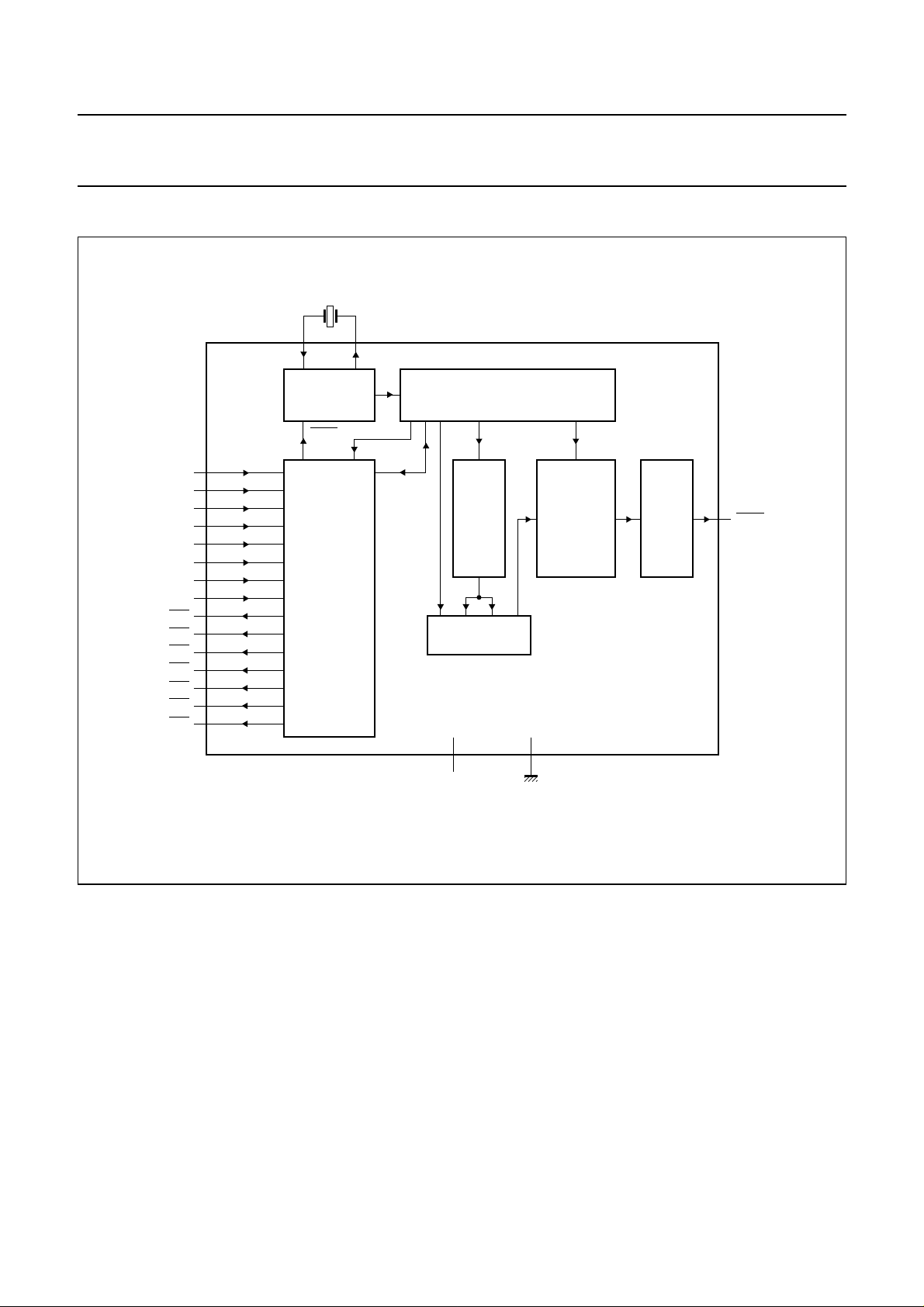
The PCA8521 can be used in infrared remote control
transmitters. It generates output pulses, in accordance
with the RC5 protocol, when a key is pressed. The IC does
not contain a software programmable processor.
However, it does contain a ROM in which the codes that
have to be transmitted are stored. An example of an
application diagram using a 20-pin IC is illustrated in Fig.7.
The oscillator frequency may be optionally chosen as
432 kHz or 4 MHz. For 432 kHz additional external
capacitors must be connected. The capacitors for a 4 MHz
oscillator is integrated. When a key in the key-matrix is
pressed a drive line will be connected to a sense line. This
causes the oscillator to start and a corresponding code will
be generated conforming to the RC5 protocol.
Seven drive lines (
(SN0 to SN7) may be connected via the key matrix to scan
the keys (see Fig.1).
When two or more keys are activated simultaneously no
transmission will take place.
PACKAGE
DR0 to DR6) and eight sense lines
SOT38-4
SOT162-1
SOT146-1
SOT163-1
1999 Jun 15 2
Philips Semiconductors Product specification
Infrared remote control transmitter RC5 PCA8521
BLOCK DIAGRAM
handbook, full pagewidth
SN0
SN1
SN2
SN3
SN4
SN5
SN6
SN7
DR0
DR1
DR2
DR3
DR4
DR5
DR6
432 kHz or 4 MHz
XTAL1 XTAL2
1
OSCILLATOR
STOP
4
5
6
7
9
10
8
3
16
15
14
13
12
11
17
SCANNING
KEY
2
TIMING GENERATOR
AND
CONTROL
36 kHz
1K x 8
ROM
SHIFT REGISTER
PULSE
GENERATOR
OUTPUT
DRIVER
19
LOUT
PCA8521
20
V
DD
18
V
SS
MBH038
Fig.1 Block diagram (for DIP20 and SO20 packages).
1999 Jun 15 3
Philips Semiconductors Product specification
Infrared remote control transmitter RC5 PCA8521
PINNING
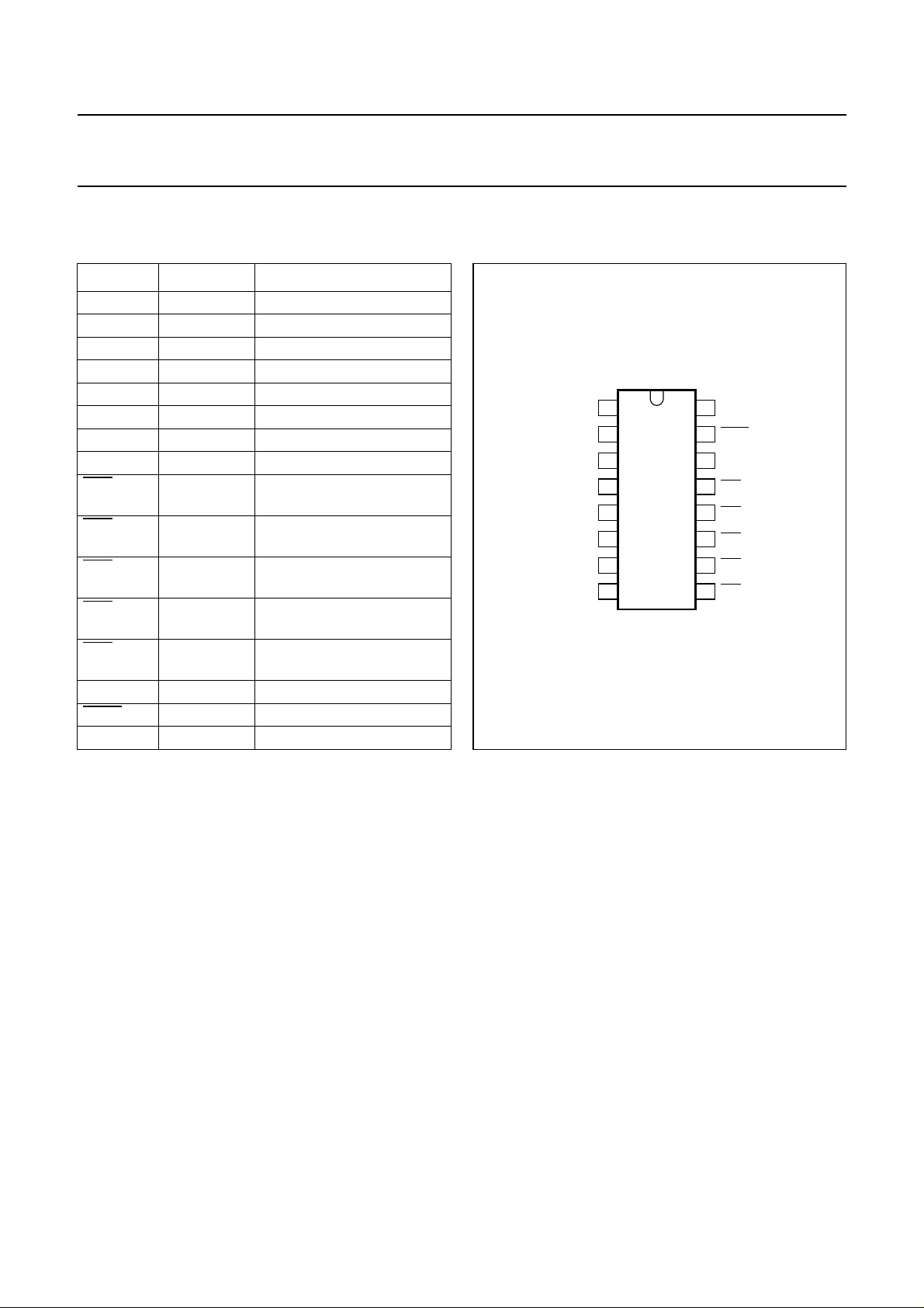
16-pin dual in-line and small outline package
SYMBOL PIN DESCRIPTION
XTAL1 1 oscillator input
XTAL2 2 oscillator output
SN0 3 sense line 0 for key matrix
SN1 4 sense line 1 for key matrix
SN2 5 sense line 2 for key matrix
SN3 6 sense line 3 for key matrix
SN4 7 sense line 4 for key matrix
SN5 8 sense line 5 for key matrix
DR4 9 drive line 4 for key matrix
(active LOW)
DR3 10 drive line 3 for key matrix
(active LOW)
DR2 11 drive line 2 for key matrix
(active LOW)
DR1 12 drive line 1 for key matrix
(active LOW)
DR0 13 drive line 0 for key matrix
(active LOW)
V
SS
14 ground
LOUT 15 output signal (active LOW)
V
DD
16 power supply
handbook, halfpage
Fig.2 Pin configuration (DIP/SO16).
XTAL1
XTAL2
SN0
SN1
SN2
SN3
SN4
SN5
1
2
3
4
5
6
7
8
PCA8521
MBH032
V
16
DD
LOUT
15
V
14
SS
13
DR0
12
DR1
DR2
11
DR3
10
DR4
9
1999 Jun 15 4
Philips Semiconductors Product specification
Infrared remote control transmitter RC5 PCA8521
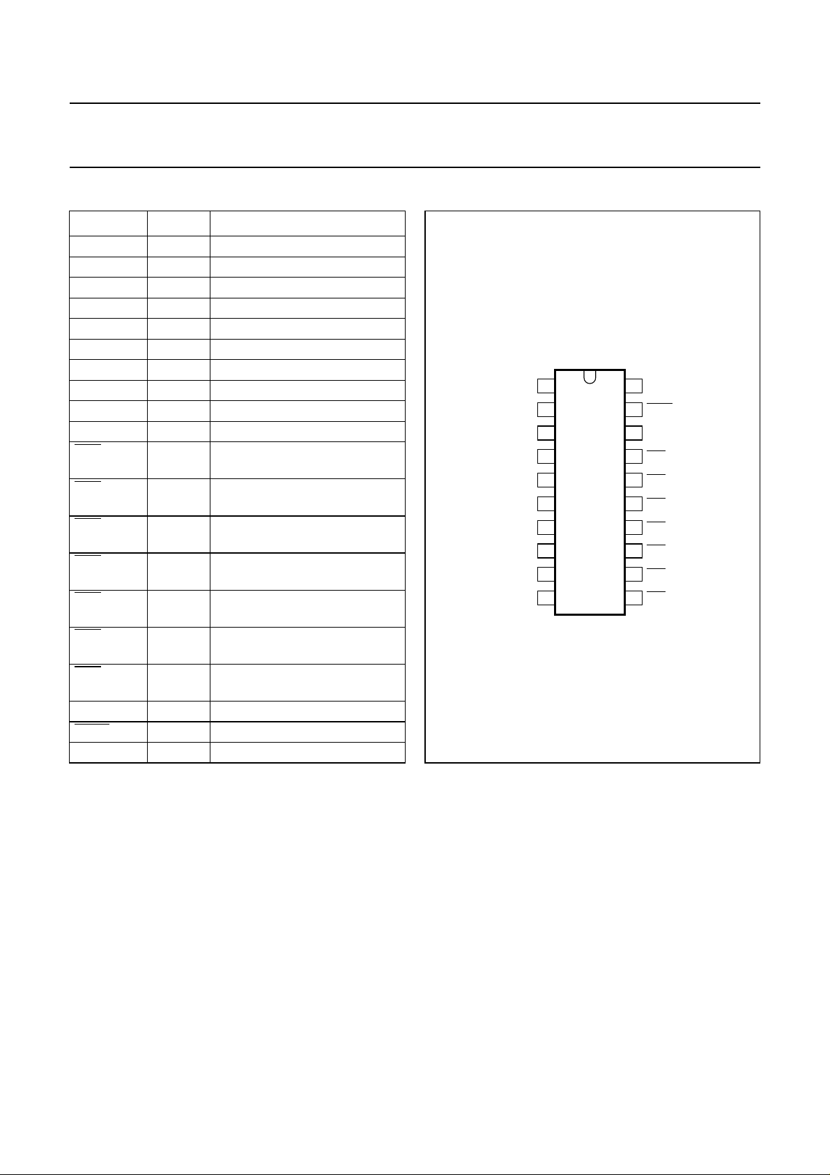
20-pin dual in-line and small outline package
SYMBOL PIN DESCRIPTION
XTAL1 1 oscillator input
XTAL2 2 oscillator output
SN7 3 sense line 7 for key matrix
SN0 4 sense line 0 for key matrix
SN1 5 sense line 1 for key matrix
SN2 6 sense line 2 for key matrix
SN3 7 sense line 3 for key matrix
SN6 8 sense line 6 for key matrix
SN4 9 sense line 4 for key matrix
SN5 10 sense line 5 for key matrix
DR5 11 drive line 5 for key matrix
(active LOW)
DR4 12 drive line 4 for key matrix
(active LOW)
DR3 13 drive line 3 for key matrix
(active LOW)
DR2 14 drive line 2 for key matrix
(active LOW)
DR1 15 drive line 1 for key matrix
(active LOW)
DR0 16 drive line 0 for key matrix
(active LOW)
DR6 17 drive line 6 for key matrix
(active LOW)
V
SS
18 ground
LOUT 19 output signal (active LOW)
V
DD
20 power supply
handbook, halfpage
Fig.3 Pin configuration (DIP/SO20).
XTAL1
XTAL2
SN7
SN0
SN1
SN2
SN3
SN6
SN4
SN5
1
2
3
4
5
6
7
8
9
10
PCA8521
MBH033
V
20
DD
19
LOUT
V
18
SS
17
DR6
16
DR0
15
DR1
14
DR2
13
DR3
DR4
12
DR5
11
1999 Jun 15 5

Philips Semiconductors Product specification
Infrared remote control transmitter RC5 PCA8521
FUNCTIONAL DESCRIPTION
Key numbering for the matrix is given in Tables 1 and 2.
Table 1 Key numbering for 16-pin package
DRIVER
LINES
DR0012345
DR1 8 9 10 11 12 13
DR2 16 17 18 19 20 21
DR3 24 25 26 27 28 29
DR4 32 33 34 35 36 37
Table 2 Key numbering for 20-pin package
DRIVER
LINES
DR0 01234567
DR1 8 9 10 11 12 13 14 15
DR2 16 17 18 19 20 21 22 23
DR3 24 25 26 27 28 29 30 31
DR4 32 33 34 35 36 37 38 39
DR5 40 41 42 43 44 45 46 47
DR6 48 49 50 51 52 53 54 55
SN0 SN1 SN2 SN3 SN4 SN5
SN0 SN1 SN2 SN3 SN4 SN5 SN6 SN7
SENSE LINES
SENSE LINES
When the keys have been scanned the key-number of the
activated key serves as the address of the ROM to obtain
the required code-word. When a 16-pin IC is used the
following sense lines and driver lines will not be connected;
SN6, SN7, DR5 and DR6. Consequently, key numbers 6,
7, 14, 15, 22, 23, 30, 31, 38, 39 and 40 to 55 will not be
addressed.
The ROM contains 8 banks of 64 code-words. Thus for
each key a maximum of 8 different code-words may be
generated. With multi-system use, 8 different systems
(e.g. TV, VCR, tuner, CD etc.) may be selected. Apart from
the system bits the command bits may also be different in
different banks (true multi-function keys). Selection can be
performed using the keys. For each key three bank select
bits are present that determine which bank will be selected
for the next key.
For each key an ‘inhibit’ bit is also present. When this bit is
at logic 1 at an address in a given bank, and when the
corresponding key is pressed (when this bank has been
selected) no transmission will take place.
1999 Jun 15 6
A single system option is available however, whereby
instead of keys a jumper wire and/or a switch may be used
for bank selection. Using this option it is possible to
program different transmitter models in one IC and select
the required bank by means of a jumper wire. Instead of a
jumper wire a side-switch may also be used to change the
generated code temporarily (select different bank) to
obtain multi-function keys. With this option the jumper
wires or switch must be connected between sense line
SN0 and one of the drive linesDR0toDR6 or ground. This
means that SN0 cannot be used to connect keys and the
maximum number of keys will be 25 keys for a 16-pin
package and 49 keys for a 20-pin package.
It is not possible to use a combination of jumper wires and
selection keys for bank selection in one unit.
The output of the ROM is loaded into a shift register that
provides the input bits for the pulse generator. This pulse
generator drives the output pin.
 Loading...