

Philips PCA84C923, PCA84C922 Datasheet

INTEGRATED CIRCUITS
DATA SH EET
PCA84C922; PCA84C923
Microcontrollers for universal
infrared remote transmitter
applications
Product specification
Supersedes data of 1995 Jun 30
File under Integrated Circuits, IC14
1997 Oct 22

Philips Semiconductors Product specification
Microcontrollers for universal infrared
remote transmitter applications
CONTENTS
1 FEATURES
2 GENERAL DESCRIPTION
3 ORDERING INFORMATION
4 BLOCK DIAGRAMS
5 PINNING INFORMATION
5.1 Pinning
5.2 Pin description
6 GENERAL OPERATION DESCRIPTION
6.1 System selection
6.2 Key scanning
6.3 Accessing command code
7 HARDWARE MODULATOR
7.1 ON-time Register
7.2 OFF-time Register
7.3 Pulse Timer
7.4 Pulse Counter
7.5 Hardware Modulator Control Register
(HMCTL)
7.6 Operation of the Hardware Modulator
8 CODING TABLE
8.1 Accessing the Coding Table
9 WATCHDOG TIMER (WDT)
10 PORT OPTIONS
11 INTERRUPTS
11.1 External keypad wake-up and T0/INT pin
interrupt
11.2 Hardware Modulator interrupt
11.3 Internal Timer/counter (T1) interrupt
12 DERIVATIVE REGISTERS
13 EMULATION
14 LIMITING VALUES
15 DC CHARACTERISTICS
16 AC CHARACTERISTICS
17 PACKAGE OUTLINES
18 SOLDERING
18.1 Introduction
18.2 SDIP
18.3 SO and VSO
19 DEFINITIONS
20 LIFE SUPPORT APPLICATIONS
PCA84C922; PCA84C923
1997 Oct 22 2
Philips Semiconductors Product specification
Microcontrollers for universal infrared
remote transmitter applications
1 FEATURES
• 84CXXX CPU
• ROM, RAM, I/O and keypad configurations are device
dependent; see Table 1
• Two test inputs: T0 and T1
• 3 single-level vectored interrupt sources:
– external (T0/INT and Port 1, for keypad press
Wake-up function)
– Timer/counter (TI)
– Hardware Modulator interrupt
• 8-bit programmable timer/counter with 5-bit prescaler
• Power saving Idle and Stop modes
• Low power operation: 2 V
• Hardware Modulator
• Watchdog timer
• On-chip oscillator: 1 to 6 MHz
• Single supply voltage: 2.0 to 5.5 V
• Operating temperature: −20 to +70 °C
• Available packages: SO24, SO28, VSO56 and SDIP24.
PCA84C922; PCA84C923
2 GENERAL DESCRIPTION
The PCA84C922A, PCA84C922C, PCA84C923A,
PCA84C923C and PCA84C923D are members of the
PCF84CXXXA CMOS family of microcontrollers and have
been designed for use in universal infrared remote
commander applications. The term PCA84C92X is used
throughout this data sheet to refer to all devices in the
range, differences between devices are shown in Table 1
and also highlighted in the text. In addition to the common
functions of the PCF84CXXXA family of microcontrollers
the PCA84C92X also provides:
• a Hardware Modulator that generates programmable
pulse trains for driving an infrared LED
• an on-chip Coding Table specifically for the storage of
code data
• a modified interrupt architecture that will wake-up the
CPU from the Idle or Stop modes when any key is
pressed
• a Watchdog Timer to prevent CPU lock-up.
The PCA84C923D has been designed as the emulation
chip for both the PCA84C92X and the PCA84CX22 range
of microcontrollers (both ranges being pin compatible).
Table 1 The PCA84C92X range of microcontrollers
FUNCTION PCA84C923D PCA84C923C PCA84C923A PCA84C922C PCA84C922A
System ROM 8 kbytes 8 kbytes 8 kbytes 8 kbytes 8 kbytes
System RAM 256 bytes 256 bytes 256 bytes 128 bytes 128 bytes
Coding Table ROM 16 kbytes 16 kbytes 16 kbytes 8 kbytes 8 kbytes
Coding Table extension up to 64 kbytes no no no no
Maximum number of keys 189 117 81 1 17 81
I/O 36 20 16 20 16
Emulation device PCA84C923D PCA84C923D PCA84C923D PCA84C923D PCA84C923D
Package VSO56 SO28 SO24 and SDIP24 SO28 SO24 and SDIP24
3 ORDERING INFORMATION
TYPE
NUMBER
PCA84C922AP SDIP24 plastic shrink dual in-line package; 24 leads (400 mil) SOT234-1
PCA84C922AT SO24 plastic small outline package; 24 leads; body width 7.5 mm SOT137-1
PCA84C922CT SO28 plastic small outline package; 28 leads; body width 7.5 mm SOT136-1
PCA84C923AP SDIP24 plastic shrink dual in-line package; 24 leads (400 mil) SOT234-1
PCA84C923AT SO24 plastic small outline package; 24 leads; body width 7.5 mm SOT137-1
PCA84C923CT SO28 plastic small outline package; 28 leads; body width 7.5 mm SOT136-1
PCA84C923DT VSO56 plastic very small outline package; 56 leads SOT190-1
NAME DESCRIPTION VERSION
PACKAGE
1997 Oct 22 3
Philips Semiconductors Product specification
Microcontrollers for universal infrared
remote transmitter applications
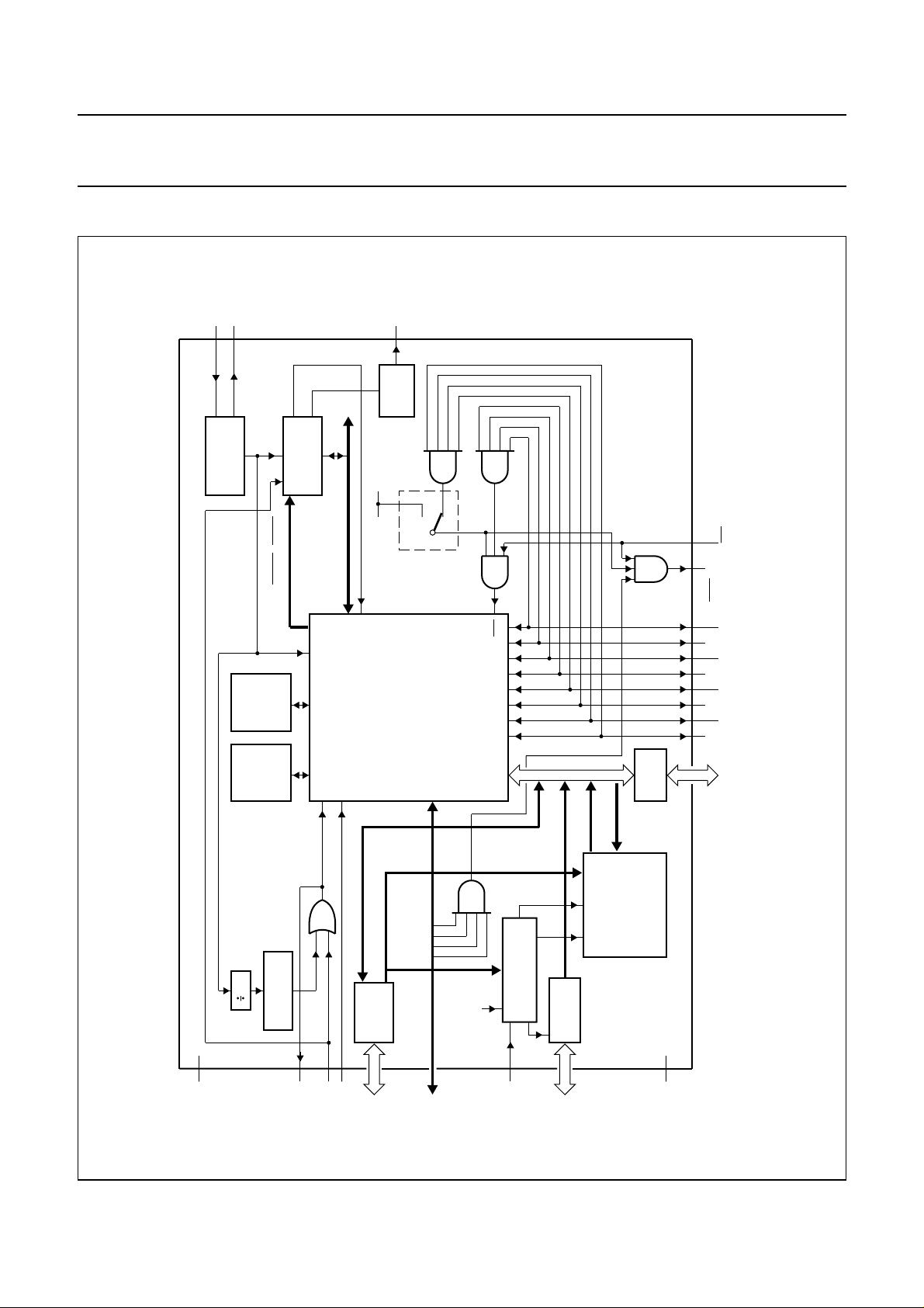
4 BLOCK DIAGRAMS
LOUT
DRIVER
OUTPUT
DD
V
metal option
andbook, full pagewidth
XTAL1
XTAL2
OSCILLATOR
ILOUT
HMINT
HARDWARE
MODULATOR
DAO to DA7
DXALE, DXWR, DXRD
T0/INT
PCA84C922; PCA84C923
MBE347
T0/INT
INTO
P10P12P14P16
P11P13P15P17
RAM
256 bytes
84CXX CORE
ROM
8 kbytes
DP65toDP60
OE
address (MSB)
30
TIMER
WATCHDOG
DD
V
RSTO
RESET
T1
LATCH
DPORT 6
DP67toDP60
DP67 to DP65
P23toP20
RDD5
CONTROL
CODING TABLE
LATCH
DPORT 5
EMU
DP57toDP50
PORT 0
(LSB)
address
ROM
16 kbytes
CODING TABLE
P07 to P00
Fig.1 Block diagram - PCA84C923D.
SS
V
1997 Oct 22 4
Philips Semiconductors Product specification
Microcontrollers for universal infrared
remote transmitter applications
XTAL1
XTAL2
OSCILLATOR
ILOUT
HMINT
HARDWARE
MODULATOR
DAO to DA7
LOUT
DRIVER
OUTPUT
DD
V
metal option
PCA84C922; PCA84C923
MBE413
T0/INT
DXALE, DXWR, DXRD
RAM
bytes
128/256
ROM
8 kbytes
30
TIMER
WATCHDOG
84CXX CORE
address (MSB)
LATCH
DPORT 6
DP67 to DP65
T0/INT
RDD5
DP65toDP60
CONTROL
CODING TABLE
EMU
ROM
OE
PORT 0
(LSB)
address
8/16 kbytes
CODING TABLE
P10P12P14P16
P11P13P15P17
handbook, full pagewidth
P07 to P00
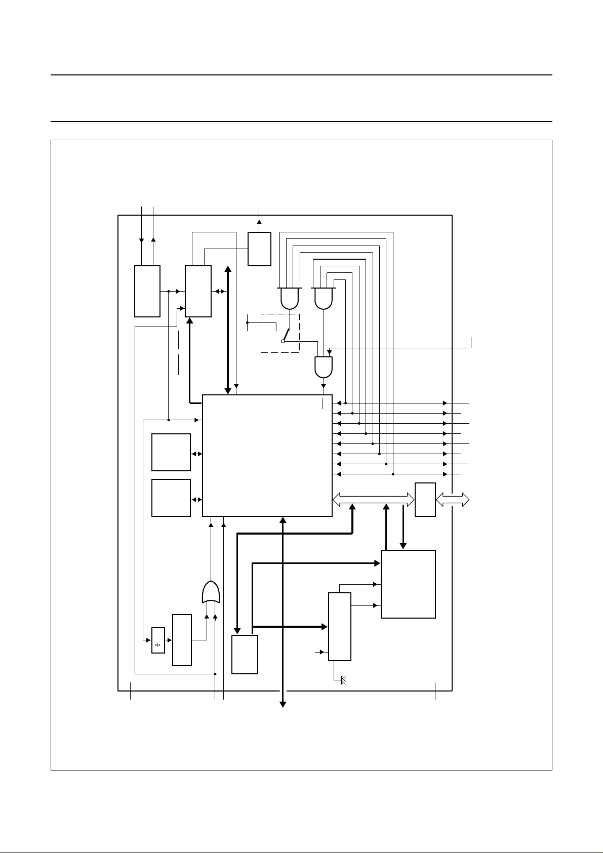
Fig.2 Block diagram - PCA84C922C and PCA84C923C.
DD
V
T1
RESET
P23toP20
1997 Oct 22 5
SS
V
Philips Semiconductors Product specification
Microcontrollers for universal infrared
remote transmitter applications
XTAL1
XTAL2
OSCILLATOR
ILOUT
HMINT
HARDWARE
MODULATOR
DAO to DA7
LOUT
DRIVER
OUTPUT
DD
V
metal option
PCA84C922; PCA84C923
MBE414
T0/INT
DXALE, DXWR, DXRD
RAM
bytes
128/256
ROM
8 kbytes
30
TIMER
WATCHDOG
84CXX CORE
address (MSB)
LATCH
DPORT 6
T0/INT
RDD5
DP65toDP60
CONTROL
CODING TABLE
EMU
ROM
OE
PORT 0
(LSB)
address
8/16 kbytes
CODING TABLE
P10P12P14P16
P11P13P15P17
handbook, full pagewidth
P07 to P00
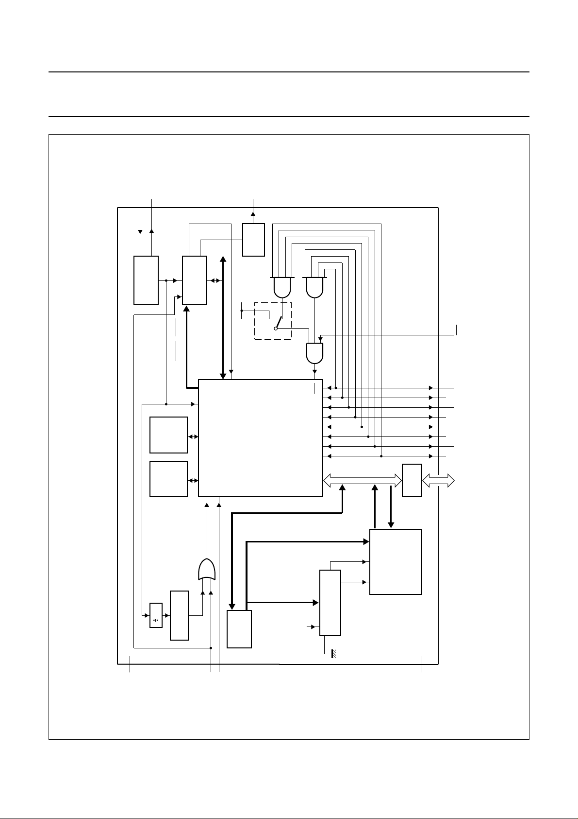
Fig.3 Block diagram - PCA84C922A and PCA84C923A.
DD
V
T1
RESET
1997 Oct 22 6
SS
V
Philips Semiconductors Product specification
Microcontrollers for universal infrared
remote transmitter applications
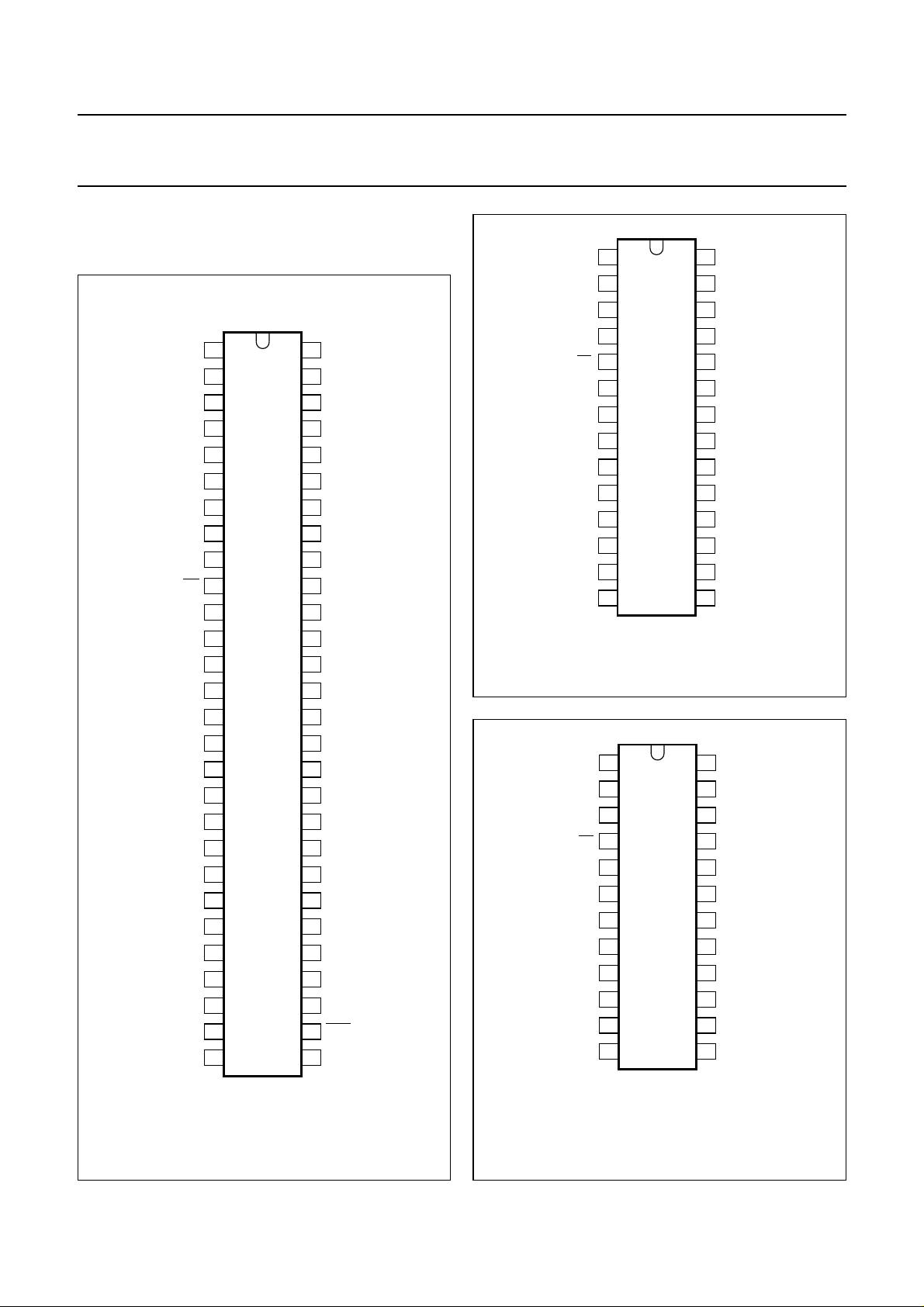
5 PINNING INFORMATION
5.1 Pinning
handbook, halfpage
RSTO
V
SS
P22
P14
DP57
P01
P00
n.c.
DP56
T0/INT
T1
DP55
RESET
DP54
DP53
V
DD
DP52
XTAL2
XTAL1
n.c.
n.c.
P04
DP51
P05
DP50
P16
P20
DP60
1
2
3
4
5
6
7
8
9
10
11
12
13
14
PCA84C923D
15
16
17
18
19
20
21
22
23
24
25
26
27
28
MBE343
P23
56
55
P15
DP67
54
EMU
53
P02
52
P03
51
50
n.c.
49
n.c.
n.c.
48
LOUT
47
V
46
SS
DP66
45
P10
44
DP65
43
42
DP64
41
P11
DP63
40
39
P12
P13
38
n.c.
37
36
n.c.
35
P07
P06
34
DP62
33
P17
32
DP61
31
INTO
30
P21
29
PCA84C922; PCA84C923
handbook, halfpage
RESET
Fig.5 Pin configuration of PCA84C922C
(SO28) and PCA84C923C (SO28).
handbook, halfpage
RESET
P22
P14
P01
P00
T0/INT
V
DD
XTAL2
XTAL1
P04
P05
P16
P20
P14
P01
P00
T0/INT
V
DD
XTAL2
XTAL1
P04
P05
P16
T1
T1
1
2
3
4
5
6
7
PCA84C922C
PCA84C923C
8
9
10
11
12
13
14
1
2
3
4
5
6
PCA84C922A
PCA84C923A
7
8
9
10
11
12
28
27
26
25
24
23
22
21
20
19
18
17
16
15
MBE342
24
23
22
21
20
19
18
17
16
15
14
13
MBE341
P23
P15
P02
P03
LOUT
V
SS
P10
P11
P12
P13
P07
P06
P17
P21
P15
P02
P03
LOUT
V
SS
P10
P11
P12
P13
P07
P06
P17
Fig.4 Pin configuration of PCA84C923D (VSO56).
1997 Oct 22 7
Fig.6 Pin configuration of PCA84C922A
(SO24/SDIP24) and PCA84C923A
(SO24/SDIP24).
Philips Semiconductors Product specification
Microcontrollers for universal infrared
PCA84C922; PCA84C923
remote transmitter applications
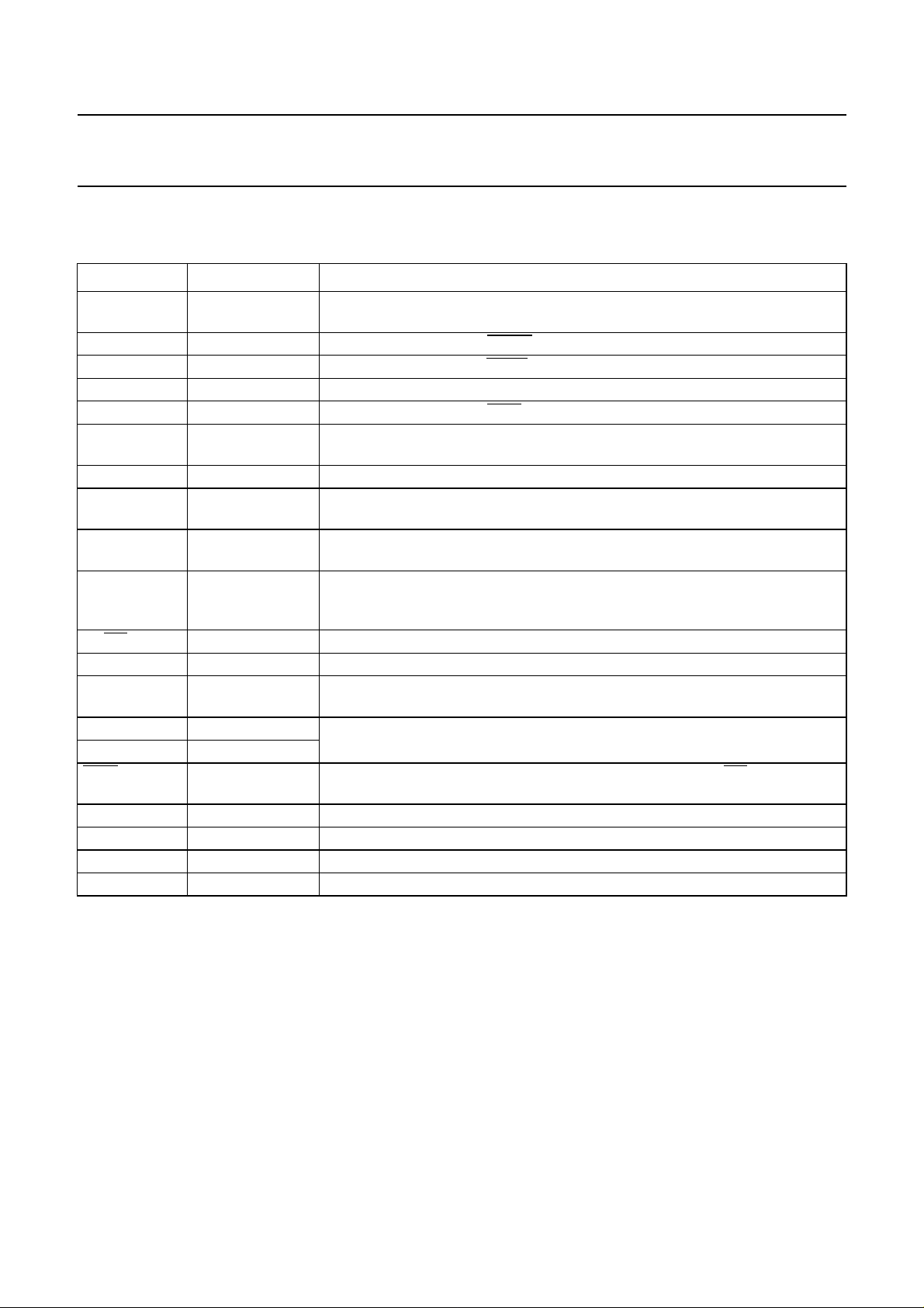
5.2 Pin description
Table 2 PCA84C923D (VS056)
SYMBOL PIN DESCRIPTION
P00 to P07 7, 6, 52, 51, 22,
24, 34 and 35
P10 44 Port line 10 or emulation
P11 41 Port line 11 or emulation
P12 39 Port line 12 or emulation DXALE signal input.
P13 38 Port line 13 or emulation
P14 to P17 4, 55, 26 and 32 Standard I/O port lines, generally used for keypad sensing, the wake-up function
P20 to P23 27, 29, 3 and 56 Standard I/O port lines with 10 mA sink capability.
DP50 to DP57 25, 23, 17, 15, 14,
12, 9 and 5
DP60 to DP67 28, 31, 33, 40, 42,
43, 45 and 54
RSTO 1 Used for emulation purposes only. This output is the result of the OR operation
T0/
INT 10 Test pin T0 or external interrupt input.
T1 11 Test pin T1 or timer/counter input (T1).
RESET 13 Active HIGH reset pin; normally connected to V
XTAL2 18 Crystal or ceramic resonator or LC oscillator connections.
XTAL1 19
INTO 30 Used for emulation purposes only and is connected to the T0/INT pin of the
LOUT 47 Pulse train output pin, capable of sinking 30 mA.
EMU 53 Emulation mode control pin; for normal operation this pin is connected to V
V
DD
V
SS
16 Power supply.
2 and 46 Ground.
Standard I/O Port lines, generally used for keypad scanning or for LSB address
lines of coding table.
DXWR signal input.
DXRD signal input.
EXDI signal input.
can be removed by mask option.
Standard I/O port lines, generally used for the data bus of Coding Table.
Standard I/O Port lines, generally used for keypad scanning or for MSB address
lines of Coding Table.
carried out internally on the RESET input and the Watchdog Timer reset and is
connected to the RESET pin of the 84C00.
as Power-on-reset serves the
SS
same function.
84C00.
SS
.
1997 Oct 22 8
Philips Semiconductors Product specification
Microcontrollers for universal infrared
PCA84C922; PCA84C923
remote transmitter applications
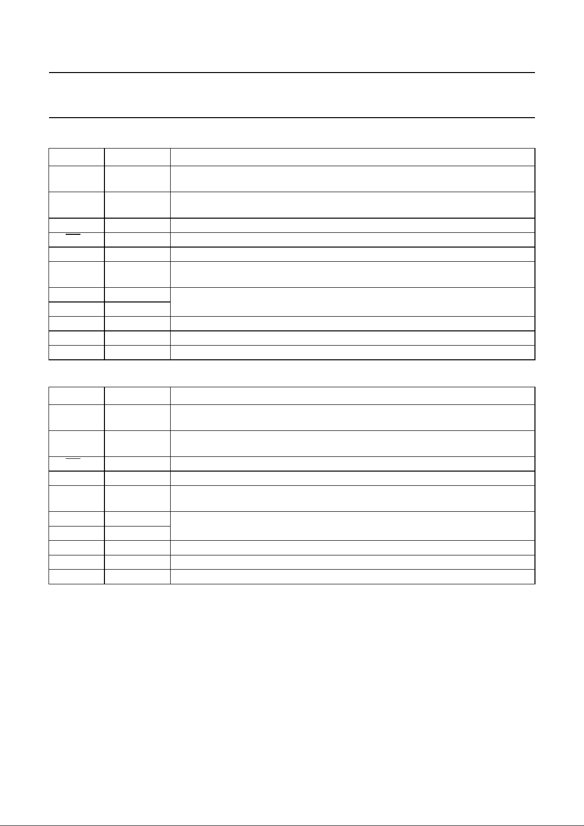
Table 3 PCA84C922C (SO28) and PCA84C923C (SO28)
SYMBOL PIN DESCRIPTION
P00 to P07 4, 3, 26, 25,
11, 12, 17, 18
P10 to P17 22, 21, 20, 19,
2, 27, 13, 16
P20 to P23 14, 15, 1, 28 Standard I/O port lines with 10 mA sink capability.
T0/
INT 5 Test pin T0 or external interrupt input.
T1 6 Test pin T1 or timer/counter input (T1).
RESET 7 Active HIGH reset pin; normally connected to V
XTAL2 9 Crystal or ceramic resonator or LC oscillator connections.
XTAL1 10
LOUT 24 Pulse train output pin, capable of sinking 30 mA.
V
DD
V
SS
8 Power supply.
23 Ground.
Standard I/O port lines, generally used for keypad scanning or for LSB address byte of
code data.
Standard I/O port lines, generally used for keypad sensing, the wake-up function of
P14 to P17 can be removed by mask option.
as Power-on-reset serves the same
SS
function.
Table 4 PCA84C922A (SO24/SDIP24) and PCA84C923A (SO24/SDIP24)
SYMBOL PIN DESCRIPTION
P00 to P07 3, 2, 23, 22,
10, 11, 14, 15
P10 to P17 19,18, 17, 16,
1, 24,12,13
T0/
INT 4 Test pin T0 or external interrupt input.
Standard I/O port lines, generally used for keypad scanning or for LSB address byte of
code data.
Standard I/O port lines, generally used for keypad sensing, the wake-up function of
P14 to P17 can be removed by mask option.
T1 5 Test pin T1 or timer/counter input (T1).
RESET 6 Active HIGH reset pin; normally connected to V
as Power-on-reset serves the same
SS
function.
XTAL2 8 Crystal or ceramic resonator or LC oscillator connections.
XTAL1 9
LOUT 21 Pulse train output pin, capable of sinking 30 mA.
V
DD
V
SS
7 Power supply.
20 Ground.
1997 Oct 22 9

Philips Semiconductors Product specification
Microcontrollers for universal infrared
remote transmitter applications
6 GENERAL OPERATION DESCRIPTION
The main application for the PCA84C92X is as a universal
infrared remote control commander and in this role the
PCA84C92X offers the complete solution in one chip.
The PCA84C92X can be programmed to generate code
data that conforms to any protocol (Philips, NEC, RCA,
Thomson and Siemens etc.) and is suitable for use in the
remote control of TVs, VCRs, audio equipment,
air-conditioning systems and in many other applications.
The ability of the PCA84C923D to access external
memory and therefore support more protocols, makes it an
extremely versatile device.
6.1 System selection
Different systems (TV or VCR etc.) can be controlled using
one universal infrared remote control commander;
switches can be used to select a specific system.
However, the PCA84C92X provides pin T1 for system
selection purposes and software is used to detect the
specific system. Port lines P14 to P17 can also be used for
system selection if their wake-up functions have not been
selected as a mask option.
PCA84C922; PCA84C923
After a Power-on-reset, the scan lines are set LOW and
the sense lines HIGH. If the system has entered the Stop
mode (by software) then when any key is depressed an
external interrupt will be generated and the system will be
woken-up.
If the external interrupt was enabled (by using the ‘EN I’
instruction) before the Stop mode was entered, then when
the CPU is woken-up, the instruction that follows the STOP
instruction will be executed before diverting to the interrupt
routine at vector address 03H. However, if the interrupt
was not enabled before the Stop mode was entered, then
when the CPU is woken-up the instruction that follows the
STOP instruction will be executed.
6.3 Accessing command code
When any key is depressed its function and operation
protocol are determined, then the command code is read.
If the command code is stored in system ROM it can be
accessed using the ‘MOVP A,@A’ instruction. If the
command code resides in Coding Table ROM it can be
accessed by writing the address to DP60 to DP67 (High
byte) and P00 to P07 (Low byte) and then reading the data
from DP50 to DP57.
When no key is pressed the scan lines (Port 0) can be
programmed HIGH and the sense lines (Port 1)
programmed LOW. If a diode is connected between a
sense line and scan line then the scan line will be pulled
LOW and this can be detected by a read operation to
Port 0.
6.2 Key scanning
Port lines P10 to P17 and T0/
be used as key sense lines. However, if the wake-up
option is not selected for ports P14 to P17 then these can
be used as general I/O lines.
Port lines P00 to P07, P20 to P23 and DP60 to DP67 can
be used as key scan lines or general I/O ports. Derivative
Port 6 also provides the High byte address for the Coding
Table, even when used as scan lines.
INT have been designed to
In Normal mode, if the Coding Table address is within the
0000 to 1FFFH range for PCA84C922 devices, or within
the 0000 to 3FFFH range for PCA84C923 devices, then
the internal Coding Table will be accessed when
Derivative Port 5 (address 05H) is read.
In the Normal mode only the PCA84C923D has the ability
to access external memory. If the Coding Table address is
greater than 3FFFH then the external memory will be
accessed when Derivative Port 5 (terminal) is read.
When the PCA84C923D is used in the Emulation mode,
when Derivative Port 5 is read, data will always be read
from DP50 to DP57 terminals. Therefore, the internal
Coding Table ROM can be emulated when the
PCA84C923D and the bond-out chip PCF84C00 are used.
1997 Oct 22 10
Philips Semiconductors Product specification
Microcontrollers for universal infrared
remote transmitter applications
handbook, full pagewidth
P00
P01
P02
P03
P04
P05
T1
V
DD
XTAL1
XTAL2
PCA84C922; PCA84C923
V
DD
system selection
100 Ω
R1
P06
PCA84C922A
P07
PCA84C923A
T0/INT
P10
P11
P12
P13
P14
P15
P16
P17
LOUT
RESET
V
3.0 V
30 mA
SS
MBE416
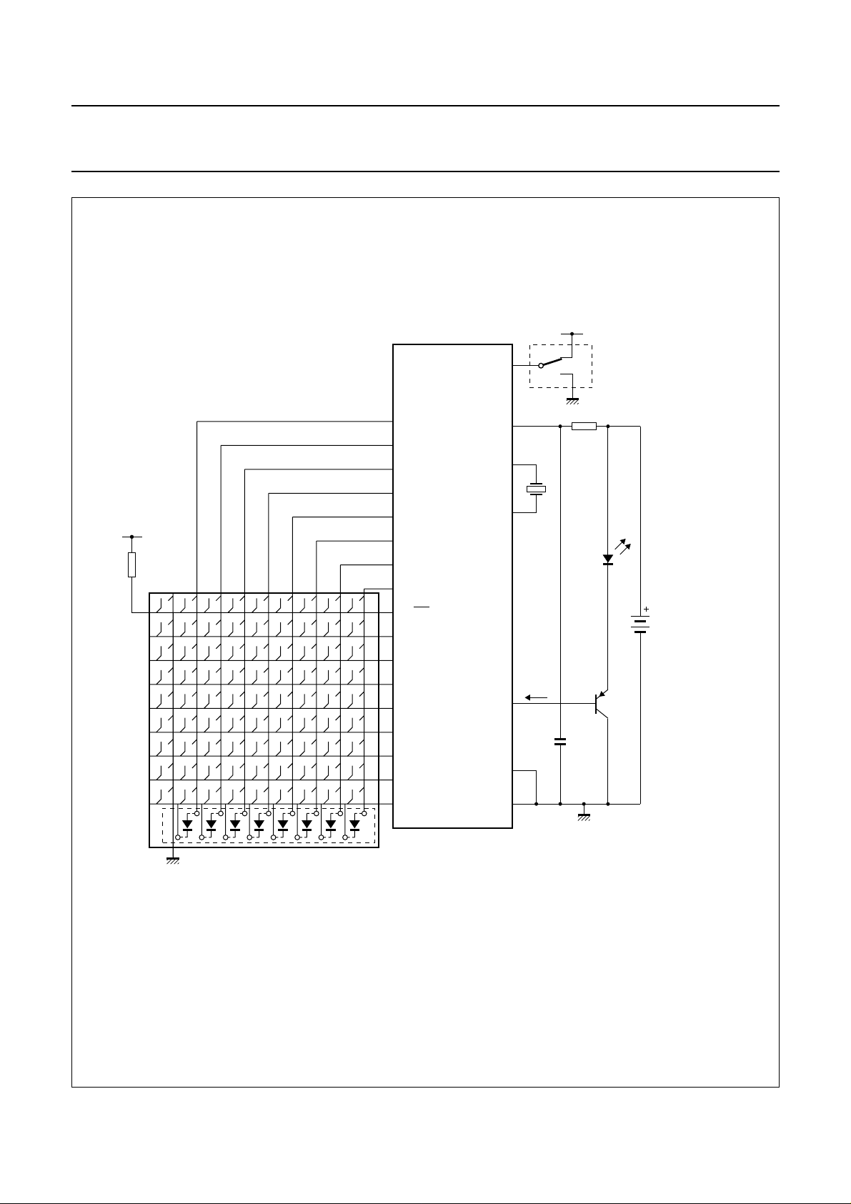
Fig.7 Typical Remote Control Transmitter application using the PCA84C922A or PCA84C923A.
1997 Oct 22 11
 Loading...