

Philips PCA84C122 Service manual

INTEGRATED CIRCUITS
DATA SH EET
PCA84C122; 222; 422; 622; 822
8-bit microcontrollers for
remote control transmitters
Product specification
Supersedes data of February 1994
File under Integrated Circuits, IC14
Philips Semiconductors
1995 May 01

Philips Semiconductors Product specification
8-bit microcontrollers for
remote control transmitters
CONTENTS
1 FEATURES
2 GENERAL DESCRIPTION
2.1 Important note
3 MEMORY AND I/O CONFIGURATIONS
4 ORDERING INFORMATION
5 BLOCK DIAGRAM
6 PINNING INFORMATION
6.1 Pinning
6.2 Pin description
7 POWER-ON-RESET STATUS AND PORT
OPTIONS
8 HARDWARE MODULATOR
8.1 Interface between the 84CXXX core and
derivative logic
8.2 Instructions for data transfer between the
84CXXX core and derivative logic
8.3 Operation of the Hardware Modulator
9 INTERRUPTS
9.1 Internal timer/counter
9.2 External keypad wake-up and T0/INT pin
10 OUTPUT DRIVER
11 WATCHDOG TIMER (WDT)
12 LIMITING VALUES
13 DC CHARACTERISTICS
14 AC CHARACTERISTICS
15 APPLICATION INFORMATION
16 PACKAGE OUTLINES
17 SOLDERING
17.1 Plastic small outline packages
17.2 Plastic dual in-line packages
18 DEFINITIONS
19 LIFE SUPPORT APPLICATIONS
PCA84C122; 222; 422; 622; 822
1995 May 01 2

Philips Semiconductors Product specification
8-bit microcontrollers for
remote control transmitters
1 FEATURES
• 84CXXX CPU
• ROM, RAM and I/O configurations are device
dependent; see Chapter 3
• Two test inputs: T0 (ANDed with Port 1 input lines)
and T1
• 3 single-level vectored interrupt sources:
– external (T0/INT and Port 1, for keypad press
wake-up function)
– timer/counter (TI)
– hardware modulator interrupt
• 8-bit programmable timer/counter with 5-bit pre-scaler
• Power saving: Idle and Stop modes are provided
• Hardware Modulator providing pulse bursts, with:
– programmable duty factor for each pulse
– programmable number of pulses
• One output line from the Hardware Modulator to control
the driver transistor for the infrared LED (IR-LED).
Capable of sinking 27 mA at V
• Watchdog Timer to keep the transmitter from being
locked or malfunction
• Available packages: SO and DIP types (SO20, SO24,
SO28, SDIP24 and DIP20); see Chapter 4
• On-chip oscillator: 455 kHz to 6 MHz
• Single supply voltage: 2.0 V to 5.5 V
• Operating temperature: −20 to +50 °C.
2 GENERAL DESCRIPTION
The PCA84C122 is a stand-alone microcontroller
designed for use in remote control transmitters for a wide
range of applications.
The PCA84C122 provides a number of dedicated
hardware functions for remote controller applications.
These functions include the following additional blocks to
the 84CXXX core:
• Interrupt Gate
• Hardware Modulator
• Output Driver
• Watchdog Timer.
= 2.0 V, V
DD
OUT
= 1.0 V
PCA84C122; 222; 422; 622; 822
Although the PCA84C122 is specifically referred to
throughout this data sheet, the information applies to all
the devices. The differences between the PCA84C122
and the other devices are specified in Chapter 3.
Figure 2 shows the general block diagram of the device.
The 84CXXX core plus 8 kbytes ROM and 64 bytes RAM
has the same function as described in the PCF84CXXX
family description (see
When the transmitter is not in use the microcontroller is in
Stop mode and the oscillator is halted. The AND gate
connected to the Port 1 (P10 to P17) lines provides the
wake-up to end the Stop mode.
The Hardware Modulator produces pulse bursts according
to the required protocol. The ON-time and OFF-time of
each pulse (i.e. duty factor) and the number of pulses are
controlled by software.
The Watchdog Timer (WDT) will reset the PCA84C122
when it has not been reloaded (reset) in time, because the
program has run out of sequence (endless loop,
continuous Idle mode, etc.). During Stop mode the
oscillator is halted, therefore the Watchdog Timer is not
running.
Automatic system reset is generated by the WDT if the
timer is not reset before overflow from counting within
a certain period of time.
The Output Driver can handle sufficient current to drive a
single transistor, that provides the required current for the
IR-LED.
2.1 Important note
This data sheet details the specific properties of the
PCA84C122; PCA84C222; PCA84C422; PCA84C622
and PCA84C822. The shared characteristics of the family
of microcontrollers are described in the PCF84CXXXA
Family single-chip 8-bit Microcontroller of
IC14”
, which should be read in conjunction with this data
sheet.
“Data Handbook IC14”
).
“Data Handbook
1995 May 01 3

Philips Semiconductors Product specification
8-bit microcontrollers for
remote control transmitters
3 MEMORY AND I/O CONFIGURATIONS
DEVICE I/O LINES ROM RAM
PCA84C122A 16
PCA84C122B 12
PCA84C222A 16
PCA84C222B 12
PCA84C422A 16
PCA84C422B 12
PCA84C622A 16
PCA84C622B 12
PCA84C622C 20
PCA84C822A 16
PCA84C822C 20
Note
1. 4 I/O lines with 10 mA sink capability.
(1)
(1)
PCA84C122; 222; 422; 622; 822
1K
2K
4K
6K
8KPCA84C822B 12
32 bytes
64 bytes
4 ORDERING INFORMATION
TYPE NUMBER
(1)
PACKAGE
NAME DESCRIPTION VERSION
PCA84CX22AP SDIP24 plastic shrink dual in-line package; 24 leads (400 mil) SOT234-1
PCA84CX22AT SO24 plastic small outline package; 24 leads; body width 7.5 mm SOT137-1
PCA84CX22BP DIP20 plastic dual in-line package; 20 leads (300 mil) SOT146-1
PCA84CX22BT SO20 plastic small outline package; 20 leads; body width 7.5 mm SOT163-1
PCA84C622CT
PCA84C822CT
SO28
plastic small outline package; 28 leads; body width 7.5 mm;
low stand-off height
SOT136-1
Note
1. ‘X’ in the type number denotes the numbers: 1, 2, 4, 6 and 8.
technology:
PC = CMOS
temperature range:
A = 20 to 50 C
PC
o
84C122
A
P
package:
P = plastic DIL
T = plastic mini-pack (SO)
generic type number
MLA973 - 1
Fig.1 Numbering scheme.
1995 May 01 4

1995 May 01 5
5 BLOCK DIAGRAM
remote control transmitters
Philips Semiconductors Product specification
8-bit microcontrollers for
V
DD
RESET
P20
P21
P22
P23
T1
XTAL1
XTAL
XTAL2
f / 30
osc
WDT
ROM
8 kbytes
RAM
64 bytes
PCA84CXXX
OSCILLATOR
HARDWARE
MODULATOR
84CXXX
CORE
T0/INT
OUTPUT
DRIVER
V
SS
MCD248 - 2
P00
P01
P02
P03
P04
P05
P06
P07
P10
P11
P12
P13
P14
P15
P16
P17
T0/INT
OUT
PCA84C122; 222; 422; 622; 822
Fig.2 Block diagram.
handbook, full pagewidth
Philips Semiconductors Product specification
8-bit microcontrollers for
remote control transmitters
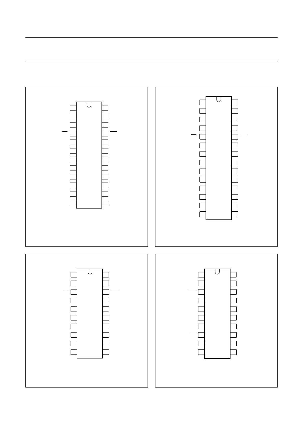
6 PINNING INFORMATION
6.1 Pinning
P14 P15
1
2
P01
P00
3
T0 / INT
RESET
4
T1
5
6
84CX22AP
V
DD
XTAL2
XTAL1
P04
P05
P16 P17
84CX22AT
7
8
9
10
11
12
MCD251 - 2
PCA84C122; 222; 422; 622; 822
1
24
P02
23
P03
22
21
OUT
V
20
SS
P10
19
P11
18
P12
17
P13
16
P07
15
P06
14
13
P22
2
P14
3
P01
4
P00
T0/INT
RESET
XTAL2
XTAL1
5
6
T1
7
84C622CT
V
DD
P04
P05
P16 P17
P20
84C822CT
8
9
10
11
12
13
MLA977 - 1
P23
28
P15
27
P02
26
P03
25
24
OUT
V
SS
23
P10
22
P11
21
P12
20
P13
19
P07
18
P06
17
16
P21
1514
Fig.3 Pin configurations PCA84CX22AP (SDIP24)
and PCA84CX22AT(SO24).
1
P01
2
P00
T1
V
DD
XTAL2
XTAL1
P04
P05
3
4
5
84CX22BT
6
7
8
9
10
T0 / INT OUT
RESET
19
18
17
16
15
14
13
12
11
MCD250 - 2
20
P02
P03
V
SS
P10
P11
P12
P13
P07
P06
Fig.4 Pin configuration PCA84CX22CT (SO28).
1
P10
V
SS
OUT
P03
P02
P01
P00
T0/INT
T1
RESET
2
3
4
5
84CX22BP
6
7
8
9
10
MLA975 - 2
20
P11
19
P12
P13
18
17
P07
P06
16
P05
15
P04
14
XTAL1
13
XTAL2
12
V
11
DD
Fig.5 Pin configuration PCA84CX22BT (SO20). Fig.6 Pin configuration PCA84CX22BP (DIP20).
1995 May 01 6

Philips Semiconductors Product specification
8-bit microcontrollers for
PCA84C122; 222; 422; 622; 822
remote control transmitters
6.2 Pin description Table 1 Pin description for PCA84CX22AP, PCA84CX22AT, PCA84CX22BP, PCA84CX22BT and PCA84CX22CT
PIN
SYMBOL
P00 to P07 3, 2, 23, 22,
P10 to P17 19, 18, 17, 16,
P20 to P23 − 14, 15, 1, 28 −−standard I/O Port lines, generally
INT4538test T0 and external interrupt input
T0/
T15649test T1 input
RESET 67510active HIGH reset;
SDIP24/SO24
(see Fig.3)
10, 11, 14, 15
1, 22, 12, 13
SO28
(see Fig.4)
4, 3, 26, 25,
11, 12, 17, 18
22, 21, 20,19,
2, 27, 13, 16
SO20
(see Fig.5)
2, 1, 20, 19, 9,
10, 11, 12
16, 15, 14, 13 1, 20,19, 18 standard I/O Port lines, generally
DIP20
(see Fig.6)
7, 6, 5, 4, 14,
15, 16, 17
standard I/O Port lines, generally
used for keypad scanning
used for keypad sensing
used for visible LED’s
normally connected to V
For further information see
PCF84CXXXA description in
“Data Handbook IC14”
XTAL1 9 10 8 13 crystal or ceramic resonator
XTAL289712
OUT 21 24 18 3 pulse train output pin, capable of
sinking 27 mA
V
DD
V
SS
78611power supply
20 23 17 2 ground
DESCRIPTION
.
SS
.
7 POWER-ON-RESET STATUS AND PORT OPTIONS
• All Port lines are standard I/O (option 1).
• RESET (Power-on-reset) level of 1.3 V.
After Power-on-reset, Port 0 is reset to LOW; Port 1, Port 2 and
1995 May 01 7
OUT are reset to HIGH.
Philips Semiconductors Product specification
8-bit microcontrollers for
remote control transmitters
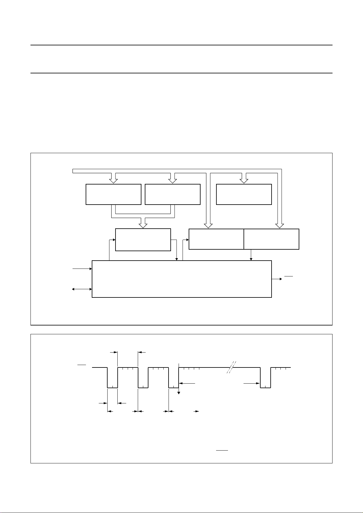
8 HARDWARE MODULATOR
The Hardware Modulator is the main derivative part in the
PCA84C122. Figure 7 shows the internal architecture.
The Hardware Modulator generates a pulse train whereby
the ON-time of a pulse and the OFF-time between pulses
can be programmed in a number of clock cycles
(period = 1/f
); see Figs 8 and 7.
osc
internal bus (IB0 – 7)
ON-TIME
REGISTER
(8)
OFF-TIME
REGISTER
(8)
PCA84C122; 222; 422; 622; 822
The number of pulses of the train is also programmable.
The time between pulse bursts is determined by software,
possibly using the standard 8-bit Timer/Counter.
8.1 Interface between the 84CXXX core and derivative logic
There are three (derivative) registers and one (derivative)
counter that must be loaded from the core.
CONTROL
REGISTER
(5)
f
osc
control
OUT
start
ON-time
PULSE TIMER
(8)
CONTROL LOGIC
Fig.7 Hardware Modulator.
OFF-time
end
interrupt
pulse #1 pulse #2 pulse #3
PULSE COUNTER
HIGH
(2)
elapse time by software
PULSE COUNTER
LOW
(8)
OUT
MCD255 - 1
MCD254
OFF-time = 4 (off-time register = 2)ON-time = 2 (on-time register = 0) number of pulses = 3
Fig.8 Example pulse train output of OUT pin.
1995 May 01 8
 Loading...