

Philips PCA1461U, PCA1462U-10 Technical data

查询PCA146x series供应商
INTEGRATED CIRCUITS
DATA SH EET
PCA146x series
32 kHz watch circuits with adaptive
motor pulse
Product specification
Supersedes data of 1998 Mar 18
File under Integrated Circuits, IC16
1998 Apr 21

Philips Semiconductors Product specification
32 kHz watch circuits with adaptive motor
pulse
FEATURES
• 32 kHz oscillator, amplitude regulated with excellent
frequency stability
• High immunity of the oscillator to leakage currents
• Time calibration electrically programmable and
reprogrammable (via EEPROM)
• A quartz crystal is the only external component required
• Very low current consumption; typically 170 nA
• Output for bipolar stepping motors of different types
• Up to 50% reduction in motor current compared with
conventional circuits, by self adaption of the motor pulse
width to match the required torque of the motor
• No loss of motor steps possible because of on-chip
detection of the induced motor voltage
• Detector for lithium or silver-oxide battery voltage levels
• Indication for battery end-of-life
• Stop function for accurate timing
• Power-on reset for fast testing
• Various test modes for testing the mechanical parts of
the watch and the IC.
GENERAL DESCRIPTION
The PCA146x series devices are CMOS integrated circuits
specially suited for battery-operated,
quartz-crystal-controlled wrist-watches, with a bipolar
stepping motor.
PCA146x series
ORDERING INFORMATION
TYPE
NUMBER
PCA1461U − chip in tray −
PCA1461U/10 − chip on foil −
PCA1462U − chip in tray −
PCA1462U/7 − chip with bumps on tape −
PCA1462U/10 − chip on foil −
PCA1463U − chip in tray −
PCA1463U/10 − chip on foil −
PCA1465U/10 − chip on foil −
PCA1465U/7 − chip with bumps on tape −
PCA1467U/10 − chip on foil −
Note
1. Figure 1 and Chapter “Package outline” show details of standard package, available for large orders only.
Chapter “Chip dimensions and bonding pad locations” shows exact pad locations for other delivery formats.
NAME DESCRIPTION VERSION
PACKAGE
(1)
1998 Apr 21 2

Philips Semiconductors Product specification
32 kHz watch circuits with adaptive motor
pulse
PINNING
SYMBOL PIN DESCRIPTION
V
SS
TEST 2 test output
OSC IN 3 oscillator input
OSC OUT 4 oscillator output
V
DD
M1 6 motor 1 output
M2 7 motor 2 output
RESET 8 reset input
FUNCTIONAL DESCRIPTION AND TESTING
The motor output delivers pulses of six different stages
depending on the torque required to turn the motor
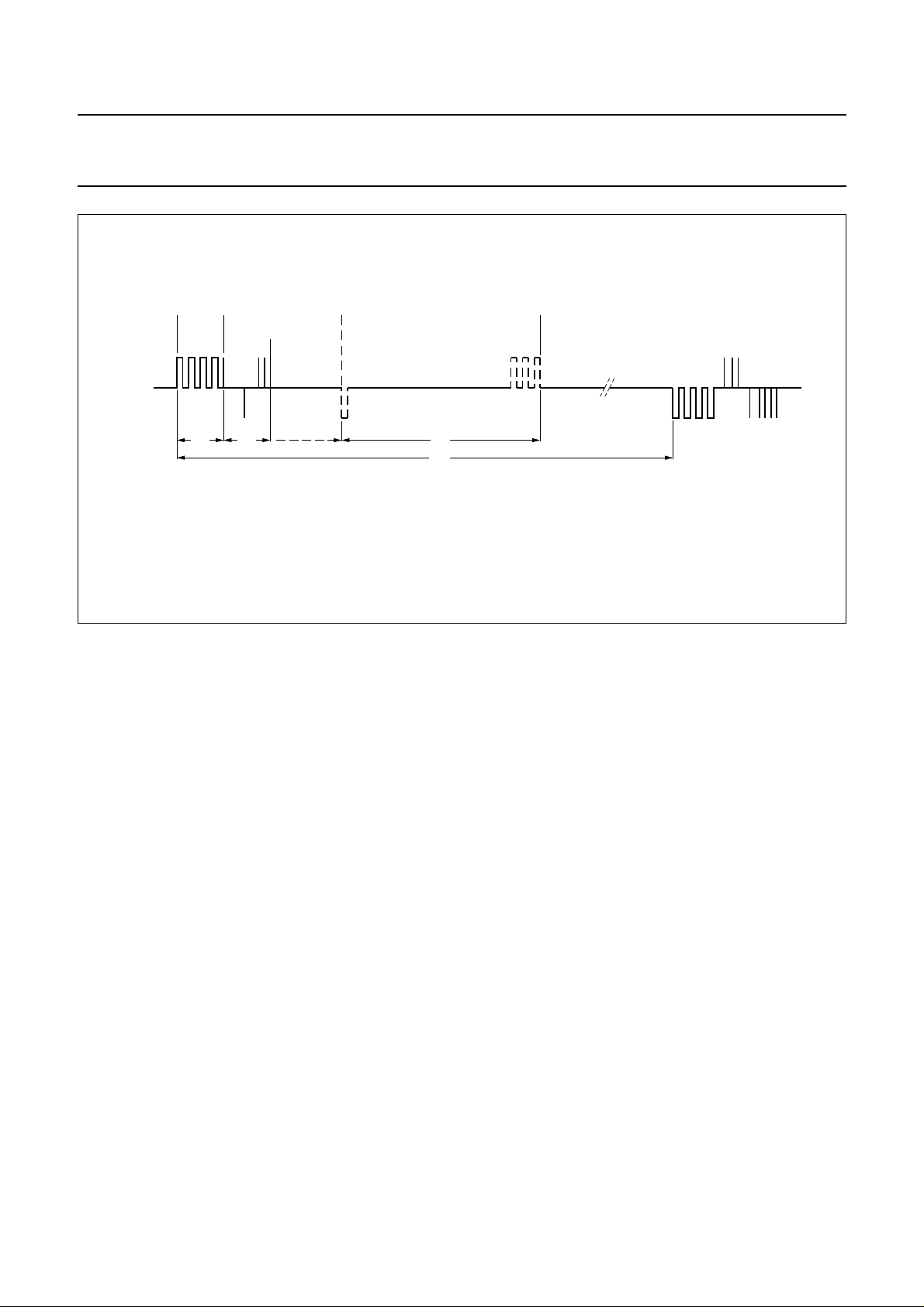
(Figs. 3 and 4). Every motor pulse is followed by a
detection phase which monitors the waveform of the
induced motor voltage. When a step is missed a correction
sequence will be started (Fig.2).
Motor pulses
The circuit produces motor pulses of six different stages
(stage 1 to 5, stage 8). Each stage has two independent
modes: silver-oxide and lithium. The voltage level of V
determines which mode is selected (see Section “Voltage
level detector”).
Stages 1 to 5 (both modes) are used in normal operation,
stage 8 occurs under the following conditions:
• Correction pulse after a missing step (both modes)
• End-of-life mode
• If stage 5 is not enough to turn the motor (both modes).
1 ground (0 V)
5 supply voltage
DD
PCA146x series
V
1
SS
TEST
2
PCA146xT
OSC IN
OSC OUT
3
4
Fig.1 Pin configuration, PCA146xT, (PMFP8).
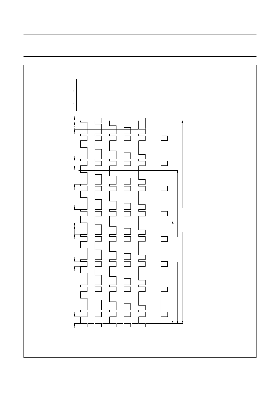
In the lithium mode, the ON state of the motor pulse is
reduced by 18.75% of the duty factor t
compensate for the increase in the voltage level.
After a RESET the circuit always starts and continues with
stage 1, when all motor pulses have been executed.
A failure to execute all motor pulses results in the circuit
going into stage 2, this sequence will be repeated through
to stage 8.
When the motor pulses at stage 5 are not large enough to
turn the motor, stage 8 is implemented for a maximum of
8 minutes with no attempt to keep current consumption
low. After stage 8 has been executed the procedure is
repeated from RESET.
The circuit operates for 8 minutes at a fixed stage, if every
motor pulse is executed. The next 480 motor pulses are
then produced at the next lower stage unless a missing
step is detected. If a step is missed a correction sequence
is produced and for a maximum of 8 minutes the motor
pulses are increased by one stage.
MSA937
8
7
6
5
RESET
M2
M1
V
DF
DD
(Fig.4) to
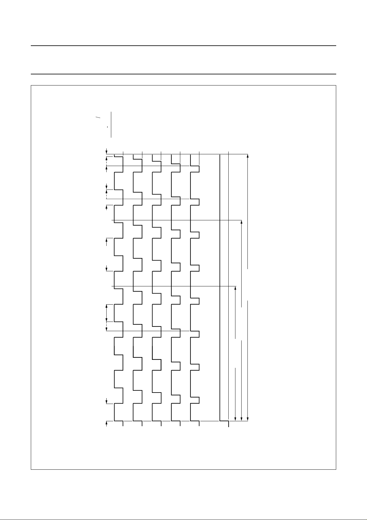
In the silver-oxide mode, the ON state of the motor pulse
varies between 56.25% and 100% of the duty factor
tDF= 977 µs depending on the stage (Fig.3). It increases
in steps of 6.25% per stage.
1998 Apr 21 3
Philips Semiconductors Product specification
32 kHz watch circuits with adaptive motor
pulse
V
M1 - M2
MOTOR
PULSE
t
P
DETECTION
t
D
POSSIBLE CORRECTION
SEQUENCE
t
C
t
T
PCA146x series
MSA942
Fig.2 Possible motor output waveform in normal operation with motor connected.
1998 Apr 21 4
Philips Semiconductors Product specification
32 kHz watch circuits with adaptive motor
pulse
DF
SOFF
DF
SON
t
tt
=
DF
tt
=
ON
t
ONL
t
SOFF
t
56.25 %
62.50 %
68.75 %
75.00 %
81.25 %
100.00 %
PCA146x series
MSA947
= 1.55 V).
DD
DF
t = 977 µs
SON
tt = 488 µs
SONF
P1
t = 7.81 ms
P2
t = 5.86 ms
P3
t = 3.9 ms
Fig.3 Motor pulses in the silver-oxide mode (V
This text is here in white to force landscape pages to be rotated correctly when browsing through the pdf in the Acrobat reader.This text is here in
_white to force landscape pages to be rotated correctly when browsing through the pdf in the Acrobat reader.This text is here inThis text is here in
white to force landscape pages to be rotated correctly when browsing through the pdf in the Acrobat reader. white to force landscape pages to be ...
1998 Apr 21 5
STAGE 1
STAGE 2
STAGE 3
STAGE 4
STAGE 5
STAGE 8
for stage 1to 5 = 488 µs − stage × 61 µs
OFF
t
for stage 1 to 5 = 488 µs + stage × 61 µs
ON
t
Philips Semiconductors Product specification
32 kHz watch circuits with adaptive motor
pulse
LOFF
t
DF
t
ON
t=
LOFF
t
DF
t
ONL
t
AOFF
t
37.50 %
43.75 %
50.00 %
56.25 %
62.50 %
81.25 %
PCA146x series
MSA946
= 2.1 V).
DD
µs
DF
t = 977
LOFF
t
AOFF
t = 183 µs
P1
t = 7.81 ms
P2
t = 5.86 ms
P3
t = 3.9 ms
Fig.4 Motor pulses in the lithium mode (V
This text is here in white to force landscape pages to be rotated correctly when browsing through the pdf in the Acrobat reader.This text is here in
_white to force landscape pages to be rotated correctly when browsing through the pdf in the Acrobat reader.This text is here inThis text is here in
white to force landscape pages to be rotated correctly when browsing through the pdf in the Acrobat reader. white to force landscape pages to be ...
1998 Apr 21 6
LONF
t = 244 µs
STAGE 1
STAGE 2
STAGE 3
STAGE 4
STAGE 5
STAGE 8
for stage 1 to 5 = 672 µs − stage × 61 µs
OFF
t
for stage 1 to 5 = 305 µs + stage × 61 µs
ON
t
Philips Semiconductors Product specification
32 kHz watch circuits with adaptive motor
pulse
Voltage level detector
The supply voltage is compared with the internal voltage
reference V
level detection is carried out 30 ms after RESET.
When a lithium voltage level is detected (VDD≥ V
circuit starts operating in the lithium mode (Fig.4).
When the detected VDD voltage level is between V
V
, the circuit operates in the silver-oxide mode (Fig.3).
EOL
If the battery end-of-life is detected (VDD<V
detection and stage control is switched OFF and the
waveform produced is an unchopped version of the
stage 8 waveform. To indicate this condition the waveform
is produced in bursts of 4 pulses every 4 s.
LIT
and V
every minute. The first voltage
EOL
EOL
LIT
LIT
), the
), the
and
PCA146x series
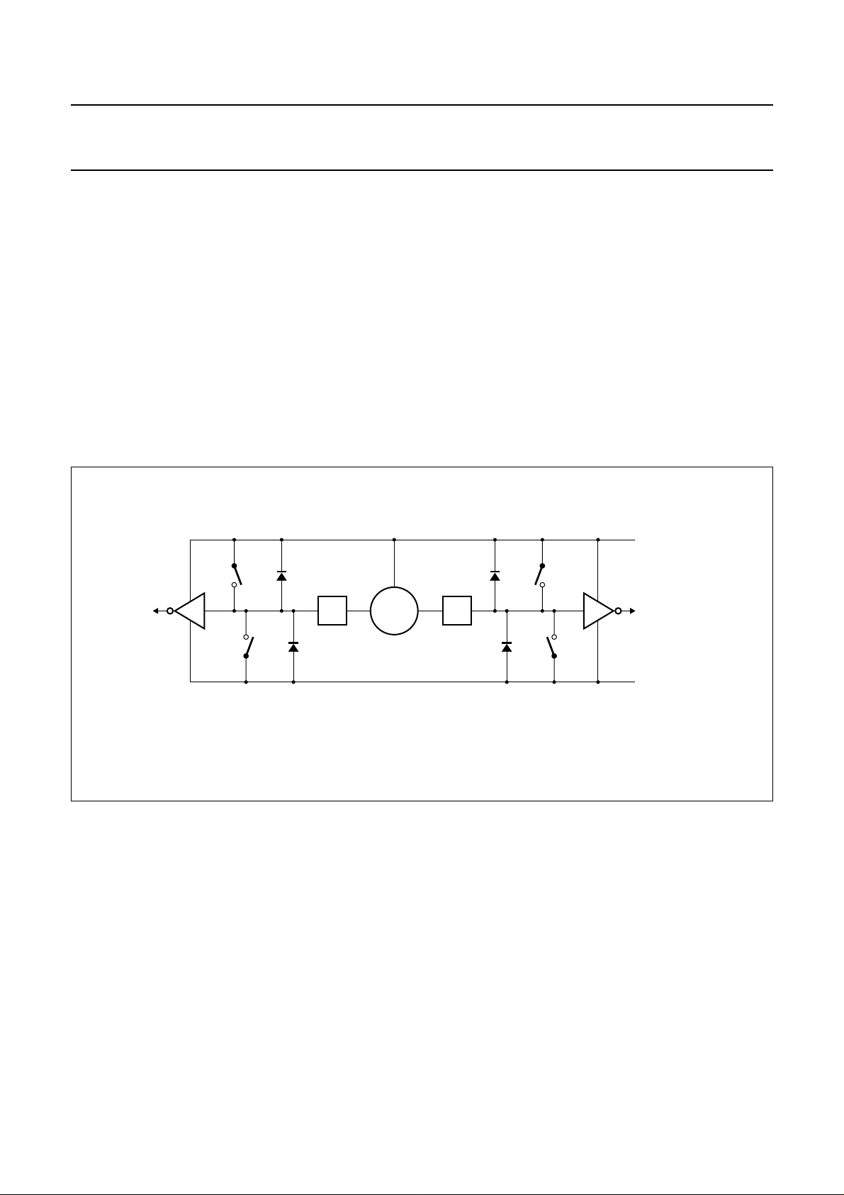
Detection of motor movement
After a motor pulse, the motor is short-circuited to VDD for
1 ms. Afterwards the energy in the motor inductor will be
dissipated to measure only the current generated by the
induced motor voltage. During the time tDI (dissipation of
energy time) all switches shown in Fig.5 are open to
reduce the current as fast as possible. The current will now
flow through the diodes D3 and D2, or D4 and D1. Then
the first of 52 possible measurement cycles (tMC) starts to
measure the induced current.
V
DD
P1 D1
L1 L2
N1 D3
MOTORM1 M2
P2D2
N2D4
Fig.5 Motor driving and detecting circuit.
MSA941
V
SS
1998 Apr 21 7

Philips Semiconductors Product specification
32 kHz watch circuits with adaptive motor
pulse
Detection criteria
The PCA146x uses current detection in two defined parts
of the detection phase to determine if the motor has moved
(refer to Figs 6 and 7). The detection criteria are:
part 1
• Minimum value of P = 1; where P = number of
measured positive current polarities after tDI.
part 2
• Minimum value of N = 2; where N = number of
measured positive current polarities since the first
negative current polarity after part 1 was detected
(see Fig.6).
If the opposite polarity is measured in one part, the internal
counter is reset, so the results of all measurements in this
part are ignored.
Table 1 Measurement cycle
PCA146x series
The waveform of the induced current must enable all these
measurements within the time t
motor pulse in order to be accepted as a waveform of an
executed motor pulse.
If the detection criterion is satisfied earlier, a measurement
cycle will not be started and the switches P1 and P2 stay
closed, the motor is switched to VDD.
Every measurement cycle (tMC) has 4 phases. These are
detailed in Table 1.
Note that detection and pulse width control will be switched
OFF when the battery voltage is below the end-of-life
voltage (V
), or if stage 5 is not sufficient to turn the
EOL
motor.
after the end of a positive
D
SYMBOL PHASE DESCRIPTION
t
M1
1 During tM1 the switches P1 and P2 are closed in order to switch the motor to VDD, so the
induced current flows unaffected through the motor inductance.
t
M2
2 Measures the induced current; during a maximum time tM2 all switches are open until a change
is sensed by one of the level detectors (L1, L2). The motor is short-circuited to VDD.
Depending on the direction of the interrupted current:
• The current flows through diodes D3 and D2, causing the voltage at M1 to decrease in relation
to M2;
• The current flows through diodes D4 and D1, causing the voltage at M2 to decrease in relation
to M1.
A successfully detected current polarity is normally characterized by a short pulse of
0.5 to 10 µs with a voltage up to ±2.1 V, failed polarity detection by the maximum pulse width of
61 µs and a voltage of ±0.5 V (see Fig.7).
t
M3
t
M4
3 The switches P1 and P2 remain closed for the time tM3.
4 If the circuit detects fewer pulses than P and N respectively, a pulse of the time tM4 occurs to
reduce the induced current. Therefore P2 and P1 are opened and N1 and N2 are closed.
Otherwise P1 and P2 remain closed.
1998 Apr 21 8
 Loading...