

Philips NN-SD681S, NN-SN661S, NN-SA661S, NN-SA651S, NN-SN651B Service Manual
...
© Panasonic Home Appliances Microwave Oven
(Shanghai) Co., Ltd. 2011.
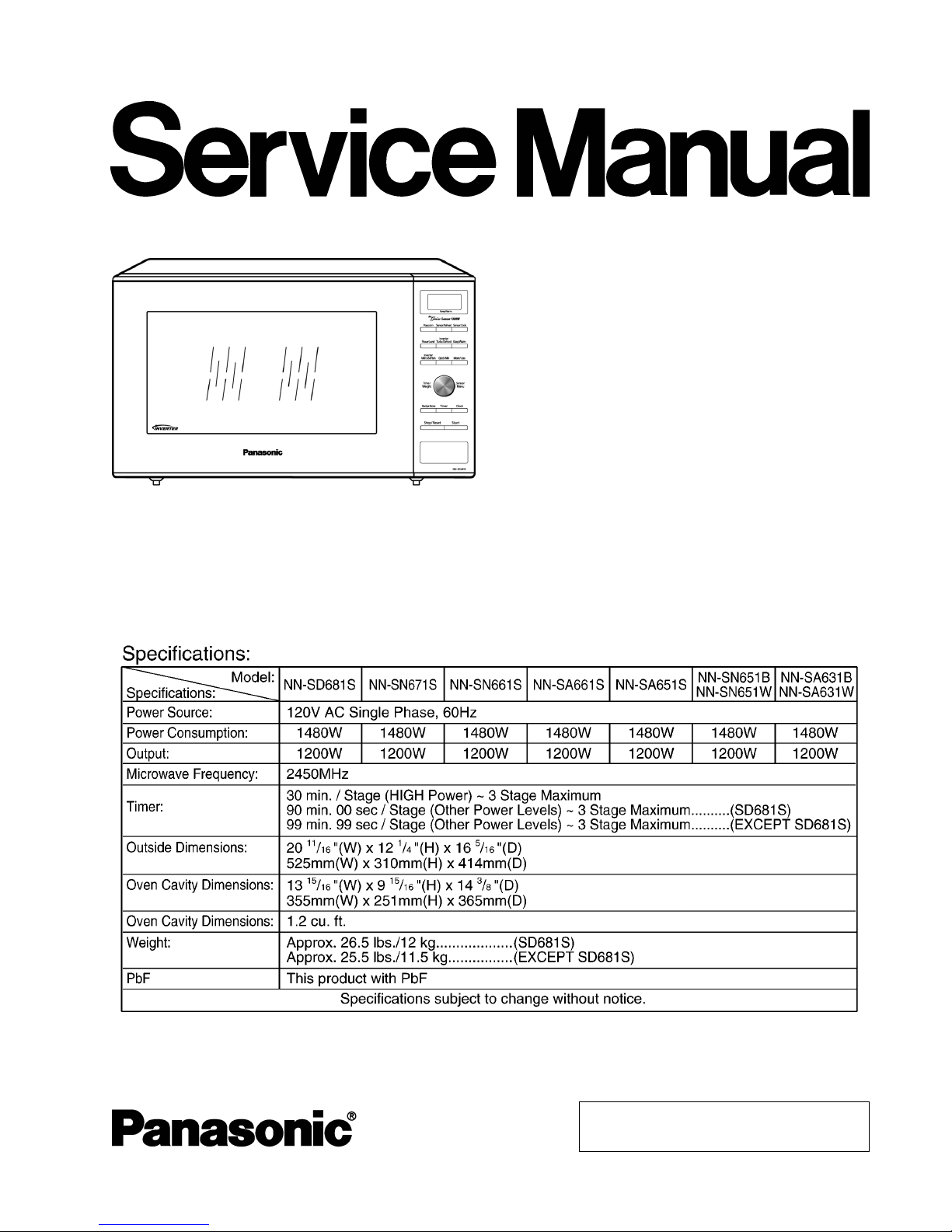
NN-SD681S
NN-SN671S
NN-SN661S
NN-SA661S
NN-SA651S
NN-SN651B
NN-SN651W
NN-SA631B
NN-SA631W
APH (USA)
Microwave Oven
ORDER NO.PHAMOS1105001CE
E1
2
NN-SD681S / NN-SN671S / NN-SN661S / NN-SA661S / NN-SA651S / NN-SN651B / NN-SN651W / NN-SA631B / NN-SA631W
3
NN-SD681S / NN-SN671S / NN-SN661S / NN-SA661S / NN-SA651S / NN-SN651B / NN-SN651W / NN-SA631B / NN-SA631W

1 SCHEMATIC DIAGRAM 5
1.1. NN-SD681S
5
1.2. EXCEPT NN-SD681S
6
2 DESCRIPTION OF OPERATING SEQUENCE
7
2.1. Variable power cooking control
7
2.2. Inverter power supply circuit
7
2.3. Inverter defrost
7
2.4. Sensor cooking (Only for sensor models)
7
2.5. Sensor reheat (Only for sensor models)
8
2.6. Steam sensor and digital programmer circuit (Only for
sensor models)
8
2.7. Thermistor
8
3 CAUTIONS TO BE OBSERVED WHEN TROUBLESHOOTING
9
3.1. Check the grounding
9
3.2. Inverter warnings
9
3.3. Part replacement.
10
3.4. When the 20A fuse is blown due to the malfunction of the
monitor switch:
10
3.5. Avoid inserting nails, wire etc. through any holes in the
unit during operation.
10
3.6. Verification after repair
10
3.7. Sharp edges
10
4 DISASSEMBLY AND PARTS REPLACEMENT PROCEDURE
11
4.1. Magnetron
11
4.2. Digital programmer circuit (D.P.C)
11
4.3. Low voltage transformer and/or power relays (RY1)
12
4.4. Fan motor
12
4.5. Door assembly
12
4.6. Turntable motor
14
4.7. Steam sensor (Only for sensor models)
14
4.8. Inverter power supply
15
5 COMPONENT TEST PROCEDURE
16
5.1. Primary, Secondary Interlock Switch & Power Relay RY1
16
5.2. Monitor Switch
16
5.3. Magnetron
16
5.4. key board membrane (Membrane switch assembly)
16
5.5. Inverter power supply (U)
17
6 MEASUREMENTS AND ADJUSTMENTS
18
6.1. Adjustment of primary interlock switch, secondary interlock
switch and monitor switch.
18
6.2. Measurement of microwave output
18
7 PROCEDURE FOR MEASURING MICROWAVE ENERGY
LEAKAGE
19
7.1. Equipment
19
7.2. Procedure for measuring radiation leakage
19
7.3. Record keeping and notification after measuremen t
19
7.4. At least once a year, have the radiation monitor checked
for calibration by its manufacturer.
20
8 TROUBLESHOOTING GUIDE
21
8.1. (Troubleshooting) Oven stops operation during cooking
22
8.2. (Troubleshooting) Other problems
23
8.3. Troubleshooting of inverter circuit (U) and magnetron
24
8.4. Trouble related to Digital Programmer Circuit
25
8.5. SIMPLE WAY OF H.V. INVERTER/MAGNETRON
TROUBLESHOOTING
27
8.6. H.V.INVERTER BOARD MAIN PARTS LIST
(F606Y8X00AP)
27
8.7. How to check the semiconductors using an OHM meter
28
9 EXPLODED VIEW AND PARTS LIST
29
9.1. EXPLODED VIEW
29
9.2. PARTS LIST
30
9.3. ESCUTCHEON BASE ASSEMBLY
31
9.4. DOOR ASSEMBLY
34
9.5. WIRING MATERIALS
35
9.6. PACKING AND ACCESSORIES
36
10 DIGITAL PROGRAMMER CIRCUIT
37
10.1. SCHEMATIC DIAGRAM (NN-SD681S)
37
10.2. SCHEMATIC DIAGRAM (EXCEPT NN-SD681S)
39
10.3. PARTS LIST
41
CONTENTS
Page Page
4
NN-SD681S / NN-SN671S / NN-SN661S / NN-SA661S / NN-SA651S / NN-SN651B / NN-SN651W / NN-SA631B / NN-SA631W

1 SCHEMATIC DIAGRAM
1.1. NN-SD681S
5
NN-SD681S / NN-SN671S / NN-SN661S / NN-SA661S / NN-SA651S / NN-SN651B / NN-SN651W / NN-SA631B / NN-SA631W

1.2. EXCEPT NN-SD681S
6
NN-SD681S / NN-SN671S / NN-SN661S / NN-SA661S / NN-SA651S / NN-SN651B / NN-SN651W / NN-SA631B / NN-SA631W
2.1. Variable power cooking
control
High Voltage Inverter Power Supply (U) controls output power
by the signal from Digital Programmer Circuit (DPC). Power
relay always stay on, but PWM (Pulse Width Modulation) signal
controls microwave output power.
NOTE:
The ON/OFF time ratio does not correspond with the
percentage of microwave power since approximately 2
seconds are required for heating of magnetron
filament.
Variable Power Cooking
POWER SETTING OUTPUT
POWER(%)
APPROX.
MANUAL MICROWAVE
DUTY
ON(SEC) OFF(SEC)
HIGH P10 100% 22 0
P9 90% 22 0
P8 80% 22 0
MEDIUM-HIGH P7 70% 22 0
MEDIUM P6 60% 22 0
P5 50% 22 0
P4 40% 22 0
MEDIUM-LOW P3 30% 22 0
P2 20% 15 7
P1 10% 8 14
2.2. Inverter power supply circuit
The Inverter Power Supply circuit powered from the line
voltage, 120V 60Hz AC input supplies 4,000V DC to the
magnetron tube, and functions in place of the H.V. transformer,
the H.V. capacitor and H.V. diode.
1. The AC input voltage 120V 60Hz is rectified to DC voltage
immediately.
2. DC voltage will be supplied to the switching devices called
IGBT. These devices are switched ON-OFF by the 20 to 40
kHz PWM (pulse width modulation) signal from the
microcomputer in the DPC.
3. This drives the High voltage transformer to increase voltage
up to 2,000V AC.
4. Then the half-wave doubler voltage rectifier circuit,
consisting of the H.V. diodes and capacitors, generates the
necessary 4,000V DC needed for the magnetron.
5. Output power of the magnetron tube is always monitored by
the signal output from the current transformer built into the
inverter circuit.
6. This signal is fed back to the microcomputer in the DPC to
determine operating conditions and output necessary to
control PWM signal to the Inverter Power Supply for control
of the output power.
2.3. Inverter defrost
When the Auto Control feature is selected and the Start pad is
tapped:
1. The digital programer circuit determines the power level and
cooking time to complete cooking and indicates the
operating state in the display window. Table shows the
corresponding cooking times for respective serving by
categories.
Inverter Turbo Defrost
SELECTED WEIGHT COOKING TIME
1.0 LB 4 min.00 sec.
2. When cooking time in the display window has elapsed, the
oven turns off automatically by a control signal from the
digital programmer circuit.
2.4. Sensor cooking (Only for
sensor models)
Auto sensor cooking without setting a power level or selecting
a time. All that is necessary is to select an Auto Sensor
Program before starting to cook.
Understanding Auto Sensor Cooking
As the food cooks, a certain amount of steam is produced.
If the food is covered, this steam builds up and eventually
escapes from the container. In Auto Sensor Cooking, a
carefully designed instrument, called the steam sensor
element, senses this escape of steam. Then, based upon
the Auto Sensor Program selected, the unit will
automatically determine the correct power level and the
proper length of time it will take to cook the food.
NOTE:
Auto Sensor Cooking is successful with the foods and
recipes found in the Auto Sensor Cooking Guide.
Because of the vast differences in food composition,
items not mentioned in the Cooking Guide should be
prepared in the microwave oven using power select
and time features. Please consult Variable Power
Microwave Cookbook for procedures.
2 DESCRIPTION OF OPERATING SEQUENCE
7
NN-SD681S / NN-SN671S / NN-SN661S / NN-SA661S / NN-SA651S / NN-SN651B / NN-SN651W / NN-SA631B / NN-SA631W
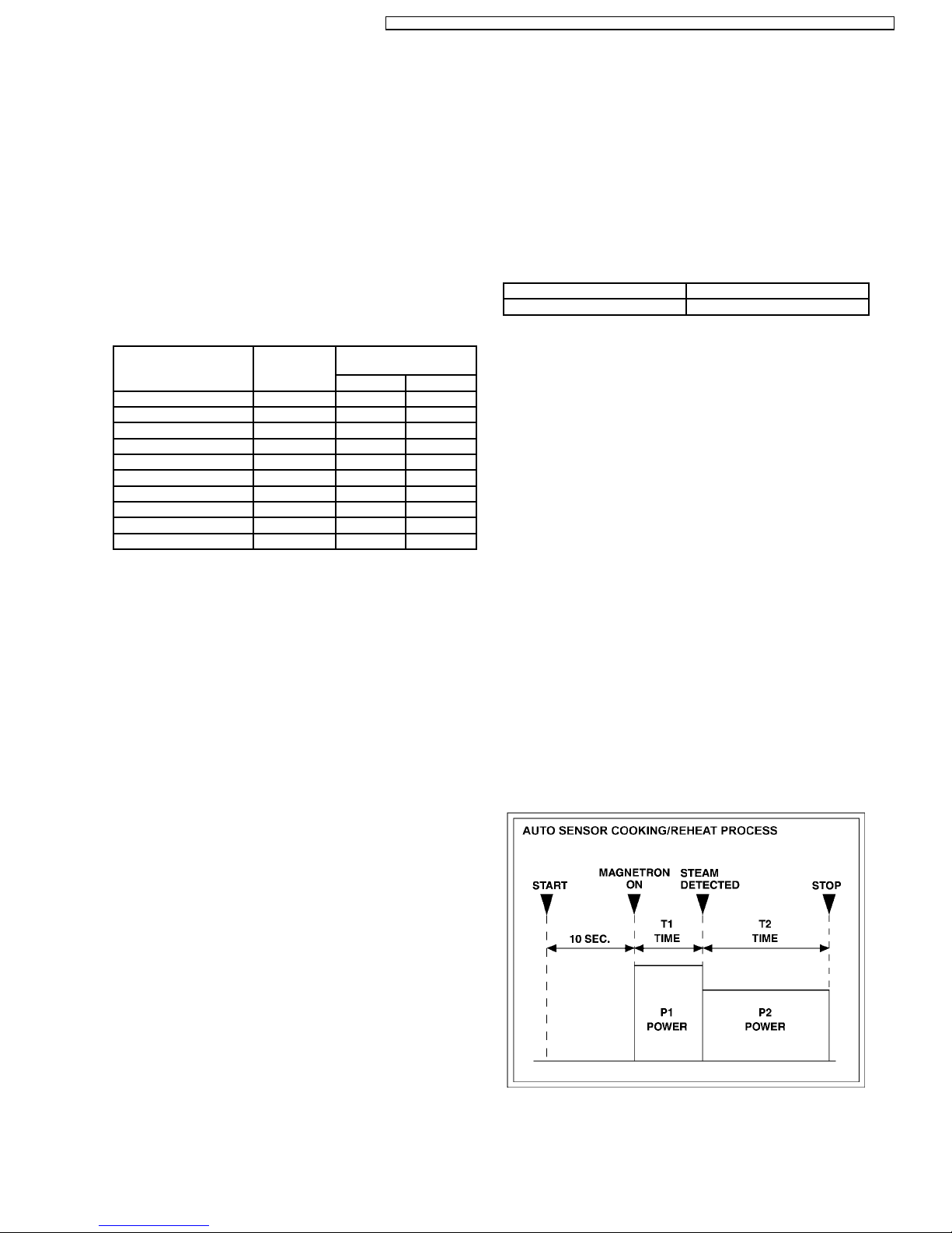
Explanation of the Auto Sensor Cooking process
1. During the first 10 second period there is no microwave
activity. When calculating the T2 time by using the
formula below make sure this 10 seconds is subtracted
from the T1 time. In other words, T1 time starts at the
end of the 10 second period.
2. T1 time The total amount of time it takes the microwave
oven to switch to T2 time after the 10second period.
3. T2 time When the steam escapes from the cooking
container placed in the oven, the steam sensor detects
it and the microprocessor calculates the balance of
cooking time. This T2 time is then shown in the display
and begins counting down.
Balance of cooking time (T2 time)
The balance of cooking time which is called T2 time,
can be calculated by the following formula.
T2 time (in sec.) = T1 time X K factor - 150
NOTE:
Remember, the T1 time starts after the 10 second
period. The coefficient K is programmed into the
microprocessor memory and they are listed in the
following tables along with the P1 and P2 powers.
NOTE:
When "More" or "Less" pad is selected, the K factor
varies resulting in T2 time to be increased or decreased.
Example of calculating the T2 time
Example 1: If the T1 time is measured to be 2 minutes and
40 seconds after the 10 second period.
T2 = T1 × K - 150 sec.
= 2 min. and 40 sec. × 1.1 - 150 sec.
= 160sec. × 1.1 - 150 sec.
= 26 sec.
Category P1
Power
P2
Power
K Factor
Standard
Oatmeal MEDIUM-HIGH MEDIUM-HIGH 0.4
2.5. Sensor reheat (Only for sensor
models)
Auto Sensor Reheat is a quick and easy way to reheat
refrigerated and room temperature foods.
Simply press the reheat pad. There is no need to select power
level and cooking time.
NOTE:
The Auto Sensor Reheat process is similar as Auto Sensor
Cooking process.
Balance of cooking time (T2 time)
The balance of cooking time which is called T2 time, can be
calculated by the following formula.
T2 time (in sec.) = T1 time X K factor - 150
NOTE:
Remember, the T1 time starts after the 10 second period.
The coefficient K is programmed into the microprocessor
memory and they are listed in the following tables along
with the P1 and P2 powers.
NOTE:
When "More" or "Less" pad is selected, the K factor varies
resulting in T2 time to be increased or decreased.
Example of calculating the T2 time
Example 1: If the T1 time is measured to be 2 minutes and
40 seconds after the 10 second period.
T2 = T1 × K - 150 sec.
= 2 min. and 40 sec. × 1.1 - 150 sec.
= 160sec. × 1.1 - 150 sec.
= 26 sec.
Category P1
Power
P2
Power
K Factor
Standard
Sensor Reheat MEDIUM-HIGH MEDIUM-HIGH 1.1
2.6. Steam sensor and digital
programmer circuit (Only for
sensor models)
In order to determine if the steam sensor function of the digital
programmer circuit is working, do the following test.
1. Place a water load (150 cc) in the oven.
2. Tap Sensor Reheat pad.
3. Tap Start pad.
4. Steam Sensor detects steam about 1.5 to 4 minutes after
the Start pad is tapped.
5. T1 time cooking automatically switches to remaining time
for cooking (T2).
6. The remaining cooking time (T2) appears in display
window. If the following cooking time appears, Steam
Sensor function is normal.
T1 TIME T2 TIME (Remainingcooking time)
50 Sec. ~ 12 Min. 0 Sec. ~ 10 Min.42 Sec.
2.7. Thermistor
The thermistor that is attached to the magnetron detects the
temperature of the magnetron and will stop magnetron
operation when overheating is detected. A normal thermistor´s
resistance is 35KΩ to 110KΩ for an ambient temperature range
of 10-30 degree C.
8
NN-SD681S / NN-SN671S / NN-SN661S / NN-SA661S / NN-SA651S / NN-SN651B / NN-SN651W / NN-SA631B / NN-SA631W
Unlike many other appliances, the microwave oven is a high
voltage, high current device. It is free from danger in ordinary
use, though extreme care should be taken during repair.
CAUTION
Servicemen should remove their watches and rings
whenever working close to or replacing the magnetron.
3.1. Check the grounding
Do not operate on a two wire extension cord. The microwave
oven is designed to be grounded when used. It is imperative,
therefore, to ensure the appliance is properly grounded before
beginning repair work.
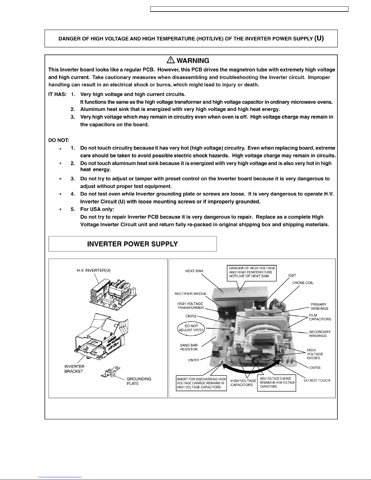
3.2. Inverter warnings
WARNING HIGH VOLTAGE AND HIGHTEMPERATURE
(HOT/LIVE) OF THE INVERTERPOWER SUPPLY (U)
The High Voltage Inverter Power Supply generates very
high voltage and current for the magnetron tube. Though it
is free from danger in ordinary use, extreme care should be
taken during repair.
The aluminum heat sink is also energized with high voltage
(HOT), do not touch when the AC input terminals are
energized. The power device Collector is directly connected
to the aluminum heat sink.
The aluminum heat sink may be HOT due to heat energy,
therefore, extreme care should be taken during servicing.
H.V. Inverter warning
WARNING FOR INVERTER POWER SUPPLY (U)
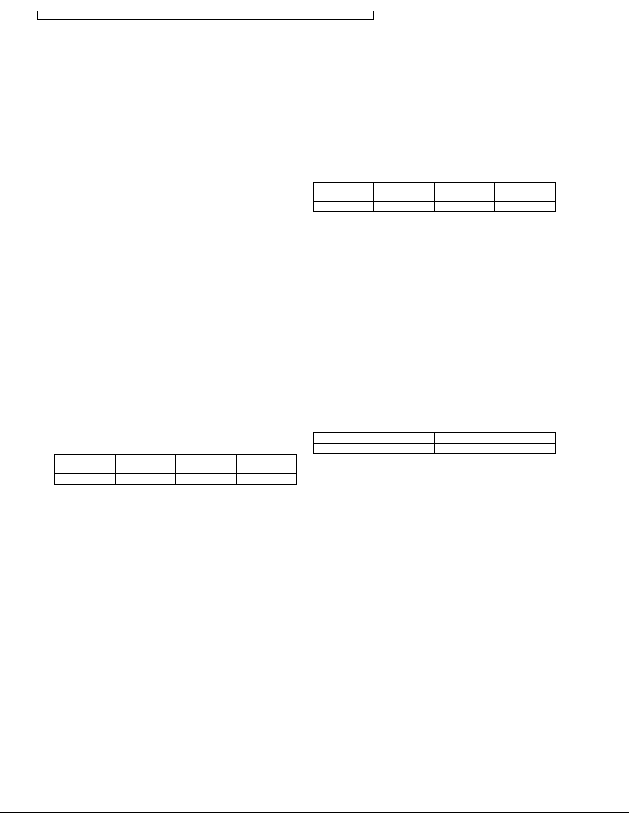
GROUNDING
Check the High Voltage Inverter Power Supply circuit
grounding. The high voltage inverter power supply circuit
board must have a proper chassis ground. The inverter
grounding plate must be connected to the chassis. If the
inverter board is not grounded it will expose the user to very
high voltages and cause extreme DANGER! Be sure that
the inverter circuit is properly grounded via the inverter
grounding plate.
Grounding of the inverter circuit board
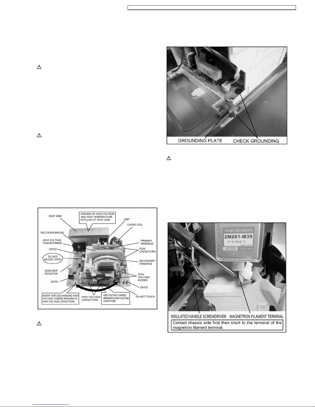
WARNING DISCHARGE THE HIGH VOLATGE
CAPACITORS
For about 30 seconds after the oven is turned off, an
electric charge remains in the high voltage capacitors of the
Inverter Power Supply circuit board.
When replacing or checking parts, remove the power plug
from the outlet and short the inverter output terminal of the
magnetron filament terminals to the chassis ground with an
insulated handle screwdriver to discharge. Please be sure
to contact the chassis ground side first and then short to the
output terminal.
3 CAUTIONS TO BE OBSERVED WHEN
TROUBLESHOOTING
9
NN-SD681S / NN-SN671S / NN-SN661S / NN-SA661S / NN-SA651S / NN-SN651B / NN-SN651W / NN-SA631B / NN-SA631W

Discharging the high voltage capacitors
WARNING
There is high voltage present with high current capabilities
in the circuits of the primary and secondary windings, choke
coil and heat sink of the inverter. It is extremely dangerous
to work on or near these circuits with the oven energized.
DO NOT measure the voltage in the high voltage circuit
including the filament voltage of the magnetron.
WARNING
Never touch any circuit wiring with your hand or with an
insulated tool during operation.
3.3. Part replacement.
When troubleshooting any part or component is to be replaced,
always ensure that the power cord is unplugged from the wall
outlet.
3.4. When the 20A fuse is blown
due to the malfunction of the
monitor switch:
WARNING
When the 20A 120V fuse is blown due to the malfunction of
the monitor switch, replace all of the components (primary
interlock switch, monitor switch and power relay RY1).
1. This is mandatory. Refer to “measurements and
adjustments” for the location of these switches.
2. When replacing the fuse, confirm that it has the
appropriate rating for these models.
3. When replacing faulty switches, be sure the mounting
tabs are not bent, broken or deficient in their ability to
hold the switches.
3.5. Avoid inserting nails, wire etc.
through any holes in the unit
during operation.
Never insert a wire, nail or any other metal object through the
lamp holes on the cavity or any holes or gaps, because such
objects may work as an antenna and cause microwave
leakage.
3.6. Verification after repair
1. After repair or replacement of parts, make sure that the
screws of the oven, etc. are neither loosen or missing.
Microwave energy might leak if screws are not properly
tightened.
2. Make sure that all electrical connections are tight before
inserting the plug into the wall outlet.
3. Check for microwave energy leakage. (Refer to procedure
for measuring microwave energy leakage).
CAUTION OF MICROWAVE RADIATION LEAKAGE
USE CAUTION NOT TO BECOME EXPOSED TO
RADIATION FROM THE MICROWAVE MAGNETRON OR
OTHER PARTS CONDUCTING MICROWAVE ENERGY.
IMPORTANT NOTICE
1. The following components have potentials above 2000V
while the appliance is operated.
• Magnetron
• High voltage transformer (Located on inverter (U))
• High voltage diodes (Located on inverter (U))
• High voltage capacitors (Located on inverter (U))
Pay special attention to these areas.
2. When the appliance is operated with the door hinges or
magnetron installed incorrectly, the microwave leakage
can exceed more than 5mW/cm
2
. After repair or
exchange, it is very important to check if the magnetron
and the door hinges are correctly installed.
3.7. Sharp edges
CAUTION
Please use caution when disassembling or reassembling
internal parts. Some exposed edges may be sharp to the
touch and can cause injury if not handled with care.
10
NN-SD681S / NN-SN671S / NN-SN661S / NN-SA661S / NN-SA651S / NN-SN651B / NN-SN651W / NN-SA631B / NN-SA631W
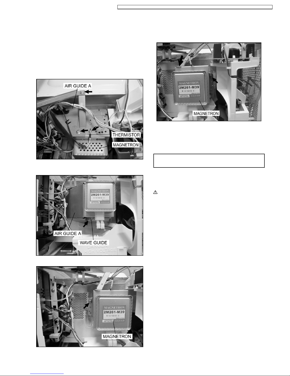
4.1. Magnetron
1. Discharge the high voltage capacitor.
2. Remove 1 screw holding air guide A on the magnetron.
3. Remove 1 screw holding air guide A on cavity top plate.
4. Remove 1 screws holding thermistor on the magnetron.
5. Remove 1 screw holding air guide A on the wave guide,
then remove the air guide A.
6. Remove 2 screws holding the magnetron.
NOTE:
After replacement of the magnetron, tighten mounting
screws properly, making sure there is no gap between
the waveguide and the magnetron to prevent
microwave leakage.
CAUTION
When replacing the magnetron, be sure the antenna gasket is in
place.
4.2. Digital programmer circuit
(D.P.C)
CAUTION:
Be sure to ground any static electric charge built up in
your body before handling the DPC.
1. Disconnect connector CN701 on H.V. Inverter board.
2. Remove 1 screw holding escutcheon base and slide the
escutcheon base upward slightly.
3. Remove all screws holding D.P.C. board on escutcheon
base.
4. Separate D.P.C board from tabs on the escutcheon base
and remove D.P.C board.
To replace membrane key board
5. Use tools such as kinfe etc. to lift the edge of escutcheon
sheet and peel off escutcheon sheet & key board
membrane completely from escutcheon base.
NOTE:
1. The membrane key board is attached to the
escutcheon base with double faced adhesive tape.
Therefore, applying hot air such as using a hair
dryer is recommended for smoother removal.
2. When installing the new key board membrane, make
sure that the surface of escutcheon base is clean to
prevent a malfunction or shorted contacts.
4 DISASSEMBLY AND PARTS REPLACEMENT
PROCEDURE
11
NN-SD681S / NN-SN671S / NN-SN661S / NN-SA661S / NN-SA651S / NN-SN651B / NN-SN651W / NN-SA631B / NN-SA631W
4.3. Low voltage transformer
and/or power relays (RY1)
CAUTION:
Be sure to ground any static electric charge built up in
your body before handling the DPC.
1. Replace D.P.C. board.
(A) Using solder wick or a desoldering tool and 30W
soldering iron carefully remove all solder from the terminal
pins of the low voltage transformer and/or power relays.
CAUTION:
Do not use a soldering iron or desoldering tool of
more than 30 watts on D.P.C. contacts.
(B) With all the terminal pins cleaned and separated from
D.P.C. contacts, remove the defective transformer/power
relays, Replace components making sure all terminal pins
are inserted completely resolder all terminal contacts
carefully.
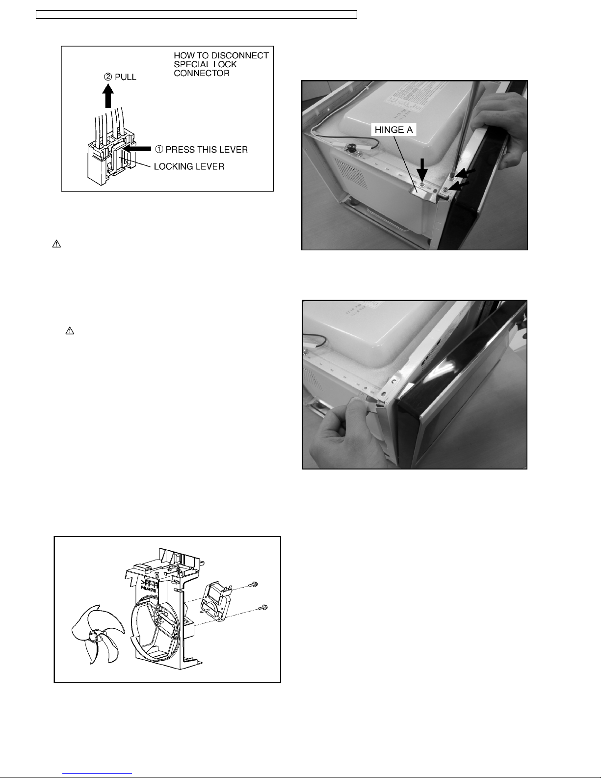
4.4. Fan motor
1. Disconnect 2 lead wires from fan motor terminals.
2. Remove 2 screws at location on oven attaching orifice
assembly.
3. Remove orifice assembly from oven assembly.
4. Remove fan blade from the fan motor shaft by pulling it
straight out.
5. Remove 2 screws holding fan motor to orifice.
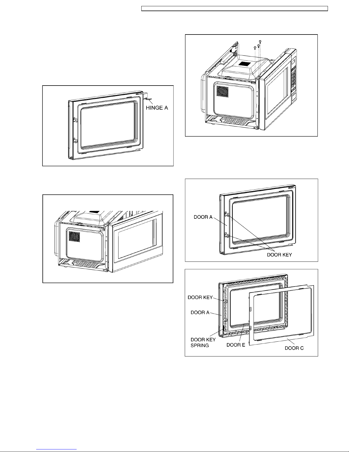
4.5. Door assembly
1. Support the door, remove 3 screws holding hinge A.
2. Open the door, remove door(U) and hinge A from cavity.
NOTE:
Support the door before opening.
3. Remove door C from door A (U) & door E by carefully
pulling outward starting from upper right hand corner using
a flat blade screwdriver.
4. Separate door E from tabs on door A (U) and remove door
A (U).
5. Remove door key and door key spring from door E.
12
NN-SD681S / NN-SN671S / NN-SN661S / NN-SA661S / NN-SA651S / NN-SN651B / NN-SN651W / NN-SA631B / NN-SA631W
6. Replace other components.
To re-install components:
NOTE:
After replacement of the defective component parts
of the door, reassemble it properly and adjustment
so as to prevent an excessive microwave leakage.
Adjustment of the door assembly (Refer page 18).
7. Place the hole of hinge A into the door’s upper hinge pin.
8. Use your left index finger to support the door’s lower hinge
pin while guiding the door’s hinge A into the cavity slot.
Then lower your finger to seat the door onto the hinge.
NOTE:
Door alignment is crucial. If door is misaligned,
apply pressure until alignment is achieved.
NOTE:
Adjust so that the upper portion of the door will
touch firmly to the oven cavity front plate, without
pushing the door. If the door assembly is not
mounted properly, microwave power may leak from
the clearance between the door and oven.
9. Tighten 2 mounting screws.
Be sure the gap between door E and cavity front plate will
be 0.3~0.7mm.
NOTE:
Always perform the microwave leakage measurement
test after installation and adjustment of door assembly.
13
NN-SD681S / NN-SN671S / NN-SN661S / NN-SA661S / NN-SA651S / NN-SN651B / NN-SN651W / NN-SA631B / NN-SA631W
 Loading...