

Page 1

Contents NICOL X-Ray Beam Limiting Device
Contents
1
INTRODUCTION AND TECHNICAL DATA..........................................................................................7
1.1 Introduction ...........................................................................................................................................7
1.2 Options..................................................................................................................................................7
1.3 Versions................................................................................................................................................8
1.4 Equipment Identification and Labelling..................................................................................................8
1.5 Tools .....................................................................................................................................................8
1.6 Technical Data......................................................................................................................................9
1.6.1 Compatibility......................................................................................................................................9
1.6.2 Mechanical Data..............................................................................................................................10
1.6.3 Electrical Data .................................................................................................................................10
1.6.4 Software Data..................................................................................................................................11
1.6.5 Environmental Conditions for Transport and Storage ......................................................................11
1.6.6 Performance Data ...........................................................................................................................12
1.7 Compliance information ......................................................................................................................13
1.8 Conditions of Acceptability ..................................................................................................................14
1.9 Abbreviations and definitions ..............................................................................................................14
1.10 Manual history .................................................................................................................................15
2
INSTALLATION..................................................................................................................................16
2.1 Introduction .........................................................................................................................................16
2.1.1 Tools & Test Equipment ..................................................................................................................16
2.1.2 Supplied Items.................................................................................................................................16
2.2 Installation instructions........................................................................................................................16
2.2.1 Mounting the coupling flange assembly Nicol V2.............................................................................17
2.2.2 Mounting the coupling flange assembly...........................................................................................18
2.2.3 Centering the BLD with respect to the X-Ray tube...........................................................................18
2.2.4 Mounting the BLD on the X-Ray tube housing.................................................................................19
2.2.5 Electrical installation........................................................................................................................20
2.2.6 Checking the alignment of the light field and the X-Ray field ...........................................................22
2.3 Options................................................................................................................................................22
2.3.1 Installation AEP-meter.....................................................................................................................22
3
FAULT FINDING.................................................................................................................................23
3.1 Introduction .........................................................................................................................................23
3.2 Faultfind Strategy................................................................................................................................24
3.3 Indicators ............................................................................................................................................24
3.3.1 LA2: Power Supply Converter CAN interface (PSC_CAN) ..............................................................24
3.3.2 LA3: Shutter Iris Filter Light Controller (SIFLCO).............................................................................25
3.3.3 Measuring Points.............................................................................................................................26
3.3.4 Miscellaneous..................................................................................................................................26
4
REPLACEMENTS ..............................................................................................................................28
4.1 General ...............................................................................................................................................28
4.2 Replace (complete) BLD on the stand.................................................................................................28
4.3 Replace Aesthetic Cover.....................................................................................................................28
(04.0) 5
9896 010
ALL RIGHTS RESERVED
2216.
2217.
2223.
2224.
Copyright © 2004 Philips Medical Systems Nederland B.V.
Page 2

NICOL X-Ray Beam Limiting Device Contents
Replace Field Indication Plate.............................................................................................................28
4.4
4.5 Replace DSC Buttons .........................................................................................................................29
4.6 Replace DSC assembly ......................................................................................................................29
4.7 Replace LA2: PSC_CAN.....................................................................................................................31
4.8 Replace LA3: SIFLCO.........................................................................................................................32
4.8.1 Replace PROM LA3D17..................................................................................................................32
4.9 Replace Electronic Ruler.....................................................................................................................33
4.9.1 Connection electronic ruler..............................................................................................................34
4.10 Replace Mechanical Ruler...............................................................................................................35
4.11 Replace Lamp .................................................................................................................................36
4.12 Replace Micro-switch ......................................................................................................................37
4.13 Replace Micro-switch including Bracket...........................................................................................37
4.14 Replace Fan ....................................................................................................................................38
5
PROGRAMMING................................................................................................................................39
5.1 Introduction .........................................................................................................................................39
5.2 Hardware Programming ......................................................................................................................39
5.2.1 LA1: Backpanel ...............................................................................................................................39
5.2.2 LA2: Power Supply Converter & CAN Interface Board (PSC_CAN) ................................................39
5.3 Software Programming .......................................................................................................................39
6 ADJUSTMENTS .................................................................................................................................40
6.1 Centering the BLD with the X-Ray Tube .............................................................................................40
6.1.1 Introduction......................................................................................................................................40
6.1.2 Tools Required ................................................................................................................................40
6.1.3 Mounting the BLD Alignment Tool ...................................................................................................40
6.1.4 Checking the centering for PEI 9896 010 2216. ..............................................................................40
6.1.5 Adjusting the centring......................................................................................................................41
6.1.6 Checking the Centering for PEI’s 9896 010 2217., 9896 010 2223. and 9896 010 2224.................43
6.2 Field Indication Plate with Crossed-lines.............................................................................................44
6.3 X-Ray Field to Light Field....................................................................................................................45
6.3.1 Light Field Size Adjustment .............................................................................................................45
6.3.2 Lamp Adjustment After Replacing Lamp..........................................................................................45
6.3.3 Light Field Adjustment After Replacing Lamp ..................................................................................46
6.4 Electrical Adjustment...........................................................................................................................47
6.5 Software Adjustments .........................................................................................................................47
7
LIST OF FIGURES AND DRAWINGS................................................................................................48
P. PARTS LIST.......................................................................................................................................51
Z. DRAWINGS........................................................................................................................................52
6 (04.0)
ALL RIGHTS RESERVED
Copyright © 2004 Philips Medical Systems Nederland B.V.
9896 010
2216.
2217.
2223.
2224.
Page 3

NICOL X-Ray Beam Limiting Device Introduction and Technical Data
1 INTRODUCTION AND TECHNICAL DATA
1.1 INTRODUCTION
This X-Ray Beam Limiting Device (BLD) is suitable for:
• RAD application 9896 010 2216. successor of 9896 010 22001
• RF applications with light and ruler 9896 010 2217. successor of 9896 010 22011
• RF applications as above plus filter and iris 9896 010 2223. successor of 9896 010 22091
• RF applications 9896 010 2224. successor of 9896 010 22101
The BLD, contains the following functions:
• Rectangular collimation, using rectangular shutters (main-, backup- and near focus shutters)
• Non rectangular collimation, using rectangular and iris shutters (iris on 9896 010 2223. and
9896 010 2224. only)
• Remotely controlled spectral filter (except for 9896 010 2217.)
• Light source (including field indication plate with crossed lines, fan and light ON button) for
simulating the X-Ray Field
• Electronic Ruler (9896 010 2216.) for automatic measuring the Source Image distance
• Mechanical Ruler (9896 010 2217. and 9896 010 2223. and 9896 010 2224.) for manually
measuring the Source Image distance
• Swivel range -45° to +45°, with lock position at 0°Manual control of rectangular shutters (DSC),
by means of 2 continuously rotatable buttons
• Accessory Rails
• Aesthetic cover
• Plug & Play interface to X-ray tube assembly (see chapter 1.6.1 Compatibility page 9)
1.2 OPTIONS
Possible options for this BLD are:
• 9896 010 22071 transparent AEP-meter
• 4522 300 2417x NICOL DISC
• 4522 300 2418x NICOL P&P DISC
downgrade to conventional interface to X-ray tube assemblies
for upgrading of Nicol to X-ray tube assemblies with P&P interface
1
1
1
see chapter 1.6.1 Compatibility page 9
(04.0) 7
9896 010
ALL RIGHTS RESERVED
2216.
2217.
2223.
2224.
Copyright © 2004 Philips Medical Systems Nederland B.V.
Page 4

Introduction and Technical Data NICOL X-Ray Beam Limiting Device
ERSIONS
1.3 V
Table 1: Version survey
Functions
Rectangular collimation
Non rectangular collimation - DSC buttons
Remote Controlled Spectral Filter
Light/Light-button + fan + Field Indication Plate
Electronic Ruler
Mechanical Ruler Swivel
Accessory rail
Aesthetic cover
Option: AEP-meter transparent
9896 010
2216.
5
5 5 5 5
5
5 5 5 5
5
5 5 5 5
5
5
5
9896 010
2217.
5
-
- - -
5 5 5
5
5
5
9896 010
2223.
5
5 5
5 5
5
5
5
9896 010
2224.
5
5
5
5
1.4 EQUIPMENT IDENTIFICATION AND LABELLING
The BLD identification labels are located at the rear of the BLD, see item 1, Figure 31, page 49.
1.5 TOOLS
For software tools see the applicable system reference manual. For hardware tools, see chapter 2.1.1,
Tools & Test Equipment, page 16.
8 (04.0)
ALL RIGHTS RESERVED
Copyright © 2004 Philips Medical Systems Nederland B.V.
9896 010
2216.
2217.
2223.
2224.
Page 5

NICOL X-Ray Beam Limiting Device Introduction and Technical Data
ECHNICAL DATA
1.6 T
1.6.1 COMPATIBILITY
The BLD is compatible with:
X-Ray tube assemblies indicated in Table 3 in combination with NICOL Beam Limiting Devices as
configured in
• Table 2.
Table 2: Nicol configurations
Nicol Configurations With service kit
Nicol RAD 9896 010 22001
Nicol DuoD 9896 010 22011
Nicol DuoD+iris 9896 010 22091
Nicol OmniD 9896 010 22101
Nicol RAD V2 9896 010 2216.
Nicol DuoD V2 9896 010 2217.
Nicol DuoD+iris V2 9896 010 2223.
Nicol OmniD V2 9896 010 2224.
Table 3: Compatibility Overview
None A
NICOL P&P DISC 4522 300 2418x
None
NICOL DISC 4522 300 2417x
B
C
D
X-ray tube assembly
Tube Housing 12nc
MRC 200 0310 ROT-GS 1004
MRC 200 0407 ROT-GS 1004
MRC 200 0508 ROT-GS 1003
MRC 200 0508 ROT 1003
MRM 0410 ROT-GS 2502
MRM 0508 ROT-GS 2502
SRM 0608 ROT-GS 505
SRM 0511 ROT-GS 501
SRM 0612 ROT 501
SRO 33100 ROT 351
SRO 33100 ROT 350
SRM 2250 ROT-GS 500
SRM 2250 ROT-GS 504
SRM 0612 ROT 504
SRO 2550 ROT 350
SRO 0951 ROT 350
RO 1648 ROT 350
RO 1750 ROT 350
NICOL
configuration
9890 000 85091 A, D
9890 000 85092
9890 000 85101
9890 000 85102
9890 000 85141 A, D
9890 000 85142
9890 000 85131
9890 000 85132
9890 000 63271 A, D
9890 000 63272
9890 000 63261
9890 000 63262 B, C
9890 000 85181 A, D
9890 000 85182
9890 000 03821
9890 000 03822 B, C
9890 000 63911
9890 000 63912
9874 006 23112
9890 000 85851 B, C
9874 005 16122
9890 000 85841
9890 000 03841
9890 000 03842 B, C
9890 000 63841
9890 000 63842
9890 000 85001
9890 000 85002 B, C
9874 004 23122
9890 000 85831
9890 000 63181
9890 000 63182 B, C
9890 000 85301
9890 000 85302
9890 000 85281
9890 000 85282 B, C
B, C
A, D
B, C
B, C
A, D
B, C
B, C
A, D
B, C
A, D
A, D
B, C
A, D
A, D
B, C
A, D
A, D
B, C
A, D
A, D
B, C
A, D
A, D
B, C
A, D
(04.0) 9
9896 010
ALL RIGHTS RESERVED
2216.
2217.
2223.
2224.
Copyright © 2004 Philips Medical Systems Nederland B.V.
Page 6
Introduction and Technical Data NICOL X-Ray Beam Limiting Device
• Bucky Diagnost TH and Digital Diagnost for 9896 010 2216.
• Duo Diagnost for 9896 010 2217. and 9896 010 2223.
• Omni Diagnost Eleva for 9896 010 2224.
• CAN-CMS CIA (ISO-CAN 2a) standard
NOTE
The compatibility list is subject to change without notice!
________________
1.6.2 MECHANICAL DATA
• tube housing interface : standard BLD coupling flange
• BLD coupling flange -focus distance : 64mm
• Dimensions and Weight : see Table 4
Table 4: Dimensions and weight
9896 010
2216.
9896 010
2217.
9896 010
2223.
9896 010
Dimensions (lxwxh) 38.2 x 28.2 x22.4 [cm3]
Packing dimensions 52 x 42 x 35 [cm3]
Net weight
Gross weight
± 130N ± 140N
± 160N ± 170N
1.6.3 ELECTRICAL DATA
• Power Supply interface : LA2X2 (see Table 5: Power Supply Interface)
Control interface : LA2X1/LA2X11 (see Table 6: CAN Interface)
•
protective earth interface : LAX100
•
Table 5: Power Supply Interface
LA2X2 Mnemonic Description Specification
1 +24V +24V
2 0V24 0V of +24V 1.5A
3 +12V +12V
4 0V12 0V of +12V 8.3A
SH Shield connected to housing
Connector-type: 4p. Mate-N-Lock
24V DC ± 20%
12.0V DC ± 0.1V
100W
2224.
10 (04.0)
ALL RIGHTS RESERVED
Copyright © 2004 Philips Medical Systems Nederland B.V.
9896 010
2216.
2217.
2223.
2224.
Page 7
NICOL X-Ray Beam Limiting Device Introduction and Technical Data
Table 6: CAN Interface
LA2X1
LA2X11
Mnemonic Description
1 - reserved
2 CAN-L CAN-L bus line (dominant low)
3 0VCAN 0V of CAN supply voltage
4 - reserved
5 - reserved
6 0VCAN 0V of CAN supply voltage
7 CAN-H CAN-H bus line (dominant high)
8 RSTCAN Reset-line CAN
9 +12VCAN +12V CAN supply voltage
(I
= 150mA, I
max
= 30mA)
typ
SH Shield
connector-type: LA2X1 shielded 9-pole miniature sub-D connector male
LA2X11 shielded 9-pole miniature sub-D connector female
NOTE
The electrical cables are NOT included in the delivery
________________
1.6.4 SOFTWARE DATA
The SW is located on a single PROM, see Table 7:
Item code number contains code number Location
NICOL RAD V2 9896 010 2216. 1 prom NICOL R1.3.1 4522 166 10705 LA3D17 see Z3-3
NICOL DuoD V2 9896 010 2217. 1 prom NICOL R1.3.1 4522 166 10705 LA3D17 see Z3-3
NICOL DuoD+iris V2 9896 010 2223. 1 prom NICOL R1.3.1 4522 166 10705 LA3D17 see Z3-3
NICOL OmniD V2 9896 010 2224. 1 prom NICOL R1.3.1 4522 166 10705 LA3D17 see Z3-3
Table 7: SW overview
NOTE
The SW release is subject to changes without notification!
________________
1.6.5 E
NVIRONMENTAL CONDITIONS FOR TRANSPORT AND STORAGE
• Ambient temperature range : -25 - +70 °C
• Relative humidity : 5 - 95 %
• Atmospheric pressure range : 70 - 110 kPa
(04.0) 11
9896 010
ALL RIGHTS RESERVED
2216.
2217.
2223.
2224.
Copyright © 2004 Philips Medical Systems Nederland B.V.
Page 8

Introduction and Technical Data NICOL X-Ray Beam Limiting Device
1.6.6 P
ERFORMANCE DATA
Rectangular shutters
• two pairs of independent, symmetrically moving main shutters, 3mm thick lead (mechanically
coupled to backup shutters and near focus shutters)
• max. aperture : 2 x 14.4° (image receptor area 510mm at SID=100cm)
minimum field size : < 2 x 2 mm (at SID=100cm)
•
Iris
• 4 circular shaped iris segments, lead 3mm thick, in combination with the rectangular shutters
• max iris segment aperture : 18.8° (image receptor area 680mm at SID=100cm)
• max circular aperture : 14.4° (image receptor area 510mm at SID=100cm)
• minimum field size : 90mm (at SID=100cm)
Spectral Filter
• Remote controlled, discontinuous rotatable filter disk, containing four selectable filter positions.
For filter material and thickness, see Table 8: Filter material/position assignment.
• Filter switch time : < 350 ms (for adjacent filters)
< 700 ms (full range)
Table 8: Filter material/position assignment
9896 010 2216.
9896 010 2224.
9896 010 2223.
material Aleq
Filter
position
9896 010
2217.
material Aleq
@75kV
Position 0 no filter - no filter Position 1 1 mm Al + 0.1 mm Cu 4.0 mm 1 mm Al + 0.1 mm Cu 4.0 mm
Position 2 1 mm Al + 0.2 mm Cu 6.5 mm 1 mm Al + 0.2 mm Cu 6.5 mm
Position 3
No filter(s)
2 mm Al 2.0 mm 1 mm Al + 0.3 mm Cu 11.0 mm
Light
• Light source : 12V/100W halogen lamp
• Light intensity : > 193 lux (at SID=100 cm)
• X-Ray/Light Field accuracy : < 2% of SID in two directions
(including all X-Ray tube assembly tolerances)
< 2.5 mm (at SID = 100 cm for BLD only)
• Contrast ratio : > 4
• Maximum duty cycle : 80%, max. on time 8 min.
• Lamp on period : 5 - 60 s (SW programmable, accuracy ±0.1s)
• Lamp switch off
2
temp. : 75°C
Ruler
• Range : 30 - 205 cm
• Accuracy : 1.4 cm (at SID=70 cm)
: 4 cm (at SID=205 cm)
• Resolution : 1 mm
@75kV
2
When the BLD has reached a temperature of 75°C, the lamp is switched off automatically (SW-
controlled). It is no longer possible to switch on the lamp, until the temperature is <75°C.
12 (04.0)
ALL RIGHTS RESERVED
Copyright © 2004 Philips Medical Systems Nederland B.V.
9896 010
2216.
2217.
2223.
2224.
Page 9

NICOL X-Ray Beam Limiting Device Introduction and Technical Data
Swivel
• Range : +/- 45°
• Accuracy : 0.1° at 0° lock position
General
• Leakage radiation : <43 cGy/hr (or < 50 mR/hr) at 100cm.
• Inherent filtration : 0.22m Al equivalent @ 75kV (spectral filter NOT included)
• Max. X-Ray tube voltage : 150 kV
• Max. X-Ray tube power : 500W (for 9896 010 2216., for any filter)
350W (for 9896 010 2217., 9896 010 2223.
and 9896 010 2224., any filter)
• Cold reset/warm reset : <30 s/<5 s
1.7 COMPLIANCE INFORMATION
Philips products comply with relevant international and national standards and laws. Information on
compliance will be supplied on request by your local PMS representative, or by:
Philips Medical Systems
PO Box 10.000
5680 DA Best
The Netherlands
Facsimile: +31 40 276 2205
Philips products comply with relevant international and national law and standards on EMC (ElectroMagnetic Compatibility) for this type of equipment when used as intended.
Such laws and standards define both the permissible electromagnetic emission levels from equipment
and its required immunity to electromagnetic interference from external sources.
• IEC 60601-1 "Medical electrical equipment. Part 1: General requirements for safety" (second edition 1988, including
amendment nr. 1 (1991), amendment nr. 2 (1995))
• IEC 60601-1-2 "Medical electrical equipment. Part 1: General requirements for safety. 2. Collateral Standard:
Electromagnetic compatibility - Requirements and tests" (second edition, 2001)
• IEC 60601-1-3 "Medical electrical equipment. Part 1: General requirements for safety. 3. Collateral Standard: General
requirements for radiation protection in diagnostic X-ray equipment" (first edition, 1994-07)
• IEC 60601-1-4 "Medical electrical equipment. Part 1: General requirements for safety. 4. Collateral Standard:
Programmable electrical medical systems" (first edition, 1996-05)
• UL 2601-1 "Medical electrical equipment, Part 1: General requirements for safety" (second edition, October 1997)
• CAN/CSA -C22.2 No. 601.1-M90 "Medical Electrical Equipment. Part 1: General requirements for safety" (November
1990, including Supplement C22.2 No. 601.1S1-94 and Amendment nr. 2 (1998))
• 21CFR, Subchapter J
•
IEC 60601-2-28 "Medical electrical equipment. Part 2: Particular requirements for the safety of X-ray source assemblies
and X-ray tube assemblies for medical diagnosis" (first edition, 03-1993)
(04.0) 13
9896 010
ALL RIGHTS RESERVED
2216.
2217.
2223.
2224.
Copyright © 2004 Philips Medical Systems Nederland B.V.
Page 10

Introduction and Technical Data NICOL X-Ray Beam Limiting Device
ONDITIONS OF ACCEPTABILITY
1.8 C
The BLD is compatible with:
• X-ray tube assemblies, which meet the requirements as specified in the table below.
Leakage Radiation
≤ 0.43 mGy/h (≤ 50mR/h)
at conditions 150kV, 3mA and 100cm
distance.
Values of loading factors concerning leakage radiation
For RAD
<500 µSv/h
at conditions 150kV, 500W, 12000
mAs/h, 100cm distance.
For DuoD/DuoD+iris/OmniD <500 µSv/h
at conditions 150kV, 350W, 8400
mAs/h, 100cm distance
Inherent Filtration
≥2.5 mm Aleq
at conditions 150kV, 3mA
Distance Focus - Coupling Flange Interface Plane
64mm ± 2mm
• X-ray systems, which meet the requirements as specified in the table below.
Misalignment of the edges of the of visually defined Field with
≤ 1% of SID
the respective edges of the X-ray Field along either the length
or the width of the visually defined field.
Alignment of the centre of the radiographic X-ray Field with the
≤ 1.5% of SID
center of the image receptor
1.9 ABBREVIATIONS AND DEFINITIONS
Abbreviation Explanation
AEP Area Exposure Product
Aleq Aluminum equivalency
BLD Beam Limiting Device
DuoD Duo Diagnost
FRU Field Replaceable Unit
FSE Field Service Engineer
OmniD Omni Diagnost
PMS Philips Medical Systems
P&P Plug & Play
RAD Radiography
RF Radiography / Fluoroscopy
SID Source Image Distance
V2 Version 2
Protective Earth (ground)
14 (04.0)
ALL RIGHTS RESERVED
Copyright © 2004 Philips Medical Systems Nederland B.V.
9896 010
2216.
2217.
2223.
2224.
Page 11

NICOL X-Ray Beam Limiting Device Introduction and Technical Data
1.10 M
ANUAL HISTORY
Original Text : English
Date Version Name Reason of changes
19th June 1999 99.0 P.W.M. Sijbers First Version
9th September 1999 99.1 P.W.M. Sijbers
31st August 2000 00.0 P.W.M. Sijbers
31st October 2001 01.0 P.W.M. Sijbers
3rd December 2003 03.0 P.W.M. Sijbers
17th March 2004 04.0 P.W.M. Sijbers
• NICOL OmniD (9896 010 2224.) added.
• Chapter Conditions of Acceptability added.
• Document updated due to changed PEI-
numbers
• Chapter “1.6.1 Compatibility” extended for
new tubes and Nicol V2
• Chapter “2.2.1 Mounting the Coupling
Flange Nicol V2” added
(04.0) 15
9896 010
ALL RIGHTS RESERVED
2216.
2217.
2223.
2224.
Copyright © 2004 Philips Medical Systems Nederland B.V.
Page 12

Installation NICOL X-Ray Beam Limiting Device
2 INSTALLATION
2.1 INTRODUCTION
This chapter contains general instructions about the installation of the BLD. For specific information at
system level, refer to the relevant system reference manual.
2.1.1 TOOLS & TEST EQUIPMENT
• Standard Service Toolkit
• BLD alignment tool, code number 4522 980 31521, available from Service Logistics Best.
2.1.2 S
The BLD is delivered as part of a pre-installed system or in a single package, always containing:
2.2 I
Whenever replacing a BLD, no centering is required, provided the coupling flange is left on the X-Ray
UPPLIED ITEMS
• BLD (including aesthetic cover)
• Coupling flange assembly (to mount and adjust the BLD on the X-Ray tube housing)
• Four countersunk screws (M6x25mm) (used for mounting the shipping bracket to the coupling
flange, also are intended to mount the coupling flange to the X-Ray tube housing)
• Service Manual (No Operator Manual supplied)
NSTALLATION INSTRUCTIONS
• Remove the items from the packing and check them against paragraph 2.1.2 Supplied Items,
for completeness.
• Install according sequence table below
NOTE
tube housing.
________________
1 Chapter 2.2.1 Chapter 2.2.2
2 - Chapter 2.2.3
3 Chapter 0 Chapter 0
4 Chapter 2.2.5 Chapter 2.2.5
5 Chapter 2.2.6 Chapter 2.2.6
Installation
NICOL V2
Table 9 Installation sequence
Installation NICOL V2
as replacement of NICOL
16 (04.0)
ALL RIGHTS RESERVED
Copyright © 2004 Philips Medical Systems Nederland B.V.
9896 010
2216.
2217.
2223.
2224.
Page 13

NICOL X-Ray Beam Limiting Device Installation
2.2.1 M
OUNTING THE COUPLING FLANGE ASSEMBLY NICOL
V2
This chapter describes the mounting procedure in case a pre-aligned X-ray Tube Assembly is used.
• Unscrew the locking plate screw (item 5, Figure 3, page 19) from each of the two locking plates
(item 1, Figure 3) and push them outwards as far as possible.
• Remove the shipping bracket (item 2, Figure 3) together with the coupling flange (item 3, Figure
3) from the BLD
• Unscrew the shipping bracket from the coupling flange (countersunk screws M6 x 25 mm must
be reused to mount the coupling flange on the tube housing.)
NOTE
Check the screw required length (25 mm) in the applicable tube housing service documentation.
At least 5 mm must be screwed into the tube housing.
________________
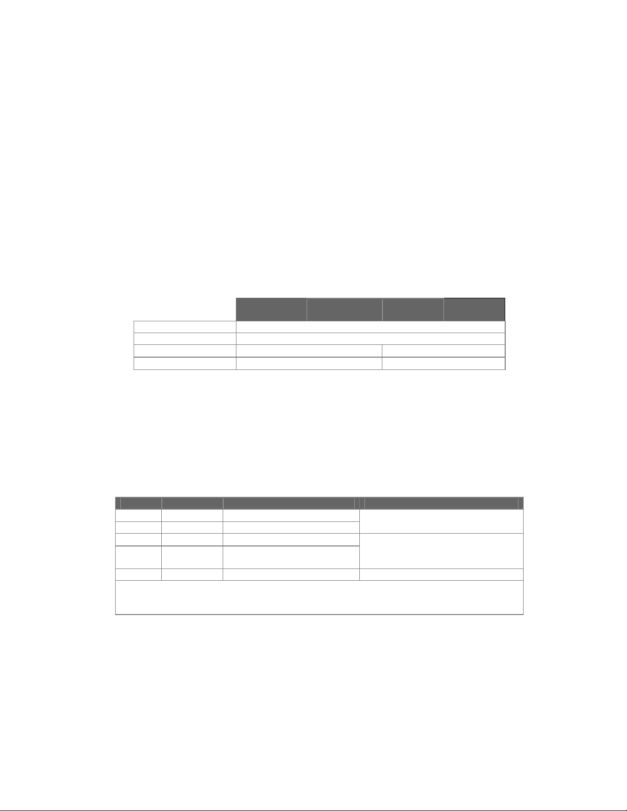
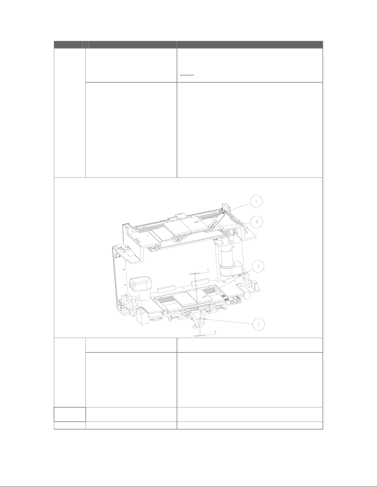
• Place the coupling flange (item 1,
Figure 1) on the X-Ray tube
housing (item 2, Figure 1) with
factory mounted alignment ring
(item 3, Figure 1)
• Positioning the reference pin (item
4, Figure 1) to the notch (item 5,
Figure 1) of the alignment ring.
Secure it with the four countersunk
•
screws M6 x 25 mm (item 6, Figure
1) and rings (item 7, Figure 1 )
• For screw length, see note above.
• Proceed with chapter 0 page 19.
CAUTION
Never loosen lacquered screws
(item 8, Figure 1. This will ruin the factory
alignment of the focus.
For realignment, the X-ray Source
assembly must be returned to Hamburg.
________________
Figure 1: Mounting the P&P coupling flange
(04.0) 17
9896 010
ALL RIGHTS RESERVED
2216.
2217.
2223.
2224.
Copyright © 2004 Philips Medical Systems Nederland B.V.
Page 14
Installation NICOL X-Ray Beam Limiting Device
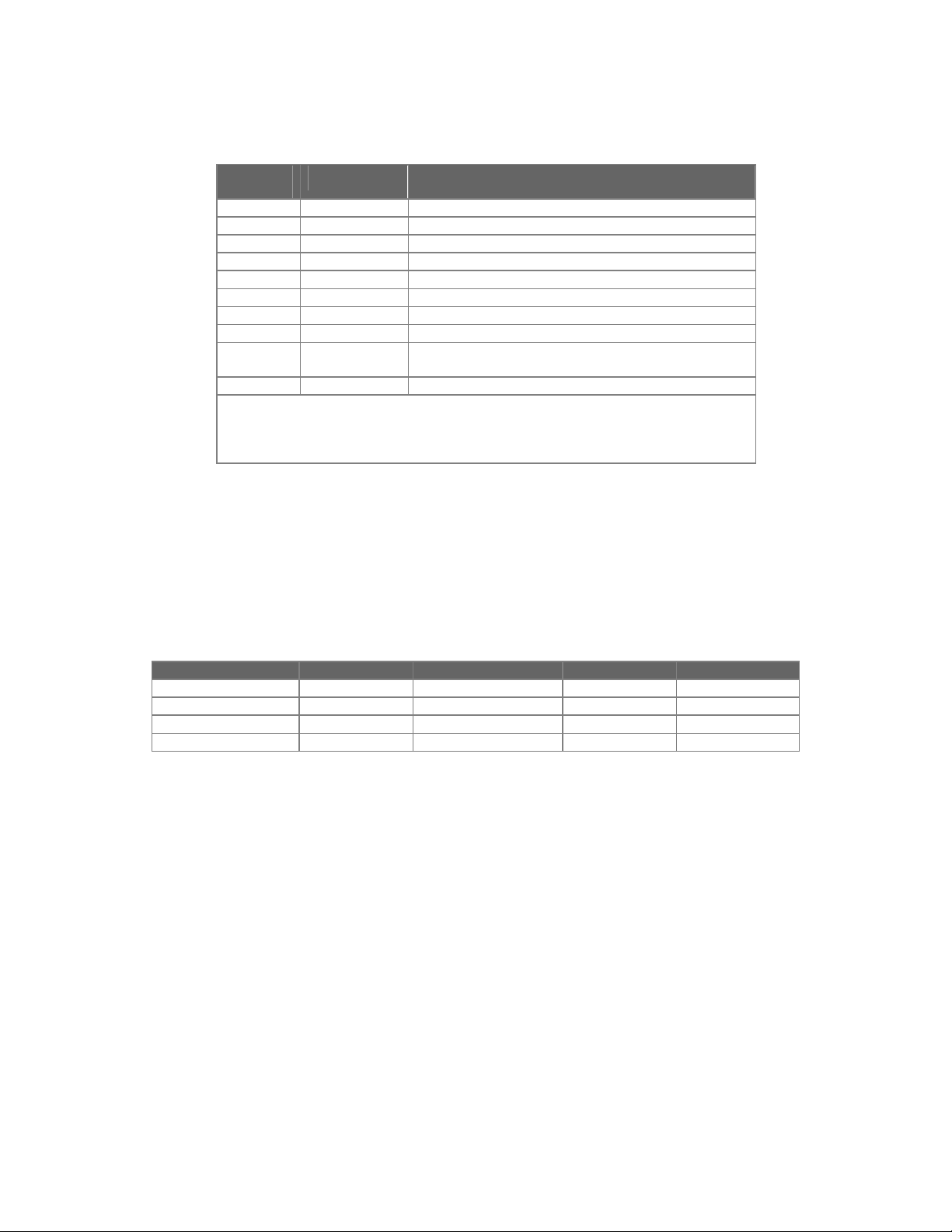
2.2.2 M
OUNTING THE COUPLING FLANGE ASSEMBLY
• Unscrew the locking plate screw (item 5, Figure 3, page 19) from each of the two locking plates
(item 1, Figure 3) and push them outwards as far as possible.
• Remove the shipping bracket (item 2, Figure 3) together with the coupling flange (item 3, Figure
3) from the BLD
• Unscrew the shipping bracket from the coupling flange (countersunk screws M6 x 25 mm must
be reused to mount the coupling flange on the tube housing.)
NOTE
Check the screw required length (25 mm) in the applicable tube housing service documentation.
At least 5 mm must be screwed into the tube housing.
________________
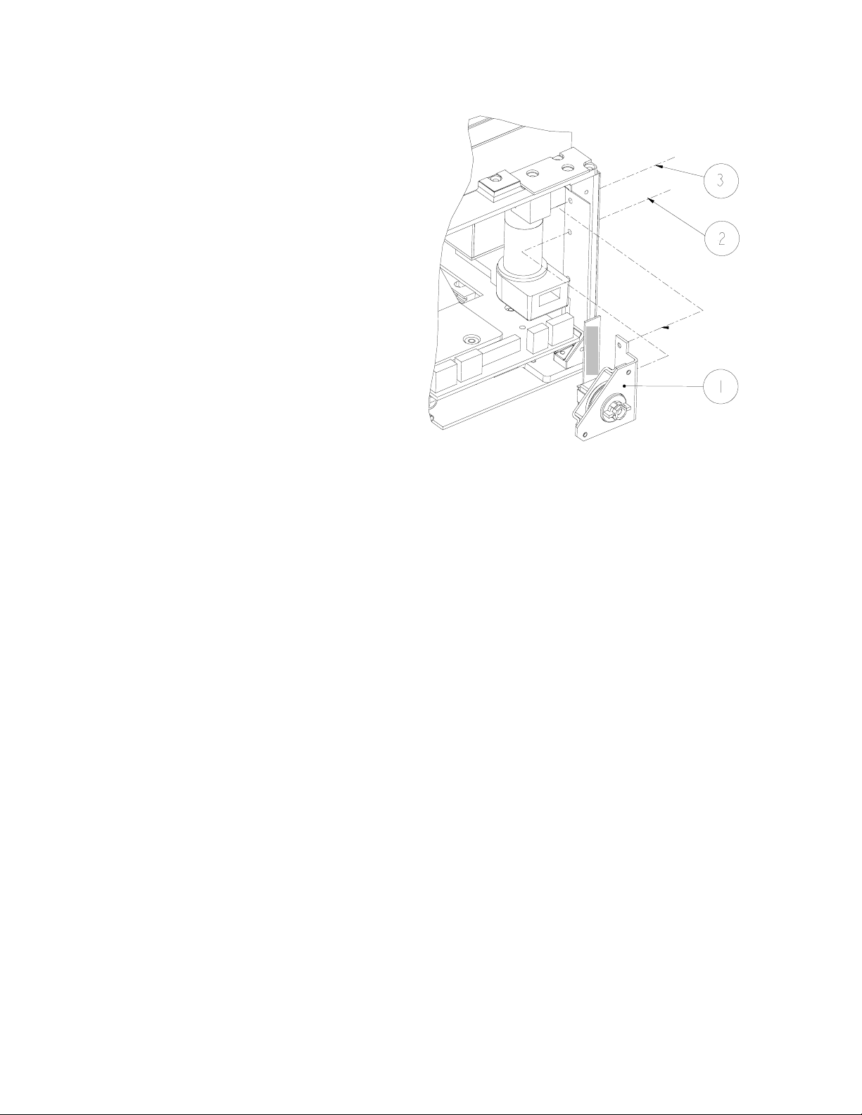
• Place the coupling flange (item 1, Figure 2) on the X-Ray tube housing (item 2, Figure 2),
positioning the 0° notch (item 5, Figure 2) to the rear of the X-Ray tube housing, and secure it
with the four countersunk screws M6 x 25 mm, item 3, Figure 2. (see note above)
Figure 2: Mounting the coupling flange assembly
2.2.3 CENTERING THE BLD WITH RESPECT TO THE X-RAY TUBE
All BLD functions have been accurately centered in the factory, relative to the central axis; any further
centering has to be done by adjusting the coupling flange assembly of the BLD with respect to the XRay focus. The specified alignment tool must be used.
The centering procedure is described in paragraph 6.1.4, page 40.
This procedure must be carried out:
• After replacement of NICOL DISC 4522 300 2417x
• After replacement of the X-Ray tube, configurations A and D of Table 3.
• NOT for replacements of NICOL and NICOL V2
18 (04.0)
ALL RIGHTS RESERVED
Copyright © 2004 Philips Medical Systems Nederland B.V.
9896 010
2216.
2217.
2223.
2224.
Page 15
NICOL X-Ray Beam Limiting Device Installation
2.2.4 M
Carefully mount the BLD to the coupling flange, in order not to DAMAGE the near focus shutters!
OUNTING THE
• Slide the two locking plates (item 1, Figure 3) outwards as far as possible.
• Mount the BLD on the coupling flange assembly, with the 0° locking mechanism (item 4, Figure
3) to slide into the notch (item 3) of the coupling flange
• Slide the two locking plates inwards to their end stop
• Secure the two locking plates to the coupling plate with the two screws (item 5)
• Check whether the BLD is properly secured
BLD
ON THE
AY TUBE HOUSING
X-R
NOTE
________________
Figure 3: Mounting the BLD to the coupling flange
NOTE
It is strongly advised, to mount the BLD on the X-Ray tube housing without removing the aesthetic
covers first. This allows a better grip of the heavy BLD, and prevents damage to the ruler, when lifting
the BLD by holding the ruler by accident.
________________
(04.0) 19
9896 010
ALL RIGHTS RESERVED
2216.
2217.
2223.
2224.
Copyright © 2004 Philips Medical Systems Nederland B.V.
Page 16

Installation NICOL X-Ray Beam Limiting Device
2.2.5 E
LECTRICAL INSTALLATION
• Mount the BLD first according
chapter 0, page 19.
Removal of Aesthetic Cover
• Remove the DSC knobs (item 1,
Figure 4), by pulling the knobs
outward.
• Remove the accessory rails
(item 2, Figure 4), by loosening
the 6 screws.
• Remove the 2 screws, (item 3,
Figure 4)
• Remove the two aesthetic
covers (items 4 and 5, Figure 4),
first lift item 4, and then lift item
5.
NOTE
When reassembling the Aesthetic covers,
be sure that the ruler guidance, item 6
Figure 4 page 20 is mounted correctly
between front and rear covers.
________________
Figure 4: Remove Aesthetic Cover
Removal of Ruler Side Plate
• In case of electronic ruler
(9896 010 2216.)
disconnect connector
LA5X1, item 4 Figure 5.
• Remove the side plate
(item 1, Figure 5) using the
4 screws (items 2).
Figure 5: Remove Ruler Side Plate
20 (04.0)
ALL RIGHTS RESERVED
Copyright © 2004 Philips Medical Systems Nederland B.V.
9896 010
2216.
2217.
2223.
2224.
Page 17

NICOL X-Ray Beam Limiting Device Installation
Electrical installation
• Connect male CAN cable 9p D-connector : LA2X1 (see Figure 6)
• Connect female CAN cable 9p D-connector : LA2X11
• Connect power cable 4p Mate-N-Lock : LA2X2
• Connect yellow/green protective earth : LAX100
Reinstall the ruler side plate
•
• For 9896 010 2216. only, reconnect ruler connector, LA5X1 and pay attention to proper ruler
cable guidance, see chapter 0 page 34, especially Figure 15 page 34.
• Switch on the Power and check whether
− LED LA3H1 (green) is ON
− LED’s LA3H2 (red) and are switched OFF within 30s (typical: approximately 15s).
− LED LA3H4 (yellow) is switched OFF (time is system dependant).
• Reinstall the two aesthetic covers, including the accessory rail and DSC knobs.
• Check whether the BLD is positioned correctly in the 0°-swivel position. When trying to swivel
the BLD with little force, no noticeable play may be present.
Figure 6: Electrical Installation
CAUTION
Be sure that during reinstallation of the aesthetic covers, the micro-switch for the lamp,
item 1, Figure 6, is not damaged!
________________
(04.0) 21
9896 010
ALL RIGHTS RESERVED
2216.
2217.
2223.
2224.
Copyright © 2004 Philips Medical Systems Nederland B.V.
Page 18

Installation NICOL X-Ray Beam Limiting Device
2.2.6 C
HECKING THE ALIGNMENT OF THE LIGHT FIELD AND THE
X-R
AY FIELD
1. Select large focus, 60 kV and 5 mAs
2. Place a loaded cassette (24 cm x 30 cm) on the
table top
(a)
(b)
cassette
washer (d)
3. Set SID = 100 cm (Use ruler)
4. Center the X-Ray tube on the cassette
5. Place a washer (d) on the right hand-top of the
cassette
6. Switch on the light and place four copper strips (c)
on the edge (a) of the Light Field
W1
L1
W2
L2
7. Make an exposure
8. Develop the film
9. Measure the differences L1, L2, W1 and W2
between the outer edge of each copper strips
image and the corresponding edge of the X-Ray
lightfield (a)
X-Ray Field (b)
(c)
Field (b).
10. The values L1 + L2 and W1 + W2 shall NOT
exceed 2cm (representing 2% of the SID)
Figure 7: Check X-Ray/Light Field
11. Note the measured values
12. Repeat preceding steps 1 till 11, with small focus selected.
The alignment procedure is described in paragraph 6.3, X-Ray Field to Light Field, page 45.
PTIONS
2.3 O
2.3.1 INSTALLATION AEP-METER
It is possible to install an optional AEP-meter in the accessory rail.
For the installation we refer to:
• relevant system reference manual for removal of the aesthetic cover and
• Service manual of the AEP-meter.
22 (04.0)
ALL RIGHTS RESERVED
Copyright © 2004 Philips Medical Systems Nederland B.V.
9896 010
2216.
2217.
2223.
2224.
Page 19

NICOL X-Ray Beam Limiting Device Fault Finding
3 FAULT FINDING
NOTE
NOT described in this document, is how to find to an FRU,
based on error messages, which are sent from the BLD to the system via the CAN.
This is described in the applicable system documentation, see the relevant system reference manual.
________________
NTRODUCTION
3.1 I
This chapter describes:
• indicators and measuring points for each PCB
• miscellaneous complaints and/or problems
Also for each problem, possible fault causes and/or solutions are given.
However to get feedback from the field as soon as possible, a very high FRU level is defined. So only
a very limited spare parts list is available.
In case of problems, the complete BLD has to be exchanged. The defect BLD, together with a clear
NOTE
problem description, has to be returned to Best as soon as possible!
________________
(04.0) 23
9896 010
ALL RIGHTS RESERVED
2216.
2217.
2223.
2224.
Copyright © 2004 Philips Medical Systems Nederland B.V.
Page 20

Fault Finding NICOL X-Ray Beam Limiting Device
AULTFIND STRATEGY
3.2 F
It is advised to start/perform faultfinding based on error messages as described in the relevant system
documentation, see system reference manual. Only if this is not possible, or does not lead to a
solution for the problem, this chapter may be of help. The faultfinding directly points to some basic
FRU’s (PCB’s and BLD) and a few FRU’s which are cheap and easy to replace.
3.3 INDICATORS
LED indicators are present on PCB’s LA2 and LA3.
The explanation of the LED indicators is given in Table 10 and Table 11. The location of the LED’s on
the PCB’s is given in Z3-2 to Z3-3.
3.3.1 LA2: P
Number Color Description Faultfinding and solutions
LA2H1 green +24V present In case H1 is OFF:
LA2H2 green +5V present In case H2 is OFF and H1 is ON:
LA2H3 green +5V CAN
LA2H4 green +12V lamp
OWER SUPPLY CONVERTER
Table 10: Indicators LA2
• check system power supply
• check cable connection from system to LA2X2
• replace LA2
• replace BLD
• check +24V (LA2MP1)
• remove LA3, when H2 is lit now, check voltage, and if
OK, replace LA3
• replace LA2
• replace BLD
• In case H3 is OFF:
present
present
Refer to Z3-2 for positions on the PCB
• check system CAN power supply
• check cable connection from system to LAX1 and
LAX11
• replace LA2
• replace BLD
In case H4 is OFF:
• check system power supply
• check cable connection from system to LA2X2
• replace LA2
• replace BLD
CAN
INTERFACE
(PSC_CAN)
24 (04.0)
ALL RIGHTS RESERVED
Copyright © 2004 Philips Medical Systems Nederland B.V.
9896 010
2216.
2217.
2223.
2224.
Page 21

NICOL X-Ray Beam Limiting Device Fault Finding
3.3.2 LA3: S
HUTTER IRIS FILTER LIGHT CONTROLLER
(SIFLCO)
Table 11: Indicators LA3
LA3H1
green
[5V]3
LA3H2
red
[PCB]
LA3H3
yellow
[CONHW]
LA3H4
yellow
[CAN]
Faultfinding and solutions
OFF OFF OFF OFF In case H1 to H4 are OFF:
• check power supply using LA2 indicators (and
applicable measuring points)
• replace LA2 (PSC_CAN)
• replace LA3
• replace BLD
ON ON
(blinking)
OFF ON PCB Power On Self Test running
Note: after switching on the power, the self-test is running
(LED’s blinking) for approximately 15 seconds.
ON OFF OFF OFF Application running
ON OFF *4 ON No CAN communication:
• check cable connection from system to LA2X1, LA2X11
• check system
• replace LA2 (PSC_CAN)
• replace LA3
• replace BLD
ON OFF ON * PCB connected HW defect:
(use error logging at system level to identify the function
and FRU that is malfunctioning)
• shutter/iris/filter ⇒ replace BLD
• temp sensor 1 ⇒ replace LA2 (PSC_CAN)
• temp sensor 2 ⇒ replace LA3 (SIFLCO)
• fan ⇒ replace fan
• lamp ⇒ check cable LA2X5/LA2X6
⇒ check LA2H4
⇒ check whether +12V is present
after power up within .... s
⇒ replace Lamp
ON ON OFF OFF PCB Power On Self Test failed
ON ON OFF ON
• replace LA3 (SIFLCO)
ON ON ON OFF
ON ON ON ON PCB Power On Self Test not started or failed
• no PROM, or PROM incorrectly placed
• wrong HW or SW version
• replace LA3 (SIFLCO)
Refer to Z3-3 for positions on the PCB
3
[text] represents corresponding text on PCB, close to LED
4
LED may be both ON or OFF (don’t care)
(04.0) 25
9896 010
ALL RIGHTS RESERVED
2216.
2217.
2223.
2224.
Copyright © 2004 Philips Medical Systems Nederland B.V.
Page 22

Fault Finding NICOL X-Ray Beam Limiting Device
3.3.3 M
EASURING POINTS
Table 12: Measuring Points
LA1: SYBA LA2: PSC_CAN LA3: SIFLCO LA5: RUCO
MP1 0V24 0V24 0V24
MP2 +24V +24V +24V
MP3 0V5 0V5 0V5
MP4 +5V +5V +5V
MP5 0V12
MP6 LIGHT_ON reserved
MP7 +12V
MP8 0VCAN
MP9 +12VCAN
Refer to Z3-1 to Z3-5 for the position on the PCB’s
3.3.4 MISCELLANEOUS
Table 13: Miscellaneous faultfinding
Function Fault Description Faultfinding & Solution
Light lamp can not be switched on via
switch LAS1
lamp can not be switched on via
CAN
check connection LA3X5
•
check lamp voltage
•
replace lamp
•
check micro-switch (Exchange micro-switch)
•
exchange BLD
•
• check for CAN connection if LA3H4 is ON (see
Table 11, page 8)
• check lamp voltage, LA2MP6 is 12V with respect
to LA2MP5
• replace lamp
Area defined by Light Field not
(completely) on film
• See 2.2.6 Checking the alignment of the light
field and the X-Ray field, page 22
• Size incorrect: See chapter 6.3.1 Light Field Size
Adjustment page 45
• Light Field shifted with respect to the X-Ray
Field: See chapter 6.3.3 Light Field Adjustment
After Replacing Lamp page 46
General
BLD does NOT function/start-up
Ruler (electronic) ruler values NOT
BLD does NOT function/start-up
after replacement DSC button
BLD no function at all
correct
• exchange BLD
check whether the correct DSC assembly is
•
mounted at the appropriate position
• exchange BLD
• replace ruler, see 4.9 Replace Electronic Ruler,
page 33
• Replace PCB, see 4.8 Replace LA3: SIFLCO
page 32
Swivel
0° position NOT stable (to much
• exchange BLD
play)
26 (04.0)
ALL RIGHTS RESERVED
Copyright © 2004 Philips Medical Systems Nederland B.V.
9896 010
2216.
2217.
2223.
2224.
Page 23
NICOL X-Ray Beam Limiting Device Fault Finding
Function Fault Description Faultfinding & Solution
Shutters
shutters do not close completely
(during start-up only)
• Backup shutters (item 3, Figure 8) or near focus
shutters (item 2) close before main shutters,
exchange BLD
Note:
During application shutters can NOT be fully closed.
shadow images on exposed film
• Coupling between main shutters (item 1, Figure
8) and near focus shutters (item 2) and/or backup
shutters (item 3) not correct, exchange BLD.
How to check?
1. Switch of power
2. Fully close main shutters (item 1) manually
3. Check near focus shutter opening (item 2)
4. 3 mm ≤ x ≤ 4.4 mm
5. Check backup shutters (item 3)
6. 2.4 mm ≤ y ≤ 3.8 mm
7. Repeat steps for shutters not visible in Figure
8
• Coupling between main shutters and followshutters (item 4) incorrect, exchange BLD.
Figure 8: Shutter identification and verification
DSC
Replaced DSC button does not
No movement shutters when
DSC knobs are rotated.
function
• Exchange DSC assembly.
• Exchange BLD.
• Check whether the correct DSC assembly is
mounted at the appropriate position, DSC-A
assembly at lamp side, DSC-B assembly at ruler
side.
• Check whether the DSC-A connector is correctly
mounted onto LA1X16.
• Check whether the DSC-B connector is correctly
mounted onto LA1X6.
Spectral
Filter
Filter not correctly positioned,
visible in images
• Replace LA3
• Exchange BLD
•
(04.0) 27
9896 010
ALL RIGHTS RESERVED
2216.
2217.
2223.
2224.
Copyright © 2004 Philips Medical Systems Nederland B.V.
Page 24

Replacements X-Ray Beam Limiting Device
4 REPLACEMENTS
ENERAL
4.1 G
•
• Never unplug connectors (LA1X7, LA1X12 and LA1X14) while power is switched on!
• Never touch lamp parts when lamp has been switched on for a long time, they may be very hot!
EPLACE (COMPLETE
4.2 R
For replacement of the complete BLD, see also chapter 2.2 Installation instructions, page 16
1. Place the BLD and X-Ray tube housing of the Stand (if possible) in the upright down position
2. Secure the Stand!
3. Open shutters as far as possible, using the DSC buttons.
4. Switch off the power!
5. Remove the Aesthetic Cover, see paragraph 2.2.5, page 20.
6. Remove the Ruler Side Plate, see paragraph 2.2.5
7. Remove the connectors, see paragraph 2.2.5
8. Replace BLD using procedure as described in paragraph 2.2.4
WARNING
Never put down the BLD on near focus shutter assembly.
Use external non-metal support(s) for the BLD.
________________
Switch off the power, when working with the BLD!
) BLD
Never lift the BLD, by holding the ruler, this to prevent damage to the ruler!
ON THE STAND
WARNING
________________
4.3 REPLACE AESTHETIC COVER
The Aesthetic Cover consists of three parts, which are always delivered together. They can be
replaced completely or as single parts.
1. For replacement front and/or rear cover see paragraph 2.2.5, page 20.
2. For replacement of the bottom plate see paragraph 4.14, page 38.
3. Assemble in reverse order.
4. Be sure that the ruler guidance item 6, Figure 4, page 20 is mounted correctly between the front
and rear cover.
5. Check BLD for correct functioning.
4.4 REPLACE FIELD INDICATION PLATE
1. Place the BLD and X-Ray tube housing of the Stand (if possible) in the upright down position
2. Remove the Aesthetic Cover, see paragraph 2.2.5, page 20.
3. Replace the field indication plate, item 7, Figure 4, page 20.
4. Assemble in reverse order.
28 (04.0)
ALL RIGHTS RESERVED
Copyright © 2004 Philips Medical Systems Nederland B.V.
9896 010
2216.
2217.
2223.
2224.
Page 25

NICOL X-Ray Beam Limiting Device Replacements
4.5 R
EPLACE
DSC B
UTTONS
1. Replace the DSC buttons, items 1, Figure 4, page 20, by pulling them outwards.
2. Assemble in reverse order.
4.6 REPLACE DSC ASSEMBLY
The DSC-A assembly is situated at the lamp
whereas the
side
DSC-B assembly
at the ruler side. (On the flat-cable of the DSC
assembly is indicated DSC-A respectively DSCB). It is not necessary to remove the BLD from
the X-Ray tube housing assembly for
replacement of the DSC assemblies.
CAUTION
When the lamp has been used, the lamp and its
surrounding material might be (“very”) hot.
________________
is situated
Figure 9: Removal iris motor assembly
Replace DSC-A assembly
1. Remove the Aesthetic Cover, see paragraph
2.2.5, page 20.
2. Be sure the power is switched OFF.
3. Remove the Lamp Side Plate, see paragraph
4.14, page 38.
4. Loosen the 2 screws, item 2 and 3, Figure 10,
page 29.
DSC-A
5. Remove DSC-A assembly, item 1, Figure 10,
page 29.
6. Remove iris motor assembly (only in case of
PEI 9896 010 2223.)
a) Disconnect connector LA1X10, item 3,
Figure 9, page 29 and LA1X11.
b) Loosen the 2 screws, both items 1, Figure
9.
c) Remove the iris motor assembly, item 2,
Figure 10: Replacement DSC-A assembly
7. Disconnect DSC connector LA1X16.
Figure 9.
8. Replace the DSC-A assembly and reassemble
(including iris motor) in reverse order.
9. Check proper functioning of the replaced DSC button after the power is switched ON
.
(04.0) 29
9896 010
ALL RIGHTS RESERVED
2216.
2217.
2223.
2224.
Copyright © 2004 Philips Medical Systems Nederland B.V.
Page 26
Replacements X-Ray Beam Limiting Device
Replace DSC-B assembly
1. Remove the Aesthetic Cover, see
paragraph 2.2.5, page 20.
2. Be sure the power is switched OFF.
3. Remove the Ruler Side Plate, see
paragraph 2.2.5
4. Disconnect DSC connector LA1X6.
5. Loosen the 2 screws, item 2 and 3, Figure
11, page 30.
6. Remove DSC-B assembly, item 1, Figure
11, page 30.
7. Replace the DSC-B assembly and
reassemble in reverse order.
8. Check proper functioning of the replaced
DSC button after the power is switched ON.
DSC-B
Figure 11: Replacement DSC-B assembly
WARNING
Be sure that the correct DSC assembly, see spare parts list, is mounted at the appropriate side of the
BLD. If interchanged, the BLD will not start up (so no CAN connection will be established) or the DSC
function will not become available.
________________
30 (04.0)
ALL RIGHTS RESERVED
Copyright © 2004 Philips Medical Systems Nederland B.V.
9896 010
2216.
2217.
2223.
2224.
Page 27

NICOL X-Ray Beam Limiting Device Replacements
EPLACE
4.7 R
LA2: PSC_CAN
1. Follow the instructions 1 - 7 of paragraph 4.2.
2. Remove the field indication plate, item 5, Figure 12
3. With Power still switched off, gently open rectangular shutters manually (Do NOT push shutters
downwards)
4. Remove connectors/fastons LA2X5 and LA2X6, see item 6, Figure 12.
5. Remove the 3 screws and washers (items 1, Figure 12).
6. A: Pop up the board LA2 (item 2) gently and
B: slide the board out of the BLD very carefully!
7. Re-assemble in reverse order. Be sure that the board connector (item 3) is positioned exactly in the
correct position onto the backpanel connector (item 4).
8. Check correct positioning of the connectors LA2X3 / LA1X1, observe via 2 holes in the long side of
the BLD (near item 4) and perpendicular to the connector via the short side of the BLD!
9. Check whether connectors/fastons LA2X5 and LA2X6, see item 6, Figure 12, are connected
correctly.
WARNING
Please check and double-check whether connector LA2X3 is correctly mounted to LA1X1!!!
________________
: Remove
B
A: Pop-up
Figure 12: Replace LA2 PSC_CAN
(04.0) 31
9896 010
ALL RIGHTS RESERVED
2216.
2217.
2223.
2224.
Copyright © 2004 Philips Medical Systems Nederland B.V.
Page 28

Replacements X-Ray Beam Limiting Device
EPLACE
4.8 R
LA3: SIFLCO
1. Follow the instructions 1 - 5 of paragraph 4.2.
2. Remove micro-switch connector LA3X5.
3. Remove the 4 sunken screws (items 2, Figure 13) from the LA3 Cover-plate (item 1, Figure 13) and
remove the LA3 Cover-plate
4. Remove 2 screws and washers (items 4) from LA3.
5. Remove the LA3, item 3, by lifting the board (connectors LA3X1 respectively LA3X2 from LA1X3
respectively LA3X4)
6. Exchange PROM LA3D17, see 4.8.1, page 32.
7. Reassemble in reverse order. Be sure that the board connectors (item 6) are positioned exactly in
the correct position onto the backpanel connectors (item 5).
8. Check correct positioning of the connectors LA3X1 respectively LA3X2 onto LA1X3 respectively
LA3X4
Figure 13: Replace LA3 SIFLCO
4.8.1 REPLACE PROM LA3D17
1. Follow steps 1-4 of paragraph 4.8
2. Remove PROM LA3D17 from socket, see Z3-3, by using an appropriate IC extractor
3. Place correct PROM into socket and check correct position, see Z3-3.
4. Reassemble in reverse order, steps 5-6 of paragraph 4.8
For safe handling of PCB’s and PROM’s we refer to ESD Precautions as described in Section 4:
Planned Maintenance Instruction Modules (4522 983 24611 or 4535 440 04161)
32 (04.0)
ALL RIGHTS RESERVED
Copyright © 2004 Philips Medical Systems Nederland B.V.
9896 010
2216.
2217.
2223.
2224.
Page 29

NICOL X-Ray Beam Limiting Device Replacements
EPLACE ELECTRONIC RULER
4.9 R
Figure 14: Replace Electronic Ruler
1. Secure the stand if necessary
2. Switch off the Power.
3. Remove the aesthetic cover, see paragraph 2.2.5, page 20.
4. Disconnect connector LA5X1 (item 4, Figure 14)
5. Remove the ruler Side-plate, see paragraph 2.2.5
6. Remove electrical ruler assembly (item 1, Figure 14) from the ruler Side-plate (item 3, Figure 14),
by loosening the three screws (item 2, Figure 14)
7. Mount new electrical ruler assembly and reconnect LA5X1.
8. Check whether the ruler can be pulled out smoothly.
9. Check whether the ruler winds up completely when released.
10. Reassemble in reverse order.
11. Switch on the power again.
12. Check whether the ruler value is correctly sent to the system via CAN. See applicable system
reference manual(s).
NOTE
With the aesthetic cover removed, the ruler can give incorrect values, so for the final check of the
ruler, the aesthetic cover has to be mounted!
________________
(04.0) 33
9896 010
ALL RIGHTS RESERVED
2216.
2217.
2223.
2224.
Copyright © 2004 Philips Medical Systems Nederland B.V.
Page 30

Replacements X-Ray Beam Limiting Device
4.9.1 C
ONNECTION ELECTRONIC RULER
Figure 15: Connect electrical ruler cable
Figure 15 page 34 gives in more detail, the connection of the cable of the electronic ruler. In case of
connection/disconnection of the electronic ruler cable, following steps have to be taken:
1. Remove ruler side plate, see chapter 2.2.5 page 20.
2. Remove connector LA1X5 (item 5 Figure 15) and cable (item 2 Figure 15). Cable must be
removed by pulling connector LA5X1 (item 1 Figure 15) through the hole (item 4 Figure 15) in
LA1.
3. Replace cable in reverse order
4. Mount ruler side plate, see chapter 2.2.5 page 20, while
5. Guiding ruler cable (item 3) together with power supply and CAN cable(s) through cable guidance.
34 (04.0)
ALL RIGHTS RESERVED
Copyright © 2004 Philips Medical Systems Nederland B.V.
9896 010
2216.
2217.
2223.
2224.
Page 31

NICOL X-Ray Beam Limiting Device Replacements
4.10 R
EPLACE MECHANICAL RULER
1. Remove the aesthetic cover, see paragraph 2.2.5, page 20.
2. Remove mechanical ruler assembly (item 1, Figure 16) from the ruler Side-plate (item 3, Figure
16), by loosening the three screws (item 2, Figure 16)
3. Mount new mechanical ruler assembly.
4. Check whether the ruler can be pulled out smoothly.
5. Check whether the ruler winds up when released.
Figure 16: Replace Mechanical Ruler
(04.0) 35
9896 010
ALL RIGHTS RESERVED
2216.
2217.
2223.
2224.
Copyright © 2004 Philips Medical Systems Nederland B.V.
Page 32

Replacements X-Ray Beam Limiting Device
4.11 R
EPLACE LAMP
CAUTION
Never touch the halogen lamp with
your fingers!
________________
1. Remove the aesthetic cover,
paragraph 2.2.5, page 20.
2. Remove Lamp Side Plate (item
1, Figure 17) by loosening the 4
screws (item 2, Figure 17)
3. Remove the protective cap of
the lamp, item 3, Figure 18, by
loosening the screw (item 4,
Figure 18)
4. Remove the lamp (item 1,
Figure 18) from the lamp-holder
(item 2)
5. Mount the new lamp in the
lamp-holder (Never touch with
your fingers)
6. Check whether the lamp pins
are placed in the lamp-foot as
far as possible!
Figure 17: Remove Lamp Side Plate
7. Check the alignment of the X-Ray Field with respect to the light Field, see chapter 2.2.6 page 22.
8. Reassemble in reverse order.
Attention!
Position
micro-switch
(item 8),
maximally
outwards!
Figure 18: Replacement Lamp
36 (04.0)
ALL RIGHTS RESERVED
Copyright © 2004 Philips Medical Systems Nederland B.V.
9896 010
2216.
2217.
2223.
2224.
Page 33

NICOL X-Ray Beam Limiting Device Replacements
4.12 R
EPLACE MICRO-SWITCH
1. Remove the aesthetic cover, paragraph 2.2.5, page 20.
2. Switch Power OFF.
3. Disconnect connector LAX5.
4. Remove the micro-switch (items 6 till 10, Figure 18 page 36).
5. Replace the micro-switch (item 8, Figure 18 page 36), reusing items 5, 6, 7, 9 and 10 and reconnect LAX5. Be sure the micro-switch is positioned maximally outwards before tightening the
screws.
6. Switch Power ON
7. Check proper functioning of the micro-switch.
8. Reassemble the aesthetic cover.
9. Check proper functioning of the micro-switch, with aesthetic cover reassembled.
WARNING
Maximum torque for tightening the screws items 6, Figure 18 page 36 = 11Ncm
________________
4.13 REPLACE MICRO-SWITCH INCLUDING BRACKET
1. Remove the aesthetic cover, paragraph 2.2.5, page 20.
2. Switch Power OFF.
3. Disconnect connector LAX5.
4. Remove the micro-switch including the bracket (items 5 till 10, Figure 18 page 36).
5. Replace the micro-switch including the bracket and re-connect LAX5. Be sure the micro-switch is
positioned maximally outwards before tightening the screws.
6. Switch Power ON
7. Check proper functioning of the micro-switch.
8. Reassemble the aesthetic cover.
9. Check proper functioning of the micro-switch, with aesthetic cover reassembled.
(04.0) 37
9896 010
ALL RIGHTS RESERVED
2216.
2217.
2223.
2224.
Copyright © 2004 Philips Medical Systems Nederland B.V.
Page 34

Replacements X-Ray Beam Limiting Device
4.14 R
EPLACE FAN
Figure 19: Replace Fan
1. Remove the BLD from the X-Ray tube assembly, see paragraph 4.2 and put BLD carefully in
upright down position.
2. Remove lamp side plate, item 3, Figure 19 using the four screws (item 4, Figure 19).
3. Remove bottom plate, item 1, Figure 19 , using the four screws, item 2 and washers item 8.
4. Remove ventilation shaft, item 5, Figure 19, from fan.
5. Disconnect fan connector LA1X17.
6. Remove fan, item 7, using the four screws, item 6, Figure 19).
7. Mount new fan
8. Reassemble the BLD in reverse order.
NOTE
Items 2 have to be fixed using Loctite 243 (screw lock)
________________
9. Check whether fan functions correctly, by switching on the lamp, using the light-button on the BLD.
38 (04.0)
ALL RIGHTS RESERVED
Copyright © 2004 Philips Medical Systems Nederland B.V.
9896 010
2216.
2217.
2223.
2224.
Page 35

NICOL X-Ray Beam Limiting Device Programming
5 PROGRAMMING
5.1 INTRODUCTION
This chapter describes the jumper settings for each board. The settings of other BLD programmable
functions, that must be changed with a software service tool are NOT described here, see relevant
Systems reference manual.
5.2 HARDWARE PROGRAMMING
5.2.1 LA1: B
Jumper Position Description Delivery Position
W1 1 - 2
5.2.2 LA2: P
ACKPANEL
2 - 3
OWER SUPPLY CONVERTER
Table 14: Programming LA1
BLD configured as frontal collimator (BLD1)
BLD configured as lateral collimator (BLD2)
Refer to Z3-1 for the position on the PCB
& CAN I
1 - 2
NTERFACE BOARD
(PSC_CAN)
Table 15: Programming LA2
Jumper Position Description Delivery Position
W1 1 - 2
none
W2
BLD programmed as CAN end node
BLD NOT an end node
Refer to Z3-2 for the position on the PCB
jumper NOT mounted
jumper
never
mounted!
5.3 SOFTWARE PROGRAMMING
All software programming is done at system level via the CAN interface. For this purpose, we refer to the
applicable system reference manual(s). Some examples of software programming at system level are:
• manual shutter speed
• shutter move limits (= radiation angle)
• BLD orientation (with respect to X-Ray tube housing)
• default Spectral Filter value
• spectral filter value assignment
• light timer settings
• default shutter position at reset
(04.0) 39
9896 010
ALL RIGHTS RESERVED
2216.
2217.
2223.
2224.
Copyright © 2004 Philips Medical Systems Nederland B.V.
Page 36

Adjustments NICOL X-Ray Beam Limiting Device
6 ADJUSTMENTS
This procedure only to be carried out:
• After replacement of NICOL DISC 4522 300 2417x
• After replacement of the X-Ray tube, configurations A and D of Table 3.
•
ENTERING THE
6.1 C
for replacements of NICOL and NICOL V2
NOT
BLD
WITH THE
X-R
AY TUBE
6.1.1 I
NTRODUCTION
For perfect attachment of the BLD to the X-Ray tube housing, it is necessary that the BLD axis coincides
with the median perpendicular line that passes through the center, between the two tube foci. Use BLD
alignment tool, see Figure 32, page 50. Ideally, the resulted picture consists of two concentric circles. In
reality there will be different pictures for small and large focus, see
Figure 22
, page 41.
6.1.2 TOOLS REQUIRED
The BLD alignment tool, code number 4522 980 31521
6.1.3 M
OUNTING THE
BLD A
The BLD alignment tool can be mounted:
• if the coupling flange assembly is not mounted, first perform this procedure as described in
paragraph 2.2.2, page 18.
• if the coupling flange assembly is mounted, similar procedure as for BLD mounting, see
paragraph 0, page 19.
6.1.4 C
HECKING THE CENTERING FOR
To check the BLD centering relative to the X-Ray tube, proceed as follows:
1. Prepare a film cassette (with screen) oriented in the plane perpendicular to the central ray, with the
edges of the film parallel to the longitudinal axis of the tube.
2. Set the following data: 65kV, 30mAs, SID=100mm (or more)
3. Make an exposure with small focus (SF)
Develop the film and determine:
• the center MA of the projection of ring A (see Figure 20)
• the center MB of the projection of ring B (see Figure 20)
• Draw the system coordinates on the film in the A-direction and B-
direction with reference to the film edges. (the positive directions
can be derived from the mark at the right-hand top of the film)
4. Measure the distances P and Q on the film
5. Make an exposure with
Develop the film and determine:
• the center MA of the projection of ring A (see Figure 21)
LIGNMENT TOOL
Mark the right hand top of the film!
focus (LF)
large
PEI 9896 010 2216.
NOTE
________________
B-direct ion
-a +a
A-direct ion
small focus
+b
P
MB
MA
-b
Q
mark
Figure 20: SF alignment
40 (04.0)
ALL RIGHTS RESERVED
Copyright © 2004 Philips Medical Systems Nederland B.V.
9896 010
2216.
2217.
2223.
2224.
Page 37

NICOL X-Ray Beam Limiting Device Adjustments
the center MB of the projection of ring B (see Figure 21)
•
• Draw the system coordinates on the film in the A-direction and B-
direction with reference to the film edges. (the positive directions
can be derived from the mark at the right-hand top of the film)
6. Measure the distances R and S on the film
7. The coupling flange is correctly adjusted when the film image of the
small focus is a mirror image with respect to that of the large focus (see
Figure 22) In this case the following applies:
B-direct ion
-a +a
S
large focus
+b
R
MA
MB
mark
|P| = |-R| ± 0.3mm
|Q| = |-S| ± 0.3mm
8. Further correction is not recommended because the adjustment can
become worse due to measuring errors during the correction
A-direct ion
-b
procedure.
Figure 21: LF alignment
If the above tolerances have
B-direction
been fulfilled, remove the BLD
small focus
+b
mark
large focus
+b
mark
alignment tool and proceed to
BLD mounting as described in
paragraph 0, page 19. If not,
proceed to paragraph 6.1.5.
-a +a
MA
P
MB
Q
-a +a
R
MA
S
MB
P = - R
A-direction
-b
Q = - S
-b
Figure 22: Requirement for alignment
6.1.5 ADJUSTING THE CENTRING
To adjust the BLD centering with the X-Ray tube, proceed as follows:
1. Measure the distances A, B, C and D (see Figure 23) and enter them as default values in Table 17
below.
2. Determine: Ta = (P + R)/2
Ub = (Q + S)/2
Va = Ta x Z
Wb = Ub x Z
with the factor Z derived from the following table, depending on the selected SID:
Table 16: Z-factor
SID [mm] 1250 1100 1000 900 800 700
Z 0.40 0.46 0.50 0.55 0.62 0.70
(04.0) 41
9896 010
ALL RIGHTS RESERVED
2216.
2217.
2223.
2224.
Copyright © 2004 Philips Medical Systems Nederland B.V.
Page 38

Adjustments NICOL X-Ray Beam Limiting Device
3. Calculate the corrected value of A, B, C and D as follows:
Corrected A = default A + Va
Corrected B = default B + Wb
Corrected C = default C - Wb
Corrected D = default D - Va
And enter them as corrected values in Table 17 below.
4. Loosen the four coupling flange assembly countersunk
screws a quarter turn.
5. Rotate the adjusting screws (Items W) to obtain the
corrected values of distances A, B, C and D.
6. Tighten the four countersunk screws, taking care that the
adjustment does NOT change.
7. Refer to paragraph 6.1.4 to check the centering.
Table 17: Centering correction values
Default values Corrected values
A
B
C
D
Example:
The following values Va = + 0.5mm and Wb = -1mm are the result of measurements and calculations.
Figure 23: Adjusting the centering
A
-a
W
C
W
+b
D
-b
B
+a
Table 18: Centering correction values (example)
Default values Corrected values
A 2.5mm 3(+0.5)mm
B 3.0mm 2(-1.0)mm
C 2.5mm 2(-0.5)mm
D 3.0mm 4(+1.0)mm
42 (04.0)
ALL RIGHTS RESERVED
Copyright © 2004 Philips Medical Systems Nederland B.V.
9896 010
2216.
2217.
2223.
2224.
Page 39

NICOL X-Ray Beam Limiting Device Adjustments
6.1.6 CHECKING THE CENTERING FOR PEI’S 9896 010 2217., 9896 010 2223. AND 9896
010 2224.
To check the BLD centering relative to the X-Ray tube, proceed as follows:
1. For details see relevant system reference manual(s)
2. Start fluoroscopy with
grey outer circle, observed on monitor.
3. If not, stop fluoroscopy and loosen the four coupling flange assembly countersunk screws, see
Figure 23, page 42, a quarter turn.
4. Rotate the adjusting screws (Items W, Figure 23, page 42) in such a way, that the white circle
becomes concentric with respect to the grey outer circle, observed on monitor.
Take care of necessary X-Ray precautions!
5. Tighten the four countersunk screws, taking care that the adjustment does NOT change.
6. Check whether the alignment does not change too much, when switching to large focus. (For
requirements see relevant system reference manual)
focus selected and check whether the white circle is concentric with the
small
Figure 24: SF alignment during Fluoroscopy
(04.0) 43
9896 010
ALL RIGHTS RESERVED
2216.
2217.
2223.
2224.
Copyright © 2004 Philips Medical Systems Nederland B.V.
Page 40

Adjustments NICOL X-Ray Beam Limiting Device
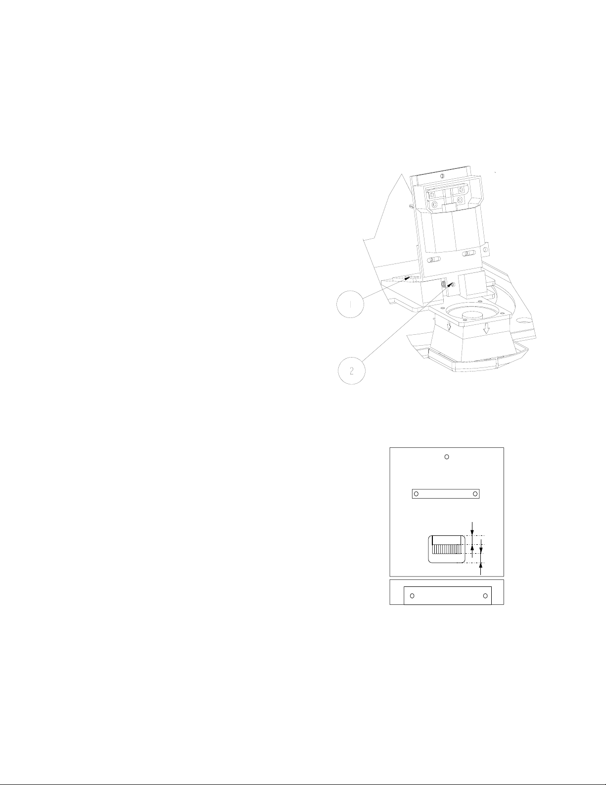
6.2 FIELD INDICATION PLATE WITH CROSSED-LINES
Preconditions for the Field Indication Plate adjustment:
• The X–ray field and light field should be correctly aligned.
• The output window of the BLD must be parallel to the receptor plane.
• The SID should be as large as possible (100 cm or more).
• Check whether the field indication plate is mounted correctly onto the adjusting strip, item 2
Figure 25
Procedure (refer to Figure 25, Page 44)
1. Close the vertical shutters (shutters A) manually, by using the corresponding DSC-button, to an
opening at receptor or table, of approximately 30 mm. (lamp automatically switches on)
2. Open the horizontal shutters (shutters B) completely (use corresponding DSC-button).
3. Loosen the two screws (items 3, Figure 25) and move the adjusting strip (item 2) and the Field
Indication Plate (item 1, Figure 25) so that the center of the Field Indication Plate cross-lines is
parallel and within 2.5 mm of the light field center line.
4. Close the horizontal shutters to an opening at receptor or table of approximately 30 mm.
5. Open the vertical shutters (shutters A) completely.
6. Move the adjusting strip (item 2, Figure 25) and Field Indication Plate (item 1, Figure 25) so that the
center of the cross of the Field Indication Plate is parallel and within 2.5 mm of the centerline of the
light field.
7. Secure the adjusting strip with the two screws (items 3, Figure 25).
Figure 25: Adjustment Field Indication Plate
44 (04.0)
ALL RIGHTS RESERVED
Copyright © 2004 Philips Medical Systems Nederland B.V.
9896 010
2216.
2217.
2223.
2224.
Page 41
NICOL X-Ray Beam Limiting Device Adjustments
6.3 X-RAY FIELD TO LIGHT FIELD
6.3.1 LIGHT FIELD SIZE ADJUSTMENT
This procedure must be carried out:
• if the check of the alignment of the X-Ray Field to the Light Field (chapter 2.2.6, page 22) failed
For adjustment of the size of the Light Field with respect to
the X-Ray Field, the following procedure has to be used.
1. Remove aesthetic covers, see chapter 2.2.5, page 20.
2. Remove lamp side plate, see chapter 2.2.5, page 20.
3. Loosen the 2 screws, item 1, Figure 26.
4. IF Light Field > X-Ray Field THEN turn screw, item 2,
Figure 26, clockwise to reduce the Light Field.
5. IF Light Field < X-Ray Field THEN turn screw, item 2,
Figure 26 counter clockwise to enlarge the Light Field.
6. After completing the adjustment, tighten the 2 screws,
item 1, Figure 26.
7. The adjustment must be checked according the
procedure as described in chapter 2.2.6, page 22
6.3.2 LAMP ADJUSTMENT AFTER REPLACING
Figure 26: X-Ray Field/Light Field alignment
LAMP
This procedure only has to be carried out:
• If after replacement of the lamp, the Check the
alignment of the X-Ray Field to the Light Field (chapter
2.2.6, page 22) failed because the Light Field with
respect to the X-Ray Field is shifted in x direction.
(Definition see Figure 29, page 46)
The following procedure is to be used:
1. After replacing the lamp, the alignment of the X-Ray Field with
respect to the Light Field must be checked according the
procedure as described in chapter 2.2.6, page 22
2. If not OK proceed with the following steps.
3. Remove the Field Indication Plate, item 1, Figure 25, page 44
4. Place a film (density 3) or paper on the BLD output screen.
5. Switch on the lamp
6. Look perpendicular onto the mirror and check visually, that the
filaments of the lamp are correctly positioned (A = B), see Figure
27 page 45.
7. If not OK, reposition lamp (Don’t touch lamp with your fingers,
also lamp is getting very hot!)
Figure 27: Lamp Adjustment
8. Finally, the alignment of the X-Ray Field with respect to the Light
Field must be checked again according the procedure as described in chapter 2.2.6, page 22. If not
correct, repeat procedure as described in chapter 2.2.6, page 22, starting from step 6.
A
B
(04.0) 45
9896 010
ALL RIGHTS RESERVED
2216.
2217.
2223.
2224.
Copyright © 2004 Philips Medical Systems Nederland B.V.
Page 42

Adjustments NICOL X-Ray Beam Limiting Device
6.3.3 LIGHT FIELD ADJUSTMENT AFTER REPLACING LAMP
This procedure only has to be carried out:
• If after replacement of the lamp, the Check the alignment of the X-Ray Field to the Light Field
(chapter 2.2.6, page 22) failed because the Light Field with respect to the X-Ray Field is shifted
in y direction. (Definition see Figure 29, page 46)
Swap Lamp:
1. Allow the lamp to cool down
2. Remove the lamp, do NOT touch the lamp with your fingers.
3. Reinstall the lamp, with the lamp pins switched
4. Perform Lamp Adjustment After Replacing Lamp chapter
6.3.2 page 45 .
5. Check the alignment of the X-Ray Field to the Light Field
(chapter 2.2.6, page 22)
Figure 28: Swap Lamp pins
Figure 29: Definition x and y direction
46 (04.0)
ALL RIGHTS RESERVED
Copyright © 2004 Philips Medical Systems Nederland B.V.
9896 010
2216.
2217.
2223.
2224.
Page 43

NICOL X-Ray Beam Limiting Device Adjustments
6.4 ELECTRICAL ADJUSTMENT
There are NO electrical adjustments required for the BLD.
6.5 SOFTWARE ADJUSTMENTS
All software adjustments with respect to the BLD are described in the relevant system reference manual.
The BLD has NO direct service entry; this is provided by the system and described in the system
reference manual. The following software adjustments with respect to the BLD are applicable:
• Focus-depth correction
• II-format adjustment
(04.0) 47
9896 010
ALL RIGHTS RESERVED
2216.
2217.
2223.
2224.
Copyright © 2004 Philips Medical Systems Nederland B.V.
Page 44

NICOL X-Ray Beam Limiting Device
7 LIST OF FIGURES AND DRAWINGS
FIGURE 1: MOUNTING THE P&P COUPLING FLANGE 17
FIGURE 2: MOUNTING THE COUPLING FLANGE ASSEMBLY 18
FIGURE 3: MOUNTING THE BLD TO THE COUPLING FLANGE 19
FIGURE 4: REMOVE AESTHETIC COVER 20
FIGURE 5: REMOVE RULER SIDE PLATE 20
FIGURE 6: ELECTRICAL INSTALLATION 21
FIGURE 7: CHECK X-RAY/LIGHT FIELD 22
FIGURE 8: SHUTTER IDENTIFICATION AND VERIFICATION 27
FIGURE 9: REMOVAL IRIS MOTOR ASSEMBLY 29
FIGURE 10: REPLACEMENT DSC-A ASSEMBLY 29
FIGURE 11: REPLACEMENT DSC-B ASSEMBLY 30
FIGURE 12: REPLACE LA2 PSC_CAN 31
FIGURE 13: REPLACE LA3 SIFLCO 32
FIGURE 14: REPLACE ELECTRONIC RULER 33
FIGURE 15: CONNECT ELECTRICAL RULER CABLE 34
FIGURE 16: REPLACE MECHANICAL RULER 35
FIGURE 17: REMOVE LAMP SIDE PLATE 36
FIGURE 18: REPLACEMENT LAMP 36
FIGURE 19: REPLACE FAN 38
FIGURE 20: SF ALIGNMENT 40
FIGURE 21: LF ALIGNMENT 41
FIGURE 22: REQUIREMENT FOR ALIGNMENT 41
FIGURE 23: ADJUSTING THE CENTERING 42
FIGURE 24: SF ALIGNMENT DURING FLUOROSCOPY 43
FIGURE 25: ADJUSTMENT FIELD INDICATION PLATE 44
FIGURE 26: X-RAY FIELD/LIGHT FIELD ALIGNMENT 45
FIGURE 27: LAMP ADJUSTMENT 45
FIGURE 28: SWAP LAMP PINS 46
FIGURE 29: DEFINITION X AND Y DIRECTION 46
FIGURE 30: ITEMS SUPPLIED 49
FIGURE 31: EQUIPMENT IDENTIFICATION 49
FIGURE 32: ALIGNMENT TOOL 50
TABLE 1: VERSION SURVEY 8
TABLE 2: NICOL CONFIGURATIONS 9
TABLE 3: COMPATIBILITY OVERVIEW 9
TABLE 4: DIMENSIONS AND WEIGHT 10
TABLE 5: POWER SUPPLY INTERFACE 10
TABLE 6: CAN INTERFACE 11
TABLE 7: SW OVERVIEW 11
TABLE 8: FILTER MATERIAL/POSITION ASSIGNMENT 12
TABLE 9 INSTALLATION SEQUENCE 16
TABLE 10: INDICATORS LA2 24
TABLE 11: INDICATORS LA3 25
TABLE 12: MEASURING POINTS 26
TABLE 13: MISCELLANEOUS FAULTFINDING 26
TABLE 14: PROGRAMMING LA1 39
TABLE 15: PROGRAMMING LA2 39
TABLE 16: Z-FACTOR 41
TABLE 17: CENTERING CORRECTION VALUES 42
TABLE 18: CENTERING CORRECTION VALUES (EXAMPLE) 42
48 (04.0)
ALL RIGHTS RESERVED
Copyright © 2004 Philips Medical Systems Nederland B.V.
9896 010
2216.
2217.
2223.
2224.
Page 45
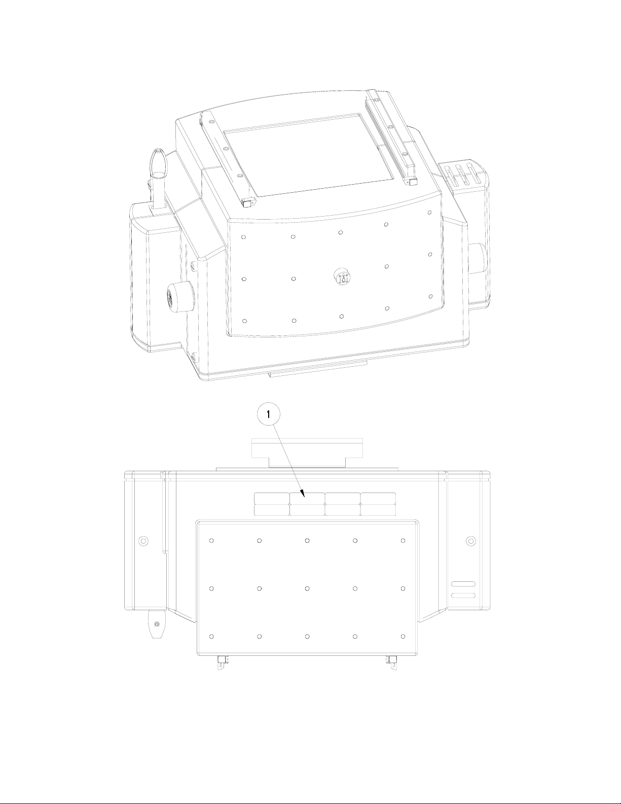
NICOL X-Ray Beam Limiting Device
Figure 30: ITEMS SUPPLIED
Figure 31: EQUIPMENT IDENTIFICATION
(04.0) 49
9896 010
ALL RIGHTS RESERVED
2216.
2217.
2223.
2224.
Copyright © 2004 Philips Medical Systems Nederland B.V.
Page 46
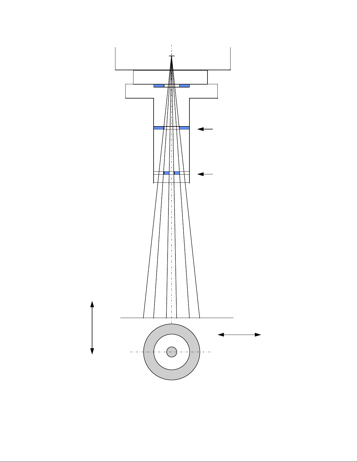
NICOL X-Ray Beam Limiting Device
focus
A
B
B direction (transversal)
A direction (longitudinal)
Figure 32: Alignment Tool
50 (04.0)
ALL RIGHTS RESERVED
Copyright © 2004 Philips Medical Systems Nederland B.V.
9896 010
2216.
2217.
2223.
2224.
Page 47

NICOL X-Ray Beam Limiting Device
P. PARTS LIST
For parts list refer to the following internet page:
http://dehsspf1.de.ms.philips.com\pms\index.html
and refer to the program Spare Parts Finder (CD-ROM)
(04.0) 51
9896 010
ALL RIGHTS RESERVED
2216.
2217.
2223.
2224.
Copyright © 2004 Philips Medical Systems Nederland B.V.
Page 48

NICOL X-Ray Beam Limiting Device
Z. DRAWINGS
Z1-1 SIMPLIFIED DIAGRAM POWER SUPPLIES
Z1-2 SIMPLIFIED DIAGRAM X-RAY BEAM LIMITING DEVICE
Z2-1 WIRING X-RAY BEAM LIMITING DEVICE
Z3-1 LA1 - SYSTEM BACKPANEL
Z3-2 LA2 - PSC-CAN
Z3-3 LA3 - SIFLCO
Z3-5 LA5 - RUCO
52 (04.0)
ALL RIGHTS RESERVED
Copyright © 2004 Philips Medical Systems Nederland B.V.
9896 010
2216.
2217.
2223.
2224.
 Loading...