

INTEGRATED CIRCUITS
74F552
Octal registered transceiver with parity
and flags (3-State)
Product specification
IC15 Data Handbook
1991 Jan 02
Philips Semiconductors Product specification
74F552Octal registered transceiver with parity and flags (3-State)
FEA TURES
•8-bit bidirectional I/O port with handshake
•Register status flag flip-flops
•Separate clock enable and output enable
•Parity generation and parity check
•B outputs and parity output sink 64mA
DESCRIPTION
The 74F522 Octal Registered Transceiver contains two 8-bit
registers for temporary storage of data flowing in either direction.
Each register has its own clock (CPR, CPS) and Clock Enable
(CER
, CES) inputs, as well as a flag flip-flop that is set automatically
as the register is loaded. The flag output will be reset when the
Output Enable returns to High after reading the output port. Each
register has a separate Output Enable (OEAS
buffer . The separate Clocks, Flags and Enables provide
considerable flexibility as I/O ports for demand-response data
transfer. When data is transferred from the A port to the B port, a
parity bit is generated. On the other hand, when data is transferred
from the B port to the A port, the parity of input data on B0–B7 is
checked.
TYPE
TYPICAL f
MAX
74F552 85MHz 120mA
ORDERING INFORMATION
COMMERCIAL RANGE
DESCRIPTION
28-Pin Plastic DIP
VCC = 5V ±10%,
T
= 0°C to +70°C
amb
N74F552N SOT117-2
(600mil)
28-Pin Plastic SOL N74F552D SOT136-1
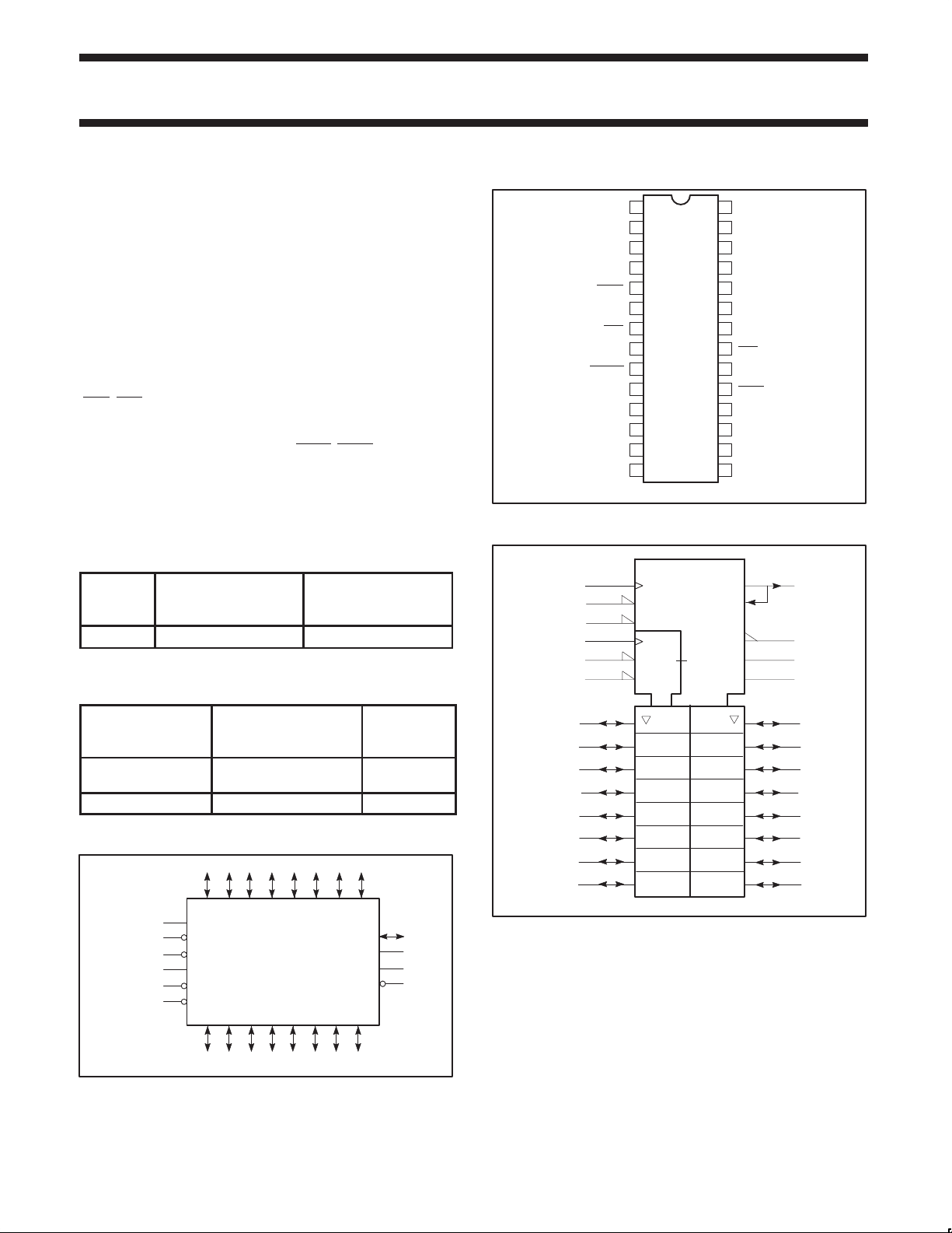
LOGIC SYMBOL
18 17 16 15 14 13 12
, OEBR) for its 3-State
TYPICAL SUPPL Y
CURRENT
(TOTAL)
PKG DWG #
11
PIN CONFIGURATION
1
B4
2
B5
3
B6
4
B7
5
OEBR
6
CPR
7
CER
8
V
CC
9
ERROR
10
FS
11
A7
12 17
A6
13 16
A5
14 15
A4
LOGIC SYMBOL (IEEE/IEC)
6
7
5
20
21
19
18
17
16
15
14
13
12
11
XCVR
1C2
EN1’
EN6
6C4
EN3
EN6
3,4,6
Z7
28
27
26
25
24
23
22
21
20
19
18
SF01039
5,6
5,6
6,7
1,2,6
B3
B2
B1
B0
FR
PARITY
GND
CES
CPS
OEAS
A0
A1
A2
A3
6
5
23
9
10
14
25
26
27
28
1
2
3
4
A0 A1 A4 A5 A6 A7
CPR
CER
CES
CPS
OEAS
OEBR
B0 B1 B4 B5 B6 B7
= Pin 8
V
CC
GND = Pin 22
6
7
21
20
19
5
1991 Jan 02 853–1098 01347
A3A2
B2 B3
26 27 28
SF01040
FS
FR
23
10
24
9
SF01041
PARITY
ERROR
123425
2

Philips Semiconductors Product specification
PARITY
74F552Octal registered transceiver with parity and flags (3-State)
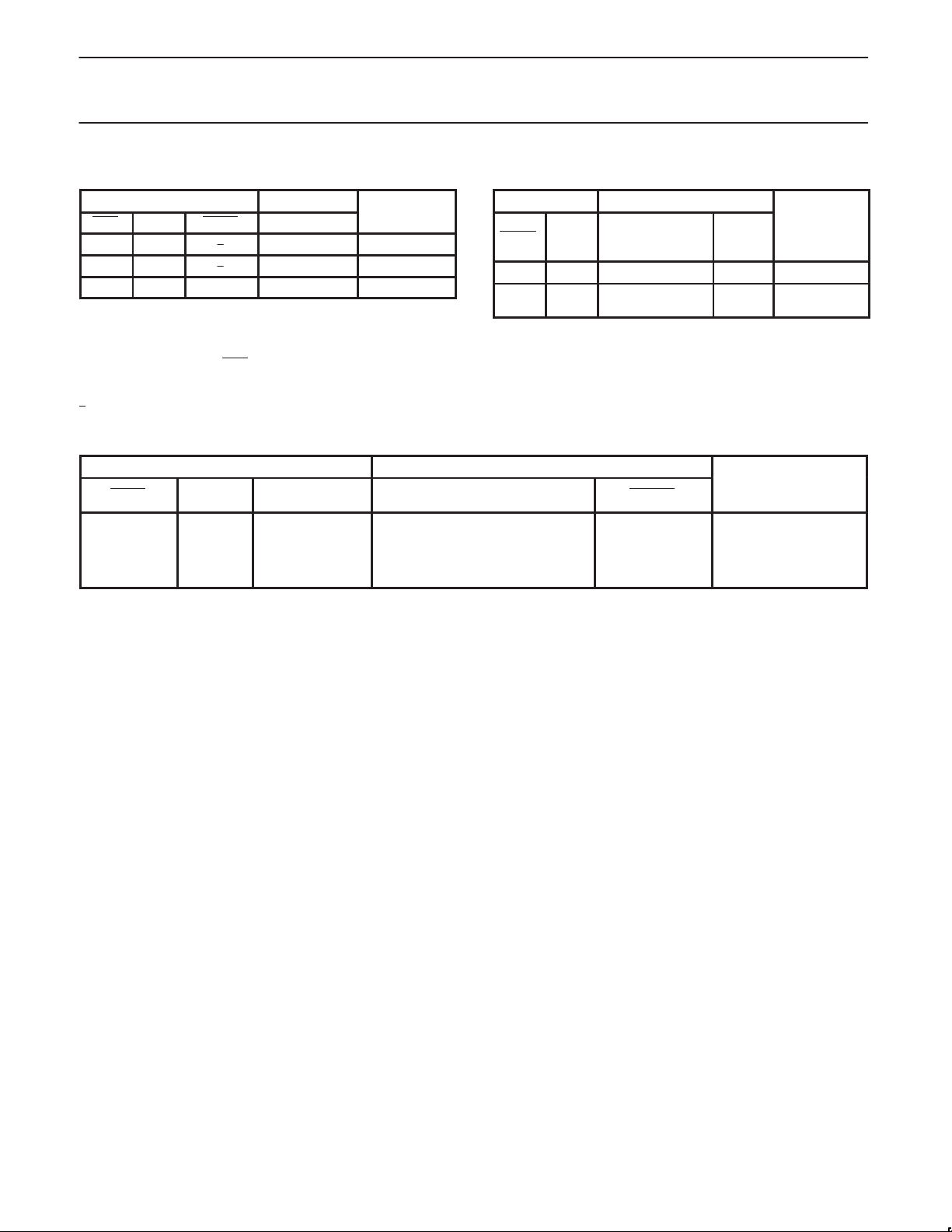
INPUT AND OUTPUT LOADING AND FAN-OUT TABLE
PINS DESCRIPTION
A0–A7 A Data inputs 3.5/1.0 70µA/0.6mA
B0–B7 B Data inputs 3.5/1.0 70µA/0.6mA
CPR R registers clock input (active rising edge) 1.0/1.0 20µA/0.6mA
CPS S registers clock input (active rising edge) 1.0/1.0 20 µA/0.6mA
CER R registers clock Enable input (active Low) 1.0/1.0 20µA/0.6mA
CES S registers clock Enable input (active Low) 1.0/1.0 20µA/0.6mA
OEBR
OEAS
ERROR Parity check output (active Low) 50/33.3 1.0mA/20mA
A0–A7 A Data outputs 150/40 3.0mA/24mA
B0–B7 B Data outputs 750/106.7 15mA/64mA
FR A-to-B Status Flag output (active High) 50/33.3 1.0mA/20mA
FS B-to-A Status Flag output (active High) 50/33.3 1.0mA/20mA
NOTE: One (1.0) FAST Unit Load is defined as: 20µA in the High state and 0.6mA in the Low state.
A-to-B Output Enable input (active Low)
and clear FS output (active Low)
B-to-A Output Enable input (active Low)
and clear FR output (active Low)
Parity bit transceiver input 3.5/1.0 70µA/0.6mA
Parity bit transceiver output 750/106.7 15mA/64mA
74F(U.L.)
HIGH/LOW
1.0/2.0 20µA/1.2mA
1.0/2.0 20µA/1.2mA
LOAD VALUE
HIGH/LOW
FUNCTIONAL DESCRIPTION
Data applied to the A inputs are entered and stored on the rising
edge of the CPR clock pulse, provided that the CER
simultaneously, the status flip-flop is set and the A-to-B flag (FR)
output goes High. As the CER
in R register. This data entered from the A inputs will appear at the B
port I/O pins after the OEBR has gone Low. When OEBR is Low, a
parity bit appears at the PARITY pin, which will be set High when
there is an even number of 1s or all 0s at the Q outputs of the R
register. After the data is assimilated, the receiving system clears
the flag FR, by changing the signal at the OEBR
High. Data flow from B-to-A proceeds in the same manner described
for A-to-B flow. A Low at the CES
the CPS pin enters the B input data and the parity input data into the
S register and the parity register respectively and set the flag output
FS to High. A Low signal at the OEAS
pins and a Low-to-High transition of the OEAS
flag. When OEAS
High if there is an odd number of 1s at the Q outputs of the S
register and the parity register.
is Low, the parity check output ERROR will be
returns to High, the data will be held
pin and a Low-to-High transition at
pin enables the A port I/O
is Low;
pin from Low to
signal clears the FS
R or S REGISTER FUNCTION TABLE
INPUTS OUTPUTS
An or Bn CPX CEX INTERNAL Q
X X H NC Hold data
L
H
X ↑ L NC Keep old data
H = High voltage level
L = Low voltage level
NC= No change
X = Don’t care
X = R or S for CPX and CEX
↑ = Low-to-High transition
↑
= Not Low-to-High transition
↑
↑
L
L
L
H
OPERATING
OUTPUT CONTROL TABLE
INPUT OUTPUTS
OEXX INTERNAL Q An or Bn
H X Z Disable outputs
L
L
H = High voltage level
L = Low voltage level
X = Don’t care
XX= AS or BR
Z = High impedance “off” state
L
H
L
H
OPERATING
Enable outpus
MODE
Load data
MODE
1991 Jan 02
3
Philips Semiconductors Product specification
74F552Octal registered transceiver with parity and flags (3-State)
R or S FLAG FUNCTION TABLE
INPUTS OUTPUTS
CEX CPX OEXX FR or FS
H X ↑ NC Hold flag
L ↑ ↑ H Set flag
X X ↑ L Clear flag
H = High voltage level
L = Low voltage level
NC= No change
X = Don’t care
X = R or S for CPX and CEX
XX= AS or BR
↑ = Low-to-High transition
↑
= Not Low-to-High transition
OPERATING
PARITY CHECK FUNCTION TABLE
INPUTS OUTPUTS
OEAS CPS PARITY
H
L
L
L
L
H = High voltage level
L = Low voltage level
X = Don’t care
↑ = Low-to-High transition
X
↑
↑
↑
↑
X
L
L
H
H
PARITY GENERATION FUNCTION TABLE
INPUTS OUTPUTS
MODE
OEBR CPR
H X X Z Hold flag
L
L
H = High voltage level
L = Low voltage level
X = Don’t care
Z = High impedance “off” state
↑ = Low-to-High transition
Number of Highs in the Q outputs
of the R register
X
0,2,4,6,8
1,3,5,7
0,2,4,6,8
1,3,5,7
↑
↑
Number of Highs
in the Q outputs
of the R register
0,2,4,6,8
1,3,5,7
ERROR
H
L
H
H
L
OPERATING
PARITY
H
L
OPERATING MODE
Parity check
MODE
Load data
1991 Jan 02
4
Philips Semiconductors Product specification
74F552Octal registered transceiver with parity and flags (3-State)
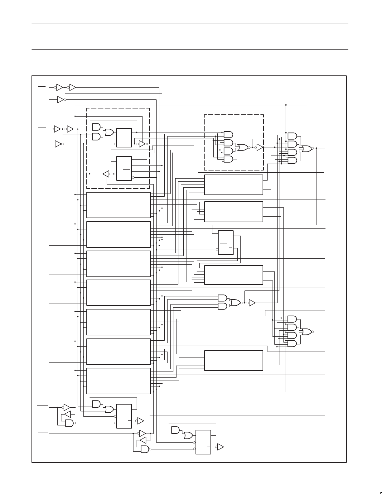
LOGIC DIAGRAM
21
CES
20
CPS
DETAIL A
DETAIL B
7
CER
CPR
6
18
A0
DQ
CP Q
D
Q
SEL
SEL
Q
CP
DETAIL B
23
PARITY
25
B0
DETAIL A
D
SEL
SEL
CP
DETAIL B
O
Q
DETAIL B
DETAIL B
17
A1
DETAIL A
16
A2
DETAIL A
15
A3
DETAIL A
14
A4
DETAIL A
13
A5
DETAIL A
12
A6
DETAIL A
26
27
28
1
2
9
3
4
B1
B2
B3
B4
B5
ERROR
B6
B7
11
A7
5
OEBR
19
OEAS
VCC= Pin 8
GND = Pin 22
1991 Jan 02
CP
CLR
QD
Q
QD
CP
Q
CLR
24
10
SF01042
FR
FS
5
 Loading...