

Page 1
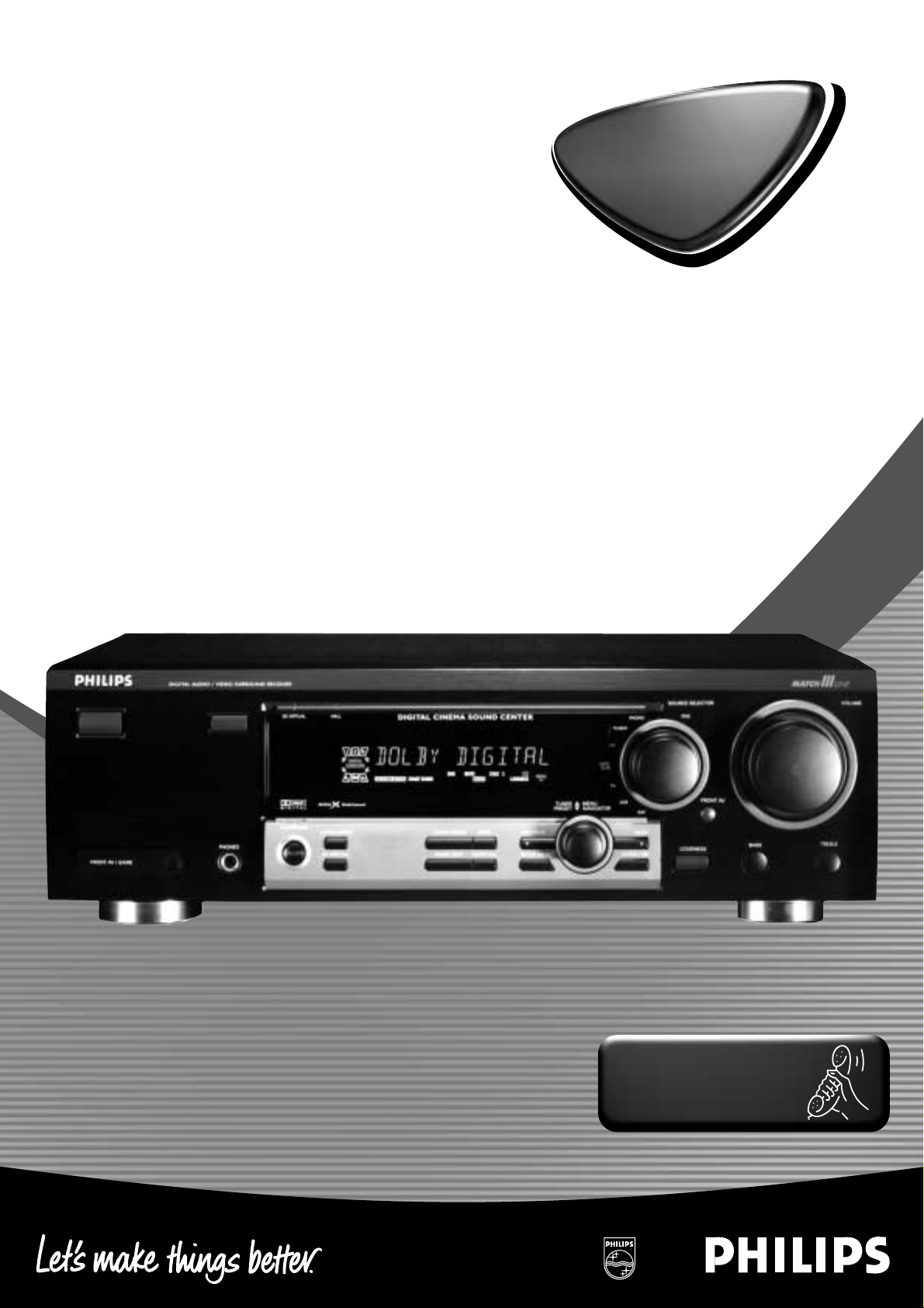
Digital surround sound r eceiver
Audio
Audio
MX-955
MX-965
MX-966
MX-990D
FR-965
FR-968
FR-975
Toll Free Help Line
Ligne d’assistance en service libre
Linea de ayuda telefónica sin cargo
800-531-0039
Page 2
Know these
ssaaffeettyysymbols
t
This “bolt of lightning” indicates
uninsulated material within your unit
may cause an electrical shock.For
the safety of everyone in your household,
please do not remove product covering.
s
The “exclamation point” calls attention
to features for which you should read
the enclosed literature closely to
prevent operating and maintenance problems.
WARNING: TO PREVENT FIRE OR
SHOCK HAZARD, DO NOT EXPOSE THIS
EQUIPMENT TO RAIN OR MOISTURE.
CAUTION: To prevent electric shock,
match wide blade of plug to wide slot, and
fully insert.
For Customer Use
Enter below the Serial No.which is located
on the rear of the cabinet.Retain this
information for future reference.
Model No. ___________________________
Serial No. ____________________________
• Once your Philips purchase is registered,you’re eligible to
receive all the privileges of owning a Philips product.
• So complete and return the Warranty Registration Card
enclosed with your purchase at once .And take advantage
of these important benefits.
Return your Warranty Registration card today to
ensure you receive all the benefits you’re entitled to.
Warranty
Verification
Registering your product within 10days
confirms your right to maximum
protection under the terms and
conditions of your Philips warranty.
Owner
Confirmation
Your completed Warranty Registration
Card serves as verification of ownership
in the event of product theft or loss.
Model
Registration
Returning your Warranty Registration
Card right away guarantees you’ll
receive all the information and special
offers which you qualify for as the
owner of your model.
Congratulations on your purchase,
and welcome to the “family!”
Dear Philips product owner:
Thank you for your confidence in Philips.You’ve selected one of the best-built,
best-backed products available today.And we’ll do everything in our power to
keep you happy with your purchase for many years to come.
As a member of the Philips “family,” you’re entitled to protection by one of the
most comprehensive warranties and outstanding service networks in the industry.
What’s more, your purchase guarantees you’ll receive all the information and
special offers for which you qualify,plus easy access to accessories from our
convenient home shopping network.
And most importantly you can count on our uncompromising commitment to
your total satisfaction.
All of this is our way of saying welcome–and thanks for investing in a Philips product.
Sincerely,
Robert Minkhorst
President and Chief Executive Officer
P.S. Remember,to get the most from your Philips product, you must
return your Warranty Registration Card within 10 days. So please
mail it to us right now!
Visit our World Wide Web Site at http://www.philipsusa.com
MAC5097
T
I
A
R
T
S
I
G
E
R
•
S
Y
Hurry!
A
D
0
1
I
N
O
N
N
E
E
D
E
D
W
I
T
H
CAUTION
RISK OF ELECTRIC SHOCK
DO NOT OPEN
CAUTION: TO REDUCE THE RISK OF ELECTRIC SHOCK, DO NOT
REMOVE COVER (OR BACK). NO USER-SERVICEABLE PARTS
INSIDE. REFER SERVICING TO QUALIFIED SERVICE PERSONNEL.
Page 3

3
English....................................................2
Français.................................................30
Español.................................................57
EnglishFrançaisEspañol
English: This digital apparatus does not exceed the Class B
limits for radio noise emissions from digital apparatus as set
out in the Radio Interference Regulations of the Canadian
Department of Communications.
Français : Cet appareil numérique n'émet pas de bruits
radioélectriques dépassant les limites applicables aux
appareils numériques de Classe B prescrites dans le
Règlement sur le Brouillage Radioélectrique édicté
par le Ministère des Communications du Canada.
Canada
Page 4
4
English
This product was designed and manufactured to meet strict
quality and safety standards. There are, however, some
installation and operation precautions which you should be
particularly aware of.
1. Read these instructions – All the safety and operating
instructions should be read before the appliance is
operated.
2. Keep these instructions – The safety and operating
instructions should be retained for future reference.
3. Heed all warnings – All warnings on the appliance
and in the operating instructions should be adhered to.
4. Follow all instructions – All operating and use
instructions should be followed.
5. Do not use this apparatus near water – for example,
near a bathtub, washbowl, kitchen sink, laundry tub, in a
wet basement or near a swimming pool, etc.
6. Clean only with a damp cloth. The appliance should
be cleaned only as recommended by the manufacturer.
7. Install in accordance with the manufacturers
instructions. Do not block any of the ventilation
openings. For example, the appliance should not be
situated on a bed, sofa, rug, or similar surface or placed
in a built-in installation, such as a bookcase or cabinet
that may impede the flow of air through the ventilation
openings.
8. Do not install near any heat sources such as
radiators, heat registers, stoves, or other apparatus
(including amplifiers) that produce heat.
9. Do not defeat the safety
purpose of the polarized or
grounding-type plug. A polarized
plug has two blades with one
wider than the other. A grounding type plug has two
blades and a third grounding prong. The wide blade or
the third prong are provided for your safety. When the
provided plug does not fit into your outlet, consult an
electrician for replacement of the obsolete outlet.
10. Protect the power cord from being walked on or
pinched particularly at plugs, convenience receptacles,
and the point where they exit from the apparatus.
11. Only use attachments/accessories specified by the
manufacturer.
12. Use only with a cart, stand, tripod, bracket,
or table specified by the manufacturer, or sold
with the apparatus. When a cart is used, use
caution when moving the cart/apparatus
combination to avoid injury from tip-over.
13. Unplug this apparatus during lightning storms or
when unused for long periods of time.
14. Refer all servicing to qualified service personnel.
Servicing is required when the apparatus has been
damaged in any way, such as power-supply cord or plug
is damaged, liquid has been spilled or objects have
fallen into the apparatus, the apparatus has been
exposed to rain or moisture, does not operate normally,
or has been dropped.
15. Battery usage
CAUTION– To prevent battery leakage
which may result in bodily injury or damage to the unit:
•
Install all batteries correctly, +and - as marked on the unit.
• Do not mix batteries (old and new or carbon and
alkaline, etc.).
•
Remove batteries when the unit is not used for a long time.
EL 6475-E001: 00/8
IMPORTANT SAFETY INSTRUCTIONS– Read before operating equipment
AC Polarized
Plug
Page 5
5
English
GENERAL INFORMATION
This receiver is supplied including:
– an universal remote control
– 2 batteries for the remote control, size AA
– a coaxial cable for audio connection with a DVD player
– a coaxial cable for video connection with a DVD player
or a TV set.
– a loop antenna
– a wire antenna
– 5 loudspeakers including 5 speaker cables (MX packages only)
– a subwoofer including a connection cable and a power cable
(MX packages only)
– a quick installation card (MX packages only)
– this instruction booklet
If you have stacked the components of your system, the
receiver must be on top. Place the receiver on a flat,
hard, stabile surface. Do not cover any vents and leave
50 cm (20 inches) above and 10 cm (4 inches) to the left
and right of the receiver clear for ventilation.
For good reception the loop antenna should not be placed on
top of or beneath VCRs, CD recorders, DVD players, TVs and
other radiation sources.
All redundant packing material has been omitted. We have
tried to make the packaging easy to separate into three mono
materials: cardboard (box), polystyrene foam (buffer) and
polyethylene (bags, protective foam sheet).
Your set consists of materials which can be recycled if
disassembled by a specialized company. Please observe the
local regulations regarding the disposal of packing materials,
dead batteries and old equipment.
Manufactured under license from Dolby Laboratories. “DOLBY”,
“DOLBY DIGITAL”,“PRO LOGIC” and the double-D symbol 2
are trademarks of Dolby Laboratories. Confidential unpublished
works. © 1992–1997 Dolby Laboratories. All rights reserved.
“DTS” and “DTS Digital Surround” are trademarks of Digital
Theater Systems, Inc. Copyright 1996 Theater Systems, Inc.
All Rights Reserved.
Trademark acknowledgement
Environmental information
Setup
Scope of supply
Safety instructions
Safety instructions......................................................................2 & 4
General information
Scope of supply..................................................................................5
Setup..................................................................................................5
Environmental information.................................................................5
Trademark acknowledgement............................................................5
Controls.................................................................................................6
Remote control
Remote control use ............................................................................7
Remote control buttons.....................................................................8
Programming the universal remote control.......................................9
Connectors..........................................................................................10
Connections
Analog audio connections...............................................................11
Digital audio connections................................................................11
System control bus, CINEMA LINK .................................................12
Video connections............................................................................12
Power...............................................................................................13
Speaker connections........................................................................13
TV as the center speaker.................................................................13
Antenna connections.......................................................................13
FRONT AV/ GAME cap (FR 975 only)..............................................13
System setup
Positioning the speakers..................................................................14
Receiver adjustment........................................................................14
Speaker setup and testing...............................................................15
Power handling................................................................................15
Headphones.....................................................................................15
Maintenance....................................................................................15
Subwoofer (supplied with MX packages only)
Subwoofer setup..............................................................................16
Connections......................................................................................16
Switching the subwoofer on............................................................16
Swiching the subwoofer to standby mode......................................16
Volume adjustment..........................................................................16
Phase selector..................................................................................16
Display.................................................................................................17
Menus
Receiver menu...........................................................................18–19
TV menu...........................................................................................19
Source selection
SOURCE SELECTOR..........................................................................20
6 CHANNEL / DVD INPUT selection................................................20
Reassigning a source selection.......................................................20
Using one source selection for two or more appliances................20
About 6 CHANNEL / DVD INPUT.....................................................20
Playback, recording
Playing a source ...............................................................................21
Adjusting the sound .........................................................................21
Recording from a source..................................................................21
Recording from the digital output ...................................................21
Surround sound
About surround sound......................................................................22
Switching surround sound...............................................................22
Surround sound settings ..................................................................23
Tuner
Tuning to radio stations...................................................................24
Switching FM sensitivity.................................................................24
Storing radio stations......................................................................24
Tuning to stored radio stations........................................................25
Resorting stored radio stations.......................................................25
Naming radio stations.....................................................................25
Clearing station names ....................................................................25
Technical data
Receiver............................................................................................26
Speakers (supplied with MX packages only)..................................27
Troubleshooting
Warning............................................................................................28
Troubleshooting................................................................................28
Limited warranty
Limited warranty..............................................................................29
As an ENERGY STAR®partner, Philips has determined that
this product meets the ENERGY STAR
®
guidelines for energy efficiency.
Page 6
6
English
CONTROLS
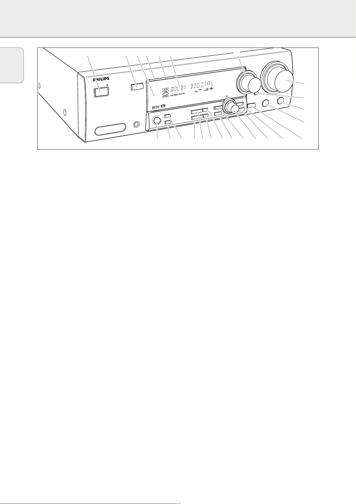
1 POWER / STANDBY.......Switches the receiver on and off.
2 CINEMA LINK................Switches on and off the system
control bus between the receiver
and the TV.
3 ..........................................Sensor for the infrared remote
control.
4 3D SURROUND..............Control light for virtual
3D surround (FR 965, FR 968).
VIRTUAL..........................Control light for virtual surround
(FR 975).
5 HALL................................Control light for HALL.
6 ..........................................Display
7 SOURCE SELECTOR......Selects the different audio and
video connectors.
8 VOLUME..........................Increases and decreases the
volume level.
9 FRONT AV .......................Selects the FRONT AV / GAME
input (FR 975).
0 TREBLE............................Adjusts the treble when used in
combination with VOLUME.
! BASS...............................Adjusts the bass when used in
combination with VOLUME.
@ LOUDNESS.....................Switches LOUDNESS on and off.
# NEXT 2 ...........................TUNER: searches radio stations.
MENU: switches to the next
menu level.
$ ENTER / OK.....................Confirms selected menu values.
% TUNER PRESET X MENU NAVIGATOR
TUNER: switches to the next and
previous stored radio station.
MENU: moves upwards and
downwards.
^ 1 PREV. / EXIT TUNER: searches radio stations.
MENU: switches to the previous
menu level.
& SETUP MENU ................Switches the menu on and off.
* SENS. ..............................Switches between low and high
tuner sensitivity.
( DISPLAY..........................Switches the brightness of the
display.
) TUNER BAND ................Switches the wavebands of the
tuner.
¡ NAME/FREQUENCY......Switches between name and
frequency display.
™ SURR. MODE ..................Switches through the different
speaker configurations.
£ 3D SURROUND..............Switches virtual 3D surround on
and off (FR 965, FR 968).
VIRT. MODE....................Scrolls through the different
virtual surround sound modes
(FR 975).
≤ SURROUND ON/OFF.....Switches between the last
selected surround mode and
stereo.
1 234 56 7
L
L
A
K
IN
L
A
M
E
IN
DBY
AN
ER / ST
POW
E
AM
V / G
T A
N
FRO
C
PHONES
H
L
A
U
T
IR
V
SURR. MODE
UND
SURRO
VIRT. M
ON/OFF
R
O
T
C
E
L
E
S
E
C
R
U
O
S
D
V
D
O
N
O
H
P
R
E
N
U
R
E
T
N
E
C
D
N
U
O
S
A
M
E
IN
C
L
A
T
I
G
I
D
PREV. / EXIT
SENS.
NER BAND
TU
R
F
/
E
M
A
N
PROCESSING
SOUND
ODE
DIGITAL
TETRACORE
SETU
DISPLAY
Y
C
N
E
U
Q
E
T
D
C
/
CDR
APE
T
TV
VCR
U
T
N
E
SA
M
R
O
T
R
A
E
N
IG
V
U
A
T
N
T
E
S
E
R
P
ENU
P M
NEXT
TER / OK
AV
L
B
E
R
T
S
S
A
B
S
S
E
N
D
U
O
L
^
E
M
U
L
O
V
8
E
9
0
!
@#$%&*()¡™£≤
Page 7
7
English
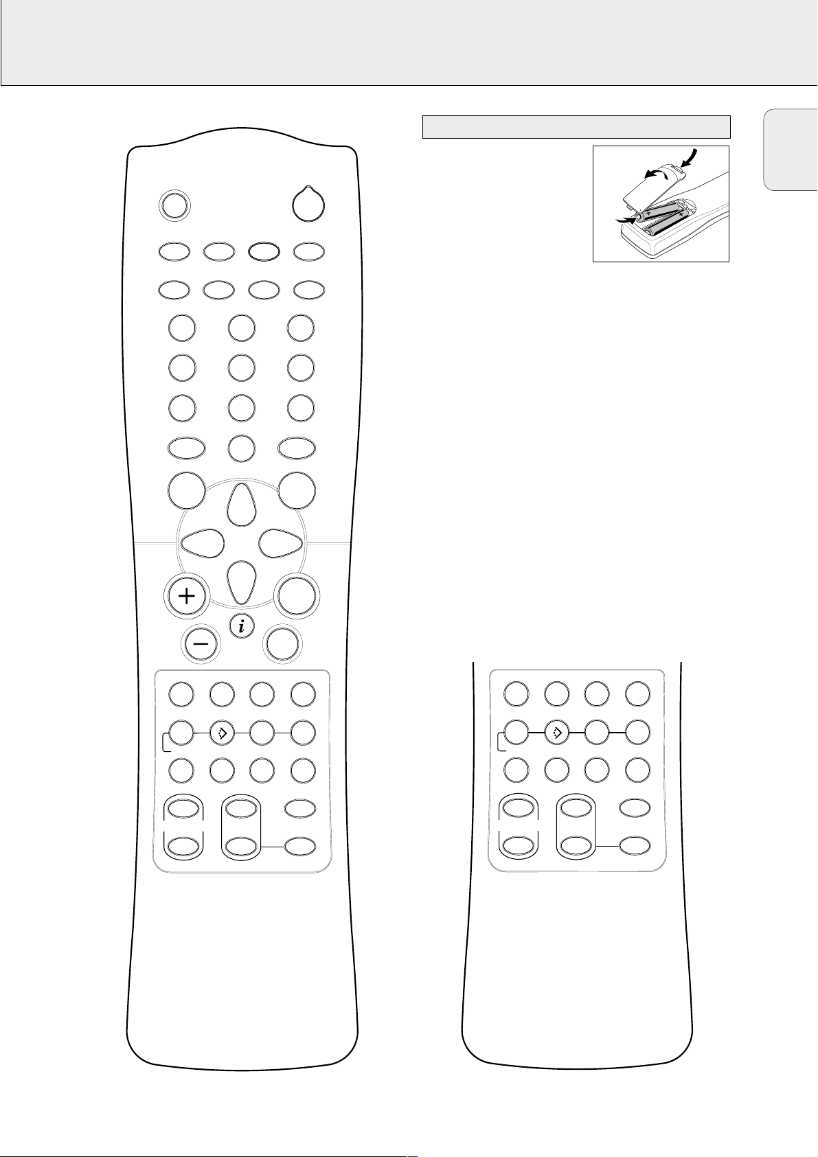
REMOTE CONTROL
Open the battery compartment
of the remote control and insert
2 alkaline batteries, type AA
(R06, UM-3).
Remove batteries if they are
dead or if the remote control
will not be used for a long time.
Batteries contain chemical substances, so they should
be disposed of properly.
The buttons on the remote control work the same way as the
corresponding ones on the receiver.
Important!
You have to press a source button for longer than 1second to
switch the sound source on the receiver. Pressing a source
button for less than 1 second will only switch the remote
control to use the commands for the selected product.
The remote control remains tuned to the selected source until
another source button on the remote control is pressed. This
enables you to operate additional sources (i. e. winding a
tape) without changing the source on the receiver.
Remote control use
MUTE
H
PHONO
TV
CINEMA LINK
GUIDE
1
4
7
ON/OFF
MENU
TUNER
VCR
CD CDR/TAPE
SAT
2
5
8
0
2
DVD
3
6
9
CABLE BOX
OK
É
SUBW.
ON/
OFF
T-C
SURROUND
ON/
OFF
SURROUND
MODE
TEST TONE
TV
AA
NEWS/TA
CHANNEL/TRACK LOUDNESS
íë
REC CANCEL FR.D. INDEX
AUDIO
DVD
DISC
REAR
+
SUB WOOFER
-
CHANNEL
Ç
Å
VIRTUALNIGHT
MODE
+
-
CHANNEL/TRACK LOUDNESS
íë
REC CANCEL FR.D. INDEX
AUDIO
DVD
DISC
+
SUB WOOFER
-
Å
3D SURR.NIGHT
REAR
+
-
CHANNEL
SOUND
±
T-C
SURROUND
ON/
OFF
SURROUND
MODE
TEST TONE
FR 975
FR 965, FR 968
Page 8

8
English
REMOTE CONTROL
H MUTE .....................Mutes the sound of the receiver in all
modes, except TV.
Mutes the sound of your Philips TV set
if your remote control is in TV mode.
2 ................................Switches the source selected on your
remote control (e.g. VCR, TV) to standby.
When pressed longer than 2 seconds,
the receiver switches to standby.
PHONO, TUNER, CD,
CDR/TAPE, TV,
VCR, SAT, DVD..............Switches the remote control to the
commands of the different products.
Selects the sources if pressed longer
than 1 second. SAT only works with
digital satellite receivers.
1–0................................Keys in numbers for tracks, stations or
frequencies. Numbers consisting of
two figures must be keyed in within
2 seconds.
CINEMA LINK ON/OFF...
Switches the system connection
between the receiver and the TV on
and off.
CABLE BOX...................(USA only) Switches the remote
control to the cable box codes.
MENU GUIDE..............TUNER: Switches the receiver menu
on and off.
DVD, TV: Switches the DVD/TV menu
on and off.
OK.................................Confirms menu options.
Arrow buttons..............TUNER: Moves in the menus.
Right/left arrows are tuning up/down.
CD, CDR: Left/right arrows are
searching backwards/forwards,
up/down arrows are selecting the
next/previous track.
+A...........................Increases the receiver volume.
-A...........................Decreases the receiver volume.
i NEWS/TA.................TUNER:Without function.
TV: Switches teletext on and off.
SAT: Switches the information text on
and off.
ÉATV......................Increases the TV volume.
CD, CDR, VCR, DVD: Starts playback.
ÇATV......................Decreases the TV volume.
CD, CDR, VCR, DVD: Stops playback.
í
CHANNEL/TRACK
...Selects the previous preset tuner
station.
VCR: Rewinds the tape.
CD, CDR, DVD: Selects the previous
track.
TV:Selects the previous channel.
ë
CHANNEL/TRACK
...Selects the next preset tuner station.
VCR: Fast forwards the tape.
CD, CDR, DVD: Selects the next
track.
TV:Selects the next channel.
LOUDNESS...................Switches LOUDNESS on and off.
±SOUND ....................Scrolls through the different smart
sounds (FR 965, FR 968 only).
SUBW. ON/OFF............Switches the subwoofer on and off
(FR 975 only).
REC, DVD AUDIO ..........CDR, VCR: Starts recording.
DVD: Switches audio tracks.
CANCEL, DVD ...........CD, CDR, SAT, VCR: Clears a
program, cancels selections.
DVD: Switches the view angle.
FR.D., DVD Å .............TUNER: Switches to FREQUENCY
DIRECT.
CD, CDR, VCR, DVD: Pauses
playback.
INDEX, DVD T-C............VCR: Switches the index search on
and off.
SAT: Switches the themes on and off.
DVD: Switches between title and
chapter.
DISC..............................CD-, CDR-, DVD-Changers:
Switches to the next disc.
NIGHT...........................Switches NIGHT MODE on and off.
3D SURR.......................Switches virtual 3D surround on and off
(FR 965, FR 968).
VIRTUAL MODE............Scrolls through the different virtual
surround sound modes (FR 975 only).
SURROUND ON/OFF....
Switches SURROUND SOUND on and off.
+/- SUBWOOFER...Increases/decreases the subwoofer
volume.
+/- REAR...............Increases/decreases the volume of the
rear speakers. While test tone is on,
the volume of the speakers you are
hearing can be increased/decreased
with these buttons.
SURROUND MODE.......Scrolls through the different surround
modes.
TEST TONE...................Switches the test tone on and off.
While test tone is on, the volume of
the speakers you are hearing can be
increased/decreased with
+/- REAR.
Remote control buttons
Page 9

9
English
REMOTE CONTROL
You can identify the universal remote control by the
inscription Multibrand/Universal.
The universal remote control must be programmed to use the
codes for your appliances of different brands. This is done by
keying in a 4-digit code or by scanning the codes until the
correct one is found. We recommend to using the 4-digit
code. This method is faster and more reliable. The code
scanning method should be used only if you cannot find the
code for one of your appliances. The codes are listed at the
end of this book.
Important!
Use the remote control buttons for programming, not the
buttons of the receiver or other appliances.
Programming with the 4-digit code
1 Keep the source button for the appliance which should be
controlled and2 pressed for 3 seconds.
2 Key in the 4-digit code for the appliance (codetable at the
end of the booklet).
Notes:– If more than 4 digits are entered, the remote control
will recognize only the ones keyed in first.
– If you do not key in a code within 30 seconds the
remote control will switch off the programming
function without changing the code.
– To program a new appliance, simply overwrite the
old code by entering a new one.
Scanning the codetable
1 Switch on the appliance which should be controlled.
2 Keep the source button for the appliance which should be
controlled and2 pressed for 3 seconds.
3 Press and release 2 again.
yThe remote control sends the codes for channel up or
standby (depending on the selected source) for one
brand after the other.
4 As soon as the appliance reacts – switches to the next
channel or to standby – press 2 to confirm the code.
yThe identified code will be used.
• If the set does not react within 2 minutes, the code for this
appliance is not stored in the remote control. The code of
the remote control will remain unchanged.
Note: When taking out the batteries of the remote control for
more than 1 minute the codes must be reprogrammed.
Once you have found and tested the codes for your various
appliances, you may want to write them down here.
PHONO..........................................
TUNER...........................................
CD .................................................
CDR/TAPE .....................................
TV..................................................
VCR ...............................................
SAT................................................
DVD...............................................
CABLE BOX...................................
Resetting the remote control
1 Keep one of the source buttons and 2 pressed for
3 seconds.
2 Key in the 3-digit code 981.
yThe remote control is now reset to all its original Philips
codes.
Programming the universal remote control
Page 10
10
English
CONNECTORS
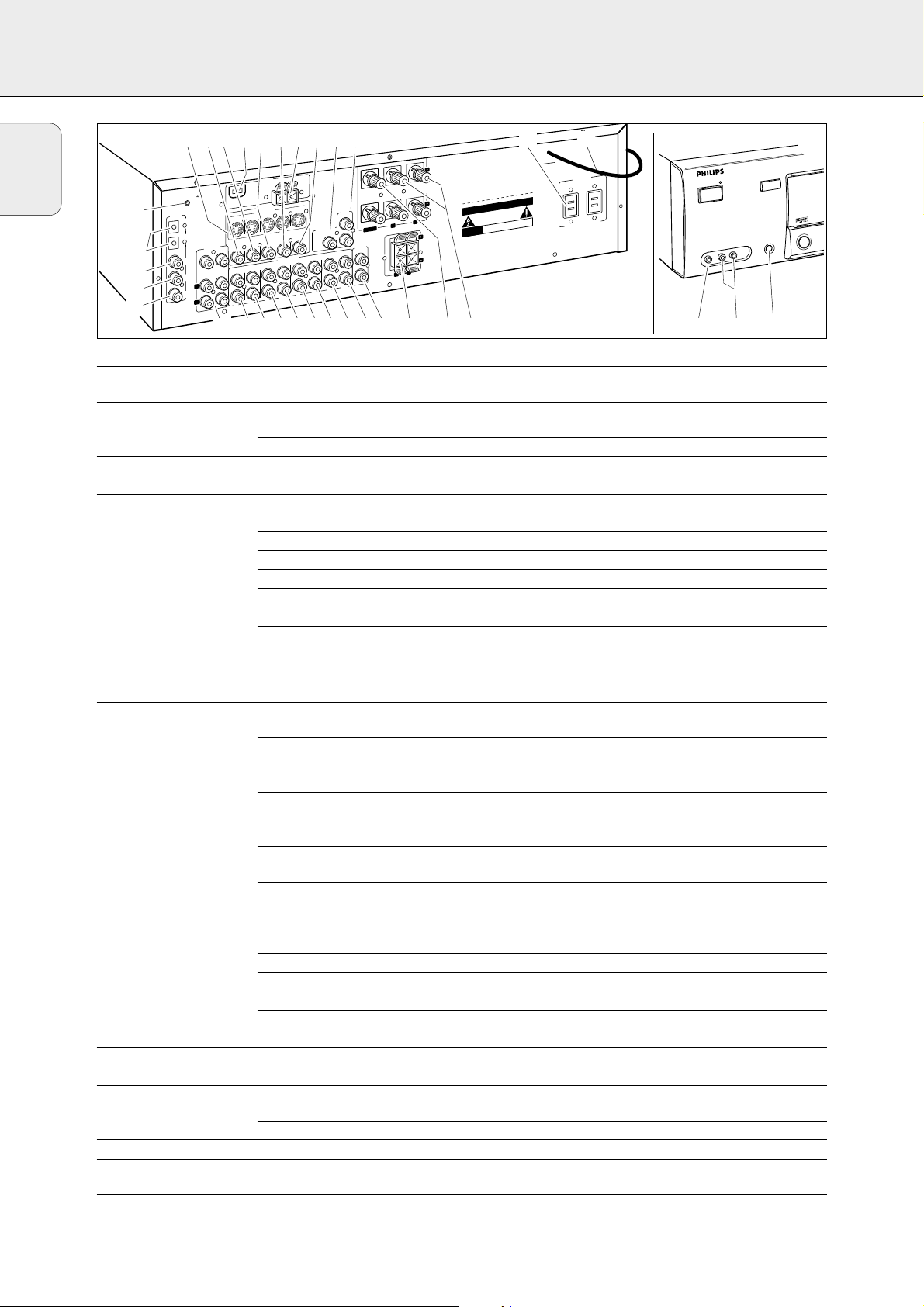
Connectors Connectors name Connect to:
6.3 mm headphone jack 1 PHONES A headphone with a 6.3 mm plug.
at the front.
Audio and video inputs 2 FRONT AV / GAME Left and right audio out jacks of appliances such as video cameras
at the front and game consoles.
(FR 975 only).
3 FRONT AV / GAME Video out jacks of appliances such as video cameras and game consoles.
FRONT SPEAKERS 4 R, L Right and left front speaker.
5 CENTER Center speaker.
SURROUND SPEAKERS 6 R, L Right and left surround speaker.
AUDIO IN/OUT 8 CDR/TAPE OUT Input of a CD recorder or a tape deck.
9 CDR/TAPE IN Output of a CD recorder or a tape deck.
0 CD IN Output of a CD player.
! SAT IN Output of a satellite system.
@ VCR OUT Input of a video recorder.
# VCR IN Output of a video recorder.
$ TV IN Output of a TV.
% PHONO IN Output of a turntable with MM coil.
¡ PHONO GND f Ground cable of a turntable.
6 CHANNEL / DVD INPUT ^
6 CHANNEL / DVD INPUT
6 channel output of appliances such as DVD or laserdisc players.
DIGITAL AUDIO IN/OUT & COAX 1 IN Coaxial output of digital appliances (default input for source DVD).
(FR 975 only)
& COAX OUT Coaxial input of digital appliances such as CD recorders or MD recorders
(FR 965, FR 968 only).
* COAX 2 IN Coaxial output of digital appliances.
( COAX OUT Coaxial input of digital appliances such as CD recorders or MD recorders
(FR 975 only).
( COAX 1 IN Coaxial output of digital appliances (FR 965, FR 968 only).
) OPTICAL IN Optical output of digital appliances such as DVD players, CD players,
CD recorders or MD players (FR 965, FR 968 only).
) OPTICAL 1 (2) IN Optical output of digital appliances such as DVD players, CD players,
CD recorders or MD players (FR 975 only).
VIDEO IN/OUT ™ S-VIDEO S-Video inputs/outputs of video appliances for better video quality
(FR 968, FR 975 only).
£ DVD IN Output of a DVD player.
≤ MON OUT Input of a monitor (e. g. the TV).
§ VCR IN Output of a video recorder.
≥ VCR OUT Input of a video recorder (for recording).
ª SAT IN Output of a satellite system.
Antenna connectors ∞ AM LOOP Frame antenna supplied.
• FM 300 Ω Wire antenna supplied or exterior antenna.
Preamplified outputs 7 CENTER PRE-OUT Input of a TV when it is used as the center speaker (only possible
when the CINEMA LINK system bus is connected).
º SUBWOOFER PRE-OUT Input of a powered subwoofer.
System control bus ⁄ CINEMA LINK System control bus jacks of a Philips TV with CINEMA LINK.
Power outlets ¤ AC OUTLET Supplies same voltage as mains. Up to 120 W/1A total permitted load.
(not on all versions)
Power cord ‹ After all other connections have been made, connect the
power cord to the wall outlet.
O
U
T
V
C
R
¤‹
CAUTION
K
C
O
H
S
IC
R
T
C
E
L
E
F
O
K
N
IS
E
P
O
T
O
N
O
D
RISQUE DE CHOC ELECTRIQUE
NE PAS OUVRIR
nder license from Dolby Laboratories.
ITAL“, ”PRO LOGIC“ and the
DIG
arks of Dolby Laboratories.
s,
t 1996 Digital Theater System
TLET
AC OU
120V - 60 Hz
120W/1A MAX. SWITCHED
POWER / STANDBY
K
N
I
L
A
M
E
N
I
C
D
N
U
O
R
R
U
S
S
E
N
O
F
H
F
P
O
/
N
O
14567890!@#$
23%^
¡
)
(
*
&
™£≤∞§≥•ªº
A
N
N
E
T
N
A
Ω
0
30
M
.
D
N
G
O
N
O
H
P
L
A
T
I
G
I
D
IO
D
U
A
T
U
O
/
N
I
P
O
P
O
O
C
O
O
C
O
C
A
2
L
A
IC
T
IN
1
L
A
C
I
T
IN
L/
E
N
N
A
H
C
6
T
U
P
IN
D
V
D
.
W
B
U
S
ER
T
CEN
X
A
T
U
P
T
ON
FR
.
RR
2
X
SU
A
IN
L
1
X
A
N
I
R
F
P
O
O
L
M
O
/
IN
O
DE
I
O
T
E
A
ID
S
-V
S
R
VC
N
O
M
D
V
D
IN
IN
Y
N
A
L
O
P
M
UT
VD
O
D
IN
V
T
O
N
O
H
IN
IN
PLAY
IN
U
S
T
A
S
T
U
IN
O
C
R
E
C
R
V
T
U
/O
D
C
IN
IO
D
U
A
T
A
S
R
C
V
IN
IN
OUT
REC
⁄
FRONT
SPEAKERS
EACH SPEAKER ≥ 6 Ω
CINEMA
LINK
R
FE
O
O
W
CENTER
B
T
U
-O
E
R
P
R
E
T
N
E
C
T
U
O
-
E
R
P
E
P
A
T
/
R
D
C
OUT
IN
REC
PLAY
L
R
O
R
R
U
S
K
A
E
P
S
L
R
Ω
≥ 6
PEAKER
S
EACH
D
N
U
S
R
E
R
AVIS
Designed and developed by Philips in the European
munity.
Com
anufactured u
M
”DOLBY“, ”DOLBY
double-D Symbol are tradem
Confidential Unpublished Works.
©1992–1997 Dolby Laboratories. All rights reserved.
anufactured under license from Digital Theater
M
Systems. Inc. US Pat. No. 5,451,942 and other world-
ide patents issued and pending. ”DTS“ and ”DTS
w
Digital Surround“ are trademarks of Digital Theater
Systems, Inc. Copyrigh
Inc. All Rights Reserved.
Page 11
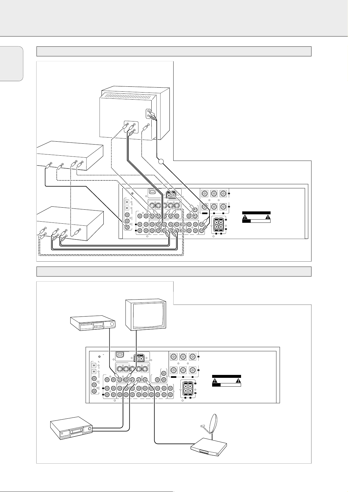
11
English
CONNECTIONS
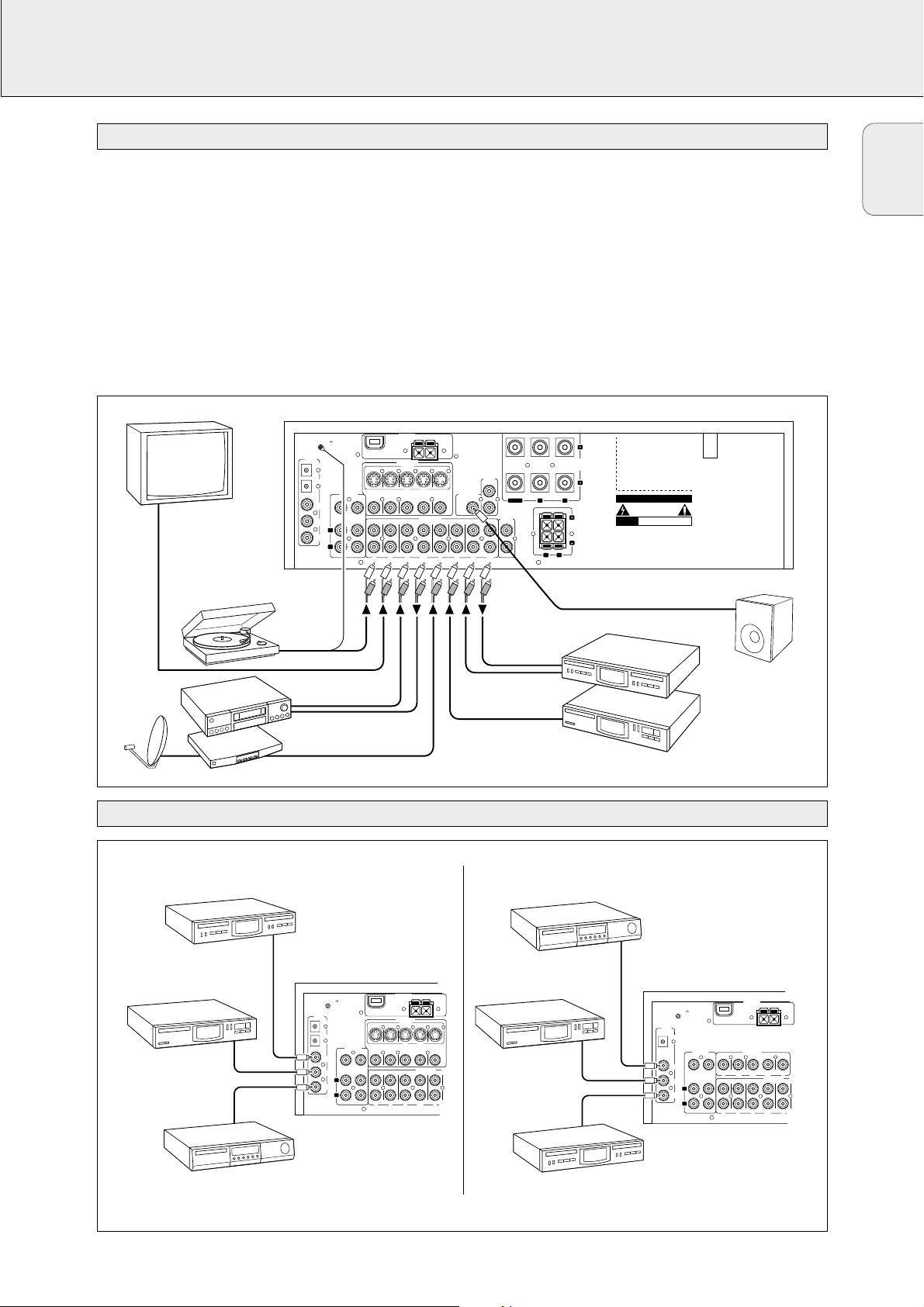
Digital audio connections
Analog audio connections
There are analog and digital connectors available on some
appliances. If possible use the digital connection; usually this
will result in better sound quality. See “Reassigning a source
selection” on how to use the digital connectors of the receiver.
Because of a different kind of output signal, the use of Dolby
Digital Laserdisc requires an optional AC-3 RF demodulator.
DTS Digital Surround
TM
is a discrete 5.1-channel digital audio
format available on CD, LD, and DVD software which
consequently cannot be decoded and played back inside most
CD, LD, or DVD players. For this reason, when DTS-encoded
software is played back through the analog outputs of the CD,
LD, or DVD player, excessive noise will be exhibited. To avoid
possible damage to the audio system, proper precautions
should be taken by the customer if the analog outputs are
connected directly to the receiver.
Only for FR975: To enjoy DTS Digital SurroundTMplayback,
a DTS-compatible player has to be connected to one of the
digital inputs of the receiver.
ANTENNA
DIGITAL
AUDIO
IN/OUT
PHONO
VCRTV SAT CD CDR/TAPE
AUDIO IN/OUT
IN IN
IN
PLAY
OUT
REC
IN IN
IN
PLAY
OUT
REC
PRE-OUT
CENTER
CAUTION
RISK OF ELECTRIC SHOCK
DO NOT OPEN
AVIS
RISQUE DE CHOC ELECTRIQUE
NE PAS OUVRIR
Designed and developed by Philips in the European
Community.
Manufactured under license from Dolby Laboratories.
”DOLBY“, ”DOLBY DIGITAL“, ”PRO LOGIC“ and the
double-D Symbol are trademarks of Dolby
Laboratories. Confidential Unpublished Works.
©1992–1997 Dolby Laboratories. All rights reserved.
Manufactured under license from Digital Theater
Systems. Inc. US Pat. No. 5,451,942 and other worldwide patents issued and pending. ”DTS“ and ”DTS
Digital Surround“ are trademarks of Digital Theater
Systems, Inc. Copyright 1996 Digital Theater Systems,
Inc. All Rights Reserved.
PHONO GND.
SURROUND
SPEAKERS
R
L
EACH SPEAKER ≥ 6 Ω
CENTER
R L
FRONT
SPEAKERS
EACH SPEAKER ≥ 6 Ω
AM LOOP
DVD
IN
MON
OUT
VCR
SAT
IN
PRE-OUT
CINEMA
LINK
SUBWOOFER
IN
PLAY
OUT
REC
OPTICAL 1
IN
COAX
OUT
COAX 2
IN
R
L
SURR.
CENTER SUBW.
FRONT
6 CHANNEL /
DVD INPUT
OPTICAL 2
IN
FM 300 Ω
COAX 1
IN
2
ANTENNA
VIDEO IN/OUT
S-VIDEO
DVD MON SAT
VCRVCR
IN OUT
AUDIO
OUT
TURNTABLE
AUDIO IN
AUDIO OUT
IN
OUT
VCR
SAT RECEIVER
CD RECORDER
CD PLAYER
MONITOR / TV
POWERED
SUBWOOFER
FR 975
FR 975
CD RECORDER
CD PLAYER
DVD PLAYER
PHONO GND.
DIGITAL
AUDIO
IN/OUT
OPTICAL 2
IN
OPTICAL 1
IN
6 CHANNEL /
DVD INPUT
CENTER SUBW.
COAX
OUT
COAX 2
SURR.
IN
L
COAX 1
IN
R
AM LOOP
DVD MON SAT
DVD
MON
IN
OUT
FRONT
PHONO
IN IN
ANTENNA
FM 300 Ω
VIDEO IN/OUT
S-VIDEO
VCRVCR
IN OUT
IN
OUT
VCR
PLAY
REC
AUDIO IN/OUT
VCRTV SAT
IN
OUT
PLAY
REC
SAT
IN
IN
FR 965, FR 968
DVD PLAYER
CD PLAYER
CD RECORDER
PHONO GND.
DIGITAL
AUDIO
IN/OUT
OPTICAL IN
COAX 1
IN
COAX 2
IN
COAX
OUT
ANTENNA
FM 300 Ω
AM LOOP
6 CHANNEL /
DVD INPUT
CENTER
SURR.
L
R
VIDEO IN/OUT
SAT
MON
VCR
DVD
SUBW.
IN
OUT
IN
OUT
IN
PLAY
REC
PHONO
IN IN
IN
PLAY
AUDIO IN/OUT
VCRTV SAT
OUT
REC
IN
FRONT
Page 12
12
English
CONNECTIONS
System control bus, CINEMA LINK
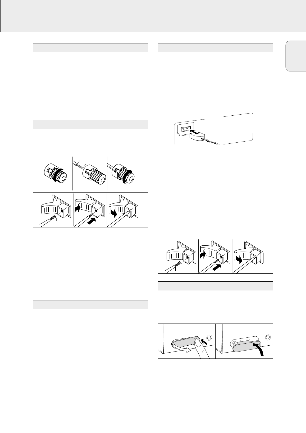
Video connections
If the receiver and your Philips TV (or even better in addition
a Philips VCR or DVD player) with Cinemalink are connected
with the CINEMA LINK system bus control, some extra
system benefits are offered:
– Upon starting a source, the system will automatically
switch to that input.
– You may control the system via the TV screen. Depending
on the language of the TV, this can be done in your
preferred language.
– The TV can function as the center speaker of your system,
making a separate center speaker unnecessary.
(The cable A has to be purchased separately.)
– By pressing the standby button on the remote control, you
can switch the complete system to standby.
DIGITAL
AUDIO
IN/OUT
PHONO
VCRTV SAT CD CDR/TAPE
AUDIO IN/OUT
IN IN
IN
PLAY
OUT
REC
IN IN
IN
PLAY
OUT
REC
PRE-OUT
CENTER
CAUTION
RISK OF ELECTRIC SHOCK
DO NOT OPEN
AVIS
RISQUE DE CHOC ELECTRIQUE
NE PAS OUVRIR
PHONO GND.
SURROUND
SPEAKERS
R L
EACH SPEAKER ≥ 6 Ω
CENTER
R L
FRONT
SPEAKERS
EACH SPEAKER ≥ 6 Ω
AM LOOP
DVD
IN
MON
OUT
VCR
SAT
IN
PRE-OUT
CINEMA
LINK
SUBWOOFER
IN
PLAY
OUT
REC
OUT
OPTICAL 1
IN
COAX
OUT
COAX 2
IN
R
L
SURR.
CENTER SUBW.
FRONT
6 CHANNEL /
DVD INPUT
OPTICAL 2
IN
FM 300 Ω
COAX 1
IN
Designed and developed by Philips in the European
Community.
Manufactured under license from Dolby Laboratories.
”DOLBY“, ”DOLBY DIGITAL“, ”PRO LOGIC“ and the
double-D Symbol are trademarks of Dolby
Laboratories. Confidential Unpublished Works.
©1992–1997 Dolby Laboratories. All rights reserved.
Manufactured under license from Digital Theater
Systems. Inc. US Pat. No. 5,451,942 and other worldwide patents issued and pending. ”DTS“ and ”DTS
Digital Surround“ are trademarks of Digital Theater
Systems, Inc. Copyright 1996 Digital Theater Systems,
Inc. All Rights Reserved.
2
VIDEO IN/OUT
DVD MON SAT
VCRVCR
IN
S-VIDEO
ANTENNA
VCR
V
ID
E
O
IN
A
U
D
IO
O
U
T
C
IN
E
M
A
LIN
K
V
ID
E
O
O
U
T
DIGITAL
OUT
CINEM
A LINK
V
ID
E
O
AUDIO
CINEM
A LINK
IN/REC
OUT/PLAY
L
IN
REC
OUT
PLAY
DVD PLAYER
TV
C
E
N
T
E
R
IN
R
A
FR 975
ANTENNA
DIGITAL
AUDIO
IN/OUT
PHONO
VCRTV SAT CD CDR/TAPE
AUDIO IN/OUT
IN IN
IN
PLAY
OUT
REC
IN IN
IN
PLAY
OUT
REC
PRE-OUT
CENTER
CAUTION
RISK OF ELECTRIC SHOCK
DO NOT OPEN
AVIS
RISQUE DE CHOC ELECTRIQUE
NE PAS OUVRIR
PHONO GND.
SURROUND
SPEAKERS
R
L
EACH SPEAKER ≥ 6 Ω
CENTER
R L
FRONT
SPEAKERS
EACH SPEAKER ≥ 6 Ω
AM LOOP
DVD
IN
MON
OUT
VCR
SAT
IN
PRE-OUT
CINEMA
LINK
SUBWOOFER
IN
PLAY
OUT
REC
OPTICAL 1
IN
COAX
OUT
COAX 2
IN
R
L
SURR.
CENTER SUBW.
FRONT
6 CHANNEL /
DVD INPUT
OPTICAL 2
IN
FM 300 Ω
COAX 1
IN
Designed and developed by Philips in the European
Community.
Manufactured under license from Dolby Laboratories.
”DOLBY“, ”DOLBY DIGITAL“, ”PRO LOGIC“ and the
double-D Symbol are trademarks of Dolby
Laboratories. Confidential Unpublished Works.
©1992–1997 Dolby Laboratories. All rights reserved.
Manufactured under license from Digital Theater
Systems. Inc. US Pat. No. 5,451,942 and other worldwide patents issued and pending. ”DTS“ and ”DTS
Digital Surround“ are trademarks of Digital Theater
Systems, Inc. Copyright 1996 Digital Theater Systems,
Inc. All Rights Reserved.
2
S-VIDEO
DVD MON SAT
VCR
VCR
VIDEO IN/OUT
OUT
IN
DVD PLAYER
MONITOR / TV
VIDEO IN
VIDEO OUT
VCR
SAT RECEIVER
FR 975
If your video products have a S-video connector, using this
connector will provide better video quality
(FR 968, FR 975 only).
Page 13
13
English
CONNECTIONS
The type plate is located on the rear of the receiver.
1 Check whether the power voltage as shown on the type
plate corresponds to your local power voltage. If it does
not, consult your dealer or service organization.
2 Connect the power cord to the power outlet.
To disconnect the unit from the power completely, remove the
power plug from the power outlet.
Some of the speaker connections on the receiver are screw
connectors and some are click-fit connectors. Use them as
shown below.
1 Always connect the colored (or marked) wire to the colored
terminal and the black (or unmarked) wire to the black
terminal.
2 Connect:
– Left front speaker to L (red and black)
– Right front speaker to R (red and black)
– Center speaker to CENTER (blue and black)
– Left surround speaker to SURROUND L (grey and black)
– Right surround speaker to SURROUND R (grey and black)
You may use your Philips TV with CINEMALINK as the center
speaker. For TV’s with cinch connectors, additional cinch
cables are needed. These cables must be connected to the
blue CENTER PRE-OUT connector on the back. Look into the
instruction manual of your TV on how to use it as the center
speaker.
AM (MW) antenna
The loop antenna supplied is for indoor use only. Position the
antenna as far away as possible from the receiver, a TV, the
cables, a DVD player, a VCR and other radiation sources.
1
Fit the plug of the frame antenna to AM LOOP as shown below.
2 Turn the antenna for optimum reception.
FM antenna
The wire antenna supplied can be used only to receive nearby
stations. For better reception we recommend using a cable
antenna system or an outdoor antenna.
1 Open the FM 300 Ω click-fits by pushing the lever down as
shown below.
2 Insert each wire of the antenna into one hole.
3 Close the click-fits using the lever.
4
Move the antenna in different positions for optimum reception.
• To remove the FRONT AV / GAME cap, press on the right
side of the cap.
• Insert the cap from below to close the compartment.
The unit complies with the FCC-Rules, Part 15.
Operation is subject to the following two conditions:
1. This device may not cause harmful interference, and
2. This device must accept any interference received,
including interference that may cause undesired
operation.
FRONT AV /GAME cap (FR 975 only)
Antenna connections
TV as the center speaker
Speaker connections
Power
7 mm
1
2
3
ANTENNA
P
O
LO
AM
8 mm
1
2
3
8 mm
1
2
3
S
E
N
O
H
P
E
M
A
/ G
V
T A
N
O
R
F
FRONT A
V / GAM
E
H
P
S
E
N
O
Page 14

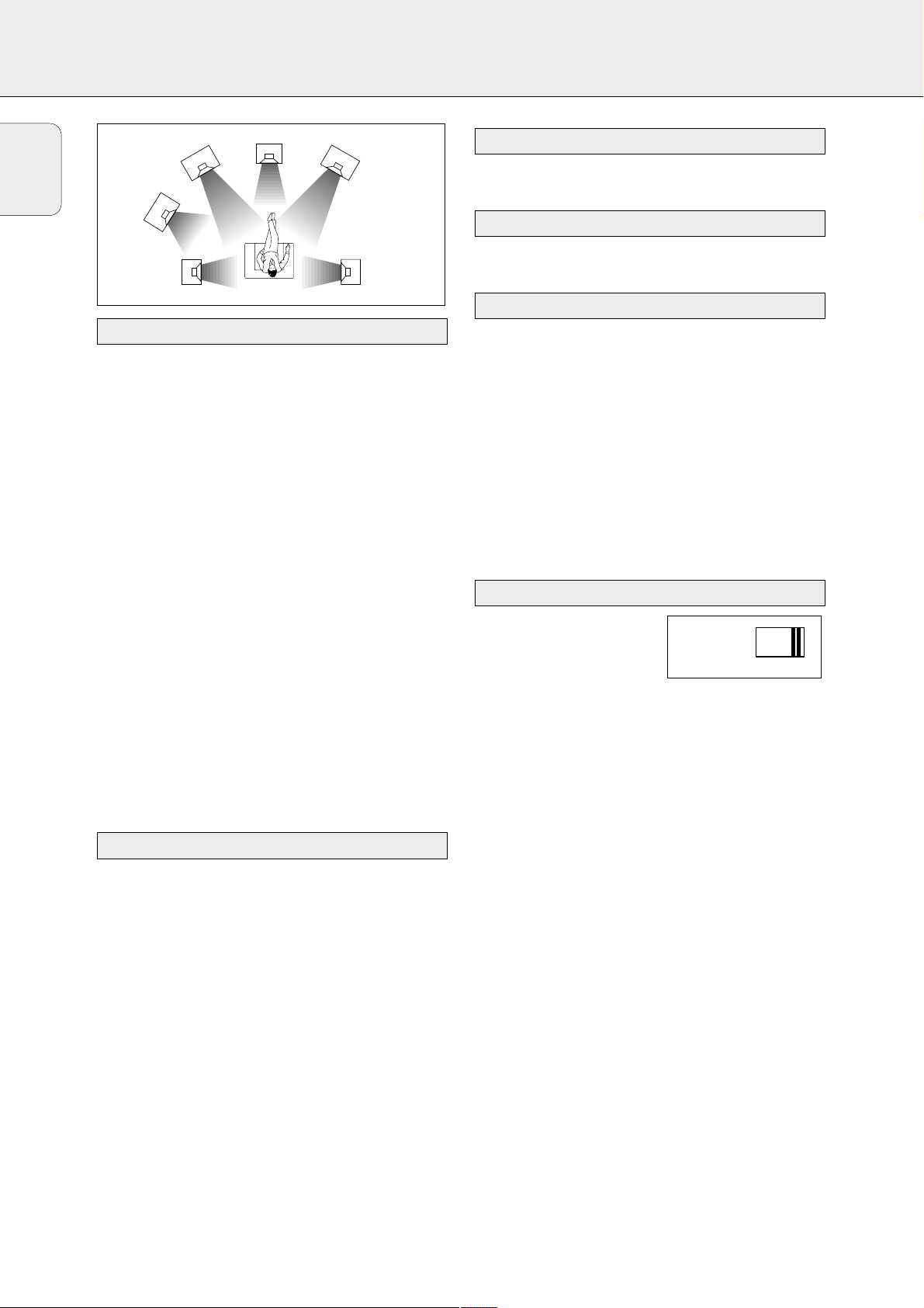
General hints for positioning
Avoid positioning the speakers in a corner or on the floor as
this will boost the bass tones too much. Placing the speakers
behind curtains, furniture, etc. will reduce the treble
response. The listener should always be able to ”see” the
speakers.
Each room has different acoustic characteristics and the
positioning possibilities often are limited. You can find the
best position for your speakers by referring to the picture
above.
As a minimum we recommend 5 speakers (2 front, a center,
2 surround) for good surround sound. It is possible to
reproduce some kind of surround sound with fewer speakers.
This is done by redirecting the signals which are foreseen for
the missing speakers to the existing ones. See “Menus” on
how to set up the receiver correctly for the number and size
of the speakers used.
Positioning the front speakers
The front speakers should be placed to the right and left in
front of the listening position like usual stereo speakers.
Positioning the center speaker
The center speaker should be placed in the center between
the two front speakers, e. g. underneath or on top of the TV.
The best height for the center speaker is the height of the
listener’s ears (while seated).
Positioning the surround speakers
The surround speakers should face each other and be in line
with, or slightly behind the listener.
Positioning the subwoofer
A subwoofer can be used to enhance the bass performance of
your system dramatically. The subwoofer can be positioned
anywhere in the room, because it is not possible to locate the
source of deep tones. Nevertheless, you should not place the
subwoofer in the middle of a room, since the bass could be
severely weakened. Do not place any object on the
subwoofer.
Once the number and position of loudspeakers has been
fixed, you can adjust the initial receiver settings for optimal
surround sound with the actual setup:
1 Set which speakers have been connected to the receiver
(see “Menu structure/* SPEAKR SETUP”).
Note: The initial setting of your receiver is:
two front speakers left and right: present (cannot be
altered)
center speaker: present
two rear speakers: present
subwoofer: present.
2 Select the size of the speakers (SMALL or LARGE)
(see “Menu structure/* SPEAKR SIZES”).
Select SMALL if your speaker is able to reproduce low notes
down to at least 80–100 Hz. Select LARGE if your speaker
is able to reproduce low notes down to at least 50 Hz. (As a
rule of thumb, a LARGE speaker has a cone diameter of at
least 12 cms (5 inches).) See the specification sheets of your
loudspeakers.
3 Set the distance from the speakers to the listener’s position
(see “Menu structure/* SPK DISTANCE”).
Note: If you prefer that your receiver does not correct
automatically for speaker sizes and distances, you can
re-progam it to a neutral setting by
– installing all speakers: (Subwoofer present, Center
and Rear loudspeakers: all YES),
– setting Front, Center and Rear speaker sizes to
LARGE,
– setting all loudspeaker distances (L/R, Center and
Rear) to the same distance (e.g. 10 ft).
Receiver adjustment
Positioning the speakers
SYSTEM SETUP
14
English
FRONT
RIGHT
RIGHT
SURROUND
(REAR)
SUBWOOFER
SURROUND
(REAR)
CENTER
FRONT
LEFT
LEFT
Page 15
SYSTEM SETUP
15
The relative volume of the speakers must be adjusted for
optimal surround sound. You should be at your usual listening
position when adjusting the speaker volume. See “Receiver
menus” on how to unit up the receiver for the used speakers.
Ideally, the volume in the listening position should be the
same from all speakers.
1 Press POWER / STANDBY to switch on the receiver.
2 Press TEST TONE on the remote control.
y A test tone coming from the different speakers, except
the subwoofer, is heard.
3 Press +/- REAR on the remote control to
increase/decrease the volume of the actual speaker. The
best result is achieved when all speakers have equal
volume in the listening position.
4 Press TEST TONE on the remote control.
y The test tone stops.
Note: If you are not completely satisfied with the volume
settings, we recommend making minor adjustments to
them during surround sound playback.
If the receiver is used at very high power it can produce
distortions which may damage your speakers seriously. If
distortions occur, reduce the volume and the tone controls to
a level where the sound is acceptable again.
To avoid overheating of the unit a safety circuit has
been built in. Therefore your set may disconnect under
extreme conditions. If this happens, switch the unit off
and let it cool down before reusing it.
Connecting headphones to PHONES will switch off the
speakers. The receiver switches to STEREO and surround
sound will be reduced to a stereo signal which is reproducible
by standard headphones.
Disconnecting the headphones switches on the speakers
again. If you wish to enjoy surround sound again, switch the
receiver back to surround sound.
Clean the receiver with a soft,
slightly dampened, lint-free cloth. Do
not use any cleaning agents as they
may have a corrosive effect.
Do not expose the receiver to
humidity, rain, sand or excessive heat
(caused by heating equipment or
direct sunlight).
Maintenance
Headphones
Power handlingSpeaker setup and testing
English
Page 16
16
English
SUBWOOFER (supplied with MX packages only)
• Install the subwoofer wherever you like because with the
bass sound range reproduced from the subwoofer (below
150Hz) human hearing cannot detect the direction and
position where the sound is being produced.
• Also, since the feeling of stereo is lost with bass
frequencies, a single subwoofer is enough for reproducing
the bass of stereo channels.
• To obtain a better bass reproduction, we recommend that
you place the subwoofer on a solid floor where resonance
is unlikely to occur.
• Always place the subwoofer vertically, keeping a few
centimeters away from the wall.
• Do not place any object on the subwoofer or sit on it.
• If the subwoofer is placed in the center of a room, the bass
could be extremely weakened. This is due to the influence
of the standing wave of the room. If this happens, move the
subwoofer away from the center of the room or eliminate
the cause of the standing wave by installing a bookshelf on
the wall, etc.
Important!
Before you operate the subwoofer, complete the preparation
procedures. Switch on your receiver and select the sound
source.
The type plate is located on the rear of the subwoofer.
1 Use the cinch cable supplied to connect AUDIO IN to
SUBWOOFER PRE-OUT at the receiver.
2 Check whether the power voltage as shown on the type
plate corresponds to your local power voltage. If it does
not, consult your dealer or service organization.
3 After all connections have been made, connect the
AC power cord to the receiver or the wall outlet.
To disconnect the subwoofer from the power completely,
remove the power plug from the wall outlet.
• Rotate VOLUME clockwise until there is a click.
y The LED indicator lights up in green.
• Rotate VOLUME anticlockwise until there is a click.
y The LED indicator light turns red.
You can adjust the subwoofer to suit the sound level of your
front speakers. Reinforcing the bass sound gives you a
greater sense of atmosphere.
1 Adjust the VOLUME on the receiver until the sound from
the front speakers is not distorted. If it is distorted, the
sound from the subwoofer will also be distorted.
2 Play your favourite songs. Male vocal tunes containing bass
sounds are most suitable for adjustment.
3 Adjust the VOLUME on the subwoofer to determine the
loudness of the bass sound from the subwoofer.
• Use PHASE SELECTOR located
at the rear of the subwoofer to
select the phase polarity.
Selecting the polarity at either 0° or 180° may determine
better bass reproduction effect in certain listening
environments (depending on the type of front speakers and the
position of the subwoofer). It may also change the expanse
and tightness of sound, and affect the feeling of sound field.
• Select the setting that provides the sound you prefer when
listening in your usual listening position. Repeat the
adjustment for volume and phase polarity to suit your
preference.
Once you have adjusted the subwoofer to the settings you
desire, use the VOLUME control on the receiver to adjust the
volume of the subwoofer and the other speakers. You do not
need to adjust the subwoofer settings again even when you
change the volume level of the receiver.
Phase selector
Volume adjustment
Switching the subwoofer to standby mode
Switching the subwoofer on
Connections
Subwoofer setup
FRONT
RIGHT
RIGHT
SURROUND
(REAR)
SUBWOOFER
SURROUND
(REAR)
CENTER
FRONT
LEFT
LEFT
PHASE
SELECTOR
180
0
0
0
Page 17
17
English
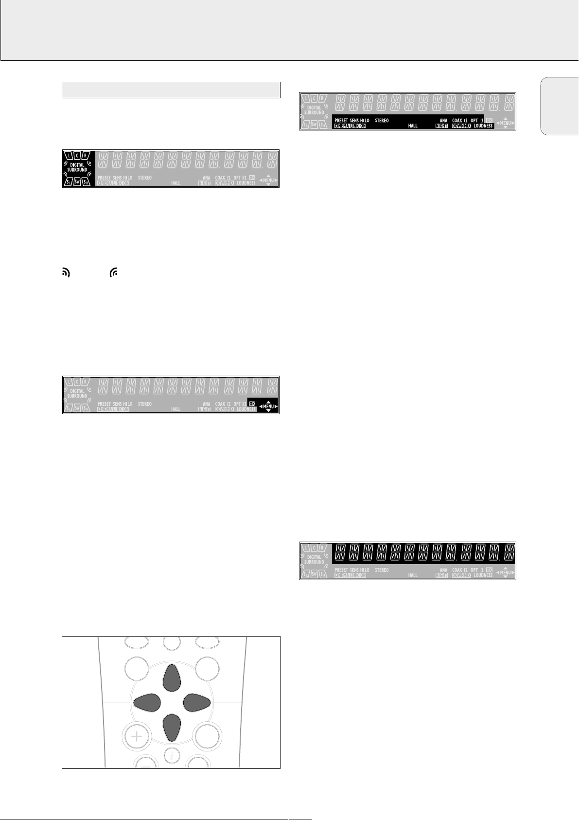
DISPLAY
The display of the receiver is divided into 4 sections, which
are to be used for the following:
Speaker diagram
A rectangle with a letter in it shows that a speaker has been
selected in the setup menu. However, the subwoofer indicator
will only light when a subwoofer signal is available. If only a
letter is shown, this speaker is not used and its sound is
being reproduced by the other speakers.
.....virtual surround sound
SURROUND.................surround sound is reproduced
DIGITAL SURROUND ....digital surround sound is reproduced
L, R ...........................front left and right speaker
C...............................center speaker
SL, SR .......................surround speakers
SW............................subwoofer
Menu indication
These signs show you if the menu is on or off and indicate in
which direction you may move.
MMEENNUU .......................Menu is on.
1..............................You may move backwards to the previous
menu topic using 1 PREV. / EXIT (“left”
key on the remote control).
3 .............................You may move up in an option list using
X MENU NAVIGATOR (“up” key on the
remote control).
4 .............................You may move down in an option list
using X MENU NAVIGATOR (“down” key
on the remote control).
2..............................You may move forward to the next menu
topic using NEXT 2 (“right” key on the
remote control).
OOKK.............................You may confirm the displayed value.
Status lights
Signs showing you various settings and information about the
status of the receiver.
PRESET......................Tuner is tuned to a preset radio station.
SENS HI.....................Tuner is switched to high sensitivity.
SENS LO..................Tuner is switched to low sensitivity.
CCIINNEEMMAA LLIINNKK OONN ......CINEMA LINK is active
STEREO......................An FMstation is being received in stereo.
SMART SOUND...........One of the preset sound settings of
the receiver is being used (FR 965, FR 968
only).
HALL..........................HALL effect is on.
ANA ..........................Analog input is being used for the playing
source.
NNIIGGHHTT.......................NIGHT MODE is on.
COAX
1
......................Coaxial digital input COAX 1 is being
used for the playing source.
COAX
2
.....................Coaxial digital input COAX 2 is being
used for the playing source.
DDOOWWNNMMIIXX.................Incoming multichannel signals are being
reduced to fewer output signals
(depending on the number of speakers).
OPT...........................Optical digital input OPTICAL IN is being
used for the playing source (FR 965,
FR 968 only).
OPT
1
........................Optical digital input OPTICAL 1 IN
is being used for the playing source
(FR 975 only).
OPT
2
.......................Optical digital input OPTICAL 2 IN
is being used for the playing source
(FR 975 only).
LOUDNESS .................LOUDNESS is switched on.
Information area
This area is used for feedback of the receiver, tuner
frequencies, menu options, values and scrolling text
messages.
0
Display
ON/OFF
GUIDE
MENU
OK
É
AA
TV
Page 18

18
English
MENUS
The receiver is equipped with a menu system. The menu is
used for the setup of the receiver. The different menu options
are related to each other in a logical way. Let’s assume you
have no center speaker connected, and so you switched
CENTER SPEAKR to NO. If you try to use VOL CENTER,
a message will be scrolled that this is not possible
(INSTALL CENTER SPEAKER).
The menu always works the same way. Arrows in the display
show you the possible moving directions.
1 Press SETUP MENU.
yMENU, and * EFFECTS is displayed.
• You can exit the menu at any time by pressing
SETUP MENU.
2 Turn X MENU NAVIGATOR until the desired option (or a
value) is displayed.
3 Press NEXT 2 to choose the displayed option (or
ENTER / OK to confirm a value).
• You can leave any option (values remain unchanged) by
pressing 1 PREV. / EXIT.
Menu structure
* EFFECTS
Switches sound effects.
3D SURR (FR 965, FR 968 only)
virtual 3D surround: 0…100 %
VIRT SURR (FR 975 only)
virtual surround: 0…100 %
* VOL BALANCE
Adjusts the relative volume balance between the
connected speakers.
TEST TONE
Test tone: on/off
VOL FRONT-L
Volume front left speaker: –50…+50
VOL FRONT-R
Volume front right speaker: –50…+50
VOL CENTER
Volume center speaker: –50…+50
VOL REAR-L
Volume rear left speaker: –50…+50
VOL REAR-R
Volume rear right speaker: –50…+50
VOL SUBWOOFER
Volume subwoofer: –50…+50
Note: When using the 6 CHANNEL / DVD INPUT the values
below cannot be changed.
* SPEAKR SETUP
Selects the used speakers.
SUBW PRESENT
Subwoofer present: yes/no
CENTER SPEAKR
Center speaker present: yes/no
REAR SPEAKER
Rear speakers present: yes/no
* SPEAKR SIZES
Chooses the speaker sizes of the used speakers, for
optimal sound reproduction. LARGE indicates a speaker
which can reproduce frequencies lower than 50 Hz. If
SUBW PRESENT is set to NO, FRONT SIZE can only
be set to LARGE. If FRONT SIZE is set to SMALL,
CENTER SIZE can only be set to SMALL and
consequently a subwoofer must be connected.
SUBW PRESENT (FR 965, FR 968 only)
Subwoofer present: yes/no
FRONT SIZE
Left and right front speakers: small/large
CENTER SIZE
Center speaker: small/large
REAR SIZE
Rear speakers: small/large
* SPK DISTANCE
Distance between the usual listening position and the
speakers. This defines the delay time for the surround sound.
DISTANCE L/R
Distance to front speakers: 1…10 m (3…30 ft)
DISTANCE CNTR
Distance to center speaker: 1…10 m (3…30 ft)
DISTANCE REAR
Distance to rear speakers: 1…10 m (3…30 ft)
Receiver menu
Page 19

19
English
MENUS
* SELECT INPUT
Assigns the audio input connectors to the different source
selections chosen with SOURCE SELECTOR (see “Source
selection” for details).
COAX1
Digital coaxial input 1, COAX 1 IN
COAX2
Digital coaxial input 2, COAX 2 IN
OPT (FR 965, FR 968 only)
Digital optical input, OPTICAL IN
OPT 1 (FR 975 only)
Digital optical input, OPTICAL 1 IN
OPT 2 (FR 975 only)
Digital optical input, OPTICAL 2 IN
SAT IN
Analog audio input SAT IN
VCR IN
Analog audio input VCR IN
TV IN
Analog audio input TV IN
CDR IN
Analog audio input CDR IN
CD IN
Analog audio input CD IN
6 CH IN
Analog audio input 6 CHANNEL / DVD INPUT
* TUNER
Setup for preset radio stations (see “TUNER” for details).
AUTO INSTALL
Stores radio stations automatically
MAN INSTALL
Stores radio stations manually
GIVE NAME
Allows you to assign names to stored radio stations
RESHUFFLE
Resorts stored radio stations
If the receiver is connected to a Philips CINEMA LINK TV via
the CINEMA LINK system control bus jacks (see
“CONNECTIONS”), you may use the TV to set up the system.
An option called RECEIVER will be added to the TV menu.
If CINEMA LINK is on, adjustments on the receiver will be
shown on the TV screen for a few seconds. Consult the
instruction booklet of your TV on how to use the TV menu.
The options offered may vary by TV model.
Switching the connection
• Press CINEMA LINK on or off to switch the connection
between the receiver and the TV.
yIf the connection is switched on, CINEMA LINK ON is
displayed.
Note: We recommend switching CINEMALINK off during
recording. This avoids unwanted interruptions due to
switching TV functions.
If CINEMA LINK is switched on and the TV menu is active,
TV MENU is displayed and the menu and sound functions on
the receiver are locked.
TV menu
Page 20

20
English
SOURCE SELECTION
When selecting a source by turning SOURCE SELECTOR, the
audio and video inputs with the corresponding name are
activated. The incoming signal is reproduced by all audio and
– if the source includes a video signal – video outputs of the
receiver. It is possible to reassign a source selection to other
than these standard inputs.
Source selected........Connectors used
DVD...............................COAX 1 digital audio input and
DVD IN video input
PHONO..........................PHONO IN audio input
TUNER..........................The tuner part of the receiver is used,
all inputs are switched off.
CD.................................CD IN audio input
CDR/TAPE .....................CDR/TAPE IN audio input
TV..................................TV IN audio input and
no video input
VCR...............................VCR IN audio input and
VCR IN video input
SAT ...............................SAT IN audio input and
SAT IN video input
The 6 CHANNEL / DVD INPUT connectors can be assigned to
any of the available sources (excluding TUNER and PHONO).
The assignment can be done via the * SELECT INPUT
option in the menu. See below for more details.
If a source is selected with SOURCE SELECTOR the standard
audio input is used. To change this, the source selection must
be reassigned to another audio input.
Example: Reassigning CD from the analog CD IN audio input
to the digital COAX 2 IN audio input.
1 Choose * SELECT INPUT from the menu and press
NEXT 2.
2 Turn SOURCESELECTOR to select the source which should
be reassigned (e. g. CD).
yThe name of the source is displayed and the light of the
source flashes.
3 Turn X MENU NAVIGATOR to select the input connectors
which should be used (e. g. CD -> COAX2).
4 Press ENTER / OK to confirm your selection.
ySTORED is displayed briefly.
5 This source selection is now using the chosen audio input
(e. g. CD uses the COAX 2 IN input connectors, COAX 2
lights when switching to CD).
You may assign more than one source to a source selection.
This can be useful when products are connected one after the
other in a chain.
Example: A VCR is connected to the TV but only the TV is
connected to the receiver. Both SOURCE SELECTOR
settings, TV as well as VCR, have to use the TV
input connectors.
1 Choose * SELECT INPUT from the menu and press
NEXT 2.
2 Turn SOURCESELECTOR to select the source which should
be reassigned (e. g. VCR).
yThe name of the source is displayed and the light of the
source flashes.
3 Turn X MENU NAVIGATOR to select the input connectors
which should be used (e. g. VCR -> TV IN).
4 Press ENTER / OK to confirm your selection.
ySTORED is displayed briefly.
5 This source selection is now using the chosen audio input (e.
g. VCR uses the TV IN input connectors, VCR <TV IN> is
displayed briefly when switching to VCR).
The 6 CHANNEL / DVD INPUT can be used to connect a
device with a built-in multichannel decoder (e.g. Dolby Digital,
DTS, etc.) and 6-channel output connector, i. e. a high end
DVD player.
When using the 6 CHANNEL / DVD INPUT audio input, the
receiver works as a multichannel amplifier. The source
reproduces surround sound and sends it to the receiver
divided into the necessary channels. Therefore the
SURROUND ON/OFF, HALL and SURR. MODE button have no
effect since the provided signal is already multichannel.
From a source which is connected to the
6 CHANNEL / DVD INPUT audio input cannot be recorded.
About 6 CHANNEL / DVD INPUT
Using one source selection for two or more
appliances
Reassigning a source selection
6 CHANNEL / DVD INPUT selection
SOURCE SELECTOR
Page 21

21
English
PLAYBACK, RECORDING
1 Press POWER / STANDBY to switch on the receiver.
2 Turn SOURCESELECTOR to select a source.
yThe name of the source is displayed.
• You can select the FRONT AV/GAME input by pressing
FRONT AV (FR 975 only).
3 Start playback of the source as usual.
• Turn VOLUME to adjust the volume.
yVOLUME and the volume level between 0 and 50 is
displayed.
1 Press BASS or TREBLE.
yBASS or TREBLE and the actual value are displayed
briefly. Then TURN VOLUME KNOB TO CHANGE is
scrolled.
2 Turn VOLUME to adjust the bass or treble.
yBASS or TREBLE and the actual value are displayed.
Note: If VOLUME is not turned within 5 seconds or if any
other control is used, the bass or treble adjustment is
switched off.
FR 965, FR 968 only:
• Press ±SOUND on the remote control to scroll through
the built-in smart sounds: MOVIE, SPEECH, MUSIC,
MULTIMEDIA and PERSONAL. (PERSONAL is the
userdefined bass and treble setting.)
ySMART SOUND is displayed and the name of the chosen
sound profile is scrolled once if smart sound is on.
FR 975 only:
• If a subwoofer is connected, press SUBW.ON/OFF to
increase the bass performance.
Note: In case of digital surround sound, a subwoofer signal
will only be available when supported by the source
material.
• Press LOUDNESS to switch on or off loudness.
yLOUDNESS is displayed if loudness is on.
If you wish to record from a source you must select it with
SOURCE SELECTOR. The incoming signal is reproduced by all
audio and – if the source includes a video signal – video
outputs of the receiver. The sound settings do not affect the
recording.
1 Turn SOURCESELECTOR (or press FRONT AV, FR 975 only)
to select the source you want to record from.
yThe name of the source is displayed.
2 Prepare the desired recording appliance. It must be
connected to one of the outputs of the receiver.
3 Start recording on the recording appliance.
4 Start the playback of the source as usual.
Note: – The audio and video signal of VCR IN is not
reproduced by VCR OUT. The same applies to the
audio signal of CDR/TAPE IN to CDR/TAPE OUT.
– We recommend not to use the digital output
COAX OUT of the receiver to record from an analog
source. Use the analog output CDR/TAPEinstead.
– From a source which is connected to the
6 CHANNEL / DVD INPUT audio input cannot be
recorded.
It is possible to connect a digital recorder to the digital output of
the receiver. In this way, all signals coming from the digital
inputs can be recorded directly on the connected audio recorder.
The receiver will also convert all signals coming from the analog
inputs to the digital output.
The receiver can be used to record digitally a multichannel
surround sound audio signal (Dolby Digital or DTS) from, for
example, DVD to CD-R. The receiver will convert the digital
multichannel signal into a stereo signal without loss of relevant
sound information.
Notes: – Do not use the 3D SURROUND feature while making
digital recordings as this will distort the digital
audio signal (FR 965, FR 968 only).
– When recording a Dolby Digital or DTS signal, each
track must be recorded individually.
– Digital recording is not possible when the digital
source material is copy-protected.
Recording from the digital output
Recording from a source
Adjusting the sound
Playing a source
Page 22

22
English
SURROUND SOUND
Surround sound gives you a completely new listening
sensation. You will have the feeling of being in the middle of
the action, because sound is coming from everywhere around
you. Look out for TV broadcasts, audio and video tapes and
discs with the 3, 1 or marks which are
encoded for multichannel surround sound. You should prefer
Dolby Digital or DTS to get the most out of your receiver.
The FR 975 is able to reproduce DTS surround sound. DTS is a
premium multichannel surround sound system available on
DVD discs, laserdiscs and audio discs. Consult your software
dealer on the availability of DTS software in your region.
Notice that DVD discs do not always carry full multichannel
surround. To be sure that a disc is multichannel encoded
consult your dealer.
Most ordinary stereo tapes and discs can be replayed using
surround sound settings with good results. If the reproduction
is distorted in surround mode, switch to normal stereo mode.
The availabilty of the various surround sound modes
described depends on the number of speakers used and the
incoming sound information.
With surround sound on, you can switch through the different
surround modes. Note that the possibilities are related to
speaker setup defined in the receivers menu.
If a digital surround signal is detected, the receiver will scroll
either DOLBY DIGITAL or DTS.
1 Press SURROUND ON/OFF to switch on the surround sound.
yThe surround mode in use is scrolled.
2 Press SURR. MODE repeatedly to listen to the different
surround modes (if available).
yThe chosen mode and the speakers used are displayed.
If the incoming multichannel signals are reduced to
fewer output signals, DOWNMIX is displayed.
FR 965, FR 968 only:
3 Press 3D SURROUND to switch on or off virtual 3D surround.
yA light indicates if virtual 3D surround is on.
FR 975 only:
3 Press VIRTUAL MODE as often as necessary to switch
through the virtual surround sound modes:
1 × to activate 3D SURROUND
2 × to activate MULTI FRONT
3 × to activate MULTI REAR
4 × to activate NATURAL SURROUND
yA light indicates if a virtual surround sound mode is on.
-signs indicate which virtual surround sound mode is
active.
4 Press SURROUND ON/OFF to switch off the surround
sound.
ySURROUND OFF is scrolled.
Switching surround sound
About surround sound
Page 23
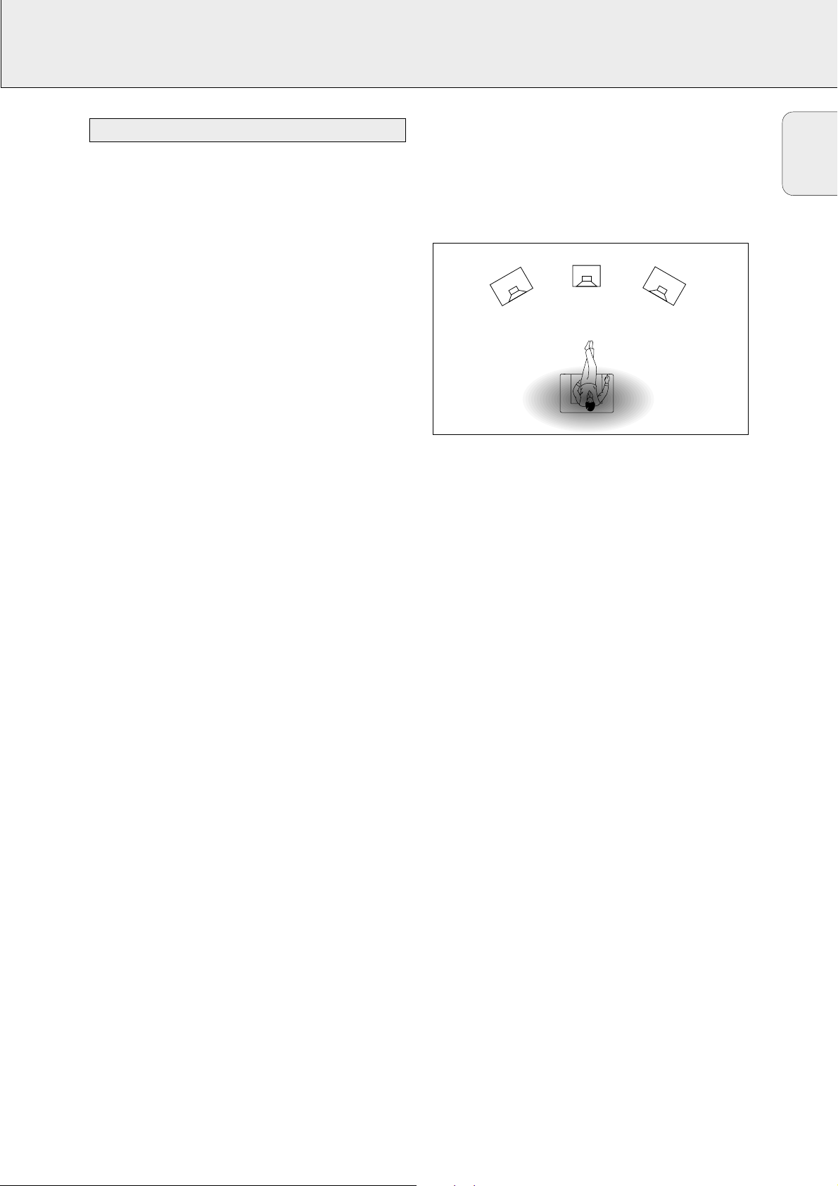
23
English
SURROUND SOUND
HALL
The sound reproduction is enhanced and a slight echo is
added. This gives the impression of being in a large room.
Can only be used in stereo mode.
SURROUND
The surround mode enables normal surround sound
reproduction with 4 or 5 speakers. Depending on the source
material, Dolby Surround Pro Logic, Dolby Digital or DTS is
reproduced.
PRO LOGIC, DOLBY DIGITAL, DTS
In addition to SURROUND, the surround mode used –
depending on the source material – will be displayed. In case
of digital surround, the sound format AC-3 (for Dolby Digital) or
DTS will be displayed, followed by the sound channels, available
on the source (e. g. DVD).
Example: AC-3 3/2.1 Dolby Digital, 3 front channels,
2 surround channels and a
subwoofer channel.
AC-3 3/1.0 Dolby Digital, 3 front channels,
1 (mono) surround channel without
subwoofer signal.
DTS 3/2.1 DTS, 3 front channels, 2 surround
channels and a subwoofer channel.
FRONT-3 STEREO
The surround sound is muted. 3 Stereo lets you listen to
surround sound without using the surround speakers.
STEREO
All sound is reproduced and played through the front left and
right speakers. This enables standard stereo reproduction.
Virtual Surround
Your receiver is able to reproduce one or more forms of virtual
surround sound. Virtual surround gives a more real life sound
impression by creating phantom speakers in addition to or
instead of real speakers. The position of the listener
influences the surround effect. The area where the effect is
best is shown in grey.
The level of virtual surround sound effect can be adjusted in
the setup menu. The following surround sound modes are
available:
3D SURROUND
No rear speakers are needed. The sound of the rear channel
is simulated by the front speakers. Surround sound is
simulated through the front left, right and center speakers.
MULTI FRONT (FR 975 only)
Phantom speakers are created next to the left and right front
speaker.
MULTI REAR (FR 975 only)
Phantom speakers are created next to the left and right rear
speaker.
NATURAL SURROUND (FR 975 only)
Phantom speakers are created next to the left and right front
and rear speakers.
Note: The availability of MULTI FRONT and
MULTI REAR depends on the sound channels on the
source material (FR 975 only).
NIGHT MODE (only on the remote control)
The loud parts of the sound are lowered and the soft passages
are raised. You can enjoy surround sound without disturbing
sleeping children or neighbors. Night mode only works with
Dolby Digital, and only if supported by the source material.
Surround sound settings
CENTER
FRONT
FRONT
LEFT
RIGHT
Page 24

24
English
TUNER
You can search for radio stations by scanning the frequency
band. You can also key in the frequency of a known radio
station. If an FM station is being broadcast and received in
stereo, STEREO is shown.
Searching for radio stations
1 Turn SOURCESELECTOR to select the tuner.
yTUNER is displayed.
2 Select a waveband by pressing TUNER BAND repeatedly.
yThe selected waveband is displayed.
3 Keep 1 or 2 pressed for approximately 1 second.
ySEARCH is displayed and the tuner tunes to a station
with sufficient strength.
4 Repeat this procedure until you find the desired station.
• To fine tune to a weak transmitter, briefly press 1 or 2 as
often as necessary for optimum reception.
Tuning to a radio station by frequency (with the remote
control only)
1 Press TUNER.
yTUNER is displayed.
2 Press FR. D..
y_ is displayed.
3 Use 1–0 to key in the frequency of a radio station.
Notes: Only valid numbers within the frequency range of the
tuner can be keyed in.
You can switch the tuner to a lower search sensitivity, to
search only for stations with a strong signal (FM only).
1 Turn SOURCESELECTOR to select the tuner.
yTUNER is displayed.
2 Press SENS. on the receiver.
yEither SENS HI or SENS LO is displayed for 5 seconds.
Note: While searching for radio stations, the actual sensitivity
is displayed. In this case, SENS LO means the tuner is
looking only for radio stations with a strong signal.
You may store up to 30 radio stations in the memory. The
receiver can select and program radio stations by itself or you
can choose them yourself.
Automatic programming
1 Choose * TUNER from the menu and press NEXT 2.
2 Choose AUTO INSTALL and press NEXT 2.
yThe preset number where programming will start, the
waveband and AUTO are displayed.
3 Turn TUNERPRESET X to change the preset number where
programming should start.
4 Use TUNER BAND to switch to the desired waveband.
5 Press ENTER / OK to start programming.
yAUTO INSTALL flashes and all available radio
stations are programmed, this may take a few minutes.
Programming is done when AUTO INSTALL stops
flashing.
Manual programming
1 Choose * TUNER from the menu and press NEXT 2.
2 Choose MAN INSTALL and press NEXT 2.
yA preset number, the waveband and the frequency are
displayed.
3 Turn TUNERPRESET X to change to the preset number
where the radio station should be stored.
4 Tune to the desired radio station (see “Searching for radio
stations”).
5 Press ENTER / OK to confirm your selection.
ySTORED is displayed briefly. The radio station is
programmed at the chosen preset number.
6 Select and store all desired radio stations this way.
Storing radio stations
Switching FM sensitivity
Tuning to radio stations
Page 25

25
English
TUNER
1 Turn SOURCESELECTOR to TUNER to select the tuner.
yTUNER is displayed.
2 Turn TUNERPRESET X to select a preset radio station.
yPRESET, the preset number and station are displayed.
After programming radio stations, you might want to change
their sequence. RESHUFFLE allows you to exchange the
positions of presets.
1 Choose * TUNER from the menu and press NEXT 2.
2 Choose RESHUFFLE and press NEXT 2.
yPRESET, a preset number and station are displayed.
3 Turn TUNERPRESET X to select a preset station.
4 Press ENTER / OK to confirm the selection.
yThe selected preset number SWAP <-> and a second
preset number are displayed.
5 Turn TUNERPRESET X to select the other preset station.
6 Press ENTER / OK to confirm the exchange.
yRESHUFFLED is displayed briefly and these two
preset numbers are swapped.
It is possible to assign a name to any of the preset radio
stations.
1 Choose * TUNER from the menu and press NEXT 2.
2 Choose GIVE NAME and press NEXT 2.
yA preset radio station is displayed.
3 Turn TUNERPRESET X to select the preset to be renamed.
4 Press ENTER / OK to confirm your selection.
yThe existing name or ________ is displayed.
5 Turn TUNERPRESET X to select a letter and NEXT 2 or
1 PREV. to move to the next or previous position.
6 After you have entered the entire name, press ENTER / OK
to confirm.
ySTORED is displayed and the name is stored.
1 Use the menu option * TUNER, choose GIVE NAME.
yA preset radio station is displayed.
2 Turn X MENU NAVIGATORto select the name to be
cleared.
3 Press ENTER / OK to confirm your selection.
4 Press 1 PREV. while the first letter is flashing.
y CL is flashing to the left of the station name.
5 Press ENTER / OK to clear the station name.
Or, if you have changed your mind,
press 1 PREV. to leave the station name as it is.
Clearing station names
Naming radio stations
Resorting stored radio stations
Tuning to stored radio stations
Page 26

26
English
TECHNICAL DATA
Subject to modification without notice.
General
Power consumption (FR 965)...........................................260 W
Power consumption (FR 968, FR 975)..............................280 W
Standby power consumption............................................< 2 W
Dimensions, w × h × d ............................435 × 135 × 350 mm
Weight (FR 965)................................................................8.6 kg
Weight (FR 968, FR 975)...................................................9.4 kg
Amplifier part (0.7 % THD, 6 Ω)
FR 965:
Output power, stereo mode: FTC (40 Hz–20 kHz).......2 × 50 W
Output power, surround mode (1 kHz)
Front......................................................................2 × 60 W
Center..........................................................................60 W
Surround................................................................2 × 60 W
FR 968, FR 975:
Output power, stereo mode: FTC (40 Hz–20 kHz).......2 × 80 W
Output power, surround mode (1 kHz)
Front....................................................................2 × 100 W
Center........................................................................100 W
Surround..............................................................2 × 100 W
Bass..................................................................±9 dB at 100 Hz
Treble ................................................................±9 dB at 10 kHz
Loudness....+6 dB at 100 Hz (-30 dB); +3 dB at 10 kHz (-30 dB)
Total harmonic distortion.........................0.05 % at 1 kHz, 5 W
Frequency response..................................20–20,000 Hz, ±1 dB
S/N ratio........................................................................≥ 82 dB
Stereo separation (1 kHz)..............................................≥ 45 dB
Crosstalk (1 kHz)...........................................................≤ -65 dB
Inputs
Linear inputs.......................................................250 mV/47 kΩ
6 CH ....................................................................250 mV/40 kΩ
Front AV (FR 975 only)........................................250 mV/22 kΩ
Phono......................................................................5 mV/47 kΩ
Digital coaxial ..............................................75 Ω acc. IEC 958
Digital optical...................................................................toslink
Outputs
Power supply AC outlets (switched)...........totally max. 120 W
Linear outputs .......................................................250 mV/1 kΩ
Digital coaxial ..............................................75 Ω acc. IEC 958
Digital output sampling frequencies
Analog in.............................................................out 48 kHz
Digital in 32 kHz..................................................out 32 kHz
Digital in 44.1 kHz............................................out 44.1 kHz
Digital in 48 kHz..................................................out 48 kHz
Digital in 96 kHz (FR 975 only)............................out 48 kHz
Subwoofer pre-out....................................................0.8 V/1 kΩ
Center pre-out...........................................................0.8 V/1 kΩ
Headphones....................................8–600 Ω (3 V e.m.f., 60 Ω)
Speakers...........................................................................≥ 6 Ω
Tuner part
Wave range
FM..............................................................87.5–108.0 MHz
AM................................................................530–1,700 kHz
Sensitivity
Stereo FM..................................................................41 dBf
Mono FM....................................................................17 dBf
Total harmonic distortion
Stereo FM...................................................................0.8 %
Mono FM.....................................................................0.9 %
Frequency response...................................63–12,500 Hz ±1 dB
S/N ratio
Stereo FM....................................................................55 dB
Mono FM .....................................................................60 dB
Channel separation.............................................27 dB at 1 kHz
Receiver
Page 27

TECHNICAL DATA
27
Subject to modification without notice.
Front speakers
System................................................................2-way shielded
Impedance........................................................................6–8 Ω
Speaker drivers.........................................3" fullrange, 1" piezo
Dimensions, w × h × d ................................94 × 155 × 88 mm
3.8 × 6.2 × 3.5 inches
Weight...............................................................0.45 kg, 0.98 lb
Center speaker
System................................................................2-way shielded
Impedance........................................................................6–8 Ω
Speaker drivers..................................2 × 3" fullrange, 1" piezo
Dimensions, w × h × d ................................250 × 94 × 88 mm
10 × 3.8 × 3.5 inches
Weight...............................................................0.92 kg, 2.03 lb
Surround speakers
System.................................................................2-way satelite
Impedance........................................................................6–8 Ω
Speaker drivers.........................................3" fullrange, 1" piezo
Dimensions, w × h × d ................................94 × 155 × 88 mm
3.8 × 6.2 × 3.5 inches
Weight...............................................................0.45 kg, 0.98 lb
Active subwoofer SW090, SW990
– not magnetically shielded design
Subwoofer............................................................................6.5"
Output power..........................................50 W RMS (4 Ω, DIN)
THD.......................................................................10% at 55 Hz
Reproduction frequency response .......................45 Hz–110 Hz
Phase switch.................................................................0°, 180°
Input sensitivity (subwoofer in)................................460 mVrms
AC power................................................................120 V/60 Hz
Power consumption.............................70 W (at
1
⁄
8 rated power)
Dimensions, w × h × d ............................200 × 310 × 370 mm
7.87 × 12.20 × 14.57 inches
Weight..........................................................15.40 pounds, 7 kg
Active subwoofer with wOOx technology SW965, SW966
– not magnetically shielded design
Subwoofer............................................................................6.5"
Output power..........................................50 W RMS (4 Ω, DIN)
THD.....................................................................10% at 100 Hz
Reproduction frequency response .......................30 Hz–110 Hz
Phase switch.................................................................0°, 180°
Input sensitivity (subwoofer in)................................200 mVrms
AC power................................................................120 V/60 Hz
Power consumption.............................40 W (at
1
⁄
8 rated power)
Dimensions, w × h × d ............................200 × 310 × 370 mm
7.87 × 12.20 × 14.57 inches
Weight............................................................15 pounds, 6.8 kg
Active subwoofer with wOOx technology SW985, SW986
– not magnetically shielded design
Subwoofer............................................................................6.5"
Output power........................................100 W RMS (4 Ω, DIN)
THD.....................................................................10% at 100 Hz
Reproduction frequency response .......................30 Hz–110 Hz
Phase switch.................................................................0°, 180°
Input sensitivity (subwoofer in)................................200 mVrms
AC power................................................................120 V/60 Hz
Power consumption.............................52 W (at 1⁄8 rated power)
Dimensions, w × h × d ............................200 × 310 × 370 mm
7.87 × 12.20 × 14.57 inches
Weight.........................................................18.5 pounds, 8.4 kg
Speakers (supplied with MX packages only)
English
Page 28

28
English
TROUBLESHOOTING
PROBLEM POSSIBLE CAUSE SOLUTION
No sound VOLUME is not adjusted correctly. Adjust the VOLUME.
Headphones are connected. Disconnect headphones.
The wrong source is selected. Turn SOURCE SELECTOR to select the correct
source.
No sound on the One speaker is connected incorrectly. Connect the speaker properly.
left or right side
A speaker cable is damaged. Replace the cable.
Volume balance in the receiver menu is Adjust VOL FRONT-L and VOL FRONT-R
adjusted incorrectly. in the receiver menu.
Poor sound or no sound at SURROUND mode is not switched on. Press SURROUND ON/OFFto switch on the
the center or surround surround sound.
speakers
Surround and/or center speakers are not Connect the speakers properly.
(properly) connected.
Surround and/or center speakers are switched Set speaker present to YES.
off in the SPEAKR SETUP menu.
A speaker cable is damaged. Replace the cable.
Poor bass sound Speakers are not in phase. Connect the colored (or marked) wires to the
colored terminals and the black (or unmarked)
wires to the black terminals.
Bad sound Badly matching setting for the given type of Correct the sound settings on the receiver.
music or sound.
Surround sound level is The level of the surround sound is not Adjust the level of the surround sound on
too low or too high adjusted properly. the receiver.
Center sound level is too The sound level of the center channel is not Adjust the level of the center channel
low or too high adjusted properly . on the receiver.
Only center speaker is A mono signal is reproduced. Choose a different sound source or switch off
heard in Dolby Surround surround sound.
Pro Logic
Bad radio reception, Receiver or antenna is positioned near a Change the position of the interfering unit
automatic programming radiation source such as TV, CD player, or try to switch it off.
does not work properly CD recorder, DVD player, etc.
No digital recording The sampling frequency is not accepted by Make sure the digital recorder can handle
possible via digital output the digital recorder. sampling frequencies between 32 kHz and 48 kHz
or make the recording via analog output.
Whole recording appears The DVD player does not provide track Record each track individually or use the
as one track when information. “manual track increment” feature on the recorder.
recording from DVD disc
WARNING
Under no circumstances should you try to repair the
set yourself as this will invalidate the warranty. Do
not open the set as there is a risk of electric shock.
If a fault occurs, first check the points listed, before taking
the set for repair.
If you are unable to solve a problem by following these hints,
consult your dealer or service centre.
Page 29

AUDIO SYSTEM
One Year Free Labor
One Year Free Service on Parts
This product must be carried in for repair.
LIMITED W ARRANTY
WHO IS COVERED?
You must have proof of purchase to receive warranty service .A sales
receipt or other document showing that you purchased the product
is considered proof of purchase.
WHAT IS COVERED?
Warranty coverage begins the day you buy your product. For one
year thereafter,all par ts will be repaired or replaced,and labor is
free.After one year from the day of purchase, you pay for the
replacement or repair of all parts,and for all labor charges.
All parts, including repaired and replaced parts,are covered only for
the original warranty period.When the warranty on the product
expires,the warranty on all replaced and repaired parts also expires.
WHAT IS EXCLUDED?
Your warranty does not cover:
• labor charges for installation or setup of the product,adjustment
of customer controls on the product,and installation or repair of
antenna systems outside of the product.
• product repair and/or part replacement because of misuse, accident,unauthorized repair or other cause not within the control of
Philips Consumer Electronics Company.
• reception problems caused by signal conditions or cable or antenna systems outside the unit.
• a product that requires modification or adaptation to enable it to
operate in any country other than the country for which it was
designed,manufactured,approved and/or authorized,or repair of
products damaged by these modifications.
• incidental or consequential damages resulting from the product.
(Some states do not allow the exclusion of incidental or consequential damages,so the above exclusion may not apply to you.
This includes,but is not limited to,prerecorded material,whether
copyrighted or not copyrighted.)
• a product that is used for commercial or institutional purposes.
WHERE IS SERVICE AVAILABLE?
Warranty service is available in all countries where the product is
officially distributed by Philips Consumer Electronics Company.In
countries where Philips Consumer Electronics Company does not
distribute the product,the local Philips service organization will
attempt to provide service (although there may be a delay if the
appropriate spare parts and technical manual(s) are not readily available).
MAKE SURE YOU KEEP...
Please keep your sales receipt or other document showing proof of
purchase. Attach it to this owner’s manual and keep both nearby.Also
keep the original box and packing material in case you need to return
your product.
BEFORE REQUESTING SERVICE...
Please check your owner’s manual before requesting service.
Adjustments of the controls discussed there may save you a service
call.
TO GET WARRANTY SERVICE IN U.S.A.,
PUERTO RICO OR U.S. VIRGIN ISLANDS...
Take the product to a Philips factory service center (see enclosed
list) or authorized service center for repair. When the product has
been repaired,you must pick up the unit at the center.Centers may
keep defective parts.(In U.S.A., Puer to Rico and U.S. Virgin Islands, all
implied warranties,including implied warranties of merchantability
and fitness for a particular purpose, are limited in duration to the
duration of this express warranty.But, because some states do not
allow limitations on how long an implied warranty may last,this limitation may not apply to you.)
TO GET WARRANTY SERVICE IN CANADA...
Please contact Philips at:
1-800-661-6162 (French Speaking)
1-800-363-7278 (English Speaking)
(In Canada,this warranty is given in lieu of all other warranties.No
other warranties are expressed or implied,including any implied warranties of merchantability or fitness for a particular purpose.Philips is
not liable under any circumstances for any direct, indirect, special,
incidental or consequential damages,howsoever incurred,even if
notified of the possibility of such damages.)
REMEMBER...
Please record the model and serial numbers found on the product
below.Also,please fill out and mail your warranty registration card
promptly.It will be easier for us to notify you if necessary.
MODEL # ________________________________________
SERIAL # ________________________________________
EL4965E005 / MAC 4110 / 1-97
This warranty gives you specific legal rights.You may have other rights which vary from state/province to state/province.
Philips Service Solutions Group,P.O.Box 2976,Longview, Texas 75606, (903) 242-4800
Page 30

Connaissez ces
symboles de
ssééccuurriittee
t
Cet « éclair à pointe de flèche »
indique qu’un matériau non isolé,
situé à l’intérieur de l’unité,risque
de provoquer un choc électrique.Pour la
sécurité de chacun,nous vous prions de ne pas
retirer le boîtier de ce produit.
s
Le « point d’exclamation » attire
votre attention sur des sujets
risquant de provoquer des
problèmes de fonctionnement et d’entretien si
vous ne lisez pas les informations s’y reportant.
D ANGER:NE PAS EXPOSER CET
ÉQUIPEMENT A LA PLUIE NI A UNE HUMIDITÉ
EXCESSIVE POUR ÉVITER LES RISQUES
D’INCENDIE ET DE CHOC ÉLECTRIQUE.
ATTENTION: Pour éviter les chocs
électriques,introduire la lame la plus large de
la fiche dans la borne correspondante de la
prise et pousser jusqu’au fond.
Cet espace vous est réservé
Inscrivez ci-dessous le numéro de série situé à
l’arrière du bloc.Conservez cette information
pour vous y reporter à l’avenir.
N° de modèle ________________________
N° de série __________________________
• Dès que l’achat de votre appareil Philips est enregistré,
vous avez droit à tous les avantages dont bénéficient les
possesseurs des produits Philips.
• Remplissez et renvoyez votre carte d’enregistrement de
garantie jointe à votre appareil sans tarder.Vous
bénéficierez de ces avantages importants.
Renvoyez votre carte d’enregistrement de garantie pour vous
assurer de recevoir tous les avantages auxquels vous avez droit.
Vérification
de garantie
Enregistrez votre produit dans les
10 jours pour confirmer votre droit à
une protection maximum selon les
termes et les conditions de votre
garantie Philips.
Confirmation
de possession
Votre carte d’enregistrement de
garantie prouve que vous possédez
l’appareil en cas de vol ou de perte
du produit.
Enregistrement
du modèle
Renvoyez votre carte d’enregistrement
de garantie dès aujourd’hui pour vous
assurer de recevoir toutes les
informations,les offres et les bonus
auxquels vous avez droit en tant que
possesseur de ce modèle.
Vous félicitant de votre achat,
la « famille » vous souhaite la bienvenue!
Cher possesseur de produit Philips,
Nous vous remercions de la confiance dont vous témoignez à Philips. Vous avez
choisi l’un des produits actuellement sur le marché les mieux construits et
bénéficiant d’un des meilleurs service après-vente. Et nous mettrons tout en
oeuvre pour que vous demeuriez satisfait de votre produit au cours des
nombreuses années à venir.
A présent membre de la « famille » Philips, vous êtes protégé par l’une des
garanties les plus complètes et l’un des réseaux de service les plus
exceptionnels de l’industrie.
De plus,grâce à votre achat vous recevrez toutes les informations, offres et
tous les bonus auxquels vous avez droit ainsi qu’un accès facile à notre réseau
d’achat à domicile très pratique.
Et,plus important encore, vous pouvez compter sur notre dévouement
incomparable à vous apporter une satisfaction totale.
Nous vous souhaitons ainsi la bienvenue tout en vous remerciant d’avoir investi
dans un produit Philips.
Sincèrement,
Robert Minkhorst
Président Directeur général
P.S. N’oubliez pas de renvoyer votre carte d’enregistrement de
garantie dans les 10 jours pour obtenir le maximum de votre
produit Philips.Veuillez donc la renvoyer dès maintenant!
sur le World Wide Web est: http://www.philipsusa.comL‘adresse de
MAC5097
E
R
T
S
I
G
E
R
N
E
•
S
R
Vite!
U
O
J
0
1
S
E
L
M
E
N
T
N
E
C
E
S
S
A
I
R
E
D
A
N
S
ATTENTION: POUR REDUIRE LE RESQUE DE CHOC ELECTRIQUE, NE PAS ENLEVER
LE COUVERCLE (NI LE PANNEAU ARRIERE). CET APPAREIL NE COMPORTE AUCUNE
PIECE POUVANT TRE REPAREE PAR L’UTILISATEUR. CONFIER SON ENTRETIEN A
ATTENTION
RISQUE DE CHOC ELECTRIQUE
NE PAS OUVRIR
UN TECHNICIEN QUALIFIE.
Page 31

31
Français
Ce produit a été conçu et fabriqué en accord avec des
normes de sécurité et de qualité très strictes. Il existe
toutefois des précautions d'installation et de fonctionnement
qu'il est important de connaître et de respecter.
1. Lisez ces instructions. – Il est impératif de lire toutes
les consignes de sécurité et les instructions de
fonctionnement avant d'utiliser l'appareil.
2. Conservez ces instructions. – Il est recommandé de
conserver ces consignes de sécurité et instructions de
fonctionnement pour référence ultérieure.
3. Respectez les avertissements. – Tous les
avertissements inscrits sur l'appareil lui-même ou
figurant dans les instructions de fonctionnement doivent
être respectés.
4. Suivez toutes les instructions. – Il est impératif de
suivre toutes les instructions de fonctionnement et
d'utilisation.
5. N'utilisez pas cet appareil à proximité d'une
source d'eau – comme par exemple, une baignoire, un
lavabo, un évier de cuisine, un baquet de lingerie, ou
dans une cave humide, près d'une piscine, etc.
6. Nettoyez l'appareil uniquement avec un chiffon
humide. – Cet appareil doit être nettoyé uniquement
selon la procédure recommandée par le fabricant.
7. Installez l'appareil selon les instructions du
fabricant. N'obstruez aucun orifice de ventilation.
– Par exemple, l'appareil ne doit pas être posé sur un
canapé, un lit, un tapis, ou autre surface du même type ;
il ne doit pas non plus être placé dans un meuble intégré
comme un ensemble bibliothèque ou autre où le
système de ventilation de l'appareil serait bloqué.
8. N'installez pas l'appareil près d'une source de
chaleur comme par exemple des radiateurs, bouches de
chaleur, cuisinières, ou autres appareils (même des
amplificateurs) dégageant de la chaleur.
9. Ne détruisez pas la sécurité
incorporée dans la prise de terre
ou prise polarisée fournie
– Une prise polarisée est dotée
de deux lames dont une plus large que l'autre. Une prise
de terre est dotée de deux fiches semblables et d'une
troisième, plus large, qui assure la mise à la terre pour
votre sécurité. Si la prise fournie ne convient pas à la
prise murale dont vous disposez, consultez un électricien
pour remplacer et adapter votre prise murale.
10. Protégez le cordon d'alimentation pour éviter de
marcher dessus ou de le pincer particulièrement aux
endroits des prises, mâles et femelles, et au point de
raccordement sur l'appareil lui-même.
11. Utilisez uniquement des accessoires ou options
recommandés par le fabricant.
12. Utilisez uniquement un meuble sur
roulettes, un support, un pied, une étagère
ou une table de type recommandé par le
fabricant. Si vous utilisez un meuble sur
roulettes, veillez à le déplacer avec
précaution afin d'éviter tout accident
corporel si l'équipement se renversait.
13. Débranchez l'appareil pendant les orages ou s'il doit
rester inutilisé pendant une période de temps prolongée.
14. Pour toute réparation, faites appel à un personnel
qualifié. Une réparation sera nécessaire si l'appareil a
subi des dommages tels que détérioration du cordon
d'alimentation ou de la prise, liquide renversé sur
l'appareil, ou encore si un objet est tombé dessus, si
l'appareil a été exposé à la pluie ou à l'humidité, s'il ne
fonctionne pas correctement ou s'il a fait une chute.
15.
PRÉCAUTION d’emploi des piles – Afin d’éviter
toute fuite des piles qui risquerait de causer des
blessures corporelles ou d’endommager l’appareil :
• Installez toutes les piles correctement, + et - tels
qu’indiqués sur l’appareil.
•
Ne mélangez pas les piles (pas de piles neuves avec des
usagées ou de piles au carbone avec des alcalines, etc.).
• Enlevez les piles lorsque l’appareil reste inutilisé
pendant une longue période.
EL 6475-F001: 00/8
CONSIGNES DE SÉCURITÉ IMPORTANTES– A lire avant toute utilisation du matériel
Prise
polarisée C.A.
Page 32

32
Français
GENERALITES
Cet équipement comprend :
– une télécommande universelle
– 2 piles pour télécommande, type AA
–
un câble coaxial pour les connexions audio avec un lecteur DVD
– un câble coaxial pour la connexion vidéo avec un lecteur DVD
ou un téléviseur
– une antenne-cadre
– une antenne à câble
– 5 enceintes y compris 5 câbles de raccordement (pour les
ensembles MX seulement)
– un subwoofer y compris câble de raccordement et un
cordon secteur (pour les ensembles MX seulement)
–
une carte d‘installation rapide (pour les ensembles MX seulement)
– ce manuel d‘utilisation
Si vous avez empilé les composants de votre système, le
récepteur doit se trouver en haut. Placez le récepteur sur
une surface plane, dure et stable. Ne couvrez aucun
orifice de ventilation et maintenez un encombrement de
50 cm (20 pouces) au-dessus de l‘équipement et de 10 cm
(4 pouces) à gauche et à droite du récepteur pour assurer
une ventilation adéquate.
Pour obtenir une réception optimale, l‘antenne-cadre ne devra pas
être placée au-dessous et sur des VCR, des enregistreurs CD, des
lecteurs DVD, des téléviseurs et d‘autres sources de radiation.
Tous les matériaux d‘emballage superflus ont été supprimés.
Nous avons fait notre possible afin que l‘emballage soit
facilement séparable en trois types de matériaux : carton
(boîte), polystyrène expansible (matériel tampon) et
polyéthylène (sachets, feuille de protection en mousse).
Votre appareil est composé de matériaux pouvant être recyclés
et réutilisés s‘il est démonté par une firme spécialisée.
Veuillez observer les règlements locaux en vigueur sur la
manière de vous débarrasser des anciens matériaux
d‘emballage, des piles usées et de votre ancien appareil.
Fabriqués sous licence des Laboratoires Dolby. «DOLBY »,
« DOLBY DIGITAL», « PRO LOGIC » et le symbole double-D 2
sont des marques déposées des Laboratoires Dolby. Travaux
confidentiels non publiés. © 1992–1997 Dolby Laboratories.
Tous droits réservés.
« DTS » et « DTS Digital Surround » sont des marques
déposées de Digital Systems Inc. Copyright 1996 Theater
Systems, Inc. Tous droits réservés.
Admission des marques déposées
Informations relatives à l‘environnement
Mise en place
Produits livrés avec l‘équipement
Conseils de sécurité
Conseils de sécurité..................................................................30–31
Généralités
Produits livrés avec l‘équipement....................................................32
Mise en place ..................................................................................32
Informations relatives à l‘environnement........................................32
Admission des marques déposées..................................................32
Commandes........................................................................................33
Télécommande
Utilisation de la télécommande.......................................................34
Boutons de la télécommande..........................................................35
Programmation de la télécommande universelle............................36
Connecteurs .......................................................................................37
Connexions
Connexions audio analogiques ........................................................38
Connexions audio numériques.........................................................38
Bus de commande système, CINEMA LINK....................................39
Connexions vidéo.............................................................................39
Secteur.............................................................................................40
Connexions des enceintes...............................................................40
Téléviseur faisant fonction d‘enceinte centrale..............................40
Connexions d‘antenne......................................................................40
Cache FRONT AV/ GAME (uniquement FR 975).............................40
Installation du système
Positionnement des enceintes.........................................................41
Réglage du récepteur.......................................................................41
Mise en place et test des enceintes...............................................42
Manipulation de la puissance.........................................................42
Ecouteurs..........................................................................................42
Entretien...........................................................................................42
Subwoofer (fourni avec les ensembles MX seulement)
Commandes......................................................................................43
Connecteurs.....................................................................................43
Connexions.......................................................................................43
Réglage............................................................................................43
Fonctionnement................................................................................43
Affichage.............................................................................................44
Menus
Menu récepteur.........................................................................45–46
Menu téléviseur...............................................................................46
Sélection de source
SOURCE SELECTOR..........................................................................47
Sélection 6 CHANNEL / DVD INPUT...............................................47
Réattribution d‘une sélection de source .........................................47
Utilisation d‘une sélection de source
pour deux ou plusieurs applications................................................47
A propos de 6 CHANNEL / DVD INPUT...........................................47
A propos de la lecture, enregistrement
Lecture d‘une source........................................................................48
Réglage du son ................................................................................48
Enregistrement d‘une source ...........................................................48
Enregistrement à partir d’une sortie numérique.............................48
Son surround
A propos du son surround................................................................49
Mise en service du son surround....................................................49
Réglages du son surround...............................................................50
Syntoniseur
Syntonisation des stations radio.....................................................51
Sélection de sensibilité FM.............................................................51
Mémorisation des stations radio.....................................................51
Syntonisation des stations radio mémorisées................................52
Modification des stations radio mémorisées..................................52
Dénomination des stations radio.....................................................52
Effacement des noms de station.....................................................52
Caractéristiques techniques
Récepteur.........................................................................................53
Enceintes (fournies avec les ensembles MX seulement)................54
Dépistage des anomalies
Avertissement..................................................................................55
Dépistage des anomalies................................................................55
Garantie limitée
Garantie limitée...............................................................................56
En tant que partenaire d´ENERGY STAR®, Philips a
déterminé que ce produit répond aux lignes
directrices d´ENERGY STAR®én matière de
rendement énergétique.
Page 33

33
Français
COMMANDES
1 POWER / STANDBY.......Bouton de marche/arrêt de
l‘équipement.
2 CINEMA LINK................Mise en/hors service bus de
commande système entre
l‘équipement et le téléviseur.
3 ..........................................Capteur pour télécommande
infrarouges.
4 3D SURROUND..............Témoin de contrôle pour 3D
surround virtuel (FR 965 et
FR 968 uniquement).
VIRTUAL..........................Témoin du surround virtuel
(FR 975 uniquement).
5 HALL................................Témoin de commande pour HALL.
6 ..........................................Affichage
7 SOURCE SELECTOR......Sélectionne les différents
connecteurs audio et vidéo.
8 VOLUME..........................Pour augmenter et réduire le
niveau de volume.
9 FRONT AV .......................Pour sélectionner l‘entrée
FRONT AV / GAME
(FR 975 uniquement).
0 TREBLE............................Pour régler les aiguës en
combinaison avec VOLUME.
! BASS...............................Pour régler les graves en
combinaison avec VOLUME.
@ LOUDNESS.....................Pour mettre en/hors service
LOUDNESS.
# NEXT 2 ...........................TUNER : pour rechercher les
stations radio.
MENU : pour passer au niveau
de menu suivant.
$ ENTER / OK.....................Pour confirmer les valeurs de
menu sélectionnées.
% TUNER PRESET X MENU NAVIGATOR
TUNER : pour sélectionner la
station radio mémorisée
suivante et précédente.
MENU : pour passer en avant et
en arrière.
^ 1 PREV. / EXIT TUNER : pour rechercher les
stations radio.
MENU : pour passer au niveau
de menu précédent.
& SETUP MENU ................Pour mettre en/hors service le
menu.
* SENS. ..............................Pour opter entre la sensibilité
basse et haute du syntoniseur.
( DISPLAY..........................Pour régler l‘intensité de
l‘affichage.
) TUNER BAND ................Pour sélectionner les bandes de
fréquence du synthétiseur.
¡ NAME/FREQUENCY......Pour sélectionner entre l‘affichage
nom et l‘affichage fréquence.
™ SURR. MODE ..................Passe d’une configuration des
haut-parleurs à l’autre.
£ 3D SURROUND..............Pour mettre en/hors service le
3D surround virtuel (FR 965 et
FR 968 uniquement).
VIRT. MODE....................Effectue un balayage des
différents modes de son
surround virtuel
(FR 975 uniquement).
≤ SURROUND ON/OFF.....Passe du dernier mode surround
choisi au mode stéréo, et viceversa.
1 234 56 7
O
H
P
R
E
N
U
K
IN
L
A
M
E
IN
NDBY
A
ER / ST
POW
E
M
V / GA
T A
N
FRO
C
PHONES
H
L
A
U
T
IR
V
PREV. / EXIT
SENS.
NER BAND
TETRACORE
PROCESSING
TU
R
F
/
E
M
A
N
ODE
RR. M
SU
UND
SURRO
ODE
VIRT. M
ON/OFF
DIGITAL SOUND
SETU
DISPLAY
Y
C
N
E
U
Q
E
R
E
T
N
E
C
D
N
U
O
S
A
M
E
IN
C
L
A
IT
G
I
D
L
L
A
T
D
C
/
CDR
APE
T
TV
VCR
U
N
E
M
R
O
T
R
A
E
N
IG
V
U
A
T
N
T
E
S
E
R
P
P MENU
TER / OK
E
M
U
L
O
R
O
T
C
E
L
E
S
E
C
R
U
O
S
D
V
D
O
N
AV
T
SA
NEXT
O
L
S
S
A
B
S
S
E
N
D
U
V
8
E
L
B
E
R
T
9
0
!
^
@#$%&*()¡™£≤
Page 34

34
Français
TELECOMMANDE
Ouvrez le compartiment piles de
la télécommande et insérez 2 piles
alcaline, type AA (R06, UM-3).
Retirez les piles si elles sont à
plat ou si la télécommande ne
sera pas utilisée pendant une
période prolongée.
Les piles contiennent des substances chimiques, donc
elles devront être mises proprement au rebut.
Les touches de la télécommande fonctionnent de la même
manière que les touches correspondantes sur le récepteur.
Important!
Vous devez appuyer pendant plus d’1 seconde sur un bouton
de sélection de source pour faire passer le récepteur sur cette
source sonore. En appuyant sur le bouton de sélection de
source pendant moins d’1 seconde, la télécommande passe
simplement au mode de contrôle du produit choisi.
La télécommande reste ne service sur la source sélectionnée
jusqu‘à ce qu‘un autre bouton de source soit sollicité au
niveau de la télécommande. Ceci permet de solliciter des
sources complémentaires par exemple l‘enroulement d‘une
cassette sans modifier la source au niveau de l‘équipement.
Utilisation de la télécommande
MUTE
H
PHONO
TV
CINEMA LINK
GUIDE
1
4
7
ON/OFF
MENU
TUNER
VCR
CD CDR/TAPE
SAT
2
5
8
0
2
DVD
3
6
9
CABLE BOX
OK
É
SUBW.
ON/
OFF
T-C
SURROUND
ON/
OFF
SURROUND
MODE
TEST TONE
TV
AA
NEWS/TA
CHANNEL/TRACK LOUDNESS
íë
REC CANCEL FR.D. INDEX
AUDIO
DVD
DISC
REAR
+
SUB WOOFER
-
CHANNEL
Ç
Å
VIRTUALNIGHT
MODE
+
-
CHANNEL/TRACK LOUDNESS
íë
REC CANCEL FR.D. INDEX
AUDIO
DVD
DISC
+
SUB WOOFER
-
Å
3D SURR.NIGHT
REAR
+
-
CHANNEL
SOUND
±
T-C
SURROUND
ON/
OFF
SURROUND
MODE
TEST TONE
FR 975
FR 965, FR 968
Page 35

35
Français
TELECOMMANDE
H MUTE .....................Coupe le son du récepteur dans tous
les modes, sauf en mode TV.
Coupe le son de votre téléviseur Philips
si votre télécommande est en mode TV.
2 ................................Fait passer la source sélectionnée sur
votre télécommande (par ex. VCR, TV)
en veille.
Le récepteur passe en veille lorsque
l’on appuie sur cette touche pendant
plus de 2 secondes.
PHONO, TUNER, CD,
CDR/TAPE, TV,
VCR, SAT, DVD..............Pour solliciter la télécommande au
niveau des divers produits.
Sélectionne les sources s’il est
enfoncé plus d’1 seconde.
SAT fonctionne uniquement avec des
récepteurs satellite numériques.
1–0................................Boutons référencés pour pistes,
stations ou fréquences. Les numéros
sont composés de deux chiffres à
solliciter dans les 2 secondes.
CINEMA LINK ON/OFF...
Marche et arrêt de la connexion du
système entre le récepteur et le
téléviseur.
CABLE BOX...................(uniquement pour les Etats-unis) Pour
solliciter la télécommande au niveau
des codes du cable box (boîte de
jonction).
MENU GUIDE..............TUNER : Active/désactive le menu du
récepteur.
DVD, TV : Active/désactive le menu
DVD/TV.
OK.................................Pour confirmer les options du menu.
Boutons fléchés............TUNER : Pour se déplacer dans les
menus. Les flèches droite/gauche sont
réglées sur vers le haut/vers le bas.
CD, CDR : Les flèches gauche/droite
font une recherche vers l‘arrière/vers
l‘avant, les flèches haut/bas
sélectionnent la piste suivante/
précédente.
+A...........................Pour augmenter le volume du récepteur.
-A...........................Pour réduire le volume du récepteur.
i NEWS/TA.................TUNER : Pas de fonction.
TV : Pour mettre en/hors service le
télétexte.
SAT : Pour mettre en/hors service le
texte d‘information.
ÉATV......................Pour augmenter le volume TV.
CD, CDR, VCR, DVD : Pour démarrer
la lecture.
ÇATV......................Pour diminuer le volume TV.
CD, CDR, VCR, DVD : Pour arrêter la
lecture.
í
CHANNEL/TRACK
...Pour sélectionner la station radio
présélectionnée précédente.
VCR : Pour rebobiner la cassette.
CD, CDR, DVD : Pour sélectionner la
piste précédente.
TV : Pour sélectionner le canal
précédent.
ë
CHANNEL/TRACK
...Pour sélectionner la station radio
présélectionnée suivante.
VCR : Bobinage rapide de la cassette.
CD, CDR, DVD : Pour sélectionner la
piste suivante.
TV:Pour sélectionner le canal suivant.
LOUDNESS...................Pour mettre en/hors service LOUDNESS.
±SOUND ....................Pour passer en revue les différents
sons smart (uniquement pour FR 965,
FR 968).
SUBW. ON/OFF............Active/désactive le subwoofer
(uniquement pour FR 975).
REC, DVD AUDIO ..........CDR, VCR : Pour démarrer
l‘enregistrement.
DVD : Pour sélectionner les pistes
audio.
CANCEL, DVD ...........CD, CDR, SAT, VCR : Pour effacer un
programme, éliminer les sélections.
DVD : Pour solliciter l‘angle de vision.
FR.D., DVD Å .............TUNER : Pour solliciter FREQUENCY
DIRECT.
CD, CDR, VCR, DVD : Pour
interrompre la lecture.
INDEX, DVD T-C............VCR : Pour mettre en/hors service la
recherche d‘index.
SAT : Pour mettre en/hors service les
thèmes.
DVD : Pour sélectionner entre titre et
chapitre.
DISC..............................Changeurs CD-, CDR-, DVD :
Pour passer au disque suivant.
NIGHT...........................Pour mettre en/hors service NIGHT
MODE.
3D SURR.......................Pour mettre en/hors service le
surround 3D virtuel (uniquement pour
FR 965, FR 968).
VIRTUAL MODE............Effectue un balayage des différents
modes de son surround virtuel
(uniquement pour FR 975).
SURROUND ON/OFF....Pour mettre en/hors service
SURROUND SOUND.
+/- SUBWOOFER...Augmente/réduit le volume subwoofer.
+/- REAR...............Augmente/réduit le volume des
enceintes arrière. Si la tonalité test
est en service, le volume des
enceintes que vous entendez peut être
augmenté/réduit à l‘aide de ces
boutons.
SURROUND MODE.......Pour passer en revue les différents
modes surround.
TEST TONE...................Pour mettre en/hors service la tonalité
test. Si la tonalité test est en service,
le volume des enceintes que vous
entendez peut être augmenté/réduit à
l‘aide de +/- REAR.
Boutons de la télécommande
Page 36

36
Français
TELECOMMANDE
Il vous est possible d‘identifier la télécommande universelle
par l‘inscription Multibrand/Universal.
La télécommande universelle doit être programmée à l‘usage
des codes pour les utilisations des différentes marques. Pour
ce faire, introduisez un code à 4 chiffres ou balayez les codes
jusqu‘à ce que le code correct soit trouvé. Nous vous
recommandons d‘utiliser le code à 4 chiffres. Cette méthode
est plus rapide et bien plus fiable. La méthode de balayage
des codes ne doit en fait être utilisée que dans le cas où vous
ne trouviez pas le code pour une de vos applications. A la fin
de ce manuel, vous trouverez la table des codes.
Important!
Les boutons de la télécommande doivent être utilisés pour la
programmation, pas les boutons du récepteur ou des autres
applications.
Programmation avec le code à 4 chiffres
1 Maintenez enfoncés le bouton de source de l‘ application
que vous désirez commander et 2 pendant plus de
3 secondes.
2 Introduisez le code à 4 chiffres pour l‘application (voir table
des codes à la fin du manuel).
Remarques : – Si vous introduisez plus de 4 chiffres, la
télécommande ne reconnaîtra que les quatre
premiers.
– Si vous n‘introduisez pas un code pendant 30
secondes, la télécommande mettra
automatiquement la fonction de programmation
hors service sans que le code ne soit modifié.
– Pour programmer une nouvelle application,
effacez simplement l’ancien code en en
introduisant un nouveau.
Balayage de la table des codes
1 Mettez en service l‘application à commander.
2 Maintenez enfoncés le bouton de source de l‘ application
que vous désirez commander et 2 pendant plus de
3 secondes.
3 Appuyez sur et relâchez à nouveau 2.
yLa télécommande envoie les codes pour le canal suivant
ou le mode de veille (selon la source sélectionnée) pour
une marque après l‘autre.
4 Dès que l‘application réagit, – passe automatiquement au
canal suivant ou en mode de veille – relâchez 2 pour
confirmer le code.
yLe code identifié sera utilisé.
• Si l‘équipement ne réagit pas pendant 2 minutes, le code pour
cette application n‘est pas enregistré dans la télécommande.
Le code de la télécommande restera donc inchangé.
Remarque : Si vous enlevez les piles de la télécommande
pendant plus de 1 minute, les codes devront être
reprogrammés.
Une fois que les codes ont été trouvés et testés pour les
diverses applications, il est certainement bon d‘en prendre
note ci-dessous.
PHONO..........................................
TUNER...........................................
CD .................................................
CDR/TAPE .....................................
TV..................................................
VCR ...............................................
SAT................................................
DVD...............................................
CABLE BOX...................................
Réinitialisation de la télécommande
1 Maintenez enfoncé un des boutons de source et 2
pendant 3 secondes.
2 Introduisez le code à 3 chiffres 981.
yLa télécommande est dès lors réinitialisée pour tous les
codes Philips d’origine.
Programmation de la télécommande universelle
Page 37

37
Français
CONNECTEURS
Connecteurs Nom des connecteurs Connectez à :
Douille écouteur 6,3 mm
1 PHONES Ecouteur avec fiche 6,3 mm.
à l‘avant.
Entrées audio et vidéo 2 FRONT AV / GAME Prises de sortie audio gauche et droite pour des appareils tels que
à l‘avant (uniquement pour caméras vidéo et consoles de jeux.
FR 975).
3 FRONT AV / GAME Prises de sortie vidéo pour des appareils tels que caméras vidéo et
consoles de jeux
.
FRONT SPEAKERS 4 R, L Enceinte avant droite et gauche.
5 CENTER Enceinte central.
SURROUND SPEAKERS 6 R, L Enceinte surround droite et gauche.
AUDIO IN/OUT 8 CDR/TAPE OUT Entrée d‘un enregistreur CD ou d‘une platine cassette.
9 CDR/TAPE IN Sortie d‘un enregistreur CD ou d‘une platine cassette.
0 CD IN Sortie d‘un lecteur CD.
! SAT IN Sortie d‘un système satellite.
@ VCR OUT Entrée d‘un enregistreur vidéo.
# VCR IN Sortie d‘un enregistreur vidéo.
$ TV IN Sortie d‘un téléviseur.
% PHONO IN Sortie d’un tourne-disques avec bobine MM.
¡ PHONO GND f Câble de terre d’un tourne-disques.
Entrée à 6 canaux ^
6 CHANNEL /DVD INPUT
Sortie à 6 canaux des applications telles que DVD ou lecteurs Laserdisc.
DIGITAL AUDIO IN/OUT & COAX 1 IN Sortie coaxiale des applications numériques (entrée par défaut pour
le DVD source). (uniquement pour FR 975)
& COAX OUT
Entrée coaxiale des applications numériques telles que les enregistreurs CD
ou les enregistreurs MD (uniquement pour FR 965, FR 968).
* COAX 2 IN Sortie coaxiale des applications numériques.
( COAX OUT Entrée coaxiale des applications numériques telles que les enregistreurs
CD ou les enregistreurs MD (uniquement pour FR 975).
( COAX 1 IN
Sortie coaxiale des applications numériques (uniquement FR 965, FR 968).
) OPTICAL IN
Sortie optique des applications numériques telles que lecteurs DVD, lecteurs
CD, enregistreurs CD ou lecteurs MD (uniquement FR 965, FR 968).
) OPTICAL 1 (2) IN
Sortie optique des applications numériques telles que lecteurs DVD, lecteurs
CD, enregistreurs CD ou lecteurs MD (uniquement FR 975).
VIDEO IN/OUT ™ S-VIDEO Entrées/sorties S-Video des appareils vidéo, permettant une meilleure
qualité vidéo (uniquement pour FR 968, FR 975).
£ DVD IN Sortie d‘un lecteur DVD.
≤ MON OUT Entrée d‘un moniteur (par ex. le téléviseur).
§ VCR IN Sortie d‘un enregistreur vidéo.
≥ VCR OUT Entrée d‘un enregistreur vidéo (pour enregistrement).
ª SAT IN Sortie d‘un système satellite.
Connecteurs d‘antenne ∞
AM LOOP
Antenne-cadre comprise dans la livraison.
• FM 300 Ω Antenne câblée ou antenne extérieure.
Sorties préamplifiées 7 CENTER PRE-OUT Entrée d‘un téléviseur utilisé comme enceinte central (uniquement
possible lorsque le bus de système CINEMA LINK a été connecté).
º
SUBWOOFER PRE-OUT
Entrée d‘un subwoofer alimenté.
Bus de commande système ⁄ CINEMA LINK Douille de commande système d‘un téléviseur Philips avec CINEMA LINK.
Sorties secteur (pas valable ¤ AC OUTLET Alimente la même tension que le secteur. Charge totale utilisée
pour toutes les versions) jusqu‘à 120 W/1A.
Cordon secteur ‹ Une fois que toutes les autres connexions ont été faites,
branchez le cordon secteur à la prise murale.
O
UT
VC
R
¤‹
CAUTION
K
C
O
H
S
IC
R
T
C
E
L
E
F
O
K
N
IS
E
P
O
T
O
N
E
O
D
C ELECTRIQU
RISQUE DE CHO
NE PAS OUVRIR
lby Laboratories.
m Do
LOGIC“ and the
ITAL“, ”PRO
tured under license fro
arks of Dolby Laboratories.
igital Theater
s,
TLET
AC OU
120V - 60 Hz
120W/1A MAX. SWITCHED
POWER / STANDBY
K
N
I
L
A
M
E
N
I
C
N
U
O
R
R
U
S
S
E
N
O
H
F
P
O
/
N
O
14567890!@#$
23%^
¡
)
(
*
&
™£≤∞§≥•ªº
A
N
N
E
T
N
A
Ω
00
3
.
D
N
G
O
N
O
H
P
L
A
T
I
IG
D
IO
D
U
A
T
U
O
/
N
I
P
O
P
O
O
C
O
O
C
O
C
A
2
L
A
IC
T
IN
1
L
A
C
I
T
IN
L/
E
N
N
A
H
C
6
T
U
P
IN
D
V
D
.
W
B
U
S
R
TE
N
E
C
X
A
T
U
P
T
N
O
R
F
.
R
R
2
X
SU
A
IN
L
1
X
A
N
I
R
FM
P
O
O
L
M
O
/
IN
O
E
ID
O
E
ID
SAT
-V
S
VCR
ON
M
VD
D
IN
IN
Y
A
L
ON
P
M
T
U
VD
O
D
IN
V
T
O
N
O
H
IN
IN
PLAY
IN
U
S
T
A
S
T
U
IN
O
C
E
R
VCR
T
U
/O
D
C
IN
IO
D
U
A
T
A
S
R
C
V
IN
IN
OUT
REC
⁄
FRONT
SPEAKERS
EACH SPEAKER ≥ 6 Ω
CINEMA
LINK
R
E
F
O
O
W
CENTER
B
T
U
-O
E
R
P
R
E
T
N
E
C
T
U
O
-
E
R
P
E
P
A
T
/
R
D
C
OUT
IN
REC
PLAY
L
R
O
R
R
U
S
K
A
E
P
S
L
R
Ω
≥ 6
PEAKER
S
CH
EA
D
N
U
S
R
E
R
AVIS
Designed and developed by Philips in the European
munity.
Com
anufac
M
”DOLBY“, ”DOLBY DIG
double-D Symbol are tradem
Confidential Unpublished Works.
©1992–1997 Dolby Laboratories. All rights reserved.
anufactured under license from Digital Theater
M
Systems. Inc. US Pat. No. 5,451,942 and other world-
ide patents issued and pending. ”DTS“ and ”DTS
w
Digital Surround“ are trademarks of D
Systems, Inc. Copyright 1996 Digital Theater System
Inc. All Rights Reserved.
D
F
Page 38

38
Français
CONNEXIONS
Connexions audio numériques
Connexions audio analogiques
Il existe des connecteurs analogiques et numériques pour
certaines applications. Si possible, utilisez une connexion
numérique; en effet ceci donne en général une meilleure qualité
du son. Voir « Reattribution d‘une sélection de source » pour
déterminer l‘usage des connecteurs numériques de l‘équipement.
Etant donné que le signal de sortie est différent, l‘usage d‘un
Dolby Digital Laserdisc requiert un démodulateur AC-3 RF en
option.
Le DTS Digital SurroundTMest un format audio numérique
discret répondant à la norme 5.1 disponible pour les logiciels
de CD, LD et DVD, et qui, par conséquent, ne peut être
décodé et lu par la plupart des lecteur CD, LD ou DVD. Pour
cette raison, lorsqu’un logiciel encodé en DTS est lu par les
sorties analogiques du lecteur de CD, de LD ou de DVD, un
bruit excessif se fera entendre. Pour éviter tout dommage
éventuel au système audio, le client doit prendre les
précautions qui s’imposent si les sorties analogiques sont
reliées directement au récepteur.
Uniquement pour le modèle FR975 : Afin de bénéficier d’une
lecture en DTS Digital SurroundTM, un lecteur compatible avec
la norme DTS doit être relié à l’une des entrées numériques
du récepteur.
ANTENNA
DIGITAL
AUDIO
IN/OUT
PHONO
VCRTV SAT CD CDR/TAPE
AUDIO IN/OUT
IN IN
IN
PLAY
OUT
REC
IN IN
IN
PLAY
OUT
REC
PRE-OUT
CENTER
CAUTION
RISK OF ELECTRIC SHOCK
DO NOT OPEN
AVIS
RISQUE DE CHOC ELECTRIQUE
NE PAS OUVRIR
Designed and developed by Philips in the European
Community.
Manufactured under license from Dolby Laboratories.
”DOLBY“, ”DOLBY DIGITAL“, ”PRO LOGIC“ and the
double-D Symbol are trademarks of Dolby
Laboratories. Confidential Unpublished Works.
©1992–1997 Dolby Laboratories. All rights reserved.
Manufactured under license from Digital Theater
Systems. Inc. US Pat. No. 5,451,942 and other worldwide patents issued and pending. ”DTS“ and ”DTS
Digital Surround“ are trademarks of Digital Theater
Systems, Inc. Copyright 1996 Digital Theater Systems,
Inc. All Rights Reserved.
PHONO GND.
SURROUND
SPEAKERS
R
L
EACH SPEAKER ≥ 6 Ω
CENTER
R L
FRONT
SPEAKERS
EACH SPEAKER ≥ 6 Ω
AM LOOP
DVD
IN
MON
OUT
VCR
SAT
IN
PRE-OUT
CINEMA
LINK
SUBWOOFER
IN
PLAY
OUT
REC
OPTICAL 1
IN
COAX
OUT
COAX 2
IN
R
L
SURR.
CENTER SUBW.
FRONT
6 CHANNEL /
DVD INPUT
OPTICAL 2
IN
FM 300 Ω
COAX 1
IN
2
ANTENNA
VIDEO IN/OUT
S-VIDEO
DVD MON SAT
VCRVCR
IN OUT
AUDIO
OUT
TURNTABLE
AUDIO IN
AUDIO OUT
IN
OUT
VCR
SAT RECEIVER
CD RECORDER
CD PLAYER
MONITOR / TV
POWERED
SUBWOOFER
FR 975
FR 975
CD RECORDER
CD PLAYER
DVD PLAYER
PHONO GND.
DIGITAL
AUDIO
IN/OUT
OPTICAL 2
IN
OPTICAL 1
IN
6 CHANNEL /
DVD INPUT
CENTER SUBW.
COAX
OUT
COAX 2
SURR.
IN
L
COAX 1
IN
R
AM LOOP
DVD MON SAT
DVD
MON
IN
OUT
FRONT
PHONO
IN IN
ANTENNA
FM 300 Ω
VIDEO IN/OUT
S-VIDEO
VCRVCR
IN OUT
IN
OUT
VCR
PLAY
REC
AUDIO IN/OUT
VCRTV SAT
IN
OUT
PLAY
REC
SAT
IN
IN
FR 965, FR 968
DVD PLAYER
CD PLAYER
CD RECORDER
PHONO GND.
DIGITAL
AUDIO
IN/OUT
OPTICAL IN
COAX 1
IN
COAX 2
IN
COAX
OUT
ANTENNA
FM 300 Ω
AM LOOP
6 CHANNEL /
DVD INPUT
CENTER
SURR.
L
R
VIDEO IN/OUT
SAT
MON
VCR
DVD
SUBW.
IN
OUT
IN
OUT
IN
PLAY
REC
PHONO
IN IN
IN
PLAY
AUDIO IN/OUT
VCRTV SAT
OUT
REC
IN
FRONT
Page 39

39
Français
CONNEXIONS
Bus de commande système, CINEMA LINK
Connexions vidéo
Si le récepteur et votre téléviseur Philips (et mieux encore si à
cela s’ajoute un magnétoscope ou un lecteur DVD Philips) sont
reliés, par un Cinemalink, à la commande du bus système CINEMA
LINK, le système offre certains avantages supplémentaires :
– Au démarrage d‘une source, le système passe
automatiquement à l‘entrée concernée.
–
Il vous est possible de contrôler le système à partir de
l‘équipement du téléviseur. Selon la langue au niveau du
téléviseur, ceci peut être réalisé dans la langue de votre choix.
– Le téléviseur peut fonctionner comme enceinte central de
votre système, de sorte qu‘il n‘est pas nécessaire de prévoir
une enceinte centrale séparée. (Le câble A doit être
acheté séparément.)
– Vous pouvez mettre l’ensemble du système en mode veille
en appuyant sur le bouton de veille de la télécommande.
DIGITAL
AUDIO
IN/OUT
PHONO
VCRTV SAT CD CDR/TAPE
AUDIO IN/OUT
IN IN
IN
PLAY
OUT
REC
IN IN
IN
PLAY
OUT
REC
PRE-OUT
CENTER
CAUTION
RISK OF ELECTRIC SHOCK
DO NOT OPEN
AVIS
RISQUE DE CHOC ELECTRIQUE
NE PAS OUVRIR
PHONO GND.
SURROUND
SPEAKERS
R L
EACH SPEAKER ≥ 6 Ω
CENTER
R L
FRONT
SPEAKERS
EACH SPEAKER ≥ 6 Ω
AM LOOP
DVD
IN
MON
OUT
VCR
SAT
IN
PRE-OUT
CINEMA
LINK
SUBWOOFER
IN
PLAY
OUT
REC
OUT
OPTICAL 1
IN
COAX
OUT
COAX 2
IN
R
L
SURR.
CENTER SUBW.
FRONT
6 CHANNEL /
DVD INPUT
OPTICAL 2
IN
FM 300 Ω
COAX 1
IN
Designed and developed by Philips in the European
Community.
Manufactured under license from Dolby Laboratories.
”DOLBY“, ”DOLBY DIGITAL“, ”PRO LOGIC“ and the
double-D Symbol are trademarks of Dolby
Laboratories. Confidential Unpublished Works.
©1992–1997 Dolby Laboratories. All rights reserved.
Manufactured under license from Digital Theater
Systems. Inc. US Pat. No. 5,451,942 and other worldwide patents issued and pending. ”DTS“ and ”DTS
Digital Surround“ are trademarks of Digital Theater
Systems, Inc. Copyright 1996 Digital Theater Systems,
Inc. All Rights Reserved.
2
VIDEO IN/OUT
DVD MON SAT
VCRVCR
IN
S-VIDEO
ANTENNA
VCR
V
ID
E
O
IN
A
U
D
IO
O
U
T
C
IN
E
M
A
LIN
K
V
ID
E
O
O
U
T
DIGITAL
OUT
CINEM
A LINK
V
ID
E
O
AUDIO
CINEM
A LINK
IN/REC
OUT/PLAY
L
IN
REC
OUT
PLAY
DVD PLAYER
TV
C
E
N
T
E
R
IN
R
A
FR 975
Si vos appareils vidéo disposent d'une connexion S- vidéo,
la qualité vidéo sera meilleure si vous utilisez cette
connexion (pour les FR 968 et les FR 975 seulement).
ANTENNA
DIGITAL
AUDIO
IN/OUT
PHONO
VCRTV SAT CD CDR/TAPE
AUDIO IN/OUT
IN IN
IN
PLAY
OUT
REC
IN IN
IN
PLAY
OUT
REC
PRE-OUT
CENTER
CAUTION
RISK OF ELECTRIC SHOCK
DO NOT OPEN
AVIS
RISQUE DE CHOC ELECTRIQUE
NE PAS OUVRIR
PHONO GND.
SURROUND
SPEAKERS
R
L
EACH SPEAKER ≥ 6 Ω
CENTER
R L
FRONT
SPEAKERS
EACH SPEAKER ≥ 6 Ω
AM LOOP
DVD
IN
MON
OUT
VCR
SAT
IN
PRE-OUT
CINEMA
LINK
SUBWOOFER
IN
PLAY
OUT
REC
OPTICAL 1
IN
COAX
OUT
COAX 2
IN
R
L
SURR.
CENTER SUBW.
FRONT
6 CHANNEL /
DVD INPUT
OPTICAL 2
IN
FM 300 Ω
COAX 1
IN
Designed and developed by Philips in the European
Community.
Manufactured under license from Dolby Laboratories.
”DOLBY“, ”DOLBY DIGITAL“, ”PRO LOGIC“ and the
double-D Symbol are trademarks of Dolby
Laboratories. Confidential Unpublished Works.
©1992–1997 Dolby Laboratories. All rights reserved.
Manufactured under license from Digital Theater
Systems. Inc. US Pat. No. 5,451,942 and other worldwide patents issued and pending. ”DTS“ and ”DTS
Digital Surround“ are trademarks of Digital Theater
Systems, Inc. Copyright 1996 Digital Theater Systems,
Inc. All Rights Reserved.
2
S-VIDEO
DVD MON SAT
VCR
VCR
VIDEO IN/OUT
OUT
IN
DVD PLAYER
MONITOR / TV
VIDEO IN
VIDEO OUT
VCR
SAT RECEIVER
FR 975
Page 40

40
Français
CONNEXIONS
La plaquette signalétique est située à l‘arrière de
l‘équipement.
1 Vérifiez si la tension secteur référencée sur la plaquette
signalétique correspond à votre tension secteur locale. Si
ce n‘est pas le cas, consultez votre concessionnaire ou
l‘organisation de service après-vente.
2 Branchez le câble secteur à la prise murale.
Pour débrancher complètement l’appareil du secteur, retirez la
fiche d’alimentation de la prise de courant.
Certaines connexions d‘enceinte de l‘équipement sont des
connecteurs à vis ou à clips. Pratiquez comme illustré
ci-dessous.
1 Connectez toujours le fil en couleurs (ou référencé) à la borne
en couleurs et le fil noir (ou non référencé) à la borne noire.
2 Connectez :
– L‘enceinte avant gauche à L (rouge et noir)
– L‘enceinte avant droite à R (rouge et noir)
– L‘enceinte central à CENTER (bleu et noir)
– L‘enceinte surround gauche à SURROUND L (gris et noir)
– L‘enceinte surround droite à SURROUND R (gris et noir)
Vous pouvez utiliser votre téléviseur Philips avec
CINEMA LINK comme enceinte centrale. Pour les téléviseurs
avec connecteurs cinch, des câbles cinch complémentaires
sont requis. Ces câbles doivent être connectés au connecteur
bleu CENTER PRE-OUT à l’arrière. Référez-vous au manuel de
votre téléviseur pour savoir comment il peut faire fonction
d‘enceinte centrale.
Antenne AM (MW)
L‘antenne-cadre comprise à la livraison est uniquement
destinée à l‘usage intérieur. Positionnez l‘antenne aussi loin
que possible du récepteur, du téléviseur, des câbles, d‘un
lecteur DVD, d‘un VCR et d‘autres sources de radiation.
1 Introduisez la fiche de l‘antenne-cadre dans AM LOOP
comme illustré ci-dessous.
2 Tournez l‘antenne pour optimaliser la réception.
Antenne FM
L‘antenne-câble comprise à la livraison peut uniquement être
utilisée pour recevoir des stations proches. Pour améliorer la
réception, nous recommandons l‘usage d‘un système
d‘antenne par câble ou d‘une antenne extérieure.
1 Ouvrez le clips FM 300 Ω en appuyant la manette vers le
bas comme illustré ci-dessous.
2 Insérez chaque fil de l‘antenne dans un seul orifice.
3 Refermez le clips à l‘aide de la petite manette.
4 Déplacez l‘antenne dans différentes positions pour
optimaliser la réception.
• Pour ôter le cache FRONT AV / GAME, appuyez sur le côté
droit de ce dernier.
• Introduisez le cache par le bas pour fermer le compartiment.
L’appareil répond aux normes FCC, Part 15.
Fonctionnement soumis aux deux conditions suivantes :
1. Cet appareil ne doit pas provoquer d’interférences
nuisibles, et
2. Cet appareil doit accepter toute interférence reçue, y
compris les interférences susceptibles de provoquer
un fonctionement peu satisfaisant.
Cache FRONT AV / GAME
(uniquement FR 975)
Connexions d‘antenne
Téléviseur faisant fonction d‘enceinte centrale
Connexions des enceintes
Secteur
7 mm
1
2
3
ANTENNA
P
O
LO
M
A
8 mm
1
2
3
8 mm
1
2
3
S
E
N
O
H
P
E
M
A
/ G
V
A
T
N
O
FR
E
V / GAM
NT A
FRO
N
O
H
P
S
E
Page 41

41
Français
INSTALLATION DU SYSTEME
Conseils de positionnement généraux
Evitez de placer les enceintes dans un coin ou à même le sol,
car cela amplifierait trop les basses. Le fait de placer les
enceintes derrière les rideaux, des meubles, etc. réduira la
reproduction des aiguës et diminuera considérablement l‘effet
stéréo. L‘auditeur doit toujours « voir » les enceintes.
Chaque pièce offre des caractéristiques acoustiques
différentes et les possibilités de positionnement sont souvent
limitées. Pour trouver la position idéale pour vos enceintes,
reportez-vous au schéma ci-dessus.
Nous recommandons pour obtenir un bon son surround
d‘utiliser au minimum 5 enceintes (2 à l‘avant, un central,
2 surround). Il est possible de produire certains types de son
surround avec un nombre réduit d‘enceintes. Ceci se fait en
dirigeant à nouveau les signaux prévus à partir des enceintes
manquantes vers les enceintes en place. Voir « Menus » pour
la mise en place correcte de l‘équipement au niveau du
nombre et de la dimension des enceintes utilisées.
Positionnement des enceintes avant
Les enceintes avant doivent être disposées à droite et à
gauche dans la même position d‘écoute que dans le cas
d‘enceintes stéréo.
Positionnement de l‘enceinte centrale
L‘enceinte centrale devrait être placée au centre entre les
deux enceintes avant, par exemple sous ou au-dessus du
téléviseur. L‘idéal serait que l‘enceinte centrale se trouve à
hauteur des oreilles de l‘auditeur (lorsqu‘il est assis).
Positionnement des enceintes surround
Les enceintes surround doivent se trouver en face l‘une de
l‘autre et être en ligne ou légèrement derrière l‘auditeur.
Positionnement du subwoofer
Un subwoofer peut servir à améliorer sérieusement les
performances des graves de votre équipement. Le subwoofer
peut être disposé à n‘importe quel endroit de la pièce, car il
n‘est pas possible de localiser la source des tonalités
profondes. Néanmoins, vous ne devez jamais placer le
subwoofer au milieu d‘une pièce, car ceci affaiblit fortement
les graves. De plus, ne placez jamais un objet sur le
subwoofer.
Dès que le nombre et la position des haut-parleurs ont été
déterminés, vous pouvez effectuer les premiers réglages du
récepteur afin d’obtenir un son surround optimal correspondant
à votre installation :
1 Réglez les haut-parleurs qui ont été reliés au récepteur
(voir « Structure de menu / * SPEAKR SETUP »).
Remarque :La réglage d’origine de votre récepteur se
présente comme suit :
deux haut-parleurs avant gauche et droit :
présents (ne peuvent être modifiés)
haut-parleur central : présent
deux haut-parleurs arrière : présents
subwoofer : présent
2 Sélectionnez la taille des haut-parleurs (SMALL ou LARGE)
(voir « Structure de menu / * SPEAKR SIZES »).
Sélectionnez SMALL si votre haut-parleur peut reproduire
des sons graves jusqu’à 80 à 100 Hz au minimum.
Sélectionnez LARGE si votre haut-parleur peut reproduire
des sons graves jusqu’à 50 Hz au minimum. (En règle
générale, un grand haut-parleur (LARGE) présente un
diamètre du cône de l’ordre de 12 cm au minimum.)
Consultez les fiches de caractéristiques de vos haut-parleurs.
3 Régler la distance entre les haut-parleurs et l’auditeur
(voir « Structure de menu / * SPK DISTANCE »).
Remarque :Si vous préférez que votre récepteur ne tienne pas
automatiquement compte de la taille et de la
distance des haut-parleurs, vous pouvez le
reprogrammer pour un réglage neutre de la façon
suivante :
– Installez tous les haut-parleurs : (Subwoofer
présent, Haut-parleurs central et arrière : tous
YES),
– Réglez la taille des haut-parleurs avant, central
et arrière sur LARGE,
– Réglez la distance de tous les haut-parleurs
(g/d, central et arrière) de la même manière
(par ex. 3 mètres).
Réglage du récepteur
Positionnement des enceintes
FRONT
RIGHT
RIGHT
SURROUND
(REAR)
SUBWOOFER
SURROUND
(REAR)
CENTER
FRONT
LEFT
LEFT
Page 42

INSTALLATION DU SYSTEME
42
Le volume relatif des enceintes doit être ajusté dans le but
d‘obtenir un son surround optimal. Vous devez vous mettre
dans votre position d‘écoute habituelle au moment du
réglage du volume de l‘enceinte. Référez-vous à « Menu
récepteur » pour le réglage en fonction des enceintes
utilisées. Idéalement, le volume et la position d’écoute
doivent être les mêmes à partir de tous les haut-parleurs.
1 Appuyez sur POWER / STANDBY pour mettre en service
le récepteur.
2 Appuyez sur TEST TONE de la télécommande.
y Une tonalité de test en provenance des différents
haut-parleurs se fait entendre à l’exception du
subwoofer.
3 Appuyez sur +/- REAR de la télécommande pour
augmenter/réduire le volume de l‘enceinte actuelle.
Le meilleur résultat est obtenu avec un volume égal pour
tous les haut-parleurs à partir de la position d’écoute.
4 Appuyez sur TEST TONE de la télécommande.
y La tonalité test s‘arrête.
Remarque : Si vous n‘êtes pas entièrement satisfait(e) des
réglages de volume, nous vous recommandons
de faire des petits réglages pendant la lecture
du son surround.
Si le récepteur est utilisé à une puissance trop élevée, des
distorsions peuvent avoir lieu, lesquelles peuvent
sérieusement endommager vos enceintes. En cas de
distorsions, réduisez le volume et les commandes de tonalité
à un niveau de son acceptable.
Pour éviter tout problème de surchauffe, cet appareil
est doté d’un circuit de sécurité intégré. L’appareil
s’arrête automatiquement dans des conditions de
fonctionnement extrêmes. Si tel était le cas, mettez
l’appareil hors tension pour permettre le
refroidissement de l’appareil avant de le réutiliser.
Connectez les écouteurs sur PHONES signifie que les
enceintes sont mises hors service. Le récepteur passe à
STEREO et le son surround est réduit à un signal stéréo
qui est reproduit à travers les écouteurs surround.
Le fait de débrancher les écouteurs remet automatiquement
les enceintes en service. Si vous désirez jouir à nouveau du
son surround, réglez à nouveau le récepteur sur son
surround.
Nettoyez le récepteur avec un chiffon
doux non pelucheux légèrement
humidifié. N‘utilisez pas d‘agents de
nettoyage, ceux-ci pouvant avoir un
effet abrasif.
N‘exposez pas le récepteur à l‘humidité,
à la pluie, au sable ou à une chaleur
excessive (causée par un équipement
de chauffage ou par exposition directe
aux rayons du soleil).
Entretien
Ecouteurs
Manipulation de la puissance
Mise en place et test des enceintes
Français
Page 43

43
Français
SUBWOOFER (fourni avec les ensembles MX seulement)
• Installez le subwoofer où vous plaira, car avec la gamme
des graves reproduite par le subwoofer (en-dessous de
150 Hz), l’ouïe humaine ne parvient pas à détecter le sens
ni la position d’où vient le son.
• De plus, comme la sensation stéréo se perd à basses
fréquences, un simple subwoofer suffit à la reproduction
des basses des canaux stéréo.
• Pour obtenir une meilleure reproduction des graves, nous
recommandons de disposer le subwoofer sur un sol solide
où il y a peu de chance que des résonances aient lieu.
• Placez toujours le subwoofer en position ver ticale et à
quelques centimètres du mur.
• Ne placez pas un objet sur le subwoofer ni ne vous asseyez
dessus.
• Si le subwoofer est disposé au centre d’une pièce, les
graves peuvent être extrêmement affaiblis. Ce phénomène
est dû à l’onde verticale régnant dans la pièce. Dans ce
cas, déplacez le subwoofer du centre de cette pièce pour
éliminer la cause de l’onde ver ticale, par exemple en
disposant un rayon à livres au mur, etc.
Important!
Avant d’actionner le subwoofer, achevez les procédures de
préparation. Allumez votre récepteur et choisissez la source
sonore.
La plaquette signalétique est située à l‘arrière du
subwoofer.
1 Utilisez le câble cinch compris à la livraison pour brancher
AUDIO IN avec SUBWOOFER PRE-OUT au récepteur.
2 Vérifiez si la tension secteur référencée sur la plaquette
signalétique correspond à votre tension secteur locale. Si
ce n‘est pas le cas, consultez votre concessionnaire ou
l‘organisation de service après-vente.
3 Après avoir effectué tous les raccords, raccordez le cordon
d'alimentation CA au récepteur ou à la prise murale.
Pour débrancher complètement le subwoofer du secteur,
retirez la fiche d’alimentation de la prise de courant.
• Tournez VOLUME vers la droite jusqu’à ce qu’un déclic se
fasse entendre.
y L’indicateur vert s’allume.
• Tournez VOLUME vers la gauche jusqu’à ce qu’un déclic se
fasse entendre.
y L’indicateur passe au rouge.
Il vous est possible de régler le subwoofer en fonction du
niveau de son de vos haut- parleurs avant. L’accentuation des
graves vous donne une plus grande sensation d’atmosphère.
1 Réglez le VOLUME sur le récepteur jusqu'à ce que le son
provenant des haut-parleurs de devant ne soit plus
déformé. S'il est déformé, le son provenant du subwoofer
sera également déformé.
2 Faites jouer votre musique favorite. Une voix mâle
contenant des graves convient le mieux au réglage.
3 Réglez le VOLUME sur le subwoofer pour déterminer la
portée du son grave émis par le subwoofer.
• Utilisez PHASE SELECTOR
disposé à l’arrière du
subwoofer pour sélectionner la
polarité de phase.
La sélection de polarité à 0° ou 180° permet de mieux
déterminer l’effet de reproduction des graves dans certains
endroits d’écoute (selon le type de haut- parleurs avant et la
position du subwoofer). Ceci peut également modifier la
charge et la densité du son et affecter la sensation du champ
de sonorité.
• Sélectionnez le réglage correspondant à votre préférence
d’écoute dans votre position d’écoute normale. Répétez le
réglage pour le volume et la polarité de phase en fonction
de vos préférences.
Une fois que vous avez procédé aux réglages souhaités pour le
subwoofer, utilisez le réglage du VOLUME sur le récepteur pour
régler le volume du subwoofer et des autres haut-parleurs.
Vous n'avez pas besoin de changer les réglages du subwoofer
même si vous modifiez le volume du récepteur.
Sélecteur de phase
Réglage de volume
Mise en mode de veille du subwoofer
Mise en service du subwoofer
Connecteurs
Disposition du subwoofer
FRONT
RIGHT
RIGHT
SURROUND
(REAR)
SUBWOOFER
SURROUND
(REAR)
CENTER
FRONT
LEFT
LEFT
PHASE
SELECTOR
0
0
180
0
Page 44

44
Français
AFFICHAGE
L‘affichage du récepteur est divisé en 4 sections, qui seront
utilisées pour ce qui suit :
Schéma des enceintes
Un rectangle présentant une lettre indique qu’un haut-parleur a été
sélectionné dans le menu d’installation. Néanmoins, l’indicateur de
subwoofer ne s’allumera que si un signal subwoofer est
disponible.
Si une seule lettre est affichée, cette enceinte n‘est pas
utilisée et le son reproduit passe par les autres enceintes.
.....son surround virtuel
SURROUND.................son surround reproduit
DIGITAL SURROUND ....son surround numérique reproduit
L, R ...........................enceinte avant gauche et droite
C...............................enceinte centrale
SL, SR .......................enceintes surround
SW............................subwoofer
Indication de menu
Ces signes vous montrent que le menu a été sollicité ou non et
indiquent la direction dans laquelle vous pouvez vous déplacer.
MMEENNUU .......................le menu est sollicité
1..............................
vous pouvez retourner en arrière au menu
précédent en faisant usage de 1 PREV. / EXIT
(touche « gauche » de télécommande)
3 .............................vous pouvez vous déplacer vers le haut
dans une liste d‘option en faisant appel à
X MENU NAVIGATOR (touche « vers le
haut » de télécommande)
4 .............................vous pouvez vous déplacer vers le bas
dans une liste d‘options en faisant appel
à X MENU NAVIGATOR (touche «vers le
bas » de télécommande)
2..............................vous pouvez vous déplacer vers l‘avant vers
le menu suivant en faisant appel à NEXT 2
(touche « droite » de télécommande)
OOKK.............................vous pouvez confirmer la valeur affichée
Voyants de statut
Ces signes vous indiquent les divers réglages et les diverses
informations à propos du statut du récepteur.
PRESET......................syntoniseur syntonisé sur une station
radio préréglée
SENS HI.....................syntoniseur réglé sur haute sensibilité
SENS LO..................syntoniseur réglé sur basse sensibilité
CCIINNEEMMAA LLIINNKK OONN ......CINEMA LINK activé
STEREO......................station FM recevant en stéréo
SMART SOUND...........un des préréglages de son du récepteur
est utilisé (uniquement pour FR 965,
FR 968)
HALL..........................l‘effet HALL est en service
ANA ..........................l‘entrée analogique est utilisée pour la
source de lecture
NNIIGGHHTT.......................NIGHT MODE est en service
COAX
1
......................entrée numérique coaxiale COAX 1 est
utilisée pour la source de lecture
COAX
2
.....................entrée numérique coaxiale COAX 2 est
utilisée pour la source de lecture
DDOOWWNNMMIIXX.................les signaux multi canaux d‘entrée ont été
réduits à un minimum de signaux de
sortie (selon le nombre d‘enceintes)
OPT...........................entrée numérique optique OPTICAL IN est
utilisée pour la source de lecture
(uniquement pour FR 965, FR 968)
OPT
1
........................entrée numérique optique OPTICAL IN 1
est utilisée pour la source de lecture
(uniquement pour FR 975)
OPT 2 .......................entrée numérique optique OPTICAL IN 2
est utilisée pour la source de lecture
(uniquement pour FR 975)
LOUDNESS .................LOUDNESS est en service
Zone d‘information
Cette zone sert de feedback au récepteur, de fréquences de
syntoniseur, d‘options menu, de valeurs et de messages de
texte à dérouler.
0
Affichage
ON/OFF
GUIDE
MENU
OK
É
AA
TV
Page 45

45
Français
MENUS
Le récepteur est équipé d‘un système de menu. Le menu sert à
l‘installation du récepteur. Les diverses options de menu se
rapportent l‘une à l‘autre d‘une façon logique. A supposer que
vous n‘ayez pas d‘enceinte centrale et que CENTER
SPEAKER (enceinte centrale) est réglée sur NO (non). Si vous
essayez d‘utiliser VOL CENTER (volume central), un message
sera déroulé pour vous avertir que ce n‘est pas possible
(INSTALL CENTER SPEAKER - installez enceinte centrale).
Le menu fonctionne toujours de la même façon. Des flèches dans
l‘affichage vous indiquent les directions de déplacement possibles.
1 Appuyez sur SETUP MENU.
yMENU, et * EFFECTS sont affichés.
• Vous pouvez sortir du menu à chaque moment
arbitraire en appuyant sur SETUP MENU.
2 Tournez au X MENU NAVIGATOR jusqu‘à ce qu‘une option
(ou une valeur voulue) soient affichées.
3 Appuyez sur NEXT 2 pour sélectionner l‘option affichée (ou
ENTER / OK pour confirmer une valeur).
• Vous pouvez quitter toute option (les valeurs restent alors
inchangées) en appuyant sur 1 PREV. / EXIT.
Structure de menu
* EFFECTS (effets)
Sollicite les effets de son.
3D SURR (uniquement pour FR 965, FR 968)
surround 3D virtuel : 0…100 %
VIRT SURR (uniquement pour FR 975)
surround virtuel : 0…100 %
* VOL BALANCE (volume balance)
Permet de régler la balance relative du volume entre les
enceintes connectées.
TEST TONE
Tonalité test : on/off (marche/arrêt)
VOL FRONT-L
Volume enceinte avant gauche : –50…+50
VOL FRONT-R
Volume enceinte avant droite : –50…+50
VOL CENTER
Volume enceinte centrale : –50…+50
VOL REAR-L
Volume enceinte arrière gauche : –50…+50
VOL REAR-R
Volume enceinte arrière droite : –50…+50
VOL SUBWOOFER
Volume subwoofer : –50…+50
Remarque : Les valeurs reprises ci-dessous ne peuvent être
modifiées lorsque l’on utilise l’entrée
6 CHANNEL / DVD INPUT.
* SPEAKR SETUP (installation enceintes)
Permet de sélectionner les enceintes utilisées
SUBW PRESENT
Présence de subwoofer : yes/no (oui/non)
CENTER SPEAKR
Présence d‘une enceinte centrale : yes/no (oui/non)
REAR SPEAKER
Présence des enceintes arrière : yes/no (oui/non)
* SPEAKR SIZES (taille des enceintes)
Permet de sélectionner les tailles des enceintes utilisées
au service d‘une reproduction de son optimale.LARGE
indique un haut-parleur qui peut reproduire des fréquences
inférieures à 50 Hz. Si SUBW PRESENT est réglé sur
NO, FRONT SIZE peut uniquement être réglé sur
LARGE. Si FRONT SIZE est réglé sur SMALL,
CENTER SIZE peut uniquement être réglé sur SMALL
et en conséquence, un subwoofer doit être connecté.
SUBW PRESENT (uniquement pour FR 965, FR 968)
Présence de subwoofer : yes/no (oui/non)
FRONT SIZE
Enceinte avant gauche et droite : small/large (petit/grand)
CENTER SIZE
Enceinte centrale : small/large (petit/grand)
REAR SIZE
Enceintes arrière : small/large (petit/grand)
* SPK DISTANCE (distance entre les enceintes)
Distance entre la position d‘écoute habituelle et les
enceintes. Ceci définit le retard du son surround.
DISTANCE L/R
Distance aux enceintes avant : 1…10 m (3…30 ft)
DISTANCE CNTR
Distance à l‘enceinte centrale : 1…10 m (3…30 ft)
DISTANCE REAR
Distance aux enceintes arrière : 1…10 m (3…30 ft)
Menu récepteur
Page 46

46
Français
MENUS
* SELECT INPUT (selection d‘entrée)
Détermine les connecteurs d‘entrée audio pour les différentes
sélections de source, sélectionnez avec SOURCE SELECTOR
(voir « Sélection de source » pour des informations détaillées).
COAX1
Entrée coaxiale numérique 1, COAX 1 IN
COAX2
Entrée coaxiale numérique 2, COAX 2 IN
OPT (uniquement pour FR 965, FR 968)
Entrée optique numérique, OPTICAL IN
OPT 1 (uniquement pour FR 975)
Entrée optique numérique, OPTICAL 1 IN
OPT 2 (uniquement pour FR 975)
Entrée optique numérique, OPTICAL 2 IN
SAT IN
Entrée audio analogique SAT IN
VCR IN
Entrée audio analogique VCR IN
TV IN
Entrée audio analogique TV IN
CDR IN
Entrée audio analogique CDR IN
CD IN
Entrée audio analogique CD IN
6 CH IN
Entrée audio analogique 6 CHANNEL / DVD INPUT
* TUNER (syntoniseur)
Installation des stations radio préréglées (voir
« SYNTONISEUR » pour les informations détaillées).
AUTO INSTALL
Mémorise automatiquement les stations radio
MAN INSTALL
Mémorise manuellement les stations radio
GIVE NAME
Permet d‘attribuer des noms aux stations radio
mémorisées
RESHUFFLE
Recours aux stations radio mémorisées
Si le récepteur est connecté à un téléviseur CINEMA LINK
Philips par les douilles de système CINEMA LINK (voir
« CONNEXIONS »), vous pouvez faire appel à votre téléviseur
pour installer le système. Une option appelée RECEIVER sera
ajoutée au menu du téléviseur.
Si le mode CINEMA LINK est sollicité, les réglages sur le
récepteur seront affichés à l‘écran pendant quelques
secondes. Consulter le manuel d‘instructions de votre
téléviseur pour utiliser adéquatement le menu téléviseur. Les
options offertes peuvent varier selon le modèle de votre
téléviseur.
Réalisation de la connexion
• Appuyez sur CINEMA LINK pour réaliser la connexion entre
le récepteur et le téléviseur ou pour l‘enlever.
ySi la connexion est réalisée, CINEMA LINK ON est affiché.
Remarque : Nous recommandons de mettre l‘option CINEMA
LINK hors service pendant l‘enregistrement. Ceci
prévient des interruptions indésirables à la suite
de l‘emploi de certaines fonctions du téléviseur.
Si CINEMA LINK a été sollicité et que le menu téléviseur est
activé, TV MENU est affiché et les fonctions de menu et de
son du récepteur sont bloquées.
Menu téléviseur
Page 47

47
Français
SELECTION DE SOURCE
Lorsque vous sélectionnez une source en tournant au
SOURCE SELECTOR, les entrées audio et vidéo de dénomination
correspondante sont activées. Le signal d‘entrée est reproduit
par toutes les sorties audio et – si la source comprend un signal
vidéo – par les sorties vidéo du récepteur. Il est possible de
réattribuer la sélection de source à d‘autres que ces entrées
standard.
Source sélectionnée Connecteurs utilisés
DVD...............................Entrée audio numérique COAX 1 et
entrée vidéo DVD IN
PHONO..........................Entrée audio PHONO IN
TUNER..........................La section de syntoniseur du récepteur
est sollicitée, toutes les entrées sont
hors service.
CD.................................Entrée audio CD IN
CDR/TAPE.....................Entrée audio CDR/TAPE IN
TV..................................Entrée audio TV IN et
aucune entrée vidéo
VCR...............................Entrée audio VCR IN et
entrée vidéo VCR IN
SAT ...............................Entrée audio SAT IN et
entrée vidéo SAT IN
Les connecteurs 6 CHANNEL / DVD INPUT peuvent être
affectés à n’importe quelle source disponible (sauf TUNER et
PHONO). L’affectation s’effectue grâce à l’option * SELECT
INPUT dans le menu. Voir ci-dessous pour plus de détails.
Si une source a été sélectionnée avec SOURCE SELECTOR,
l‘entrée audio standard est utilisée. Pour changer ceci, il faut
attribuer la sélection de source à une autre entrée audio.
Exemple : Réattribuez CD de l‘entrée audio CD IN analogique
à l‘entrée audio COAX 2 IN numérique.
1 Sélectionnez * SELECT INPUT à partir du menu et
appuyez sur NEXT 2.
2 Tournez au SOURCE SELECTOR pour sélectionner la source
à réattribuer (par ex. CD).
yLe nom de la source est affichée et le témoin de la
source clignote.
3 Tournez au X MENU NAVIGATOR pour sélectionner les
connecteurs d‘entrée qui devraient être utilisés
(par ex. CD -> COAX2).
4 Appuyez sur ENTER / OK pour confirmer votre sélection.
ySTORED est affiché brièvement.
5 Cette sélection de source utilise dès lors l‘entrée audio
sélectionnée (par ex. CD utilisant les connecteurs d‘entrée
COAX 2 IN, COAX 2 s‘allume lorsque CD est sollicité).
Il vous est possible d‘attribuer plus d‘une source à une
sélection de source. Ceci peut être utile lorsque des produits
sont connectés l‘un après l‘autre en chaîne.
Exemple : Un VCR est connecté au téléviseur, mais seul le
téléviseur est connecté lui au récepteur. Les deux
réglages SOURCE SELECTOR, tant pour le téléviseur
que pour le VCR, doivent donc utiliser des
connecteurs d‘entrée du téléviseur en question.
1 Sélectionnez * SELECT INPUT à partir du menu et
appuyez sur NEXT 2.
2 Tournez au SOURCE SELECTOR pour sélectionner la source
à réattribuer (par ex. VCR).
yLe nom de la source est affichée et le témoin de la
source clignote.
3 Tournez au X MENU NAVIGATOR pour sélectionner les
connecteurs d‘entrée qui devraient être utilisés
(par ex. VCR -> TV IN).
4 Appuyez sur ENTER / OK pour confirmer votre sélection.
ySTORED est affiché brièvement.
5 Cette sélection de source utilise dès lors l‘entrée audio
sélectionnée (par ex. VCR utilisant les connecteurs d‘entrée,
VCR <TV IN> s‘affiche brièvement lorsque VCR est
sollicité).
La prise 6 CHANNEL / DVD INPUT peut servir à brancher un
appareil doté d’un décodeur multicanal intégré (par ex. Dolby
Digital, DTS, etc.) et un connecteur de sortie à 6 canaux, en
l’occurrence, un lecteur DVD haut de gamme.
Si l‘on fait appel à l‘entrée audio 6 CHANNEL / DVD INPUT, le
récepteur fonctionne comme un amplificateur multicanal. La
source reproduit le son surround et l‘envoie au récepteur
divisé par le nombre de canaux nécessaires. A ce moment, le
bouton SURROUND ON/OFF, HALL et SURR. MODE n‘a aucun
effet, car le signal produit est déjà un signal multicanal.
Il n‘est pas possible d‘enregistrer à partir d‘une source à
l‘entrée audio 6 CHANNEL / DVD INPUT.
A propos de 6 CHANNEL / DVD INPUT
Utilisation d‘une sélection de source pour
deux ou plusieurs applications
Réattribution d‘une sélection de source
Sélection 6 CHANNEL / DVD INPUT
SOURCE SELECTOR
Page 48

48
Français
A PROPOS DE LA LECTURE, ENREGISTREMENT
1 Appuyez sur POWER / STANDBY pour enclencher le récepteur.
2 Tournez à SOURCE SELECTOR pour sélectionner une source.
yLe nom de la source est affiché.
• Vous pouvez sélectionner l‘entrée FRONT AV/GAME en
appuyant sur FRONT AV (uniquement pour FR 975).
3 Démarrez la lecture de la source comme d‘habitude.
• Tournez à VOLUME pour régler le volume.
yVOLUME et le niveau du volume entre 0 et 50 sont
affichés.
1 Appuyez sur BASS ou TREBLE.
yBASS ou TREBLE et la valeur actuelle sont affichés
brièvement. Ensuite se déroule TURN VOLUME
KNOB TO CHANGE.
2 Tournez à VOLUME pour régler les graves ou les aiguës.
yBASS ou TREBLE et la valeur actuelle sont affichés.
Remarque : Si VOLUMEn‘a pas été tourné pendant 5 secondes
ou qu‘aucune autre commande n‘a été utilisée, le
réglage des graves ou des aiguës est mis hors
service.
Uniquement pour FR 965, FR 968 :
• Appuyez sur ±SOUND de télécommande pour dérouler les
sons smart intégrés : MOVIE (film), SPEECH (discours),
MUSIC (musique), MULTIMEDIA (multi-média) et
PERSONAL (personnel). (PERSONAL : le réglage des
graves ou des aiguës est fait par l’utilisateur.)
ySMART SOUND est affiché et le nom du profil de son
sélectionné se déroule une fois que le son smart est
activé.
Uniquement pour FR 975 :
• Si un subwoofer est branché, appuyez sur SUBW. ON/OFF
pour améliorer la reproduction des basses.
Remarque : Dans le cas d’un son surround numérique, le
signal du subwoofer ne sera disponible que s’il
est supporté par la source.
• Appuyez sur LOUDNESS pour agir sur la sonorité
(marche/arrêt).
yLOUDNESS est affiché dès que la sonorité a été
enclenchée.
Si vous désirez enregistrer à partir d‘une source, il vous faut
sélectionner avec SOURCE SELECTOR. Le signal d‘entrée est
reproduit par toutes les sorties audio et – si la source dispose
d‘un signal vidéo – par les sorties vidéo du récepteur. Les
réglages de son n‘affectent pas l‘enregistrement.
1 Tournez à SOURCE SELECTOR (ou appuyez sur FRONT AV,
uniquement pour FR 975) pour sélectionner la source à
partir de laquelle vous désirez effectuer l‘enregistrement.
yLe nom de la source est affiché.
2 Préparez l‘application d‘enregistrement requise. Elle doit
être connectée à une des sorties du récepteur.
3 Démarrez l‘enregistrement par l‘application sélectionnée.
4 Démarrez la lecture de la source de la façon habituelle.
Remarques : – Le signal audio et vidéo du VCR IN n‘est pas
reproduit par VCR OUT. Ceci s‘applique
également au signal audio de CDR/TAPE IN
vers CDR/TAPE OUT.
– Nous vous recommandons de ne pas utiliser la
sortie numérique COAX OUT du récepteur pour
enregistrer à partir d‘une source analogique.
Uilisez la sortie analogique CDR/TAPE.
– Il n‘est pas possible d‘enregistrer à partir
d‘une source à l‘entrée audio 6 CHANNEL /
DVD INPUT.
Il est possible de connecter un enregistreur numérique à la
sortie numérique du récepteur. De cette façon, tous les
signaux en provenance des entrées numériques peuvent être
enregistrés directement sur l’enregistreur audio connecté. Le
récepteur convertira également tous les signaux en
provenance des entrées analogiques à la sortie numérique.
Le récepteur peut servir à enregistrer de façon numérique un
signal audio surround multicanal (Dolby Digital ou DTS) par
exemple à partir d’un DVD sur un CD-R. Le récepteur
convertira le signal multicanal numérique en un signal stéréo
sans perdre aucune information de son propice.
Remarques :– N’utilisez pas le mode 3D SURROUND car pour
des enregistrements numériques ceci agit sur
le signal audio numérique (uniquement pour
FR 965, FR 968).
– Lors de l’enregistrement d’un signal Dolby
Digital ou DTS, chaque piste doit être
enregistrée de façon individuelle.
– L’enregistrement numérique est impossible
lorsque la source numérique est protégée
contre les copies.
Enregistrement à partir d’une sortie numérique
Enregistrement d‘une source
Réglage du son
Lecture d‘une source
Page 49

49
Français
SON SURROUND
Le son surround vous donne une sensation d‘écoute toute
nouvelle et complète. Vous aurez la sensation d‘être au centre
de l‘action, car le son vient de tous les côtés autour de vous.
Prêtez attention que des programmes de télévision, les bandes
audio et vidéo ainsi que les disques avec 3, 1
ou soient codés pour le son surround multicanal. Pour
obtenir le meilleur de votre récepteur, choisissez Dolby Digital
ou DTS.
Le modèle FR 975 est capable de reproduire un son surround
DTS. Le DTS est un système audio multicanal de première
qualité disponible sur les disques DVD, les disques laser et
les disques audio. Adressez-vous à votre revendeur de
logiciels pour connaître la disponibilité des logiciels DTS dans
votre région.
Il convient de remarquer que les disques DVD ne disposent
pas toujours d’un son surround intégral multicanal. Pour être
sûr qu‘un disque est du type multicanal, consultez votre
revendeur.
Les bandes stéréo ordinaires et des disques peuvent être lus en
utilisant les réglages de son surround et ceci donne d‘excellents
résultats. Si la reproduction présente des distorsions en mode
surround, repassez en mode stéréo normal.
La disponibilité des différents modes de son surround décrits
dépend du nombre d‘enceintes utilisées et des informations
de son à l‘entrée.
Avec le son surround en service, vous pouvez opter pour
différents modes. A remarquer que les possibilités dépendent
de la disposition des enceintes définie dans le menu du
récepteur.
Si un signal surround numérique est détecté, le récepteur fera
défiler l’indication DOLBY DIGITAL ou DTS.
1 Appuyez sur SURROUND ON/OFF pour mettre le son
surround en service.
yLe mode surround en usage est déroulé.
2 Appuyez sur SURR. MODE à plusieurs reprises pour écouter
les différents modes surround (si prévus).
yLe mode sélectionné et les enceintes utilisées sont
affichés si les signaux du canal d‘entrée sont réduits à
un nombre inférieur de signaux de sortie, DOWNMIX est
affiché.
Uniquement pour FR 965, FR 968 :
3 Appuyez sur 3D SURROUND pour solliciter ou enlever
l‘effet surround 3D virtuel.
yUn voyant indique que le surround 3D virtuel est en
service.
Uniquement pour FR 975 :
3 Appuyez sur VIRTUAL MODE autant de fois que nécessaire
pour faire défiler les différents modes audio surround
virtuel :
1 × pour activer le mode 3D SURROUND
2 × pour activer le mode MULTI FRONT
3 × pour activer le mode MULTI REAR
4 × pour activer le mode NATURAL SURROUND
y Un témoin indique si le mode de son surround virtuel
est activé. Le symbole indique le mode audio
surround virtuel qui est activé.
4 Appuyez sur SURROUND ON/OFF pour mettre le son
surround hors service.
ySURROUND OFF est déroulé.
Mise en service du son surround
A propos du son surround
Page 50

50
Français
SON SURROUND
HALL
La reproduction du son est augmentée et un léger écho est
ajouté. Ceci donne l‘impression de se trouver dans une
grande pièce. Uniquement à utiliser en mode stéréo.
SURROUND
Le mode surround permet de réaliser la reproduction du son
surround normal par 4 ou 5 enceintes.
En fonction de la source,
la reproduction se fait selon les systèmes Dolby Surround Pro
Logic, Dolby Digital ou DTS.
PRO LOGIC, DOLBY DIGITAL, DTS
En plus de l‘essai SURROUND, le mode utilisé – en fonction
du matériel de source – peut être affiché. Dans le cas d’un
surround numérique, le format sonore AC-3 (pour le Dolby
Digital) ou DTS sera affiché et suivi des canaux sonores
disponibles à la source (par ex. DVD).
Exemple : AC-3 3/2.1 Dolby Digital, 3 canaux avant,
2 canaux surround et un canal
subwoofer.
AC-3 3/1.0
Dolby Digital, 3 canaux avant, 1 canal
(mono) surround sans signal subwoofer.
DTS 3/2.1 DTS, 3 canaux avant, 2canaux
surround et un canal subwoofer.
FRONT-3 STEREO
Le son surround est en sourdine. 3 Stereo vous font écouter le
son surround sans utiliser les enceintes surround.
STEREO
Tout le son est reproduit et joué à travers les enceintes avant
gauche et droite. Ceci autorise la reproduction stéréo standard.
Surround Virtuel
Votre récepteur est capable de reproduire une ou plusieurs
formes de sons surround virtuel. Le surround virtuel donne
une impression sonore plus réaliste en créant des hautparleurs imaginaires en plus ou à la place des haut-parleurs
réels. La position de l’auditeur influence l’effet de surround.
La zone où l’effet est le meilleur est reprise en gris.
Le niveau d’effet sonore surround virtuel peut être réglé dans le
menu de configuration. Les modes sonores surround suivants
sont disponibles :
3D SURROUND
Il ne faut aucun haut-parleur arrière. Les haut-parleurs avant
simulent le son du canal arrière. Le son surround est simulé
grâce aux haut-parleurs avant gauche, droit et central.
MULTI FRONT (uniquement FR 975)
Des haut-parleurs imaginaires sont créés à côté des hautparleurs avant gauche et droit.
MULTI REAR (uniquement FR 975)
Des haut-parleurs imaginaires sont créés à côté des hautparleurs arrière gauche et droit.
NATURAL SURROUND (uniquement FR 975)
Des haut-parleurs imaginaires sont créés à côté des hautparleurs avant et arrière gauche et droit.
Remarque : La disponibilité des modes MULTI FRONT et
MULTI REAR dépend des canaux sonores
présents à la source (uniquement FR 975).
NIGHT MODE (uniquement sur la télécommande)
Les parties fortes du son sont réduites et les passages de
faible volume augmentés. Vous pouvez donc jouir du son
surround sans déranger les enfants qui dorment ou les
voisins. Le mode de nuité fonctionne uniquement en
combinaison avec Dolby Digital, à condition d‘être supporté
par le matériel de source.
Réglages du son surround
CENTER
FRONT
FRONT
LEFT
RIGHT
Page 51

51
Français
SYNTONISEUR
Vous pouvez rechercher les stations radio en balayant la
fréquence. Il vous est également possible de choisir la
fréquence d‘une station radio connue. Si une station FM est
émise et reçue en stéréo, alors STEREO est affichée.
Recherche des stations radio
1
Tournez au SOURCE SELECTOR pour sélectionner le syntoniseur.
yTUNER est affiché.
2 Sélectionnez une fréquence en appuyant à plusieurs reprises
sur TUNER BAND.
yLa fréquence sélectionnée est affichée.
3 Maintenez 1 ou 2 enfoncé pendant environ 1 seconde.
ySEARCH est affiché et le syntoniseur choisit une
station dont le signal est suffisamment puissant.
4 Répétez cette procédure jusqu‘à ce que vous ayez trouvé la
station de votre choix.
•
Pour la syntonisation fine sur un émetteur faible, appuyez
brièvement sur 1 ou 2 jusqu‘à obtenir une réception optimale.
Syntonisation sur une station radio par fréquence
(uniquement possible avec télécommande)
1 Appuyez sur TUNER.
yTUNER est affiché.
2 Appuyez sur FR. D..
y_ est affiché.
3 Utilisez 1–0 pour choisir la fréquence d‘une station radio.
Remarque : Seuls les numéros valables dans la gamme de
fréquence en question du syntoniseur peuvent
être sélectionnés.
Il vous est toujours possible de régler le syntoniseur sur une
sensibilité de recherche inférieure, pour rechercher les
stations dont le signal est fort (uniquement pour FM).
1
Tournez à SOURCE SELECTOR pour sélectionner le syntoniseur.
yTUNER est affiché.
2 Appuyez sur SENS. du récepteur.
ySoit SENS HI ou SENS LO est affiché pendant 5 secondes.
Remarque : Lorsqu‘on recherche une station radio, la sensibilité
actuelle est affichée. Dans ce cas, SENS LO signifie
que le syntoniseur recherche uniquement les
stations radio ayant un signal puissant.
Il vous est possible de mémoriser jusqu‘à 30 stations radio. Le
récepteur peut sélectionner et programmer lui-même les
stations radio ou vous pouvez émettre votre choix particulier.
Programmation automatique
1 Sélectionnez * TUNER du menu et appuyez sur NEXT 2.
2 Sélectionnez AUTO INSTALL et appuyez sur NEXT 2.
yLe numéro présélectionné où la programmation
démarre, la fréquence et AUTO sont affichés.
3 Tournez au TUNERPRESET X pour changer le numéro
présélectionné là où la programmation doit démarrer.
4 Utilisez TUNER BAND pour sélectionner la fréquence désirée.
5 Appuyez sur ENTER / OK pour démarrer la programmation.
yAUTO INSTALL clignote et toutes les stations radio
disponibles sont programmées; ceci peut durer
quelques minutes. La programmation est terminée dès
que AUTO INSTALL s‘arrête de clignoter.
Programmation manuelle
1 Sélectionnez * TUNER du menu et appuyez sur NEXT 2.
2 Sélectionnez MAN INSTALL et appuyez sur NEXT 2.
yLe numéro présélectionné, la gamme d‘onde et la
fréquence sont affichés.
3 Tournez au TUNERPRESET X pour changer le numéro
présélectionné là où la station de radio doit être mémorisée.
4 Réglez sur la station radio désirée (voir « Recherche des
stations radio »).
5 Appuyez sur ENTER / OK pour confirmer votre sélection.
ySTORED est affiché brièvement. La station radio est
programmée sur le numéro préréglé sélectionné.
6 Sélectionnez et mémorisez toutes les stations radio
désirées de la même façon.
Mémorisation des stations radio
Sélection de sensibilité FM
Syntonisation des stations radio
Page 52

52
Français
SYNTONISEUR
1 Tournez SOURCE SELECTOR sur TUNER pour sélectionner le
syntoniseur.
yTUNER est affiché.
2 Tournez à TUNER PRESET X pour sélectionner une station
radio présélectionnée.
yPRESET, le numéro présélectionné et la station sont
affichés.
Après la programmation des stations radio, peut être que
vous désirez modifier leur ordre. RESHUFFLE permet de
changer les positions des préréglages.
1 Sélectionnez * TUNER du menu et appuyez sur NEXT 2.
2 Sélectionnez RESHUFFLE et appuyez sur NEXT 2.
yPRESET, un numéro présélectionné et la station sont
affichés.
3 Tournez à TUNER PRESET X pour sélectionner une station.
4 Appuyez sur ENTER / OK pour confirmer la sélection.
yLe numéro présélectionné SWAP <-> et un second
numéro présélectionné sont affichés.
5 Tournez à TUNER PRESET X pour sélectionner l‘autre
station présélectionnée.
6 Appuyez sur ENTER / OK pour confirmer le changement.
yRESHUFFLED est affiché brièvement et ces deux
numéros présélectionnés sont alternés.
Il est également possible d‘attribuer un nom à chacune des
stations radio présélectionnées.
1 Sélectionnez * TUNER du menu et appuyez sur NEXT 2.
2 Sélectionnez GIVE NAME (donner un nom) et appuyez sur
NEXT 2.
yUne station radio présélectionnée est affichée.
3 Tournez à TUNER PRESET X pour sélectionner la station à
renommer.
4 Appuyez sur ENTER / OK pour confirmer votre sélection.
yLe nom existant ou ________ est affichée.
5 Tournez à TUNER PRESET X pour sélectionner une lettre et
NEXT 2 ou 1 PREV. pour passer à la position suivante ou
précédente.
6 Après avoir introduit le nom entier, appuyez sur ENTER / OK
pour confirmer.
ySTORED est affiché et le nom mémorisé.
1
Utilisez le menu option * TUNER, sélectionnez GIVE NAME.
yUne station présélectionnée est affichée.
2 Tournez à X MENU NAVIGATORpour sélectionner le nom à
effacer.
3 Appuyez sur ENTER / OK pour confirmer votre sélection.
4 Appuyez sur 1 PREV. alors que la première lettre clignote.
y CL clignote à gauche du nom de la station.
5 Appuyez sur ENTER / OK pour effacer le nom de la station.
Ou si vous changez d‘avis,
appuyez sur 1 PREV. pour maintenir le nom de la station.
Effacement des noms de station
Dénomination des stations radio
Modification des stations radio mémorisées
Syntonisation des stations radio mémorisées
Page 53

53
Français
CARACTERISTIQUES TECHNIQUES
Sujet à modifications sans avis préalable.
Généralités
Consommation de puissance (FR 965).............................260 W
Consommation de puissance (FR 968, FR 975)...............280 W
Consommation de puissance en veille.............................< 2 W
Dimensions, l × h × p ..............................435 × 135 × 350 mm
Poids (FR 965)....................................................................8,6 kg
Poids (FR 968, FR 975)......................................................9,4 kg
Section amplificateur (0,7 % THD, 6 Ω)
FR 965 :
Puissance de sortie, mode stéréo : FTC (40 Hz–20 kHz)...2 × 50 W
Puissance de sortie, mode surround (1 kHz)
Avant.....................................................................2 × 60 W
Centrale.......................................................................60 W
Surround................................................................2 × 60 W
FR 968, FR 975 :
Puissance de sortie, mode stéréo : FTC (40 Hz–20 kHz).....2 × 80 W
Puissance de sortie, mode surround (1 kHz)
Avant...................................................................2 × 100 W
Centrale.....................................................................100 W
Surround..............................................................2 × 100 W
Graves................................................................±9 dB à 100 Hz
Aiguës................................................................±9 dB à 10 kHz
Sonorités ......+6 dB à 100 Hz (-30 dB); +3 dB à 10 kHz (-30 dB)
Distorsion harmonique totale...................0,05 % à 1 kHz, 5 W
Réponse de fréquence..............................20–20 000 Hz, ±1 dB
Rapport Signal/Bruit......................................................≥ 82 dB
Séparation stéréo (1 kHz)..............................................≥ 45 dB
Parasitage (1 kHz).........................................................≤ -65 dB
Entrées
Entrées linéaires .................................................250 mV/47 kΩ
6 CH....................................................................250 mV/40 kΩ
FRONTAV (uniquement pour
FR 975)........................250 mV/22 kΩ
Tourne-disque.........................................................5 mV/47 kΩ
Coaxial numérique.............................75 Ω conforme à IEC 958
Optique numérique...........................................................toslink
Sorties
Sortie interactive d‘alimentation
(en service) .....................................................total 120 W max.
Sorties linéaires....................................................250 mV/1 kΩ
Coaxial numérique.............................75 Ω conforme à IEC 958
Fréquences d’échantillonnage de la sortie numérique
Entrée analogique...........................................sortie 48 kHz
Entrée numérique 32 kHz................................sortie 32 kHz
Entrée numérique 44,1 kHz..........................sortie 44,1 kHz
Entrée numérique 48 kHz................................sortie 48 kHz
Entrée numérique 96 kHz
(uniquement FR 975).......................................sortie 48 kHz
Pré-sortie subwoofer................................................0,8 V/1 kΩ
Pré-sortie centre.......................................................0,8 V/1 kΩ
Ecouteurs........................................8–600 Ω (3 V f.m.e., 60 Ω)
Enceintes...........................................................................≥ 6 Ω
Section syntoniseur
Gamme de fréquence
FM..............................................................87,5–108,0 MHz
AM.................................................................530–1700 kHz
Sensibilité
Stéréo FM..................................................................41 dBf
Mono FM....................................................................17 dBf
Distorsion harmonique totale
Stéréo FM...................................................................0,8 %
Mono FM.....................................................................0,9 %
Réponse de fréquence...............................63–12 500 Hz ±1 dB
Rapport Signal/Bruit
Stéréo FM....................................................................55 dB
Mono FM .....................................................................60 dB
Séparation de canal.............................................27 dB à 1 kHz
Récepteur
Page 54

CARACTERISTIQUES TECHNIQUES
54
Sujet à modifications sans avis préalable.
Enceintes avant
Système.......................................................protégé à 2 circuits
Impédance........................................................................6–8 Ω
Moteurs des haut-parleurs...............3" longue bande, 1" piezo
Dimensions, l × h × p ..................................94 × 155 × 88 mm
3,8 × 6,2 × 3,5 pouces
Poids .............................................................0,45 kg, 0,98 livres
Enceinte centrale
Système.......................................................protégé à 2 circuits
Impédance........................................................................6–8 Ω
Moteurs des haut-parleurs.........2 × 3" longue bande, 1" piezo
Dimensions, l × h × p ..................................250 × 94 × 88 mm
10 × 3,8 × 3,5 pouces
Poids .............................................................0,92 kg, 2,03 livres
Haut-parleurs surround
Système.........................................................satellite à 2 voies
Impédance........................................................................6–8 Ω
Moteurs des haut-parleurs...............3" longue bande, 1" piezo
Dimensions, l × h × p ..................................94 × 155 × 88 mm
3,8 × 6,2 × 3,5 pouces
Poids .............................................................0,45 kg, 0,98 livres
Subwoofer actif SW090, SW990
(conception sans protection magnétique)
Subwoofer............................................................................6,5"
Puissance de sortie.................................50 W RMS (4 Ω, DIN)
DHT.........................................................................10% à 55 Hz
Réponse en fréquence de reproduction...............45 Hz–110 Hz
Inverseur de phase........................................................0°, 180°
Sensibilité d'entrée (entrée subwoofer)..................460 mVrms
Alimentation CA......................................................120 V/60 Hz
Consommation de puissance...70 W (1⁄
8 de la puissance nominale)
Dimensions, l × h × p ..............................200 × 310 × 370 mm
7,87 × 12,20 × 14,57 pouces
Poids ................................................................15,40 livres, 7 kg
Subwoofer actif doté de la technologie wOOx
SW965, SW966 (conception sans protection magnétique)
Subwoofer............................................................................6,5"
Puissance de sortie.................................50 W RMS (4 Ω, DIN)
DHT.......................................................................10% à 100 Hz
Réponse en fréquence de reproduction...............30 Hz–110 Hz
Inverseur de phase........................................................0°, 180°
Sensibilité d'entrée (entrée subwoofer)..................200 mVrms
Alimentation CA......................................................120 V/60 Hz
Consommation de puissance...40 W (1⁄
8 de la puissance nominale)
Dimensions, l × h × p ..............................200 × 310 × 370 mm
7,87 × 12,20 × 14,57 pouces
Poids ..................................................................15 livres, 6,8 kg
Subwoofer actif doté de la technologie wOOx
SW985, SW986 (conception sans protection magnétique)
Subwoofer............................................................................6,5"
Puissance de sortie...............................100 W RMS (4 Ω, DIN)
DHT.......................................................................10% à 100 Hz
Réponse en fréquence de reproduction...............30 Hz–110 Hz
Inverseur de phase........................................................0°, 180°
Sensibilité d'entrée (entrée subwoofer)..................200 mVrms
Alimentation CA......................................................120 V/60 Hz
Consommation de puissance...52 W (1⁄
8 de la puissance nominale)
Dimensions, l × h × p ..............................200 × 310 × 370 mm
7,87 × 12,20 × 14,57 pouces
Poids ...............................................................18,5 livres, 8,4 kg
Enceintes
(fournies avec les ensembles MX seulement)
Français
Page 55

55
DEPISTAGE DES ANOMALIES
PROBLEME CAUSE POSSIBLE SOLUTION
Pas de son Le VOLUME n‘est pas réglé correctement. Réglez le VOLUME.
Ecouteurs branchés. Débranchez les écouteurs.
La source incorrecte a été sélectionnée. Tournez SOURCE SELECTOR pour sélectionner la
bonne source.
Aucun son n‘est audible Une des enceintes est mal branchée. Branchez l‘enceinte correctement.
du côté gauche ou du côté
Un fil d‘enceinte est endommagé. Remplacez le fil.
droit
La commande de balance de volume dans Réglez VOL FRONT-L et VOL FRONT-R
le menu de récepteur est mal réglée. dans le menu de récepteur.
Son insuffisant ou absence Le mode SURROUND n‘est pas activé. Appuyez sur SURROUND ON/OFF pour
de son dans les enceintes mettre l‘équipement en mode surround.
centrale ou surround
Les enceintes surround et/ou Branchez les enceintes correctement.
centrale ne sont pas (bien) branchées.
Les enceintes surround et/ou centrale ont Sélectionnez YES pour les enceintes présentes.
été activées dans le menu SPEAKR SETUP.
Un fil d‘enceinte est endommagé. Remplacez le fil.
Les graves sont mauvaises Les enceintes ne sont pas en phase. Branchez les enceintes correctement en reliant les
fils colorés (ou référencés) aux borne colorées et
les fils noirs (ou non référencés) aux bornes noires.
Mauvais son Mauvais réglage pour le type de musique Modifiez les réglages sonores sur le récepteur.
ou de son émis.
Le niveau du son surround Le niveau de son surround n‘est pas bien réglé.Réglez le niveau du son surround au niveau du
est trop faible ou trop fort récepteur.
Le niveau du son central Le niveau du son central n‘est pas bien réglé.Réglez le niveau du canal central au niveau du
est trop faible ou trop fort récepteur.
Seule l‘enceinte centrale Un signal mono est reproduit. Sélectionnez une source de son différente
est audible en Dolby ou désactivez le son surround.
Surround Pro Logic
Mauvaise réception radio, Le récepteur ou l‘antenne sont positionnés Modifiez la position de l‘unité interférant
programmation tout près d‘une source d‘émission par exemple ou essayez de la mettre hors service.
automatique ne fonctionne téléviseur, lecteur CD, enregistreur CD,
pas adéquatement lecteur DVD, etc.
Pas d’enregistrement La fréquence d’échantillonnage n’est pas Assurez-vous que l’enregistreur numérique puisse
numérique possible par acceptée par l’enregistreur numérique. traiter des fréquences d’échantillonnage comprises
la sortie numérique entre 32 et 48 kHz, ou procédez à l’enregistrement
par la sortie analogique.
L’ensemble de
Le lecteur de DVD ne fournit pas d’informations Enregistrez chaque piste individuellement ou
l’enregistrement se présente
relatives aux pistes. utilisez l’option « manual track increment »
comme une seule piste
de l’enregistreur.
en cas d’enregistrement
à partir d’un DVD
AVERTISSEMENT
Ne tentez jamais de réparer quoique ce soit vousmême, ceci annulerait votre garantie. N‘ouvrez pas
l‘équipement au risque de chocs électriques.
Dans le cas d'une anomalie de fonctionnement, commencez
par vérifier les points ci-dessous avant de donner votre
appareil à réparer.
Si vous ne parvenez pas à résoudre le problème en suivant
ces instructions, veuillez consulter votre fournisseur ou votre
centre SAV.
Français
Page 56

SYSTÈME SONORE
Main d’œuvre gratuite pendant un an
Pièces garanties pendant un an
Il faut porter ce produit à un centre de service pour réparations.
GARANTIE LIMITÉE
QUI EST COUVERT ?
Il faudra présenter une preuve d’achat pour pouvoir bénéficier des
services de la garantie. Le reçu, la facture ou un autre document portant la date d’achat et qui prouve que vous avez bien acheté le produit est considéré comme preuve d’achat.
QU’EST-CE QUI EST COUVERT?
La couverture de la garantie entre en vigueur le jour où vous achetez
le produit.Pendant un an à compter de cette date,toute pièce sera
réparée ou remplacée gratuitement et la main d’œuvre sera sans
frais.Après cette période d’un an,les frais de remplacement ou de
réparation des pièces,ainsi que la main d’œuvre, seront facturés au
consommateur.
Toute pièce,y compris une pièce réparée ou remplacée,est couverte
seulement pendant la période de garantie d’origine. Lorsque la
garantie du produit arrive à terme fin,la garantie de toute pièce remplacée ou réparée est terminée aussi.
QU’EST-CE QUI EST EXCLU DE LA GARANTIE ?
La garantie ne couvre pas:
• les frais de main d’œuvre pour installer ou préparer,pour régler
les commandes et pour installer ou réparer les systèmes d’an-
tenne à l’extérieur du produit.
• la réparation du produit et/ou d’une pièce pour cause du mauvais
emploi,d’accident, de réparations non-agréées ou d’une autre raison qui ne peut pas être contrôlée par Philips Consumer Electronics Company.
• des problèmes de réception dûs à des conditions de signal, au
câble ou aux systèmes d’antenne à l’extérieur de l’unité.
• un produit qui nécessite des modifications ou adaptations pour lui
permettre de fonctionner dans un pays autre que le pays pour
lequel il a été conçu,fabriqué, agréé et/ou autorisé, ou la répara-
tion de produits endommagés par de telles modifications.
• des dommages indirects ou conséquents qui résultent du produit.
(Certains états ou provinces ne permettent pas l’exclusion de
dommages indirects ou conséquents.Il est donc possible que l’ex-
clusion ci-dessus ne s’applique pas au cas présent.Cela comprend,
mais de façon non-limitative,enregistrements,qu’ils soient protégés ou non par les lois sur les droits d’auteur).
• un appareil acheté,utilisé ou réparé en dehors des États-Unis, de
Porto Rico,des Îles Vierges ou du Canada ou utilisé à des fins
commerciales ou institutionnelles (y compris mais non limités aux
appareils utilisés pour la location).
OÙ LE SERVICE EST-IL PROPOSÉ ?
Le service de garantie est disponible dans tout pays où le produit est
distribué officiellement par Philips Consumer Electronics Company.
Dans des pays où Philips Consumer Electronics Company ne distribue pas le produit,l’organisme local de service Philips tentera de
fournir le service (mais il pourra y avoir des retards si la bonne pièce
ou les manuels techniques ne sont pas facilement disponibles).
NE PAS OUBLIER DE GARDER…
Veuillez garder le reçu,la facture ou tout autre document qui prouve
l’achat.L’attacher à ce manuel d’emploi et les garder tous les deux à
portée de main. Garder aussi le carton et l’emballage d’origine pour
le cas où il faudra renvoyer le produit.
AVANT DE FAIRE APPEL AU TECHNICIEN…
Veuillez consulter le manuel d’instructions avant de faire appel à un
technicien.Un petit réglage d’une des commandes expliqué dans le
manuel d’instructions pourrait éviter de faire appel à un technicien.
POUR BÉNÉFICIER DU SERVICE DE
GARANTIE AUX É.-U., AU PUERTO RICO OU
DANS LES ÎLES VIERGES AMÉRICAINES…
Porter le produit à un centre de service Philips (voir liste ci-jointe) ou bien
à un centre de service agréé pour les réparations.Lorsque le produit aura
été réparé,il faudra aller le chercher au centre.Les centres ont le droit de
garder les pièces défectueuses.
(Aux É.-U.,au Puerto Rico et aux Îles Vierges, toute garantie implicite,y
compris des garanties de vendabilité et d’aptitude à un but spécifique,est
limitée à la durée de cette garantie explicite.Mais,étant donné que certains
états et provinces ne permettent pas de limité la durée d’une garantie
implicite,cette limitation pourrait ne pas s’appliquer au cas présent.)
POUR BÉNÉFICIER DU SERVICE DE
GARANTIE AU CANAD A…
Veuillez contacter Philips á :
1-800-661-6162 (Francophone)
1-800-363-7278 (Anglophone)
(Au Canada,cette garantie est consentie à la place de toute autre
garantie.Aucune autre garantie, qu’elle soit explicite ou implicite,
n’est donnée, y compris la garantie implicite de vendabilité ou d’aptitude à un but spécifique. Philips n’est en aucun cas responsable des
dommages,qu’ils soit directs ou indirects,spéciaux,secondaires ou
conséquents,quelles que soient leurs origines, même en présence
d’une mise en garde contre de tels dommages.)
RAPPEL IMPORTANT...
Veuillez inscrire ci-dessous les numéros de modèle et de série qui se
trouvent sur le produit même.De plus, veuillez remplir et renvoyer
sans délai la carte d’enregistrement de garantie.Il nous sera ainsi plus
facile de vous contacter en cas de besoin.
Nº DE MODÈLE __________________________________
Nº DE SÉRIE __________________________________
EL4965F005 / MAC 4110 / 1-97
Cette garantie vous donne des droits légaux spécifiques et vous pourriez avoir d’autres droits qui varient d’état en état et de province en province.
Philips Service Solutions Group,P.O.Box 2976,Longview, Texas 75606 É.-U.,(903) 242-4800
Page 57

Conozca estos
simbolos de
sseegguurriiddaadd
t
El símbolo del «rayo» indica que
algún material no aislado dentro de
su unidad podría resultar en una
sacudida eléctrica.Para la seguridad de todos,
favor de no remover la cubierta del producto.
s
El «signo de exclamación» le llama la
atención a características sobre las
que Ud.debe leer la información
adjunta detenidamente para evitar problemas
de funcionamiento y mantenimiento.
ADVERTENCIA: PARA EVITAR EL
RIESGO DE SACUDIDA ELECTRICA O
INCENDIO,NO EXPONGA ESTE EQUIPO A
LLUVIA NI A HUMEDAD.
PRECAUCION:Para evitar sacudida
eléctrica,introduzca la patilla ancha del enchufe
al fondo de la ranura ancha.
Para uso del cliente:
Escriba abajo el número de serie que se
encuentra en el panel posterior.Guarde esta
información para el futuro.
No.de modelo ________________________
No.de serie __________________________
• Una vez que se registre la compra de su aparato Philips, Ud.
tiene derecho a todas las ventajas correspondientes al dueño
de un producto Philips.
• Sírvase llenar y devolver en seguida laTarjeta de
Registro de la Garantía empacada con su aparato.Saque
provecho de estas ventajas importantes .
Envie hoy su Tarjeta de Registro de la Garantía
para recibir todas las ventajas correspondientes.
Verificación
de la garantía
Registre su producto dentro de
10 días para confirmar su derecho a
máxima protección bajo los términos
y condiciones de la garantía de Philips.
Confirmación
del dueño
Su Tarjeta de Registro de la Garantía
comprueba que Ud.es el dueño del
aparato en caso de robo o pérdida
del producto.
Registro
del modelo
La devolución inmediata de su Tarjeta
de Registro de la Garantía le
garantiza que recibirá toda la
información y todas las promociones
especiales que le corresponden por
ser el dueño de su modelo.
¡Felicidades por su compra y
bienvenido a la «familia»!
Estimado dueño del producto Philips:
Gracias por su confianza en Philips.Ud. ha elegido uno de los mejores
productos disponibles hoy en cuanto a fabricación y respaldo después de la
venta.Haremos todo lo posible para que Ud.quede satisfecho con su producto
por muchos años.
Como miembro de la «familia» Philips,Ud. está protegido por una de las
garantías más completas y una de las redes de servicio más sobresalientes de
la industria.
Y además,gracias a su compra, Ud.recibirá toda la información y todas las
promociones especiales que le corresponden,y también tendrá acceso fácil a
los accesorios a través de nuestra conveniente red de compras a domicilio.
Y lo más importante es que Ud. puede contar con nuestro compromiso
incondicional de lograr su satisfacción total.
Todo esto es nuestra manera de darle la bienvenida y las gracias por invertir en
un producto Philips:
Atentamente,
Robert Minkhorst
Presidente y Director General
P.D.Recuerde que para sacar máximo provecho de su producto
Philips, Ud. debe devolver su Tarjeta de Registro de la Garantía
dentro de 10 días.¡Sírvase enviárnosla ahora mismo!
es: http://www.philipsusa.comLa dirección World Wide Web de
MAC5097
R
T
S
I
G
E
R
•
S
A
I
D
Apurese!
0
1
E
D
O
R
E
Q
U
E
R
I
D
O
D
E
N
T
R
O
PRECAUCION: PARA REDUCIR EL RIESGO DE SACUDIDA ELECTRICA,NO RETIRE
LA CUBIERTA (NI EL PANEL POSTERIOR). ESTE APARATONO CONTIENE NINGUNA
PARTE QUE PUEDA SER REPARADA POREL USARIO. DE SER NECESARIO ALGUN
SERVICIO O REPARACIONDEL APARATO, LLEVELO UN TECNICO CALIFICADO.
PRECAUCION
RIESGO DE SACUDIDA ELECTRICA
NO ABRIR
Page 58

58
Español
INSTRUCCIONES IMPORTANTES DE SEGURIDAD– Léalas antes de poner en marcha el equipo
Este producto ha sido diseñado y fabricado para cumplir
normativas rigurosas en materia de calidad y seguridad. No
obstante, deberán adoptarse ciertas precauciones en cuanto
a su instalación y manejo, que Ud. debe conocer.
1. Lea estas instrucciones – Antes de poner en
funcionamiento el equipo, deberá leer todas las
instrucciones relativas a su manejo y seguridad.
2. Conserve estas instrucciones – Las instrucciones
relativas al manejo y a la seguridad del equipo deberán
conservarse para su posterior utilización como material
de referencia.
3. Lea todos los avisos – Deberán respetarse todos los
avisos existentes tanto en las instrucciones de manejo
como en el propio equipo.
4. Siga todas las instrucciones – Deberán seguirse
todas las instrucciones relativas al funcionamiento y a la
utilización del equipo.
5. No utilice este aparato cerca del agua – Por
ejemplo, cerca de bañeras, lavabos, fregaderos,
lavaderos, superficies mojadas, zonas próximas a
piscinas, etc.
6. Para limpiar el aparato utilice sólo un trapo
húmedo – Para limpiar el equipo deberán seguirse
estrictamente las instrucciones del fabricante.
7. Proceda a su instalación de acuerdo con las
instrucciones del fabricante. No tape las aperturas
de ventilación – Por ejemplo, el equipo no deberá
situarse sobre camas, sofás, alfombras, etc. ni en
espacios cerrados, como estanterías, armarios, etc. si
con ello se impidiese la libre circulación de aire por las
aperturas de ventilación.
8. No instale el equipo cerca de fuentes de calor
– Como radiadores, calentadores, estufas o cualquier otro
aparato (incluyendo los amplificadores) generador de calor.
9. No anule la seguridad de la
clavija de corriente (ya sea de
tipo polarizado o con toma de
tierra). Las clavijas polarizadas
tienen dos patillas, una más ancha que la otra. Las que
disponen de toma de tierra tienen dos patillas y una
tercera que es la de conexión a tierra. Tanto la patilla más
ancha como la toma de tierra han sido incorporadas a la
clavija para su seguridad personal. Si la clavija
suministrada con el equipo no es compatible con su toma
de corriente, consulte a un electricista para sustituir la
toma de corriente obsoleta.
10. Proteja debidamente el cable impidiendo que pueda
pisarse o incluso perforarse, especialmente en la parte
más próxima a la clavija y en el punto de salida del equipo.
11. Utilice exclusivamente aquellos dispositivos/
accesorios recomendados por el fabricante.
12. Coloque el equipo exclusivamente sobre
aquellos carros, bases, trípodes, soportes o
mesas especificados por el comerciante o
vendidos con el equipo. Cuando utilice un
carro, tenga cuidado al desplazar el conjunto
carro/equipo para evitar posibles daños por
vuelco.
13. Desenchufe el aparato durante tormentas eléctricas o
cuando no vaya a ser utilizado durante largo tiempo.
14. Confíe el mantenimiento y las reparaciones a
personal técnico especializado. El equipo deberá
repararse siempre que haya resultado dañado de alguna
manera, como por ejemplo por daños en el cable o en la
clavija, por derrame de líquido sobre el equipo, por
objetos que hubieran podido introducirse en su interior,
por exposición del equipo a la lluvia o a ambientes
húmedos, cuando el equipo no funcione con normalidad
o cuando hubiera sufrido algún tipo de caída.
15. Uso de las pilas –
PRECAUCIÓN: Para prevenir
escapes en las pilas, que pueden ocasionar lesiones
físicas o daños en la unidad:
• Instale todas las pilas correctamente, + y - como está
marcado en la unidad.
• No mezcle las pilas (viejas con nuevas o de carbono
y alcalinas, etc.).
• Extraiga las pilas cuando no vaya a usar la unidad durante
largo tiempo.
EL 6475-S001: 00/8
Clavija
polarizada de CA
Page 59

59
Español
INFORMACIÓN GENERAL
Este receptor viene acompañado de los siguientes componentes:
– Un mando a distancia Universal
– 2 pilas para el mando a distancia, tamaño AA
– Un cable coaxial para conexión de audio con un reproductor
de DVD
– Un cable coaxial para conexión del video con un reproductor
de DVD o aparato de TV
– Una antena de cuadro
– Una antena alámbrica
– 5 altavoces con 5 cables (sólo paquetes MX)
– Un subwoofer, un cable de conexión y un cable de
alimentación (sólo paquetes MX)
–
Una tarjeta de instalación rápida
(sólo paquetes MX)
– Este manual de instrucciones
Si ha colocado los componentes de su sistema uno encima
de otro, el receptor deberá ponerlo en la parte de arriba.
Coloque el receptor en una superficie lisa, firme y estable.
No cubra ninguna de las ranuras de ventilación y deje
50 cms. (20 pulgadas) de distancia libre por encima y
10 cms. (4 pulgadas) a la izquierda y a la derecha del
receptor para permitir una ventilación adecuada.
Para obtener una recepción buena, la antena de cuadro no
debe situarse encima o al lado de VCRs, grabadores de CD,
reproductores DVD, televisores u otras fuentes de radiación.
Se ha prescindido de cualquier material de embalaje
innecesario. Hemos puesto el mayor empeño para que el
embalaje sea fácilmente separable en tres materiales: cartón
(caja), poliestireno expandible (amortiguación) y polietileno
(bolsas, plancha protectora de espuma).
Los materiales que componen el equipo se pueden reciclar y
reutilizar si son desmontados por una empresa especializada.
Observe las normas locales concernientes a la eliminación de
los materiales de embalaje, pilas usadas y equipos desechables.
Fabricado con autorización de Dolby Laboratories. «DOLBY»,
«DOLBY DIGITAL», «PRO LOGIC» y el símbolo de doble-D 2
son marcas registradas de Dolby Laboratories. Trabajos
confidenciales y no publicados. © 1992–1997 Dolby
Laboratories. Todos los derechos reservados.
«DTS» y «DTS Digital Surround» son marcas comerciales de
Digital Theater Systems, Inc. Copyright 1996 de Theater
Systems. Inc. Reservados todos los derechos.
Reconocimiento de marcas registradas
Información medioambiental
Configuración
Lista de componentes
Instrucciones sobre seguridad
Instrucciones sobre seguridad...................................................57–58
Información general
Lista de componentes ......................................................................59
Configuración...................................................................................59
Información medioambiental...........................................................59
Reconocimiento de marcas registradas..........................................59
Controles.............................................................................................60
Mando a distancia
Utilización del mando a distancia ...................................................61
Botones del mando a distancia.......................................................62
Programación del mando a distancia Universal ..............................63
Conectores..........................................................................................64
Conexiones
Conexiones de audio analógicas.....................................................65
Conexiones de audio digitales.........................................................65
Sistema de control en bus, CINEMA LINK......................................66
Conexiones de vídeo ........................................................................66
Alimentación....................................................................................67
Conexiones de los altavoces...........................................................67
El TV como altavoz central ..............................................................67
Conexión de las antenas..................................................................67
Tapa FRONT AV / GAME (sólo en el modelo FR 975).........................67
Configuración del sistema
Emplazamiento de los altavoces.....................................................68
Ajuste del receptor..........................................................................68
Configuración y prueba de los altavoces........................................69
Capacidad de potencia ....................................................................69
Auriculares.......................................................................................69
Mantenimiento.................................................................................69
Subwoofer (suministrado sólo con paquetes MX)
Controles..........................................................................................70
Conectores.......................................................................................70
Conexiones.......................................................................................70
Ajustes.............................................................................................70
Funcionamiento................................................................................70
Pantalla...............................................................................................71
Menús
Menú del receptor.....................................................................72–73
Menú del TV.....................................................................................73
Selección de fuente
SOURCE SELECTOR..........................................................................74
Selección 6 CHANNEL / DVD INPUT...............................................74
Para reasignar una selección de fuente ..........................................74
Utilización de una selección de fuente para dos o más aparatos...74
Acerca de 6 CHANNEL / DVD INPUT
.................................................74
Reproducción, Grabación
Reproducción de una fuente............................................................75
Ajuste del sonido.............................................................................75
Grabación de una fuente.................................................................75
Grabación de la salida digital..........................................................75
Sonido envolvente
Acerca del sonido envolvente..........................................................76
Activación del sonido envolvente....................................................76
Ajustes del sonido envolvente.........................................................77
Sintonizador
Para sintonizar las emisoras de radio.............................................78
Activación de la sensibilidad FM ....................................................78
Almacenamiento de emisoras de radio...........................................78
Para sintonizar con emisoras almacenadas....................................79
Para reordenar emisoras de radio almacenadas.............................79
Para asignar un nombre a una emisora...........................................79
Para borrar los nombres de las emisoras........................................79
Datos técnicos
Receptor...........................................................................................80
Altavoces (suministrados sólo con paquetes MX)..........................81
Solución de problemas
Advertencia......................................................................................82
Solución de problemas....................................................................82
Garantía limitada
Garantía limitada.............................................................................83
Como socio de ENERGY STAR®, Philips ha establecido que
este producto cumple las directrices de
ENERGY STAR
®
sobre rendimiento energético.
Page 60

60
Español
CONTROLES
1 POWER / STANDBY.......Enciende/apaga el receptor.
2 CINEMA LINK................Activa/desactiva el sistema de
control en bus entre el receptor
y el televisor.
3 ..........................................Detector para el mando a
distancia de infrarrojos.
4 3D SURROUND..............Indicación luminosa de control
del sonido envolvente 3D virtual
(sólo en los modelos FR 965,
FR 968).
VIRTUAL..........................Luz de control para sonido
ambiental virtual (sólo en el
modelo FR 975).
5 HALL................................Indicación luminosa de control
de HALL.
6 ..........................................Pantalla
7 SOURCE SELECTOR......Selecciona los diversos
conectores de audio y vídeo.
8 VOLUME..........................Aumenta o disminuye el nivel de
volumen.
9 FRONT AV .......................Selecciona la entrada FRONT AV /
GAME (sólo en el modelo
FR 975).
0 TREBLE............................Ajusta los agudos cuando se
utiliza VOLUME.
! BASS...............................Ajusta los graves cuando se
utiliza VOLUME.
@ LOUDNESS.....................Activa/desactiva LOUDNESS.
# NEXT 2 ...........................TUNER: Busca las emisoras de
radio.
MENU: Pasa al siguiente nivel
del menú.
$ ENTER / OK.....................Confirma los valores
seleccionados del menú.
% TUNER PRESET X MENU NAVIGATOR
TUNER: Selecciona la emisora
presintonizada anterior/posterior.
MENU: Se mueve hacia arriba o
hacia abajo en el menú.
^ 1 PREV. / EXIT TUNER: Busca las emisoras.
MENU: Pasa al nivel anterior del
menú.
& SETUP MENU ................Activa/desactiva el menú.
* SENS. ..............................Selector de sensibilidad baja o
alta del sintonizador.
( DISPLAY..........................Selecciona el brillo de la
pantalla.
) TUNER BAND ................Selector de bandas del
sintonizador.
¡ NAME/FREQUENCY......Conmuta entre el nombre y la
frecuencia en la pantalla.
™ SURR. MODE ..................Cambia entre las diferentes
configuraciones del altavoz.
£ 3D SURROUND..............Activa/desactiva el sonido
virtual envolvente 3D (sólo en
los modelos FR 965, FR 968).
VIRT. MODE....................Cambia entre los distinos modos
de sonido ambiental virtual (sólo
en el modelo FR 975).
≤ SURROUND ON/OFF.....Cambia entre los últimos modos
ambiental y estéreo
seleccionados.
1 234 56 7
O
H
P
R
E
N
U
K
IN
L
A
M
E
IN
DBY
AN
ER / ST
POW
E
AM
V / G
T A
N
FRO
C
PHONES
H
L
A
U
T
IR
V
PREV. / EXIT
SENS.
NER BAND
SOUND
TETRACORE
PROCESSING
TU
R
F
/
E
M
A
N
SURR. MODE
UND
SURRO
ODE
VIRT. M
ON/OFF
DIGITAL
SETU
DISPLAY
Y
C
N
E
U
Q
E
R
E
T
N
E
C
D
N
U
O
S
A
M
E
IN
C
L
A
T
I
G
I
D
L
L
A
T
D
C
/
CDR
APE
T
TV
VCR
U
N
E
M
R
O
T
R
A
E
N
IG
V
U
A
T
N
T
E
S
E
R
P
ENU
P M
TER / OK
E
M
U
L
O
R
O
T
C
E
L
E
S
E
C
R
U
O
S
D
V
D
O
N
AV
T
SA
NEXT
O
L
S
S
A
B
S
S
E
N
D
U
V
8
E
L
B
E
R
T
9
0
!
^
@#$%&*()¡™£≤
Page 61

61
Español
MANDO A DISTANCIA
Abra el compartimento de las
pilas del mando a distancia e
introduzca 2 pilas alcalinas, tipo
AA (R06, UM-3).
Si las pilas están desgastadas o
no va a utilizar el mando a
distancia durante un largo
período, extráigalas del compartimento.
Las pilas contienen sustancias químicas peligrosas,
cuando las vaya a tirar, hágalo conforme a la
normativa vigente.
Los botones del mando a distancia funcionan de la misma
manera que los correspondientes en el receptor.
¡Importante!
Debe pulsar un botón de origen durante más de 1 segundo
para cambiar el origen del sonido en el receptor. Si lo pulsa
durante un tiempo inferior a 1 segundo, sólo cambiará para
que el mando a distancia utilice los comandos del producto
seleccionado.
El mando a distancia permanece sintonizado con la fuente
seleccionada hasta que se pulse otra fuente diferente. Esto
permite utilizar fuentes adicionales (p. ej. el rebobinado de
una cinta) sin necesidad de cambiar de fuente en el receptor.
Utilización del mando a distancia
MUTE
H
PHONO
TV
CINEMA LINK
GUIDE
1
4
7
ON/OFF
MENU
TUNER
VCR
CD CDR/TAPE
SAT
2
5
8
0
2
DVD
3
6
9
CABLE BOX
OK
É
SUBW.
ON/
OFF
T-C
SURROUND
ON/
OFF
SURROUND
MODE
TEST TONE
TV
AA
NEWS/TA
CHANNEL/TRACK LOUDNESS
íë
REC CANCEL FR.D. INDEX
AUDIO
DVD
DISC
REAR
+
SUB WOOFER
-
CHANNEL
Ç
Å
VIRTUALNIGHT
MODE
+
-
CHANNEL/TRACK LOUDNESS
íë
REC CANCEL FR.D. INDEX
AUDIO
DVD
DISC
+
SUB WOOFER
-
Å
3D SURR.NIGHT
REAR
+
-
CHANNEL
SOUND
±
T-C
SURROUND
ON/
OFF
SURROUND
MODE
TEST TONE
FR 975
FR 965, FR 968
Page 62

62
Español
MANDO A DISTANCIA
H MUTE .....................Anula el sonido del receptor en todos
los modos, excepto el de TV.
Anula el sonido del equipo de
TV Philips, si el mando a distancia
está en modo TV.
2 ................................Cambia el origen seleccionado en el
mando a distancia (p. ej., VCR o TV) al
modo de espera.
Cuando se pulsa durante más de
2 segundos, el receptor cambia al
modo de espera.
PHONO, TUNER, CD,
CDR/TAPE, TV,
VCR, SAT, DVD..............Cambia en el mando a distancia las
órdenes para manejar cada uno de los
aparatos. Selecciona los orígenes si se
pulsa durante más de 1 segundo. SAT
solamente funciona con receptores de
satélite digitales.
1–0................................Para teclear los números de las pistas,
emisoras o frecuencias. Los números
de dos dígitos deberán teclearse antes
de que pasen 2 segundos.
CINEMA LINK ON/OFF...
Activa y desactiva la conexión del
sistema entre el TV y el receptor.
CABLE BOX...................(sólo en E. U.) Activa en el mando a
distancia los códigos del decodificador
de cable.
MENU GUIDE..............TUNER: Activa y desactiva el menú
del receptor.
DVD, TV:Activa y desactiva el menú
DVD/TV.
OK.................................Confirma las opciones del menú.
Botones de flecha........TUNER: Se desplaza por los menús.
Las flechas derecha/izquierda son para
sintonizar hacia arriba o hacia abajo.
CD, CDR: Las flechas
izquierda/derecha son para la búsqueda
hacia atrás o hacia adelante, las flechas
arriba/ abajo son para seleccionar la
pista siguiente/anterior.
+A...........................Aumenta el volumen del receptor.
-A...........................Disminuye el volumen del receptor.
i NEWS/TA.................TUNER: Sin función
TV: Activa/desactiva el teletexto
SAT: Activa/desactiva el texto de
información.
ÉATV......................Aumenta el volumen del televisor.
CD, CDR, VCR, DVD: Inicia la
reproducción.
ÇATV......................Disminuye el volumen del televisor.
CD, CDR, VCR, DVD: Detiene la
reproducción.
í
CHANNEL/TRACK
...Selecciona la emisora presintonizada
anterior.
VCR: Rebobina la cinta.
CD, CDR, DVD: Selecciona la pista
anterior.
TV: Selecciona el canal anterior.
ë
CHANNEL/TRACK
...Selecciona la siguiente emisora
presintonizada.
VCR: Avanza rápidamente la cinta.
CD, CDR, DVD: Selecciona la pista
siguiente.
TV: Selecciona el canal siguiente.
LOUDNESS...................Activa/desactiva LOUDNESS.
±SOUND ....................Rastrea por los diferentes sonidos de
realce (sólo en los modelos FR 965,
FR 968).
SUBW. ON/OFF............Enciende y apaga el subaltavoz para
bajas frecuencias (sólo en el modelo
FR 975).
REC, DVD AUDIO ..........CDR, VCR: Inicia la grabación.
DVD: Selecciona las pistas de audio.
CANCEL, DVD ...........CD, CDR, SAT, VCR: Borra un
programa, cancela las selecciones.
DVD: Selecciona el ángulo de visión.
FR.D., DVD Å .............TUNER:
Selecciona FREQUENCY DIRECT
.
CD, CDR, VCR, DVD: Interrumpe la
reproducción.
INDEX, DVD T-C............VCR: Activa/desactiva la búsqueda
del índice.
SAT: Activa/desactiva los temas.
DVD: Selecciona el título o el capítulo.
DISC..............................CD-, CDR-, Cambiadores-DVD:
Selecciona el disco siguiente.
NIGHT...........................Activa/desactiva NIGHT MODE.
3D SURR.......................
Activa/desactiva el sonido envolvente 3D
(sólo en los modelos FR 965, FR 968).
VIRTUAL MODE............Se desplaza a través de los distintos
modos de sonido ambiental virtual (sólo
en el modelo FR 975).
SURROUND ON/OFF....Activa/desactiva SURROUND SOUND.
+/- SUBWOOFER...Aumenta/disminuye el volumen del
subwoofer.
+/- REAR...............Aumenta/disminuye el volumen de los
altavoces posteriores. Cuando utilice
la prueba de sonido (test tone) se
puede aumentar o disminuir con estos
botones el volumen de los altavoces
que está probando.
SURROUND MODE.......Realiza un rastreo por los diferentes
modos de sonido envolvente.
TEST TONE...................Activa/desactiva la prueba de sonido.
Cuando esté utilizando la prueba de
sonido se puede aumentar/disminuir
el volumen de los altavoces que esté
probando con +/- REAR.
Botones del mando a distancia
Page 63

63
Español
MANDO A DISTANCIA
Se puede identificar este mando por la inscripción
Multibrand/Universal.
El mando a distancia Universal deberá programarse para
utilizar los códigos de las diferentes marcas de aparatos. Esto
se realiza por medio de la introducción de un código de
4dígitos o realizando una búsqueda de códigos hasta que se
encuentre el correcto. Recomendamos la utilización del código
de 4 dígitos. Es el método más rápido y el más seguro. El
método de búsqueda de códigos deberá utilizarse únicamente
si no puede encontrar el código correspondiente a su aparato.
La tabla de códigos se encuentra al final del manual.
¡Importante!
Para la programación se deberán utilizar los botones del
mando a distancia, no los del receptor o los de otros aparatos.
Programación con el código de 4-dígitos
1 Mantenga pulsados el botón de fuente del aparato que
desea manejar y 2 durante 3 segundos.
2 Teclee el código de 4 dígitos del aparato (tabla de códigos
al final del manual).
Advertencias: – Si se introducen más de 4 dígitos, el mando
a distancia aceptará sólo los cuatro primeros.
– Si no introduce ningún código durante
30 segundos, el mando a distancia
desactivará la función de programación sin
cambiar el código ya existente.
– Para programar un aparato nuevo, simplemente
escriba el código nuevo sobre el antiguo.
Búsqueda en la tabla de códigos
1 Encienda el aparato que desea manejar.
2 Mantenga pulsados el botón de fuente del aparato que
desea manejar y 2 durante 3 segundos.
3 Pulse y suelte de nuevo 2.
yEl mando a distancia envía los códigos de «canal arriba»
o de espera dependiendo de la fuente que se haya
seleccionado para cada una de las marcas de aparatos.
4 Tan pronto como el aparato responda – cambie al próximo
canal o se ponga en espera – suelte el botón 2 para
confirmar el código.
ySe utilizará el código identificado.
• Si el aparato no responde en 2 minutos, significa que el
código de ese aparato no está almacenado en la memoria
del mando a distancia. El código del mando a distancia no
cambiará.
Advertencia: Si extrae las pilas del mando a distancia durante
más de 1 minuto, tendrá que programar los
códigos de nuevo.
Una vez que haya encontrado y comprobado los códigos de
cada uno de los aparatos, puede anotarlos aquí abajo.
PHONO..........................................
TUNER...........................................
CD .................................................
CDR/TAPE .....................................
TV..................................................
VCR ...............................................
SAT................................................
DVD...............................................
CABLE BOX...................................
Para reajustar el mando a distancia
1 Mantenga pulsados uno de los botones de fuente y 2
durante 3 segundos.
2 Introduzca el código de 3 dígitos 981.
yEl mando a distancia está ahora reajustado con todos
los códigos originales Philips.
Programación del mando a distancia Universal
Page 64

64
Español
CONECTORES
Conectores Nombre del conector Conexiones
Toma de auriculares de 1 PHONES Para la toma de auriculares de 6,3 mm en la parte frontal.
6,3 mm en la parte frontal.
Entradas de audio y vídeo 2 FRONT AV / GAME Enchufes de salida de audio izquierdo y derecho para aparatos
lde a parte frontal (sólo como cámaras de vídeo y consolas de videojuegos.
con el FR 975).
3 FRONT AV / GAME Enchufes de salida de vídeo para aparatos como cámaras de vídeo
y consolas de videojuegos.
FRONT SPEAKERS 4 R, L Para los altavoces frontales izquierdo y derecho.
5 CENTER Para el altavoz central.
SURROUND SPEAKERS 6 R, L Para los altavoces envolventes izquierdo y derecho.
AUDIO IN/OUT 8 CDR/TAPE OUT Para la entrada de una grabadora de CD o una platina de cintas.
9 CDR/TAPE IN Para la salida de una grabadora de CD o una platina de cintas.
0 CD IN Para la salida de un reproductor de CD.
! SAT IN Para la salida de un sistema de satélite.
@ VCR OUT Para la entrada de una grabadora de vídeo.
# VCR IN Para la salida de una grabadora de vídeo.
$ TV IN Para la salida del televisor.
% PHONO IN Para la salida de un giradiscos de bobina MM.
¡ PHONO GND f Cable a tierra del giradiscos.
Entrada de 6-canales ^
6 CHANNEL / DVD INPUT
Para la salida de 6-canales de aparatos como DVD o reproductores
de discos láser.
DIGITAL AUDIO IN/OUT & COAX 1 IN Para la salida coaxial de aparatos digitales (entrada predeterminada
para fuentes de DVD). (sólo con el FR 975)
& COAX OUT Para la entrada coaxial de aparatos digitales como grabadoras de CD
o MD (sólo con el FR 965, FR 968).
* COAX 2 IN Para la salida coaxial de aparatos digitales.
( COAX OUT Para la entrada coaxial de aparatos digitales como grabadoras de CD
o MD (sólo con el FR 975).
( COAX 1 IN Para la salida coaxial de aparatos digitales (sólo con el FR 965, FR 968).
) OPTICAL IN Para la salida óptica de aparatos digitales como reproductores DVD,
reproductores de CD, grabadoras de CD o reproductores MD
(sólo con el FR 965, FR 968).
) OPTICAL 1 (2) IN Para la salida óptica de aparatos digitales como reproductores DVD,
reproductores de CD, grabadoras de CD o reproductores MD
(sólo con el FR 975).
VIDEO IN/OUT ™ S-VIDEO Entradas y salidas de vídeo S para aparatos de vídeo para obtener
una mejor calidad de vídeo (sólo con el FR 968, FR 975).
£ DVD IN Para la salida de un reproductor DVD.
≤ MON OUT Para la entrada de un monitor (p. ej. de TV).
§ VCR IN Para la salida de una grabadora de vídeo.
≥ VCR OUT Para la entrada de una grabadora de vídeo (para la grabación).
ª SAT IN Para la salida de un sistema satélite.
Conectores de antena ∞ AM LOOP Para la antena de cuadro incluida.
• FM 300 Ω Para la antena alámbrica incluida o antena exterior.
Salidas preamplificadas 7 CENTER PRE-OUT
Para la entrada de un televisor cuando se utiliza como altavoz central (es
posible sólo cuando se tiene conectado un sistema en bus CINEMA LINK).
º SUBWOOFER PRE-OUT Para la entrada de un subwoofer activo.
Sistema de control en bus ⁄ CINEMA LINK Para salidas del Sistema de control en bus de un televisor Philips
con CINEMA LINK.
Para salidas de alimentación ¤ AC OUTLET Aplica el mismo voltaje que el de la red de alimentación. Se permite
(no en todas las versiones) una carga de hasta 120 W/1A en total.
Cable de alimentación ‹ Después de efectuar todas las conexiones, conecte el cable de
alimentación al enchufe mural.
O
U
T
V
C
R
¤‹
CAUTION
K
C
O
H
S
IC
R
T
C
E
L
E
F
O
K
N
IS
E
P
O
T
O
N
O
D
RISQUE DE CHOC ELECTRIQUE
NE PAS OUVRIR
nder license from Dolby Laboratories.
ITAL“, ”PRO LOGIC“ and the
DIG
arks of Dolby Laboratories.
s,
t 1996 Digital Theater System
TLET
AC OU
120V - 60 Hz
120W/1A MAX. SWITCHED
POWER / STANDBY
K
N
I
L
A
M
E
N
I
C
R
R
U
S
S
E
N
O
H
P
O
14567890!@#$
23%^
¡
)
(
*
&
™£≤∞§≥•ªº
A
N
N
E
T
N
A
Ω
0
30
M
.
D
N
G
O
N
O
H
P
L
A
T
I
G
I
D
IO
D
U
A
T
U
O
/
N
I
P
O
P
O
O
C
O
O
C
O
C
A
2
L
A
IC
T
IN
1
L
A
C
I
T
IN
L/
E
N
N
A
H
C
6
T
U
P
IN
D
V
D
.
W
B
U
S
ER
T
CEN
X
A
T
U
P
T
ON
FR
.
RR
2
X
SU
A
IN
L
1
X
A
N
I
R
F
P
O
O
L
M
O
/
IN
O
DE
I
O
T
E
A
ID
S
-V
S
R
VC
N
O
M
D
V
D
IN
IN
Y
N
A
L
O
P
M
UT
VD
O
D
IN
V
T
O
N
O
H
IN
IN
PLAY
IN
U
S
T
A
S
T
U
IN
O
C
R
E
C
R
V
T
U
/O
D
C
IN
IO
D
U
A
T
A
S
R
C
V
IN
IN
OUT
REC
⁄
FRONT
SPEAKERS
EACH SPEAKER ≥ 6 Ω
CINEMA
LINK
R
FE
O
O
W
CENTER
B
T
U
-O
E
R
P
R
E
T
N
E
C
T
U
O
-
E
R
P
E
P
A
T
/
R
D
C
OUT
IN
REC
PLAY
L
R
O
R
R
U
S
K
A
E
P
S
L
R
Ω
≥ 6
PEAKER
S
EACH
D
N
U
S
R
E
R
AVIS
Designed and developed by Philips in the European
munity.
Com
anufactured u
M
”DOLBY“, ”DOLBY
double-D Symbol are tradem
Confidential Unpublished Works.
©1992–1997 Dolby Laboratories. All rights reserved.
anufactured under license from Digital Theater
M
Systems. Inc. US Pat. No. 5,451,942 and other world-
ide patents issued and pending. ”DTS“ and ”DTS
w
Digital Surround“ are trademarks of Digital Theater
Systems, Inc. Copyrigh
Inc. All Rights Reserved.
D
N
U
O
F
F
O
/
N
Page 65

65
Español
CONEXIONES
Conexiones de audio digitales
Conexiones de audio analógicas
Algunos aparatos poseen conectores analógicos y digitales.
Siempre que sea posible utilice la conexión digital; obtendrá
una calidad mejor de sonido. Para aprender a utilizar los
conectores digitales del receptor vea «Para reasignar una
selección de fuente».
Se necesita un desmodulador AC-3 RF opcional para utilizar
Dolby Digital Laserdisc, ya que las señales de salida son
diferentes.
DTS Digital SurroundTMes un formato de audio digital discreto
de 5.1 canales disponible en software CD, LD y DVD que, en
consecuencia, no se puede descodificar y reproducir en la
mayoría de los reproductores de CD, LD o DVD. Por este
motivo, cuando se reproduce el software codificado DTS
mediante las salidas analógicas de CD, LD o DVD, se
producirá un ruido excesivo. Para evitar que se produzcan
daños en el sistema de audio, el cliente debe tomar las
debidas precauciones, si están conectados los sistemas de
salida analógicos directamente al receptor.
Sólo para FR975: para disfrutar de las reproducciones
DTS Digital SurroundTM, hay que conectar un reproductor
compatible con DTS a una de las entradas digitales del
receptor.
ANTENNA
DIGITAL
AUDIO
IN/OUT
PHONO
VCRTV SAT CD CDR/TAPE
AUDIO IN/OUT
IN IN
IN
PLAY
OUT
REC
IN IN
IN
PLAY
OUT
REC
PRE-OUT
CENTER
CAUTION
RISK OF ELECTRIC SHOCK
DO NOT OPEN
AVIS
RISQUE DE CHOC ELECTRIQUE
NE PAS OUVRIR
Designed and developed by Philips in the European
Community.
Manufactured under license from Dolby Laboratories.
”DOLBY“, ”DOLBY DIGITAL“, ”PRO LOGIC“ and the
double-D Symbol are trademarks of Dolby
Laboratories. Confidential Unpublished Works.
©1992–1997 Dolby Laboratories. All rights reserved.
Manufactured under license from Digital Theater
Systems. Inc. US Pat. No. 5,451,942 and other worldwide patents issued and pending. ”DTS“ and ”DTS
Digital Surround“ are trademarks of Digital Theater
Systems, Inc. Copyright 1996 Digital Theater Systems,
Inc. All Rights Reserved.
PHONO GND.
SURROUND
SPEAKERS
R
L
EACH SPEAKER ≥ 6 Ω
CENTER
R L
FRONT
SPEAKERS
EACH SPEAKER ≥ 6 Ω
AM LOOP
DVD
IN
MON
OUT
VCR
SAT
IN
PRE-OUT
CINEMA
LINK
SUBWOOFER
IN
PLAY
OUT
REC
OPTICAL 1
IN
COAX
OUT
COAX 2
IN
R
L
SURR.
CENTER SUBW.
FRONT
6 CHANNEL /
DVD INPUT
OPTICAL 2
IN
FM 300 Ω
COAX 1
IN
2
ANTENNA
VIDEO IN/OUT
S-VIDEO
DVD MON SAT
VCRVCR
IN OUT
AUDIO
OUT
TURNTABLE
AUDIO IN
AUDIO OUT
IN
OUT
VCR
SAT RECEIVER
CD RECORDER
CD PLAYER
MONITOR / TV
POWERED
SUBWOOFER
FR 975
FR 975
CD RECORDER
CD PLAYER
DVD PLAYER
PHONO GND.
DIGITAL
AUDIO
IN/OUT
OPTICAL 2
IN
OPTICAL 1
IN
6 CHANNEL /
DVD INPUT
CENTER SUBW.
COAX
OUT
COAX 2
SURR.
IN
L
COAX 1
IN
R
AM LOOP
DVD MON SAT
DVD
MON
IN
OUT
FRONT
PHONO
IN IN
ANTENNA
FM 300 Ω
VIDEO IN/OUT
S-VIDEO
VCRVCR
IN OUT
IN
OUT
VCR
PLAY
REC
AUDIO IN/OUT
VCRTV SAT
IN
OUT
PLAY
REC
SAT
IN
IN
FR 965, FR 968
DVD PLAYER
CD PLAYER
CD RECORDER
PHONO GND.
DIGITAL
AUDIO
IN/OUT
OPTICAL IN
COAX 1
IN
COAX 2
IN
COAX
OUT
ANTENNA
FM 300 Ω
AM LOOP
6 CHANNEL /
DVD INPUT
CENTER
SURR.
L
R
VIDEO IN/OUT
SAT
MON
VCR
DVD
SUBW.
IN
OUT
IN
OUT
IN
PLAY
REC
PHONO
IN IN
IN
PLAY
AUDIO IN/OUT
VCRTV SAT
OUT
REC
IN
FRONT
Page 66

66
Español
CONEXIONES
Sistema de control en bus, CINEMA LINK
Conexiones de vídeo
Si el receptor y la TV Philips (o incluso mejor, añadiendo un
reproductor de vídeo o de DVD Philips) con Cinemalink están
conectados con el control de barra del sistema CINEMA
LINK, se ofrecen beneficios extras para el sistema:
– Cuando inicie una fuente, el sistema selecciona
automáticamente esa entrada.
– Se puede controlar el sistema por medio de la pantalla del
televisor. Independientemente del idioma del televisor, Vd.
puede elegir el idioma que prefiera.
– El televisor puede hacer las veces de altavoz central del
sistema, haciendo innecesario el uso de un altavoz central.
(El cable A debe comprarse aparte.)
– Puede poner en espera todo el sistema pulsando el botón
de puesta en espera en el mando a distancia.
DIGITAL
AUDIO
IN/OUT
PHONO
VCRTV SAT CD CDR/TAPE
AUDIO IN/OUT
IN IN
IN
PLAY
OUT
REC
IN IN
IN
PLAY
OUT
REC
PRE-OUT
CENTER
CAUTION
RISK OF ELECTRIC SHOCK
DO NOT OPEN
AVIS
RISQUE DE CHOC ELECTRIQUE
NE PAS OUVRIR
PHONO GND.
SURROUND
SPEAKERS
R L
EACH SPEAKER ≥ 6 Ω
CENTER
R L
FRONT
SPEAKERS
EACH SPEAKER ≥ 6 Ω
AM LOOP
DVD
IN
MON
OUT
VCR
SAT
IN
PRE-OUT
CINEMA
LINK
SUBWOOFER
IN
PLAY
OUT
REC
OUT
OPTICAL 1
IN
COAX
OUT
COAX 2
IN
R
L
SURR.
CENTER SUBW.
FRONT
6 CHANNEL /
DVD INPUT
OPTICAL 2
IN
FM 300 Ω
COAX 1
IN
Designed and developed by Philips in the European
Community.
Manufactured under license from Dolby Laboratories.
”DOLBY“, ”DOLBY DIGITAL“, ”PRO LOGIC“ and the
double-D Symbol are trademarks of Dolby
Laboratories. Confidential Unpublished Works.
©1992–1997 Dolby Laboratories. All rights reserved.
Manufactured under license from Digital Theater
Systems. Inc. US Pat. No. 5,451,942 and other worldwide patents issued and pending. ”DTS“ and ”DTS
Digital Surround“ are trademarks of Digital Theater
Systems, Inc. Copyright 1996 Digital Theater Systems,
Inc. All Rights Reserved.
2
VIDEO IN/OUT
DVD MON SAT
VCRVCR
IN
S-VIDEO
ANTENNA
VCR
V
ID
E
O
IN
A
U
D
IO
O
U
T
C
IN
E
M
A
L
IN
K
V
ID
E
O
O
U
T
DIGITAL
OUT
CINEM
A LINK
V
ID
E
O
AUDIO
CINEM
A LINK
IN/REC
OUT/PLAY
L
IN
REC
OUT
PLAY
DVD PLAYER
TV
C
E
N
T
E
R
IN
R
A
FR 975
Si su video dispone de un conector de S-video, usando este
conector dispondrá de una mejor calidad de video
(sólo FR 968, FR 975).
ANTENNA
DIGITAL
AUDIO
IN/OUT
PHONO
VCRTV SAT CD CDR/TAPE
AUDIO IN/OUT
IN IN
IN
PLAY
OUT
REC
IN IN
IN
PLAY
OUT
REC
PRE-OUT
CENTER
CAUTION
RISK OF ELECTRIC SHOCK
DO NOT OPEN
AVIS
RISQUE DE CHOC ELECTRIQUE
NE PAS OUVRIR
PHONO GND.
SURROUND
SPEAKERS
R
L
EACH SPEAKER ≥ 6 Ω
CENTER
R L
FRONT
SPEAKERS
EACH SPEAKER ≥ 6 Ω
AM LOOP
DVD
IN
MON
OUT
VCR
SAT
IN
PRE-OUT
CINEMA
LINK
SUBWOOFER
IN
PLAY
OUT
REC
OPTICAL 1
IN
COAX
OUT
COAX 2
IN
R
L
SURR.
CENTER SUBW.
FRONT
6 CHANNEL /
DVD INPUT
OPTICAL 2
IN
FM 300 Ω
COAX 1
IN
Designed and developed by Philips in the European
Community.
Manufactured under license from Dolby Laboratories.
”DOLBY“, ”DOLBY DIGITAL“, ”PRO LOGIC“ and the
double-D Symbol are trademarks of Dolby
Laboratories. Confidential Unpublished Works.
©1992–1997 Dolby Laboratories. All rights reserved.
Manufactured under license from Digital Theater
Systems. Inc. US Pat. No. 5,451,942 and other worldwide patents issued and pending. ”DTS“ and ”DTS
Digital Surround“ are trademarks of Digital Theater
Systems, Inc. Copyright 1996 Digital Theater Systems,
Inc. All Rights Reserved.
2
S-VIDEO
DVD MON SAT
VCR
VCR
VIDEO IN/OUT
OUT
IN
DVD PLAYER
MONITOR / TV
VIDEO IN
VIDEO OUT
VCR
SAT RECEIVER
FR 975
Page 67

67
Español
CONEXIONES
La placa tipo está situada en la parte posterior del
receptor .
1 Compruebe que la tensión indicada en la placa tipo
corresponde con el voltaje de la red local. De lo contrario,
consulte con su distribuidor u organización de servicio
2 Conecte el cable de alimentación al enchufe mural.
Para desconectar por completo el equipo de la red, retirar el
conector de la toma de red de la pared.
Algunas de las conexiones de los altavoces del receptor son
conexiones a tornillo y otras son conexiones de acoplamiento
con clic y palanca. Siga las instrucciones que se indican a
continuación.
1 Conecte siempre el cable de color (o marcado) al terminal
del mismo color y el cable negro (o sin marcar) al terminal
de color negro.
2 Conecte:
– El altavoz frontal izquierdo al terminal L (rojo y negro)
– El altavoz frontal derecho al terminal R (rojo y negro)
– El altavoz central a CENTER (azul y negro)
– El altavoz envolvente izquierdo a SURROUND L (gris y
negro)
– El altavoz envolvente derecho a SURROUND R (gris y negro)
Puede utilizar su televisor Philips con CINEMA LINK como un
altavoz central. Para un televisor con conexiones «cinch» (de
clavijas) se necesitan cables «cinch» adicionales. Estos cables
deben conectarse al conector azul CENTER PRE-OUT en la
parte posterior. Mire el manual de instrucciones de su
televisor para utilizarlo como altavoz central.
Antena AM (MW)
La antena de cuadro suministrada es sólo para uso interior.
Coloque la antena tan lejos como sea posible del receptor, el
televisor, los cables, el reproductor DVD, el VCR y otras
fuentes de radiación.
1 Introduzca la clavija de la antena de cuadro en AM LOOP
como se muestra abajo.
2 Gire y mueva la antena para obtener la mejor recepción.
Antena FM
La antena alámbrica suministrada sólo puede utilizarse para
recibir emisoras cercanas. Para obtener una recepción mejor
le recomendamos que utilice un sistema de antena por cable
o una antena exterior.
1 Abra los conectores por clic FM 300 Ω pulsando la palanca
hacia abajo como se indica a continuación.
2 Introduzca cada uno de los cables de la antena en su agujero.
3 Cierre las conectores por clic con la palanca.
4 Coloque la antena en diferentes posiciones hasta obtener
una recepción óptima.
•
Para quitar la tapa FRONT AV / GAME, presione su lado derecho.
• Inserte la tapa desde abajo para cerrar el compartimento.
El aparato cumple las normas FCC, Parte 15.
Funcionamiento dependiente de dos condiciones
siguientes:
1. Este aparato no puede provocar interferencia dañina, y
2. Este aparato debe aceptar cualquier interferencia
recibida, incluyendo las interferencias que pueden
provocar un funcionamiento insuficiente.
Tapa FRONT AV / GAME
(sólo en el modelo FR 975)
Conexiones de las antenas
El TV como altavoz central
Conexiones de los altavoces
Alimentación
7 mm
1
2
3
ANTENNA
P
O
LO
AM
8 mm
1
2
3
8 mm
1
2
3
S
E
N
O
H
P
E
M
A
/ G
V
A
T
N
O
FR
FRONT A
V / GAM
E
N
O
H
P
S
E
Page 68

CONFIGURACIÓN DEL SISTEMA
68
Indicaciones generales sobre el emplazamiento
Evite la colocación de los altavoces en una esquina o en el
suelo, ya que esto reforzará demasiado los tonos graves. La
respuesta de los agudos disminuirá si coloca los altavoces
detrás de cortinas, muebles etc. La persona que escucha
deberá tener siempre los altavoces «a la vista».
Cada habitación tiene características acústicas diferentes y
las posibilidades de emplazamiento son a menudo reducidas.
Vea el dibujo de arriba para obtener el mejor emplazamiento
de los altavoces.
Para obtener un sonido envolvente de calidad recomendamos
como mínimo la utilización de 5 altavoces (2 frontales, uno
central, y 2 envolventes). Se puede obtener un sonido
envolvente con menos altavoces. Esto se consigue
reorientando las señales de los altavoces que faltan hacia los
existentes. Lea «Menús» para realizar la configuración
correcta en el receptor sobre el número y tamaño de los
altavoces utilizados.
Emplazamiento de los altavoces frontales
Los altavoces frontales deberán emplazarse en la parte
frontal derecha e izquierda de la posición normal de escucha,
como si se tratara de los altavoces estéreo normales.
Emplazamiento del altavoz central
El altavoz central deberá emplazarse en el centro, entre los
dos altavoces frontales, por ej. debajo o encima del televisor.
La altura ideal del altavoz central es a la altura de los oídos
del que escucha (sentado).
Emplazamiento de los altavoces envolventes
Los altavoces envolventes deberán emplazarse uno en frente
del otro y estar alineados o ligeramente por detrás de la
persona que escucha.
Emplazamiento del subwoofer
El subwoofer se utiliza para mejorar considerablemente el
sonido de los graves de su sistema. El subwoofer puede
colocarse en cualquier parte de la habitación, ya que no es
posible localizar la dirección de los tonos graves. De todas
formas, no coloque el subwoofer en el centro de la
habitación, ya que esto podría debilitar el sonido de los
graves. No coloque ningún objeto encima del subwoofer.
Una vez establecidos el número de altavoces y su colocación,
puede ajustar la configuración inicial del receptor para
obtener un sonido ambiental óptimo con la configuración real:
1 Defina qué altavoces se han conectado al receptor
(consulte «Estructura del menú / * SPEAKR SETUP»).
Nota: La configuración inicial del receptor es:
dos altavoces frontales, izquierdo y derecho: presente
(no se puede modificar)
altavoz central: presente
dos altavoces traseros: presente
subaltavoz de bajas frecuencias: presente.
2 Seleccione el tamaño de los altavoces (SMALL o LARGE)
(consulte «Estructura del menú / * SPEAKR SIZES»).
Seleccione SMALL, si el altavoz puede reproducir notas
bajas hasta un mínimo de 80–100 Hz. Seleccione LARGE,
si el altavoz puede reproducir notas bajas hasta un mínimo
de 50 Hz. (Por norma general, un altavoz LARGE tiene un
diámetro cónico de como mínimo 12 cm (5 pulgadas)).
Consulte las hojas de especificaciones de los altavoces.
3
Establezca la distancia de los altavoces a la posición de los
oyentes (consulte «Estructura del menú / * SPK DISTANCE»).
Nota:Si prefiere que el receptor no realice una corrección
automática en función de los tamaños y distancias de
los altavoces, puede reprogramarlo con una
configuración neutral de la forma siguiente:
– Instalar todos los altavoces: (Subaltavoz de bajos
presente, altavoces central y trasero: todos YES),
– Defina los tamaños de los altavoces frontal, central
y trasero como LARGE,
– Defina todas las distancias de los altavoces (I/D,
central y trasero) a la misma distancia (p., ej., 3 m).
Ajuste del receptor
Emplazamiento de los altavoces
Español
FRONT
RIGHT
RIGHT
SURROUND
(REAR)
SUBWOOFER
SURROUND
(REAR)
CENTER
FRONT
LEFT
LEFT
Page 69

CONFIGURACIÓN DEL SISTEMA
69
Para obtener un sonido envolvente óptimo, debe ajustarse el
volumen de los altavoces. Cuando ajuste el volumen de los
altavoces deberá situarse en su posición normal de escucha.
Vea «Menú del receptor» para aprender a configurar en el
receptor los altavoces utilizados. Lo ideal es que el volumen en
la posición de escucha sea el mismo para todos los altavoces.
1 Pulse POWER / STANDBY para encender el receptor.
2 Pulse TEST TONE en el mando a distancia.
y Se escucha un sonido de prueba de cada uno de los
altavoces excepto del subwoofer.
3 Pulse +/- REAR en el mando a distancia para
aumentar/disminuir el volumen del altavoz que emite la
señal en ese momento. Poniendo todos los altavoces al
mismo volumen en la posición de escucha se obtiene una
calidad mejor.
4 Pulse TEST TONE en el mando a distancia.
y La señal de prueba se para.
Advertencia: Si no está completamente satisfecho con los
ajustes de volumen, le recomendamos que los
cambie cuando utilice el sonido envolvente.
Si se utiliza el receptor con el volumen demasiado alto, se
pueden producir distorsiones que causen daño a los
altavoces. En caso de distorsiones, reduzca el volumen y los
controles de tono a un nivel razonable.
Para evitar el recalentamiento del aparato, hay un
circuito de seguridad incorporado. Por lo tanto su
aparato puede apagarse bajo condiciones extremas. Si
esto ocurre, desconecte el aparato y espere hasta que
se enfrie antes de volver a usarlo.
La conexión de los auriculares al terminal PHONES silencia
los altavoces. El receptor selecciona STEREO y el sonido
envolvente se convierte en una señal de estéreo reducida
para que los auriculares normales puedan reproducirla.
Al desconectar los auriculares, los altavoces se activan otra
vez. Si desea disfrutar de nuevo del sonido envolvente
selecciónelo de vuelta en el receptor.
Limpie el receptor con un paño suave
ligeramente humedecido y sin pelusas.
No utilice productos de limpieza que
puedan tener un efecto corrosivo.
No exponga el receptor a la humedad,
lluvia, arena o calor excesivo (causado
por sistemas calefactores o exposición
directa a la luz solar).
Mantenimiento
Auriculares
Capacidad de potencia
Configuración y prueba de los altavoces
Español
Page 70

70
Español
SUBWOOFER (suministrado sólo con paquetes MX)
• El subwoofer puede ser instalado en cualquier parte debido
a que la gama desonidos graves que reproduce (por debajo
de 150Hz), el oído humano no puede detectarla dirección o
la posición de la que viene el sonido.
• Además, como la sensación de estéreo se pierde con las
frecuencias de graves. Basta con un sólo subwoofer para
reproducir los graves y los canales de estéreo.
• Para obtener una reproducción mejor de graves, se
recomienda instalar el subwoofer en una superficie sólida
que no produzca resonancia.
• Coloque siempre el subwoofer ver ticalmente, pero
guardando una distancia de algunos centímetros de la pared.
• No coloque ningún objeto encima del subwoofer o se
siente en él.
• Si se coloca el subwoofer en el centro de la habitación, el
efecto de los graves puede debilitarse debido a la influencia
de las ondas estacionarias de la habitación. En tal caso,
retírelo del centro de la habitación o trate de solucionar el
problema, colocando una estantería en la pared.
¡Importante!
Antes de poner en funcionamiento el subwoofer, acabe todos
los preparativos. Encienda su receptor y seleccione la fuente
de sonido.
La placa tipo está situada en la parte posterior del
subwoofer.
1 Utilice el cable cinch suministrado para conectar AUDIO IN
con SUBWOOFER PRE-OUT en el receptor.
2 Compruebe que la tensión indicada en la placa tipo
corresponde con el voltaje de la red local. De lo contrario,
consulte con su distribuidor u organización de servicio.
3 Una vez realizadas todas las conexiones, conecte el cable
de CA al receptor o a la toma de corriente.
Para desconectar por completo el subwoofer de la red, retirar
el conector de la toma de red de la pared.
• De vueltas a VOLUME en dirección de las agujas del reloj
hasta que oiga un clic.
y El indicador LED se enciende en verde.
• Dé vueltas a VOLUME en dirección contraria a las agujas
del reloj hasta que oiga un clic.
y El indicador LED se vuelve rojo.
Se puede ajustar el volumen del subwoofer para acoplarlo al nivel
de sonido de los altavoces frontales. Si refuerza el sonido de los
graves puede conseguir una mejora en el entorno acústico.
1 Ajuste el VOLUMEN del receptor hasta que el sonido de los
altavoces frontales no suene distorsionado. Si el sonido
está distorsionado también lo estará el sonido procedente
del subwoofer y del resto de altavoces.
2 Reproduzca sus canciones favoritas. Las entonaciones
vocales masculinas con sonidos graves son las más
apropiadas para el ajuste.
3 Ajuste VOLUME en el subwoofer para determinar el
volumen del sonido de los graves provenientes del
subwoofer.
•
Utilice PHASE SELECTOR, el cual
está ubicado en la parte posterior
del subwoofer para seleccionar
la polaridad de fase.
En ciertos entornos acústicos la escucha del efecto de
reproducción de los graves se puede mejorar si selecciona la
polaridad a 0° o a 180° (dependiendo del tipo de altavoces
frontales y de la posición del subwoofer). También puede
influir en el gasto de energía y hermeticidad del sonido y
afectar a la percepción del campo de sonido.
• Seleccione el ajuste que le ofrezca la calidad de sonido que
prefiere en la posición normal de escucha. Repita el ajuste
de volumen y polaridad de la fase hasta que consiga uno
que le guste.
Una vez haya realizado en el subwoofer los ajustes que desee,
utilice el control del VOLUMEN que hay en el receptor para
ajustar el volumen del subwoofer y de los demás altavoces.
No es necesario que repita los ajustes del subwoofer incluso
aunque modifique el volumen del receptor.
Selector de fase
Ajuste de volumen
Para poner el subwoofer en el modo de espera
Encendido del subwoofer
Conexiones
Instalación del subwoofer
FRONT
RIGHT
RIGHT
SURROUND
(REAR)
SUBWOOFER
SURROUND
(REAR)
CENTER
FRONT
LEFT
LEFT
PHASE
SELECTOR
180
0
0
0
Page 71

71
Español
PANTALLA
La pantalla del receptor está dividida en 4 secciones que se
utilizan para lo siguiente:
Dibujo de los altavoces
En el menú de ajustes, un rectángulo con una letra es indicación de
que se ha seleccionado un altavoz. De cualquier forma, el indicador
del subwoofer se encenderá sólo cuando se disponga de una señal
de subwoofer. Si sólo aparece la letra, no se está utilizando ese
altavoz y los sonidos se reorientan hacia otros altavoces.
.....sonido ambiental virtual
SURROUND.................reproducción del sonido envolvente
DIGITAL SURROUND ....reproducción del sonido envolvente digital
L, R ...........................altavoces frontales izquierdo y derecho
C...............................altavoz central
SL, SR .......................altavoces envolventes
SW............................subwoofer
Indicación de menú
Estas señales muestran si el menú está activado o
desactivado y la dirección que puede seguir.
MMEENNUU .......................el menú está activado
1..............................puede moverse hacia atrás al tema del
menú anterior con 1 PREV./ EXIT (el botón
«izquierdo» en el mando a distancia)
3 .............................puede subir en la lista de opciones con
X MENU NAVIGATOR (el botón «arriba»
en el mando a distancia)
4 .............................puede bajar en la lista de opciones con
X MENU NAVIGATOR (el botón «abajo»
del mando a distancia)
2..............................
puede bajar en la lista de opciones con
NEXT 2 (el botón «abajo» del mando a
distancia)
OOKK.............................puede confirmar el valor en pantalla
Indicadores luminosos de estado
Son signos que muestran los diversos ajustes y la información
sobre el estado del receptor.
PRESET......................el sintonizador sintoniza con una emisora
preseleccionada
SENS HI.....................el sintonizador selecciona el modo de alta
sensibilidad
SENS LO..................el sintonizador selecciona el modo de
baja sensibilidad
CCIINNEEMMAA LLIINNKK OONN ......está activado CINEMA LINK
STEREO......................se está utilizando uno de los ajustes de
sonido preseleccionados del receptor
SMART SOUND...........se está utilizando uno de los ajustes de
sonido preseleccionados del receptor
(sólo con el FR 965, FR 968)
HALL..........................está activado el efecto HALL
ANA ..........................se está utilizando la entrada analógica
para la fuente de reproducción
NNIIGGHHTT.......................NIGHT MODE está activado
COAX
1
......................está en uso la entrada digital coaxial
COAX 1 para la fuente de reproducción
COAX
2
.....................está en uso la entrada digital coaxial
COAX 2 para la fuente de reproducción
DDOOWWNNMMIIXX.................las señales de entrada multicanal se
reducen a menos señales de salida
(dependiendo del número de altavoces)
OPT...........................está en uso la entrada óptico digital
OPTICAL IN para la fuente de reproducción
(sólo con el FR 965, FR 968)
OPT 1 ........................está en uso la entrada óptico digital
OPTICAL 1 IN para la fuente de
reproducción (sólo con el FR 975)
OPT 2 .......................está en uso la entrada óptico digital
OPTICAL 2 IN para la fuente de
reproducción (sólo con el FR 975)
LOUDNESS .................LOUDNESS está activado
Área de información
Este área se utiliza para la retroinformación del receptor, las
frecuencias del sintonizador, las opciones del menú, los
valores y el rastreo de los mensajes de texto.
0
Pantalla
ON/OFF
GUIDE
MENU
OK
É
AA
TV
Page 72

72
Español
MENÚS
El receptor está equipado con un sistema de menú. El menú se
utiliza para la configuración del receptor. Las diferentes opciones
del menú están interrelacionadas unas con otras siguiendo una
lógica. Supongamos que no tiene un altavoz central conectado, y
por consiguiente CENTER SPEAKR (altavoz central) está en la
posición NO (no). Si trata de utilizar VOL CENTER (volumen
central), aparecerá un mensaje diciendo que eso no es posible
(INSTALL CENTER SPEAKER - Instale un altavoz central).
El menú siempre funciona de la misma manera. Las flechas de la
pantalla le indican las direcciones en las que se puede desplazar.
1 Pulse SETUP MENU.
yAparece en pantalla MENU, y * EFFECTS.
• Puede salir del menú en cualquier momento
pulsando SETUP MENU.
2 Gire X MENU NAVIGATOR hasta que la opción deseada (o
el valor) aparezca en pantalla.
3 Pulse NEXT 2 para elegir la opción en pantalla (o ENTER / OK
para confirmar el valor).
• Puede abandonar cualquier opción (los valores permanecerán
intactos) pulsando 1 PREV. / EXIT.
Estructura del menú
* EFFECTS (efectos)
Activa los efectos de sonido.
3D SURR (sólo con el FR 965, FR 968)
sonido envolvente 3D virtual: 0…100 %
VIRT SURR (sólo con el FR 975)
ambiente virtual: 0…100 %
* VOL BALANCE (equilibrio de volumen)
Ajusta el equilibrio de volumen relativo entre los altavoces
conectados.
TEST TONE
Prueba de sonido: on/off (activar/desactivar)
VOL FRONT-L
Volumen del altavoz frontal izquierdo: –50…+50
VOL FRONT-R
Volumen del altavoz frontal derecho: –50…+50
VOL CENTER
Volumen del altavoz central: –50…+50
VOL REAR-L
Volumen del altavoz posterior izquierdo: –50…+50
VOL REAR-R
Volumen del altavoz posterior derecho: –50…+50
VOL SUBWOOFER
Volumen del subwoofer: –50…+50
Nota: Cuando se utilice la entrada 6 CHANNEL / DVD INPUT,
no se pueden cambiar los valores.
* SPEAKR SETUP (configuración de los altavoces)
Selecciona los altavoces utilizados
SUBW PRESENT
Utilización del subwoofer: yes/no (si/no)
CENTER SPEAKR
Utilización del altavoz central: yes/no (si/no)
REAR SPEAKER
Utilización de los altavoces posteriores: yes/no (si/no)
* SPEAKR SIZES (tamaño de los altavoces)
Selecciona el tamaño de los altavoces utilizados, con el fin de
obtener una reproducción de sonido óptima. LARGE significa
que un altavoz puede reproducir frecuencias por debajo de
50 Hz. Si SUBW PRESENT está en la posición NO, FRONT
SIZE sólo puede ajustarse a LARGE. Si FRONT SIZE
está en SMALL, CENTER SIZE sólo puede ajustarse a
SMALL y consecuentemente debe conectarse un subwoofer.
SUBW PRESENT (sólo con el FR 965, FR 968)
Utilización del Subwoofer: yes/no (si/no)
FRONT SIZE
Altavoces frontales izquierdo y derecho: small/large
(pequeños/grandes)
CENTER SIZE
Altavoz central: small/large (pequeño/grande)
REAR SIZE
Altavoces posteriores: small/large (pequeño/grande)
* SPK DISTANCE (distancia de los altavoces)
Distancia entre los altavoces y la posición de escucha
normal. Aquí se especifica el tiempo de retraso del sonido
envolvente.
DISTANCE L/R
Distancia de los altavoces frontales: 1…10 m (3…30 ft)
DISTANCE CNTR
Distancia del altavoz central: 1…10 m (3…30 ft)
DISTANCE REAR
Distancia de los altavoces posteriores: 1…10 m (3…30 ft)
Menú del receptor
Page 73

73
Español
MENÚS
* SELECT INPUT (selección de entrada)
Asigna los conectores de entrada audio a las diferentes
selecciones de fuente elegidas con SOURCE SELECTOR
(Vea «Selección de fuente» para obtener más detalles).
COAX1
Entrada coaxial digital 1, COAX 1 IN
COAX2
Entrada coaxial digital 2, COAX 2 IN
OPT (sólo con el FR 965, FR 968)
Entrada óptica digital, OPTICAL IN
OPT 1 (sólo con el FR 975)
Entrada óptica digital, OPTICAL 1 IN
OPT 2 (sólo con el FR 975)
Entrada óptica digital, OPTICAL 2 IN
SAT IN
Entrada analógica audio SAT IN
VCR IN
Entrada analógica audio VCR IN
TV IN
Entrada analógica audio TV IN
CDR IN
Entrada analógica audio CDR IN
CD IN
Entrada analógica audio CD IN
6 CH IN
Entrada analógica audio 6 CHANNEL / DVD INPUT
* TUNER (sintonizador)
Configuración de emisoras presintonizadas (Vea
«SINTONIZADOR» para más detalles).
AUTO INSTALL
Almacena emisoras de radio automáticamente
MAN INSTALL
Almacena emisoras de radio manualmente
GIVE NAME
Permite dar un nombre a las emisoras de radio
RESHUFFLE
Reordena las emisoras almacenadas
Si el receptor está conectado a un televisor Philips CINEMA
LINK a través de un sistema de control de clavijas en bus
CINEMA LINK (Vea «CONEXIONES»), se puede utilizar el
televisor para configurar el sistema. Se añadirá al menú del
televisor una opción llamada RECEIVER (receptor).
Si la función CINEMA LINK está activada, los ajustes del
receptor aparecerán en la pantalla del TV durante unos
segundos. Consulte el manual de instrucciones de su TV para
aprender a utilizar el menú. Las opciones disponibles pueden
variar según el modelo del TV.
Activación/desactivación de la conexión
• Pulse CINEMA LINK para activar/desactivar la conexión
entre el receptor y el TV.
y
Si se activa la conexión, aparece en pantalla
CINEMA LINK ON
.
Advertencia: Durante la grabación se recomienda desactivar
CINEMA LINK. Esto evita las interrupciones no
deseadas cuando se cambian las funciones del TV.
Si están activados CINEMA LINK y el menú del TV, aparece
en pantalla TV MENU y el menú y las funciones de sonido
del receptor se bloquean.
Menú del TV
Page 74

74
Español
SELECCIÓN DE FUENTE
Cuando seleccione una fuente dando vueltas a SOURCE
SELECTOR, se activan las entradas de audio y vídeo
correspondientes a ese nombre. Todas las salidas de audio y
vídeo (si la fuente incluye una señal de vídeo) del receptor,
reproducen la señal de entrada. Es posible reasignar una
selección de fuente a cualquier otra entrada diferente aparte
de las ya mencionadas.
Fuente seleccionada
...
Conectores utilizados
DVD...............................Entrada digital audio COAX 1 y
entrada vídeo DVD IN
PHONO..........................Entrada audio PHONO IN
TUNER..........................Utiliza el sintonizador, todas las
entradas se desactivan.
CD.................................Entrada audio CD IN
CDR/TAPE .....................Entrada audio CDR/TAPE IN
TV..................................Entrada audio TV IN y
sin entrada vídeo
VCR...............................Entrada audio VCR IN y
entrada vídeo VCR IN
SAT ...............................Entrada audio SAT IN y
entrada vídeo SAT IN
Los conectores 6 CHANNEL / DVD INPUT se pueden asignar a
cualquiera de las fuentes disponibles (excluyendo TUNER y
PHONO). La asignación puede realizarse mediante la opción
* SELECT INPUT del menú. Consulte más abajo para
obtener detalles.
Si selecciona una fuente con SOURCE SELECTOR el aparato utiliza
la entrada audio estándar. Para poder modificar esto la selección
de fuente tiene que ser reasignada a otra entrada audio.
Ejemplo: Para cambiar la entrada audio analógica CD IN
asignada a CD a la entrada audio digital COAX 2 IN.
1 Seleccione * SELECT INPUT del menú y pulse NEXT 2.
2 Gire SOURCE SELECTOR para seleccionar la fuente que
desea reasignar (p. ej. CD).
yAparece en pantalla el nombre de la fuente y la
indicación luminosa correspondiente parpadea.
3 Gire X MENU NAVIGATOR para seleccionar los conectores
de entrada que se van a utilizar (p. ej. CD -> COAX2).
4 Pulse ENTER / OK para confirmar la selección.
ySTORED aparece en pantalla brevemente.
5 Esta selección de fuente utiliza ahora la entrada audio
elegida (p. ej. CD utiliza los conectores de entrada
COAX 2 IN, COAX 2 se enciende cuando se cambia a CD).
Se pueden asignar varias fuentes a una selección de fuente.
Esto es de utilidad cuando se tienen conectados en cadena
varios aparatos.
Ejemplo: Tenemos conectado un VCR al TV, pero sólo el
televisor está conectado al receptor. Los dos ajustes
de SOURCE SELECTOR, TV y VCR, deberán utilizar
los conectores de entrada del televisor.
1 Seleccione * SELECT INPUT en el menú y pulse
NEXT 2.
2 Gire SOURCE SELECTOR para seleccionar la fuente que
necesite volver reasignar (por ej. VCR).
yAparece en pantalla el nombre de la fuente y la
indicación luminosa correspondiente comienza a
parpadear.
3 Gire X MENU NAVIGATOR para seleccionar los conectores de
entrada que se deberán utilizar (por. ej. VCR -> TV IN).
4 Pulse ENTER / OK para confirmar la selección.
ySTORED aparece en pantalla brevemente.
5 Esta selección de fuente está ahora preparada para utilizar
la entrada audio elegida (por ej. VCR utilizará los
conectores de entrada TV IN; cuando seleccione VCR,
aparecerá en pantalla brevemente VCR <TV IN>.
La toma 6 CHANNEL / DVD INPUT se puede utilizar para
conectar un dispositivo con un decodificador multicanal interno
(por ejemplo, Dolby Digital, DTS, etc.) y un conector de
6 canales de salida, como un reproductor DVD de extremo alto.
Cuando utilice la entrada audio 6 CHANNEL / DVD INPUT, el
receptor funcionará como un amplificador multicanal. La
fuente reproduce sonido envolvente y lo envía al receptor
dividido en los canales necesarios. Por esta razón los botones
SURROUND ON/OFF, HALL y SURR. MODE no tienen efecto
alguno puesto que la señal que se recibe es ya multicanal.
No se puede grabar de una fuente que esté conectada a la
entrada audio 6 CHANNEL / DVD INPUT.
Acerca de 6 CHANNEL / DVD INPUT
Utilización de una selección de fuente para
dos o más aparatos
Para reasignar una selección de fuente
Selección 6 CHANNEL / DVD INPUT
SOURCE SELECTOR
Page 75

75
Español
REPRODUCCIÓN, GRABACIÓN
1 Pulse POWER / STANDBY para encender el receptor.
2 Gire SOURCE SELECTOR para seleccionar la fuente.
yEl nombre de la fuente aparece en pantalla.
• Para seleccionar la entrada FRONT AV/GAME pulse
FRONT AV (sólo en el modeloFR 975).
3 Inicie la reproducción normal de la fuente.
• Gire VOLUME para ajustar el volumen.
yAparece en pantalla VOLUME junto con el nivel de
volumen de 0 a 50.
1 Pulse BASS o TREBLE.
yAparecen en pantalla brevemente BASS o TREBLE
junto con el valor actual. A continuación aparece TURN
VOLUME KNOB TO CHANGE.
2 Gire VOLUME para ajustar los sonidos graves o los agudos.
yAparece en pantalla BASS o TREBLE junto al valor
actual.
Advertencia: Si no gira VOLUME o no utiliza ningún otro
control durante 5 segundos, se apaga el ajuste
de graves o agudos.
Sólo en los modelos FR 965, FR 968:
• Pulse ±SOUND en el mando a distancia para que pasen
los sonidos de realce incorporados: MOVIE (película),
SPEECH (oral), MUSIC (música), MULTI-MEDIA
(multimedia) y PERSONAL (personal). (Para PERSONAL
el utilizador ajusta los sonidos graves o los agudos.)
yAparece en pantalla SMART SOUND y el nombre de la
modalidad de sonido elegida (si está activada).
Sólo en el modelo FR 975:
• Si hay un subaltavoz de bajos conectado, pulse
SUBW.ON/OFF para aumentar el rendimiento de los graves.
Nota: En caso de sonido ambiental digital, sólo se dispondrá
de una señal de subaltavoz para bajas frecuencias
cuando lo admita el material de origen.
• Pulse LOUDNESS para activar/desactivar la sonoridad.
yLOUDNESS aparece en pantalla (si está activada).
Si desea grabar de una fuente, debe seleccionarla con
SOURCE SELECTOR. Todas las salidas audio y vídeo (si la
fuente incluye una señal de vídeo) del receptor reproducen la
señal de entrada. El ajustes del sonido no afectan a la
grabación.
1 Gire SOURCE SELECTOR (o pulse FRONT AV, sólo en el
modelo FR 975) para seleccionar la fuente de la que quiere
grabar .
yAparece en pantalla el nombre de la fuente.
2 Prepare la grabadora que vaya a utilizar. Debe conectarla a
una de las salidas del receptor.
3 Comience la grabación en la grabadora.
4 Inicie la reproducción normal de la fuente.
Advertencias: – VCR OUT no reproduce la señal de audio y
vídeo de VCR IN. Lo mismo ocurre entre
CDR/TAPE OUTy la señal de audio de
CDR/TAPE IN.
– Le recomendamos que no utilice la salida
digital COAX OUT del receptor para grabar de
una fuente analógica. Utilice la salida
analógica CDR/TAPE.
– No se puede grabar de una fuente que esté
conectada a la entrada audio 6 CHANNEL /
DVD INPUT.
Se puede conectar una grabadora digital a la salida digital del
receptor. De esta forma, la grabadora digital conectada puede
grabar directamente todas las señales provenientes de las
entradas digitales. El receptor convertirá también todas las
señales provenientes de las entradas analógicas a la salida
digital.
El receptor puede utilizarse para grabar digitalmente una señal
de audio de sonido envolvente multicanal (Dolby Digital o
DTS), por ej. de DVD a CD-R. El receptor convertirá la señal
multicanal digital en una señal estéreo sin ninguna pérdida
importante de información de sonido.
Advertencias: – No utilice la modalidad 3D SURROUND
cuando realice grabaciones digitales ya que
puede distorsionarse la señal de audio digital
(sólo en los modelos FR 965, FR 968).
– Cuando se grabe una señal Dolby Digital o
DTS, debe grabarse cada pista
individualmente.
– No se puede realizar la grabación digital si el
material de origen digital está protegido
contra copia.
Grabación de la salida digital
Grabación de una fuente
Ajuste del sonido
Reproducción de una fuente
Page 76

76
Español
SONIDO ENVOLVENTE
El sonido envolvente le ofrece una calidad de sonido
innovadora. Le dará la sensación de hallarse en medio de la
acción, ya que el sonido se reproduce a su alrededor. Procure
utilizar programas de TV, cintas de vídeo o audio y discos con
los símbolos 3, 1 o que estén codificados
para el sonido envolvente multicanal. Para obtener el mejor
rendimiento del receptor, elija Dolby Digital o DTS.
El modelo FR 975 puede reproducir sonido ambiental DTS. El
DTS es un sistema de sonido ambiental multicanal disponible
en los discos de DVD, láser y de audio. Consulte a un
proveedor de software sobre la disponibilidad del software
DTS en su zona.
Tenga en cuenta que los discos de DVD no siempre llevan
sonido ambiental multicanal completo. Para asegurarse de
que el disco sea de codificación multicanal, consulte con su
distribuidor.
Con surround sound, la mayoría de discos y cintas estéreo
ofrecen una reproducción satisfactoria. Si escucha
distorsiones durante la reproducción de dicha modalidad,
cambie a la modalidad de estéreo normal.
La disponibilidad de las diferentes modalidades de surround
sound depende del número de altavoces instalados y la
información del sonido de entrada.
Con el sonido envolvente activado, se puede cambiar de una
modalidad a otra. Su funcionamiento depende de la
configuración de los altavoces en el menú del receptor.
Si se detecta una señal de sonido ambiental, el receptor se
desplazará a DOLBY DIGITAL o a DTS.
1 Pulse SURROUND ON/OFF para activar el sonido envolvente.
yApparace la modalidad de sonido envolvente en uso.
2 Pulse SURR. MODE repetidamente para escuchar las
diferentes modalidades de sonido envolvente (si se dispone
de ellas).
yAparecen en pantalla el modo y los altavoces
seleccionados. Si las señales de entrada multicanal se
reducen a unas pocas señales de salida, aparece en
pantalla DOWNMIX.
Sólo en los modelos FR 965, FR 968:
3 Pulse 3D SURROUND para activar/desactivar el sonido
envolvente 3D.
yUna indicación luminosa indica que se ha activado el
sonido envolvente 3D.
Sólo en el modelo FR 975:
3 Pulse VIRTUAL MODE las veces que necesite para cambiar
entre los modos de sonido ambiental virtual:
1 × para activar 3D SURROUND
2 × para activar MULTI FRONT
3 × para activar MULTI REAR
4 × para activar NATURAL SURROUND
yUna luz indica si se ha activado un modo de sonido
ambiental virtual. Los signos indican que está activo
uno de estos modos.
4 Pulse SURROUND ON/OFF para desactivar el sonido
envolvente.
yAparece SURROUND OFF.
Activación del sonido envolvente
Acerca del sonido envolvente
Page 77

77
Español
SONIDO ENVOLVENTE
HALL
Esta modalidad realza la reproducción del sonido y añade un
ligero eco. Esto produce la sensación de estar en una habitación
grande. Sólo puede utilizarse en la modalidad de estéreo.
SURROUND
La modalidad de sonido envolvente permite la reproducción
de sonido con 4 o 5 altavoces. En función del material de
origen, se reproducirá Dolby Surround Pro Logic, Dolby Digital
o DTS.
PRO LOGIC, DOLBY DIGITAL, DTS
Además de SURROUND, aparecerá en pantalla la modalidad
que se esté utilizando (esto dependerá de la fuente). En el
caso del sonido ambiental digital, se mostrará el formato de
sonido AC-3 (para Dolby Digital) o DTS, seguido por los
canales de sonido, disponibles en el origen (p. ej. DVD).
Ejemplo:AC-3 3/2.1 Dolby Digital, 3 canales frontales,
2 canales envolventes y un canal
subwoofer.
AC-3 3/1.0 Dolby Digital, 3 canales frontales,
1 canal de sonido envolvente (mono)
sin señal subwoofer.
DTS 3/2.1 DTS, 3 canales frontales, 2 canales
envolventes y un canal subwoofer.
FRONT-3 STEREO
Surround sound se silencia y 3 Stereo reproduce el sonido sin
utilizar los altavoces posteriores.
STEREO
Los altavoces frontales derecho, izquierdo y central
reproducen todo el sonido. Esto permite la reproducción
estándar de sonido en estéreo.
Ambiente virtual
El receptor puede reproducir uno o más formatos de sonido
ambiental virtual. El sonido ambiental virtual proporciona una
impresión de sonido más real creando altavoces fantasma en
lugar o además de los reales. La posición de los oyentes
influye en el efecto ambiental. El área en donde se obtiene un
mejor efecto aparece en gris.
El nivel del efecto de sonido ambiental virtual se puede
ajustar en el menú de configuración. Se dispone de los
siguientes modos de sonido ambiental:
3D SURROUND
No se necesitan altavoces traseros. El sonido del canal
posterior lo simulan los altavoces delanteros. El sonido
ambiental se simula mediante los altavoces frontales
izquierdo, derecho y central.
MULTI FRONT (sólo en el modelo FR 975)
Los altavoces fantasmas se crean al lado de los altavoces
delanteros derecho e izquierdo.
MULTI REAR (sólo en el modelo FR 975)
Los altavoces fantasmas se crean al lado de los altavoces
traseros derecho e izquierdo.
NATURAL SURROUND (sólo en el modelo FR 975)
Los altavoces fantasma se crean al lado de los altavoces
delanteros y traseros derecho e izquierdo.
Nota: La disponibilidad de MULTI FRONT y MULTI REAR
depende de los canales de sonido en el material de
origen (sólo en el modelo FR 975).
NIGHT MODE (sólo en el mando a distancia)
Los sonidos agudos se moderan y los sonidos débiles se elevan.
Con esta modalidad puede disfrutar de sonido envolvente sin
despertar a los niños o molestar a los vecinos. El modo nocturno
funciona sólo con Dolby Digital, y únicamente cuando sea
compatible con las posibilidades de la fuente.
Ajustes del sonido envolvente
CENTER
FRONT
FRONT
LEFT
RIGHT
Page 78

78
Español
SINTONIZADOR
Se pueden buscar las emisoras de radio efectuando un
barrido por la banda de frecuencias. También se puede teclear
la frecuencia de una emisora conocida. Si se emite una
emisora FM y se recibe en estéreo, aparece STEREO.
Búsqueda de emisoras de radio
1 Gire SOURCE SELECTOR para seleccionar el sintonizador.
yAparece en pantalla TUNER.
2 Seleccione una banda de frecuencias pulsando
repetidamente TUNER BAND.
yLa banda de frecuencias seleccionada aparece en
pantalla.
3 Mantenga pulsado 1 o 2 durante aproximadamente
1 segundo.
yAparece en pantalla SEARCH y el sintonizador
sintoniza con una emisora que tenga suficiente fuerza.
4 Repita el procedimiento hasta que encuentre la emisora
que desee.
• Para realizar una sintonización fina (precisa) para una
emisora débil, pulse 1 o 2 tantas veces como sea
necesario hasta que consiga una recepción óptima.
Para sintonizar con una emisora de radio con la
frecuencia (sólo con el mando a distancia)
1 Pulse TUNER.
yAparece en pantalla TUNER.
2 Pulse FR. D..
yAparece en pantalla _.
3 Utilice las teclas del 1 al 0 para introducir la frecuencia de
la emisora.
Advertencia: Sólo se deben teclear los números que entren
dentro de los márgenes de frecuencias del
sintonizador.
Se puede seleccionar en el sintonizador una búsqueda de baja
sensibilidad para encontrar sólo las emisoras de señales
fuertes (sólo FM).
1 Gire SOURCE SELECTOR para seleccionar el sintonizador.
yAparece en pantalla TUNER.
2 Pulse SENS. en el receptor.
yAparece en pantalla o bien SENS HI o SENS LO durante
5 segundos.
Advertencia: Cuando busque emisoras de radio, aparecerá en la
pantalla la sensibilidad utilizada. En este caso,
SENS LO significa que el sintonizador está sólo
buscando las emisoras de radio de señales fuertes.
Se pueden almacenar en la memoria un total de 30 emisoras
de radio. El receptor puede seleccionar y programar en la
memoria automáticamente o las puede elegir Vd..
Programación automática
1 Seleccione * TUNER en el menú y pulse NEXT 2.
2 Seleccione AUTO INSTALL y pulse NEXT 2.
yAparecen en pantalla el número preseleccionado desde
el cual se iniciará la programación, la banda de
frecuencia y AUTO.
3 Gire TUNER PRESET X para cambiar el número de
preselección desde el que desea iniciar la programación.
4 Utilice TUNER BAND para cambiar a la banda de
frecuencias deseada.
5 Pulse ENTER / OK para comenzar la programación.
yAUTO INSTALL parpadea y todas las emisoras de
radio disponibles se programan. Realizar esto le tomará
unos pocos minutos. Cuando se detenga el parpadeo de
AUTO INSTALL se habrá llevado a cabo la
programación.
Programación manual
1 Seleccione * TUNER en el menú y pulse NEXT 2.
2 Seleccione MAN INSTALL y pulse NEXT 2.
yAparecen en pantalla el número preseleccionado, la
banda y la frecuencia.
3 Gire TUNER PRESET X para cambiar al número de
preselección donde desea almacenar la emisora.
4 Sintonice con la emisora de radio deseada (vea «Búsqueda
de emisoras de radio»).
5 Pulse ENTER / OK para confirmar la selección.
yAparece brevemente en pantalla STORED . La emisora
queda programada en el número de presintonía elegido.
6 Seleccione y almacene todas las emisoras que desee de la
misma manera.
Almacenamiento de emisoras de radio
Activación de la sensibilidad FM
Para sintonizar las emisoras de radio
Page 79

79
Español
SINTONIZADOR
1 Gire SOURCE SELECTOR y elija TUNER para seleccionar el
sintonizador.
yAparece en pantalla TUNER.
2 Gire TUNER PRESET X para seleccionar la emisora
preseleccionada.
yAparecen en pantalla PRESET, el número de preselección
y la emisora.
Quizá desee cambiar el orden de las emisoras después de la
programación. En tal caso, con RESHUFFLE puede efectuar
el cambio de las emisoras presintonizadas.
1 Seleccione * TUNER en el menú y pulse NEXT 2.
2 Seleccione RESHUFFLE y pulse NEXT 2.
yAparecen en pantalla PRESET, el número de preselección
y la emisora.
3 Gire TUNER PRESET X para elegir una emisora
preseleccionada.
4 Pulse ENTER / OK para confirmar la selección.
yAparecen en pantalla el número de preselección elegido,
SWAP <-> y un segundo número de preselección.
5 Gire TUNER PRESET X para seleccionar la otra emisora
preseleccionada.
6 Pulse ENTER / OK para confirmar el cambio.
yAparece brevemente en pantalla RESHUFFLED y los
números de preselección se intercambian.
Se pueden nombrar cualquiera de las emisoras
preseleccionadas.
1 Seleccione * TUNER en el menú y pulse NEXT 2.
2 Seleccione GIVE NAME (asignar nombre) y pulse NEXT 2.
yAparece en pantalla la emisora preseleccionada.
3 Gire TUNER PRESET X para cambiar el nombre de la
emisora preseleccionada.
4 Pulse ENTER / OK para confirmar la selección.
yAparece en pantalla el nombre de la emisora actual
o ________.
5 Gire TUNER PRESET X para seleccionar una letra y NEXT 2
o 1 PREV. para pasar a la posición siguiente o a la anterior.
6 Una vez introducido el nombre completo, pulse ENTER / OK
para confirmar.
yAparece en pantalla STORED y el nombre se almacena.
1 Utilice la opción del menú * TUNER, seleccione
GIVE NAME.
yAparece en pantalla una emisora de radio
preseleccionada.
2 Gire X MENU NAVIGATORpara seleccionar el nombre que
desea borrar.
3 Pulse ENTER / OK para confirmar la selección.
4 Pulse 1 PREV. mientras parpadea la primera letra.
y CL parpadea a la izquierda del nombre de la emisora.
5 Pulse ENTER / OK para borrar el nombre de la emisora.
O, si cambia de idea,
pulse 1 PREV. para dejar como está el nombre de la emisora.
Para borrar los nombres de las emisoras
Para asignar un nombre a una emisora
Para reordenar emisoras de radio almacenadas
Para sintonizar con emisoras almacenadas
Page 80

80
Español
DATOS TÉCNICOS
Sujeto a modificaciones sin previo aviso.
General
Consumo de energía (FR 965) ..........................................260 W
Consumo de energía (FR 968, FR 975).............................280 W
Consumo de energía en espera........................................< 2 W
Dimensiones, anch. × alt. × profun.........435 × 135 × 350 mm
Peso (FR 965).....................................................................8,6 kg
Peso (FR 968, FR 975).......................................................9,4 kg
Amplificador (0,7 % THD, 6 Ω)
FR 965:
Energía de salida, modo estéreo: FTC (40 Hz–20 kHz)...2 × 50 W
Energía de salida, modo envolvente (1 kHz)
Frontal...................................................................2 × 60 W
Central.........................................................................60 W
Envolvente.............................................................2 × 60 W
FR 968, FR 975:
Energía de salida, modo estéreo: FTC (40 Hz–20 kHz).....2 × 80 W
Energía de salida, modo envolvente (1 kHz)
Frontal.................................................................2 × 100 W
Central.......................................................................100 W
Envolvente...........................................................2 × 100 W
Graves ...............................................................±9 dB a 100 Hz
Agudos...............................................................±9 dB a 10 kHz
Sonoridad.....+6 dB a 100 Hz (-30 dB); +3 dB a 10 kHz (-30 dB)
Distorsión armónica total..........................0,05 % a 1 kHz, 5 W
Respuesta de frecuencia..........................20–20.000 Hz, ±1 dB
Relación S/N ..................................................................≥ 82 dB
Separación estéreo (1 kHz)............................................≥ 45 dB
Diafonía (1 kHz).............................................................≤ -65 dB
Entradas
Entradas lineales................................................250 mV/47 kΩ
6 CH....................................................................250 mV/40 kΩ
FRONT AV (sólo con FR 975) ..............................250 mV/22 kΩ
Fonógrafo................................................................5 mV/47 kΩ
Coaxial digital..............................................75 Ω conf. IEC 958
Óptico-digital....................................................................toslink
Salidas
Alimentación AC (conectada) .........................total máx. 120 W
Salidas lineales....................................................250 mV/1 kΩ
Coaxial digital..............................................75 Ω conf. IEC 958
Frecuencias de muestreo de salida digital
Entrada analógica ......................................salida de 48 kHz
Entrada digital de 32 kHz..........................salida de 32 kHz
Entrada digital de 44,1 kHz....................salida de 44,1 kHz
Entrada digital de 48 kHz..........................salida de 48 kHz
Entrada digital de 96 kHz
(sólo en el modelo FR 975)..................................out 48 kHz
Pre-salida subwoofer................................................0,8 V/1 kΩ
Pre-salida center.......................................................0,8 V/1 kΩ
Auriculares......................................8–600 Ω (3 V e.m.f., 60 Ω)
Altavoces..........................................................................≥ 6 Ω
Sintonizador
Gama de frecuencias
FM..............................................................87,5–108,0 MHz
AM................................................................530–1.700 kHz
Sensibilidad
Estéreo FM .................................................................41 dBf
Mono FM....................................................................17 dBf
Distorsión armónica total
Estéreo FM ..................................................................0,8 %
Mono FM.....................................................................0,9 %
Respuesta de frecuencia...........................63–12.500 Hz ±1 dB
Relación S/N
Estéreo FM..................................................................55 dB
Mono FM .....................................................................60 dB
Separación de canales.........................................27 dB a 1 kHz
Receptor
Page 81

DATOS TÉCNICOS
81
Sujeto a modificaciones sin previo aviso.
Altavoces frontales
Sistema...................................................protección de dos vías
Impedancia.......................................................................6–8 Ω
Controladores de altavoz...................alcance total 3", piezo 1"
Dimensiones, anch. × alt. × profun.............94 × 155 × 88 mm
3,8 × 6,2 × 3,5 pulgadas
Peso..............................................................0,45 kg, 0,98 libras
Alvatoz central
Sistema...................................................protección de dos vías
Impedancia.......................................................................6–8 Ω
Controladores de altavoz.............alcance total 2 × 3", piezo 1"
Dimensiones, anch. × alt. × profun.............250 × 94 × 88 mm
10 × 3,8 × 3,5 pulgadas
Peso..............................................................0,92 kg, 2,03 libras
Altavoces surround
Sistema.......................................................satélite de dos vías
Impedancia.......................................................................6–8 Ω
Controladores de altavoz...................alcance total 3", piezo 1"
Dimensiones, anch. × alt. × profun.............94 × 155 × 88 mm
3,8 × 6,2 × 3,5 pulgadas
Peso.................................................................0,45 kg, 98 libras
Subwoofer activo (diseño sin protección magnética)
Subwoofer............................................................................6,5"
Potencia de salida ..................................50 W RMS (4 Ω, DIN)
THD.........................................................................10% a 55 Hz
Respuesta de frecuencia de reproducción...........45 Hz–110 Hz
Interruptor de fase........................................................0°, 180°
Sensibilidad de entrada (entrada suwoofer)...........460 mVrms
Potencia CA.............................................................120 V/60 Hz
Consumo de energía..........70 W (a 1⁄
8 de potencia de régimen)
Dimensiones, anch. × alt. × profun.........200 × 310 × 370 mm
7,87 × 12,20 × 14,57 pulgadas
Peso.................................................................15,40 libras, 7 kg
Subwoofer activo con tecnología wOOx SW965, SW966
(diseño sin protección magnética)
Subwoofer............................................................................6,5"
Potencia de salida ..................................50 W RMS (4 Ω, DIN)
THD.......................................................................10% a 100 Hz
Respuesta de frecuencia de reproducción...........30 Hz–110 Hz
Interruptor de fase........................................................0°, 180°
Sensibilidad de entrada (entrada suwoofer)...........200 mVrms
Potencia CA.............................................................120 V/60 Hz
Consumo de energía..........40 W (a
1
⁄8 de potencia de régimen)
Dimensiones, anch. × alt. × profun.........200 × 310 × 370 mm
7,87 × 12,20 × 14,57 pulgadas
Peso...................................................................15 libras, 6,8 kg
Subwoofer activo con tecnología wOOx SW985, SW986
(diseño sin protección magnética)
Subwoofer............................................................................6,5"
Potencia de salida ................................100 W RMS (4 Ω, DIN)
THD.......................................................................10% a 100 Hz
Respuesta de frecuencia de reproducción...........30 Hz–110 Hz
Interruptor de fase........................................................0°, 180°
Sensibilidad de entrada (entrada suwoofer)...........200 mVrms
Potencia CA.............................................................120 V/60 Hz
Consumo de energía..........52 W (a 1⁄8 de potencia de régimen)
Dimensiones, anch. × alt. × profun.........200 × 310 × 370 mm
7,87 × 12,20 × 14,57 pulgadas
Peso................................................................18,5 libras, 8,4 kg
Altavoces (suministrados sólo con paquetes MX)
Español
Page 82

82
Español
SOLUCIÓN DE PROBLEMAS
PROBLEMA CAUSA POSIBLE SOLUCIÓN
No hay sonido VOLUME no está bien ajustado. Ajuste VOLUME.
Los auriculares están conectados. Desconecte los auriculares.
Se ha elegido una fuente equivocada. Gire SOURCE SELECTOR para seleccionar la
fuente correcta.
No hay sonido en el lado Uno de los altavoces está mal colocado. Conecte correctamente el altavoz.
derecho o izquierdo
El cable de uno de los altavoces está dañado. Cambie el cable.
En el menú del receptor, los ajustes de Ajuste VOL FRONT-L y VOL FRONT-R
equilibrio del volumen no son correctos. en dicho menú.
Sonido débil o ausencia No está activado SURROUND. Pulse SURROUND ON/OFF para activar el sonido
total de sonido en el envolvente.
altavoz central o los
Surround y/o los altavoces centrales Conecte correctamente los altavoces.
altavoces posteriores
no están (debidamente) conectados.
Los altavoces envolventes y/o el altavoz Seleccione YES para los altavoces utilizados.
central no están activados en el menú
SPEAKR SETUP.
El cable del altavoz está dañado. Cambie el cable.
El sonido de los graves Los altavoces no están bien conectados. Conecte los cables de color (o marcados) a las
es débil terminales del mismo color y los cables negros
(o sin marcar) a las terminales negras.
El sonido es de poca El ajuste elegido no es el correcto para el Corrija los ajustes del sonido del receptor.
calidad tipo de música o sonido.
El nivel de sonido El nivel del sonido envolvente no está Regule el nivel de sonido envolvente del
envolvente es demasiado debidamente regulado. receptor.
bajo o demasiado alto
El nivel de sonido central El nivel de sonido del canal central no está Ajuste el nivel de sonido del canal central del
es demasiado bajo o debidamente ajustado. receptor.
demasiado alto
En la modalidad de Dolby Se está reproduciendo una señal mono. Seleccione una fuente de sonido diferente o
Surround Pro Logic, sólo desactive el sonido envolvente.
se oye el altavoz central
La recepción de la radio El receptor o la antena están emplazados Cambie de posición el aparato que produce las
no es buena, la cerca de una fuente de radiación como puede interferencias o apáguelo.
programación automática ser un TV, reproductor de CD, grabadora de CD,
no funciona correctamente reproductor DVD, etc.
No se puede realizar una La frecuencia de muestreo no es aceptada por Compruebe que la grabadora digital acepta
grabación digital mediante la grabadora digital. frecuencias de muestreo entre 32 kHz, 48 kHz
la salida digital o realice la grabacióna través de la salida digital.
Cuando se graba desde El reproductor de DVD no suministra Grabe cada pista por separado o utilice la función
un DVD, toda la grabación información sobre la pista. «incremento de pista manual» de la grabadora.
completa aparece como
una sola pista.
ADVERTENCIA
No trate de reparar el aparato Vd. mismo bajo ningún
pretexto, ya que podría invalidar la garantía. No abra
el aparato o podría sufrir una descarga eléctrica.
Si se produce un fallo, comprobar en primer lugar los puntos
listados a continuación antes de llevar el equipo a reparar.
Si el usuario no es capaz de resolver un problema mediante
el seguimiento de estas ayudas, debe consultar al comercio
distribuidor o centro de servicio.
Page 83

SISTEMA DE AUDIO
Mano de obra gratis por un año
Servicio gratis por un año para piezas
Para reparaciones,hay que presentarse en persona con este producto.
GARANTIA LIMITADA
¿QUIEN TIENE PRO TECCION?
Usted debe tener su comprobante de venta para recibir servicio bajo
la garantía.Una nota de venta u otro documento mostrando que
usted compró el producto se considera un comprobante de venta.
¿QUE CUBRE?
La protección bajo la garantía comienza el mismo día en que usted
compra el producto.Durante un año a partir de esta fecha, todas las
piezas serán reparadas o reemplazadas gratis y no se cobrará mano
de obra.Después de este plazo de un año,usted tendrá que pagar el
costo del reemplazo o reparación de las piezas y también toda mano
de obra.
Todas las piezas,inclusive las piezas reparadas y de repuesto,tienen
cobertura sólo durante el período de la garantía original. Una vez que
venza la garantía del producto, la garantía de cualquier pieza reemplazada o reparada también habrá vencido.
¿QUE EXCLUYE LA GARANTIA?
Su garantía no cubre:
• cobros por mano de obra durante la instalación o montaje del
producto,ajuste de los controles del cliente o de preferencia e
instalación o reparación de los sistemas con antena fuera de la
unidad.
• reparación del producto y/o reemplazo de piezas,a raíz de uso
indebido,accidente,reparación no autorizada u otra causa no bajo
el control de Philips Consumer Electronics Company.
• problemas de recepción ocasionados por condiciones de señales
o sistemas de cable o de antena fuera de la unidad.
• un producto que requiera modificación o adaptación para que
opere en un país que no sea el país para el que fue concebido,fabricado,aprobado y/o autorizado,o la reparación de productos
dañados por tales modificaciones.
• daños incidentales o consecuentes que resulten del producto.
(Algunos estados no permiten la exclusión por daños incidentales
o consecuentes,de modo que es posible que la exclusión arriba
indicada no le sea aplicable a usted.Esto incluye, sin limitarse,
materiales pregrabados con o sin amparo de derechos de autor.)
• Una unidad que se ha comprado,usado o reparado fuera de los
EE.UU.,Puerto Rico,las Islas Virgenes y el Canadá,o que se ha
usado para fines comerciales o institucionales (inclusive productos
usados con fines de arrendamiento,pero sin limitarse a éstos).
¿DONDE SE OBTIENE SERVICIO?
El servicio de garantía está disponible en todos los países con distribución oficial del producto por Philips Consumer Electronics
Company. En países donde Philips Consumer Electronics Company
no distribuye el producto, la entidad local de ser vicio Philips tratará
de brindar servicio (aunque puede haber demora si las piezas de
repuesto o manuales técnicos correspondientes no están fácilmente
disponibles.
NO SE OLVIDE DE GUARDAR…
Favor de guardar su nota de venta y otros materiales para comprobar
la compra del producto.Adjúntelos a este manual de instrucciones y
reténgalo a la mano.Favor de retener también la caja y material de
empaque originales en caso de tener que devolver el producto.
ANTES DE LLAMAR PARA OBTENER SERVICIO…
Sírvase chequear su manual de instrucciones.Algunos ajustes de los
controles según las indicaciones en el manual podrían ahorrarle una
llamada para servicio.
PARA SERVICIO DE GARANTIA EN LOS EE.UU.,
PUERTO RICO O LAS ISLAS VIRGENES…
Lleve el producto a un centro de servicio Philips (ver lista adjunta) o
a un centro de servicio autorizado para reparaciones.Una vez terminada la reparación del producto, usted debe recogerlo del centro.Los
centros tienen derecho a guardar toda pieza defectuosa.
(En los EE.UU.,Puerto Rico o las Islas Vírgenes,toda garantía implíci-
ta,inclusive las garantías implícitas de comerciabilidad y aptitud para
un propósito en particular,están limitadas en cuanto a duración al
plazo de esta garantía expresa.Puesto que algunos estados no permiten limitaciones sobre la duración de una garantía implícita,es posible que la limitación arriba indicada no le sea aplicable a usted.)
PARA SERVICIO DE GARANTIA EN EL CANADA…
Favor de comunicarse con Philips al:
1-800-661-6162 (francófono)
1-800-363-7278 (anglófono)
(En el Canadá,esta garantía es otorgada en lugar de toda otra garantía.No se otorga ninguna otra garantía expresa ni implícita,comprendiéndose aquí ninguna garantía implícita de comerciabilidad o
aptitud para propósito alguno.Philips no será responsable bajo circunstancia alguna por daños y perjuicios directos,indirectos,especiales,incidentales o consecuentes, independientemente de la manera
ocasionada,aún con notificación de la posibilidad de los mismos.)
RECUERDE…
Favor de anotar los números de modelo y serie del producto en el
espacio abajo.También, sír vase llenar y enviar oportunamente su tarjeta de registro de la garantía.Así nos será más fácil notificarle en
caso de ser necesario.
Modelo No. _______________________________________
Serie No. _______________________________________
EL4965S005 / MAC 4110 / 1-97
Esta garantía le otorga derechos legales específicos y usted podría gozar de otros derechos que varían de un estado a otro.
Philips Service Solutions Group,P.O.Box 2976,Longview, Texas 75606 USA, (903) 242-4800
Page 84

84
English EspañolFrançais
ABC ...............................0030, 0035, 0038, 0040, 0028, 0034,
0041, 0044
Allegro..........................0180, 0342
Antronix........................0049, 0234
Archer...........................0049, 0180, 0234, 0824
Belcor............................0083
Bell & Howell...............0041
Cable Star.....................0083
Cabletenna...................0049
Cableview.....................0049
Century.........................0180
Citizen ...........................0180, 0342
Colour Voice.................0052, 0058
Comtronics....................0067
Contec...........................0046
Digi...............................0664
Eastern..........................0029
Emerson........................0824
Everquest ......................0042, 0067
Focus.............................0427
France Telecom.............0923
GC Electronics..............0083, 0234
Garrard..........................0180
Gemini..........................0269, 0042
General Instrument......0303, 0503, 0038, 0837
GoldStar........................0067, 0171
Goodmind.....................0824
Hamlin..........................0047, 0036, 0286, 0061
Hitachi..........................0038
Hytex.............................0034
Jasco............................0042, 0180, 0342
Jerrold..........................0030, 0039, 0303, 0038, 0041, 0042,
0051, 0503, 0837
Linsay............................0467
Magnavox .....................0054, 0041
Memorex......................0027
Movie Time...................0090, 0183
NAP...............................0034
NSC...............................0183, 0090
Novaplex.......................0645
Oak................................0046, 0034
Optimus........................0048
Panasonic.....................0048, 0134, 0027
Panther.........................0664
Paragon.........................0027
Philips...........................0052, 0058, 0269, 0317, 0054, 0180
Pioneer..........................0171, 0050, 0560
Popular Mechanics.......0427
Proscan.........................0048
Pulsar............................0027
Quasar..........................0027
RCA...............................0048
Radio Shack..................0824, 0042, 0342, 0910
Realistic........................0234
Recoton.........................0427
Regal.............................0286, 0047
Regency........................0029
Rembrandt....................0038
Runco............................0027
SL Marx........................0067
Samsung .......................0067, 0171
Scientific Atlanta.........0035, 0044, 0504
Seam.............................0537
Signal............................0042, 0067
Signature......................0038
Sprucer.........................0048
Starcom........................0030, 0042
Stargate ........................0067, 0042, 0824
Starquest......................0042
Sylvania........................0028
TFC................................0337
TV86..............................0090
Tandy ............................0285
TeleCaption...................0248
Teleview .......................0067
Texscan.........................0028
Timeless........................0445
Tocom ...........................0039, 0040
Toshiba .........................0027
Tusa ..............................0042
Unika.............................0234, 0180, 0049
United Artists...............0034
Universal.......................0234, 0049, 0083, 0218, 0180
Viewstar.......................0285, 0054, 0090
Westminster.................0132
Zenith............................0027, 0552, 0081, 0035, 0042, 0234
Zentek...........................0427
ADC...............................0045
Adcom...........................0261, 0182
Aiwa.............................0151, 0039, 0184
Akai...............................0183
Anthem.........................0924
Audio Alchemy.............0221
Audio-Technica.............0197
BSR...............................0272, 0221
Burmester.....................0447
California Audio Lab.....0056
Carrera..........................0221
Carver...........................0184, 0206, 0464
Craig.............................0642
Crown...........................0149
Curtis Mathes...............0056
DAK...............................0272
DBX...............................0281
DKK...............................0027
Denon...........................0030, 0061, 0900
Emerson ........................0182, 0191, 0332, 0496
Fisher............................0115, 0206, 0201, 0369
GE.................................0036
Garrard..........................0307, 0272, 0420, 0447, 0452
Genexxa ........................0059, 0191, 0332
GoldStar........................0444
Harman/Kardon............0200, 0184, 0453
Hitachi..........................0059, 0182
JVC...............................0099, 0682, 0685
Kenwood.......................0055, 0217, 0708, 0853, 0064
Kodak............................0314
Krell..............................0184
Kyocera.........................0045
CD
CABLE BOX
Page 85

85
LXI.................................0332
Linn...............................0184
Luxman.........................0120
MCS ..............................0056, 0070
MGA.............................0110
MTC..............................0447
Magnavox .....................0184, 0553, 0332
Marantz........................0184, 0056, 0207, 0462
McIntosh.......................0314
Mission.........................0184
Mitsubishi.....................0110
NAD..............................0046
NEC ...............................0261, 0070
NSM.............................0184
Nakamichi.....................0174
Nikko.............................0197, 0191, 0201
Onkyo ............................0128, 0895
Optimus........................0447, 0495, 0059, 0453, 0206, 0223,
0464, 0202, 0332, 0064, 0114, 0172,
0221, 0307, 0369, 0027
Panasonic.....................0056, 0394, 0330, 0779
Parasound .....................0447, 0221
Philips...........................0184, 0314
Pioneer..........................0059, 0495, 0271, 0332
Proscan.........................0080
Proton...........................0184
QED...............................0184
Quasar..........................0056
RCA ...............................0080, 0332, 0036, 0182, 0206, 0791
Realistic ........................0182, 0202, 0191, 0206, 0207, 0447
Rotel.............................0184, 0447, 0924
SAE...............................0184
STS...............................0045
Sansui ...........................0229, 0184, 0332
Sanyo ............................0114, 0206
Scott.............................0191, 0182, 0332
Sears.............................0332
Sharp............................0064, 0207, 0888
Sherwood.....................0141, 0207, 0223, 0453
Shure............................0070
Sony ..............................0027, 0212, 0631, 0517, 0632
Soundesign ...................0172, 0452
Sylvania........................0184
Tascam..........................0447
Teac ..............................0420, 0447, 0201, 0207
Technics........................0056, 0330, 0234
Toshiba .........................0046
Vector Research...........0221, 0444
Victor............................0099
Wards...........................0080, 0184
Yamaha.........................0214, 0063, 0197
Yorx...............................0488
Zenith............................0642
Aiwa.............................0224, 0227, 0056
Akai...............................0310
Carver...........................0056
Denon...........................0103
Fisher............................0101
Garrard..........................0335, 0466
Harman/Kardon............0209, 0056
JVC...............................0271, 0300
Kenwood.......................0098, 0097, 0260
Magnavox.....................0056
Marantz........................0056, 0036
Mitsubishi.....................0310
NAD..............................0171
Onkyo ............................0162, 0163, 0309
Optimus........................0247, 0054, 0364, 0466
Panasonic.....................0256
Philips...........................0056
Pioneer..........................0054, 0247, 0126
Proscan.........................0053
RCA...............................0053
Revox............................0217
Sansui ...........................0036, 0056
Sharp............................0258
Sherwood.....................0364
Sony ..............................0270, 0197, 0318
Teac ..............................0335, 0316
Technics........................0256
Victor............................0300
Wards...........................0054
Yamaha.........................0121, 0124
Harman/Kardon............0609
JVC...............................0585
Kenwood.......................0561
Magnavox.....................0530
Mitsubishi.....................0548
Onkyo............................0530
Optimus........................0552
Panasonic.....................0517
Philips...........................0566, 0530
Pioneer..........................0552, 0598
Proscan.........................0549
RCA...............................0549
Samsung.......................0600
Sony..............................0560
Technics........................0517
Thomson.......................0578
Toshiba .........................0530
Yamaha.........................0572, 0517
Zenith............................0618, 0530
A-Mark..........................0030
AOC...............................0079, 0030, 0212, 0046, 0057
Abex..............................0059
Admiral.........................0120
Adventura.....................0073
Aiko...............................0119
Akai...............................0057
Alaron...........................0206
Allegro..........................0747, 0801
Ambassador..................0204
Ampro...........................0778
Anam............................0207
Anam National.............0082
Archer...........................0030
TV
DVD
TAPE
EnglishFrançaisEspañol
Page 86

86
English EspañolFrançais
Audiovox .......................0119, 0030, 0207, 0478, 0650
Aumark.........................0087
Baysonic.......................0207
Belcor............................0046
Bell & Howell...............0043, 0181
Bradford........................0207
Brockwood....................0046
Broksonic......................0030, 0263, 0490
CCE...............................0064, 0244
CXC...............................0207
Candle...........................0213, 0073, 0057, 0083
Capehart.......................0079
Carnivale.......................0057
Carver...........................0081
Celebrity.......................0027
Cineral..........................0478, 0119
Citizen ...........................0213, 0073, 0083, 0057, 0066, 0087,
0119, 0307
Clairtone.......................0212
Concerto.......................0083
Contec...........................0184, 0207, 0212
Craig.............................0207
Crosley..........................0081
Crown...........................0066, 0207
Curtis Mathes...............
0087, 0057, 0181, 0043, 0066, 0074, 0078,
0081, 0083, 0120, 0172, 0193, 0478, 0493
Daewoo........................0119, 0650, 0046, 0651, 0478, 0066
Daytron.........................0046, 0066
Denon...........................0172
Dumont.........................0044, 0046
Dwin.............................0747, 0801
Dynatech.......................0244
Electroband...................0027, 0212
Electrohome..................0408
Emerson ........................0263, 0207, 0205, 0206, 0490, 0204,
0309, 0307, 0651, 0066, 0212, 0650,
0046, 0065, 0181
Envision........................0057
Fisher............................0181, 0186
Fujitsu...........................0206
Funai.............................0207, 0198, 0206
Futuretech.....................0207
GE.................................0048, 0054, 0074, 0082, 0078, 0205,
0162, 0309, 0478, 0120
Gibralter........................0044, 0046, 0057
Go Video.......................0087
GoldStar........................
0028, 0205, 0057, 0046, 0059, 0066, 0083
Gradiente ......................0083, 0080
Grundig.........................0064, 0222
Grunpy..........................0206, 0207
Hallmark.......................0205
Harley Davidson...........0206
Harman/Kardon............0081
Harvard.........................0207
Hitachi..........................0172, 0178, 0065, 0083, 0059
Infinity...........................0081
Inteq..............................0044
JBL................................0081
JCB...............................0027
JVC...............................0080
Janeil............................0073
KEC...............................0207
KTV...............................0307, 0207, 0212, 0244, 0066, 0057
Kaypani.........................0079
Kenwood.......................0057, 0046
Kloss.............................0073, 0051
LG..................................0083
LXI .................................0181, 0205, 0074, 0044, 0081, 0183
Loewe...........................0539
Logik.............................0043
Luxman.........................0083
MEI...............................0212
MGA.............................0177, 0046, 0057, 0205
MTC..............................0087, 0046, 0057, 0212, 0083
Magnavox .....................0081, 0214, 0051, 0123, 0047, 0213,
0057, 0413, 0206
Majestic........................0043
Marantz........................0081, 0064, 0057
Matsushita...................0078, 0277
Megatron ......................0030, 0172, 0205
Memorex......................
0205, 0043, 0083, 0087, 0177, 0181, 0277
Midland........................0044, 0059, 0066, 0074, 0078, 0162
Minutz...........................0048
Mitsubishi.....................0177, 0046, 0205, 0120
Motorola .......................0082, 0120
Multitech......................0244, 0207
NAD..............................0183, 0193, 0205
NEC ...............................0057, 0046, 0083, 0524
NTC...............................0119
Nikko.............................
0205, 0044, 0074, 0057, 0119, 0181, 0183
Noshi............................0045
Onwa............................0207
Optimus........................0277, 0193, 0181
Optonica.......................0120, 0192
Orion.............................0263, 0206, 0490
Panasonic.....................0078, 0277, 0082, 0028, 0074, 0080,
0081, 0087, 0120, 0172, 0177, 0181,
0183, 0192, 0205
Penney..........................0074, 0057, 0087, 0048, 0054, 0162,
0045, 0205, 0078, 0066, 0046, 0030,
0059, 0083, 0183
Philco............................0047, 0046, 0057, 0081, 0123, 0172,
0490, 0051, 0213, 0214
Philips...........................0081, 0044, 0047, 0066, 0064, 0027,
0045, 0046, 0048, 0051, 0054, 0079
Pilot...............................0046, 0057, 0066
Pioneer..........................0193, 0065
Portland........................0119, 0046, 0066
Prism.............................0078
Proscan.........................0074, 0057
Proton...........................0493, 0205, 0030, 0079
Pulsar ............................0044, 0046
Quasar..........................0078, 0082, 0277, 0192
RCA ...............................0074, 0045, 0162, 0046, 0065, 0078,
0117, 0120
Radio Shack..................0192, 0207, 0205, 0057, 0066, 0046,
0181, 0059, 0074, 0083
Realistic ........................0192, 0207, 0181, 0057, 0066, 0205,
0046, 0059, 0083
Rhapsody......................0212
Runco ............................0044, 0524, 0057
SSS...............................0046, 0207
Sampo...........................0057, 0059, 0066, 0079
Page 87

87
Samsung .......................0087, 0059, 0205, 0046, 0057, 0066,
0083, 0064
Samsux.........................0066
Sansei...........................0478
Sansui...........................0490
Sanyo ............................0181, 0186, 0173
Scimitsu........................0046
Scotch...........................0205
Scott.............................0263, 0205, 0206, 0207, 0046
Sears.............................0186, 0181, 0173, 0183, 0081, 0083,
0198, 0205, 0074, 0206
Semivox........................0207
Semp.............................0183
Sharp............................0192, 0120, 0413, 0066, 0184
Shogun..........................0046
Signature......................0043
Simpson ........................0213, 0214
Sony ..............................0027, 0138, 0107
Soundesign ...................0205, 0207, 0206, 0213
Spectricon.....................0030
Squareview...................0198
Starlite..........................0207
Supre-Macy..................0073
Supreme.......................0027
Sylvania........................0081, 0047, 0123, 0057, 0408, 0051,
0213, 0214
Symphonic....................0198
TMK..............................0083, 0204, 0205
Tandy ............................0120
Tatung...........................0030, 0082
Technics........................0078, 0277, 0044, 0074
Technol Ace..................0206
Techwood .....................0030, 0078, 0083
Teknika..........................0213, 0043, 0206, 0046, 0066, 0081,
0207, 0083, 0119, 0177, 0087
Telefunken....................0083
Toshiba .........................0183, 0087, 0181
Tosonic..........................0212
Totevision .....................0066
Trical.............................0184
Universal.......................0054, 0048
Vector Research...........0057
Victor............................0080
Vidikron.........................0081
Vidtech..........................0046, 0205
Viking............................0073
Wards...........................0081, 0192, 0205, 0183, 0043, 0047,
0048, 0123, 0138, 0214, 0054, 0107,
0206, 0046, 0057, 0083, 0162
White Westinghouse...0651, 0650
Yamaha.........................0046, 0057
Zenith............................0044, 0043, 0119, 0173
Zonda............................0030
Admiral.........................0075
Adventura.....................0027
Aiko...............................0305
Aiwa.............................0334, 0027, 0064
Akai...............................0133, 0080, 0088, 0068
American High..............0062
Asha..............................0267
Audiovox.......................0064
Beaumark......................0267
Bell & Howell...............0131
Blaupunkt......................0033
Broksonic......................0211, 0148, 0388, 0029, 0236, 0238,
0322, 0506
CCE...............................0099, 0305
Calix..............................0064
Canon............................0062
Capehart.......................0047
Carver...........................0108
Cineral..........................0305
Citizen ...........................0305, 0064
Colt...............................0099
Craig.............................0064, 0074, 0099, 0267, 0298
Curtis Mathes...............0062, 0068, 0087, 0189
Cybernex .......................0078, 0267
Daewoo........................0305, 0588, 0047, 0072
Daytron.........................0047
Denon...........................0069
Dynatech.......................0027
Electrohome..................0064
Electrophonic................0064
Emerex..........................0059
Emerson........................
0211, 0029, 0148, 0236, 0063, 0238, 0305,
0321, 0115, 0235, 0506, 0088, 0239, 0588,
0095, 0322, 0388, 0027, 0064, 0070
Fisher............................0074, 0131, 0081, 0093
Fuji................................0060, 0062
Funai.............................0027
GE.................................0062, 0087, 0229, 0075, 0267
Garrard..........................0027
Go Video.......................0459, 0553
GoldStar........................0064, 0065
Gradiente ......................0035, 0027
HI-Q...............................0074
Harley Davidson...........0027
Harman/Kardon............0108, 0065
Harwood.......................0095, 0099
Headquarter..................0073
Hitachi..........................0069, 0132, 0027, 0068
JVC...............................0094, 0035, 0068
Jensen..........................0068
KEC...............................0064, 0305
KLH...............................0099
Kenwood.......................0068, 0094, 0065, 0073
Kodak ............................0062, 0064
LXI.................................0064
Lloyd‘s...........................0027, 0235
Logik.............................0099
MEI...............................0062
MGA.............................0070, 0088, 0267
MGN Technology..........0267
MTC..............................0027, 0267
Magnasonic..................0305
Magnavox .....................0062, 0108, 0027, 0066, 0176
Magnin.........................0267
Marantz........................0108, 0065, 0062
Marta............................0064
Matsushita...................0062, 0481, 0189
Memorex......................0131, 0074, 0027, 0064, 0062, 0075,
0267, 0334, 0073, 0066
VCR
EnglishFrançaisEspañol
Page 88

88
Metz..............................0033, 0064, 0189, 0323
Minolta.........................0132, 0069
Mitsubishi.....................0070, 0088, 0094, 0075
Motorola .......................0062, 0075
Multitech......................0027, 0099
NAD..............................0085
NAP...............................0060, 0061, 0062, 0064, 0066, 0069,
0093, 0132
NEC ...............................0065, 0067, 0068, 0094, 0131
Nikko.............................0064
Nikon............................0061, 0280
Noblex..........................0267
Olympus........................0062
Optimus........................
0085, 0075, 0064, 0459, 0131, 0189, 0481
Optonica.......................0089
Orion.............................0506, 0322, 0029, 0211
Panasonic.....................0062, 0104, 0189, 0252, 0481
Penney..........................
0062, 0267, 0064, 0065, 0069, 0067, 0081
Pentax ...........................0069, 0132
Philco............................0062, 0506, 0236
Philips...........................0108, 0062, 0089
Pilot...............................0064
Pioneer..........................0085, 0094
Portland........................0047
Profitronic.....................0267
Proscan.........................0087, 0229
Protec............................0099
Pulsar ............................0066, 0078
Quarter..........................0073
Quartz...........................0073
Quasar..........................0062, 0189, 0104, 0481
RCA ...............................0087, 0176, 0229, 0069, 0132, 0104,
0133, 0062, 0075, 0267
Radio Shack..................0027
Radix.............................0064
Randex..........................0064
Realistic ........................0074, 0027, 0131, 0075, 0064, 0062,
0089, 0073, 0093
Ricoh .............................0061, 0280
Runco............................0066
STS...............................0069
Samsung .......................0267, 0072, 0080, 0078
Sanky............................0066, 0075
Sansui ...........................0506, 0068, 0298, 0027, 0094
Sanyo ............................0073, 0074, 0131, 0267
Scott.............................
0211, 0148, 0238, 0072, 0237, 0239, 0070
Sears.............................0069, 0132, 0081, 0073, 0064, 0074,
0131, 0027, 0062, 0093
Semp.............................0072
Sharp............................0075, 0089
Shintom........................0099
Shogun..........................0078, 0267
Signature......................0062
Singer...........................0099
Sony ..............................0060, 0061, 0059, 0280, 0062, 0027
Sunpak..........................0280
Sylvania........................0062, 0108, 0027, 0070
Symphonic....................0027
TMK..............................0063, 0235, 0267
Tatung...........................0068
Teac ..............................0027, 0068
Technics........................0062, 0189, 0066, 0087, 0229
Teknika..........................0027, 0062, 0064
Thomas.........................0027
Toshiba .........................0072, 0239, 0237, 0093, 0070
Totevision .....................0064, 0267
Unitech.........................0267
Vector...........................0072
Vector Research...........0065, 0067
Video Concepts.............0067, 0088, 0072
Videosonic....................0267
Wards...........................0062, 0075, 0089, 0027, 0087, 0074,
0072, 0267, 0239, 0069, 0099, 0176,
0108
White Westinghouse...0305
XR-1000........................0099, 0027, 0062
Yamaha.........................0065, 0068
Zenith............................0066, 0060, 0061, 0027, 0506
AlphaStar......................0799
Astro Industries............0122
BSR...............................0122
Capetronic....................0122
Channel Master............0045, 0239
Chaparral......................0080, 0236, 0243
DX Antenna..................0068
Drake............................0091, 0272, 0045
Echostar ........................0307, 0802, 0175, 0186, 0296
Expressvu......................0802
General Instrument......0388, 0896, 0654
Grundig.........................0200
HTS...............................0802
Hitachi..........................0846
Homecable....................0265
Hughes Network Syst... .0776
Hytek.............................0122
IQ..................................0237
IQ Prism........................0237
JVC...............................0802
Janeil............................0179
Jerrold..........................0388, 0654
Legend..........................0296
Macom..........................0045
Magnavox .....................0749, 0751
Memorex......................0296, 0751
Next Level ....................0896
Panasonic.....................0179, 0728
Philips...........................0227, 0126, 0749, 0751
President.......................0101
Primestar......................0654, 0388
Proscan.........................0593
RCA ...............................0593, 0170, 0882
Radio Shack..................0593
Realistic........................0079
STS...............................0237, 0068
Sony..............................0666
Star Choice...................0896
Star Trak.......................0207
Toshiba .........................0109, 0817
Uniden..........................
0265, 0397, 0079, 0101, 0751, 0103, 0749
Zenith............................0091, 0883, 0272
SAT
English EspañolFrançais
Page 89

89
Page 90

90
Page 91

Page 92

3103 306 1798.1 Printed in Hong Kong IB8295T001 / VieUrs0107
PHILIPS CONSUMER ELECTRONICS COMPANY
A Division of Philips Electronics North America Corporation
Knoxville, Tennessee 37914-1810, U.S.A.
W
English Français Español
 Loading...