

Philips MCM-761 Service Manual

Micro System
MCM761/12/61
TABLE OF CONTENTS
Page
Location of PC Boards & Versions Variation ........................1-2
Speci cations .......................................................................1-3
Measurement Setup .............................................................1-4
Service Aids, Safety Instruction, etc ...........................1-5 to 1-7
Connections & Functional Overview.........................1-8 to 1-11
Troubleshooting ......................................................1-12 to 1-13
Disassembly Instructions & Service positions .........................2
Service Test Program ..............................................................3
Set Block Diagram ...................................................................4
Set Wiring Diagram .................................................................5
Display Board .......................................................................... 6
CD Board .................................................................................7
Power Board ............................................................................8
Cassette Board........................................................................9
Main and Top Key Boards ..................................................... 10
Set Mechanical Exploded View & Parts List ..........................11
Revision List ..........................................................................12
©
Copyright 2011 Philips Consumer Electronics B.V. Eindhoven, The Netherlands
All rights reserved. No part of this publication may be reproduced, stored in a retrieval system or
transmitted, in any form or by any means, electronic, mechanical, photocopying, or otherwise without
the prior permission of Philips.
Published by SL 1108 Service Audio Printed in The Netherlands Subject to modification
Version 1.4
CLASS 1
LASER PRODUCT
3141 785 34044

LACATION OF PCBS
¥
¥
¥
¥
1-2
VERSION VARIATIONS:
Type /Versions:
Board in used:
Service policy
DISPLAY BOARD
TOP KEY BOARD
TUNER BOARD
MAIN BOARD
POWER BOARD
CASS BOARD
CD BOARD
Type /Versions:
Features
RDS
VOLTAGE SELECTOR
ECO STANDBY - DARK
* TIPS : C -- Component Lever Repair.
M -- Module Lever Repair
-- Used
Feature diffrence
MCM761
/37
/05 /61
/12
C
C
M
C/M
C/M
C/M
C/M
/37
/05 /61
/12
C
C
M
C
C/M
C
C
/98
MCM761
/98

SPECIFICATIONS
1-3
GENERAL:
Mains voltage : 110-127V/220-240V Switchable
for /98
117V ± 10% for /37
220V ± 10% for /61
230 ± 10% for /05/12
Mains frequency : 50/60Hz
Power consumption : 55W at 1/8 P
rated
< 15W at Standby (Demo mode off)
< 0W at ECO Standby
Clock accuracy : < 4 seconds per day
Dimension centre unit : : 340 x 179 x 252 mm ( L x D x H )
TUNER:
FM
Tuning range : 87.5-108MHz
Grid : 50kHz
100kHz for /37
IF frequency : 10.7MHz ± 25kHz
Aerial input : 75 ohm coaxial
300 ohm click fit for /37
Sensitivity at 26dB S/N : < 22uV
Selectivity at 600kHz bandwidth : > 25dB
Image rejection : > 25dB [> 75dB]
Distortion at RF=1mV, dev. 75kHz : < 3%
-3dB Limiting point : < 23.5dBf
Crosstalk at RF=1mV, dev. 40kHz : > 18dB
MW
Tuning range : 531-1602kHz
530-1700kHz for /98/37
Grid : 9kHz
10kHz for /98/37
IF frequency : 450kHz ± 1kHz
Aerial input : Frame aerial
Sensitivity at 26dB S/N : < 22uV
Selectivity at 18kHz bandwidth : > 18dB
IF rejection : > 45dB
Image rejection : > 28dB
Distortion at RF=50mV, M=80% : < 5%
Input sensitivity
Aux in (at 1kHz) : 500mV at 600 ohm
CD (Audio Disc1) : -6dB track (Trk 35)
USB : -6dB track
Output sensitivity
Headphone output at 32 ohm : 15mW ±2dB (Max. vol.)
CASSETTE RECORDER:
Number of track : 2 tracks (stereo)
Tape speed : 4.76 cm/sec ± 2%
Wow and flutter : < 0.4% DIN
Fast-wind/Rewind time C60 : 130 sec
Bias system : 78kHz ± 10kHz
Rec/Pb frequency response within 8dB : 80Hz - 10kHz
Signal to Noise Ratio (Type I) : > 48dBA
Signal to Noise Ratio (Type II) : > 52dBA
COMPACT DISC:
Measurement done directly at the connector on the board.
Output Resistance : < 100 ohm
Output Voltage (0dB, 1kHz) : 0.5Vrms ± 1dB (unloaded)
Channel Unbalance : < ±1dB
Channel Separation (1kHz) : > 60dB
Frequency Response (±3dB) : 20Hz-20kHz
Signal to Noise Ratio : > 76dBA
MP3-CD Bit Rate : 8-320 kbps
WMA-CD Bit Rate : 64-192kbps
Sampling Frequencies : 8,11.025,12,16,22.05,24,
32,44.1,48kHz
Recording Format : ISO9660 UDF format not
supported
USB:
Measurement done at speaker terminals across 6: load
w/ 500mW output and DSC setting in Jazz Mode.
Frequency response within ± 3dB : 100Hz - 16kHz
Signal/Noise ratio (A-weighted) : > 60dBA
Channel crosstalk at 1kHz : > 35dB
Channel unbalance at 1kHz : ± 3dB
AMPLIFIER:
Output power (6 ohm, 1kHz, 10% THD)
L & R : 2 x 75W RMS
Frequency response within -3dB : 60Hz-16kHz
Bass : 60Hz ± 3 Steps
Treble : 12kHz ± 3 Steps
Incredible Surround : On / Off
[....] Values indicated are for "ECO6 Cenelec Board" only.

e
MEASUREMENT SETUP
Tuner FM
1-4
Bandpass
LF Voltmeter
e.g. PM2534
RF Generator
e.g. PM5326
DUT
250Hz-15kHz
e.g. 7122 707 48001
Ri=50:
S/N and distortion meter
e.g. Sound Technology ST1700B
Use a bandpass filter to eliminate hum (50Hz, 100Hz) and disturbance from the pilottone (19kHz, 38kHz).
Tuner AM (MW,LW)
RF Generator
e.g. PM5326
Ri=50:
DUT
Frame aerial
e.g. 7122 707 89001
Bandpass
250Hz-15kHz
e.g. 7122 707 48001
LF Voltmeter
e.g. PM2534
S/N and distortion meter
e.g. Sound Technology ST1700B
To avoid atmospheric interference all AM-measurements have to be carried out in a Faraday´s cage.
Use a bandpass filter (or at least a high pass filter with 250Hz) to eliminate hum (50Hz, 100Hz).
CD
Use Audio Signal Disc
(replaces test disc 3)
DUT
L
R
SBC429 4822 397 30184
S/N and distortion meter
e.g. Sound Technology ST1700B
LEVEL METER
e.g. Sennheiser UPM550
-
Recorder
Use Universal Test Cassette CrO2 SBC419 4822 397 30069
or Universal Test Cassette
LF Generator
e.g. PM5110
Fe SBC420 4822 397 30071
DUT
L
R
S/N and distortion met
e.g. Sound Technology ST170
LEVEL METER
e.g. Sennheiser UPM550
with FF-filter

SERVICE AIDS
1-5
GB
All ICs and many other semi-conductors are
susceptible to electrostatic discharges (ESD).
Careless handling during repair can reduce life
drastically.
When repairing, make sure thatyouare
connected with the same potential as the mass
of the set viaawrist wrap with resistance.
Keep components and tools also at this
potential.
WARNING
GB
Safety regulations require that the set be restored to its original
condition and that parts which are identical with those specified,
be used
Safety components are marked by the symbol
!
.
ESD
CLASS 1
LASER PRODUCT
Lead free

INSTRUCTIONS ON CD PLAYABILITY
Customer complaint
"CD related problem"
Set remains closed!
check playability
1 - 6
playability
ok ?
Y
Play a CD
for at least 10 minutes
check playability
playability
ok ?
Y
add Info for customer
"SET OK"
N
"fast" lens cleaning
check playability
playability
ok ?
N
For flap loaders (= access to CD drive possible)
cleaning method is recommended
N
Y
Exchange CDM
return set
- For description - see following pages
INSTRUCTIONS ON CD PLAYABILITY
1 - 7
PLAYABILITY CHECK
For sets which are compatible with CD-RW discs
use CD-RW Printed Audio Disc ....................7104 099 96611
TR 3 (Fingerprint)
TR 8 (600µ Black dot) maximum at 01:00
• playback of these two tracks without audible disturbance
playing time for: Fingerprint
Black dot from 00:50 to 01:10
• jump forward/backward (search) within a reasonable time
For all other sets
use CD-DA SBC 444A..................................4822 397 30245
TR 14 (600µ Black dot) maximum at 01:15
TR 19 (Fingerprint)
TR 10 (1000µ wedge)
• playback of all these tracks without audible disturbance
playing time for: 1000µ wedge 10seconds
Fingerprint 10seconds
Black dot from 01:05 to 01:25
• jump forward/backward (search) within a reasonable time
10seconds
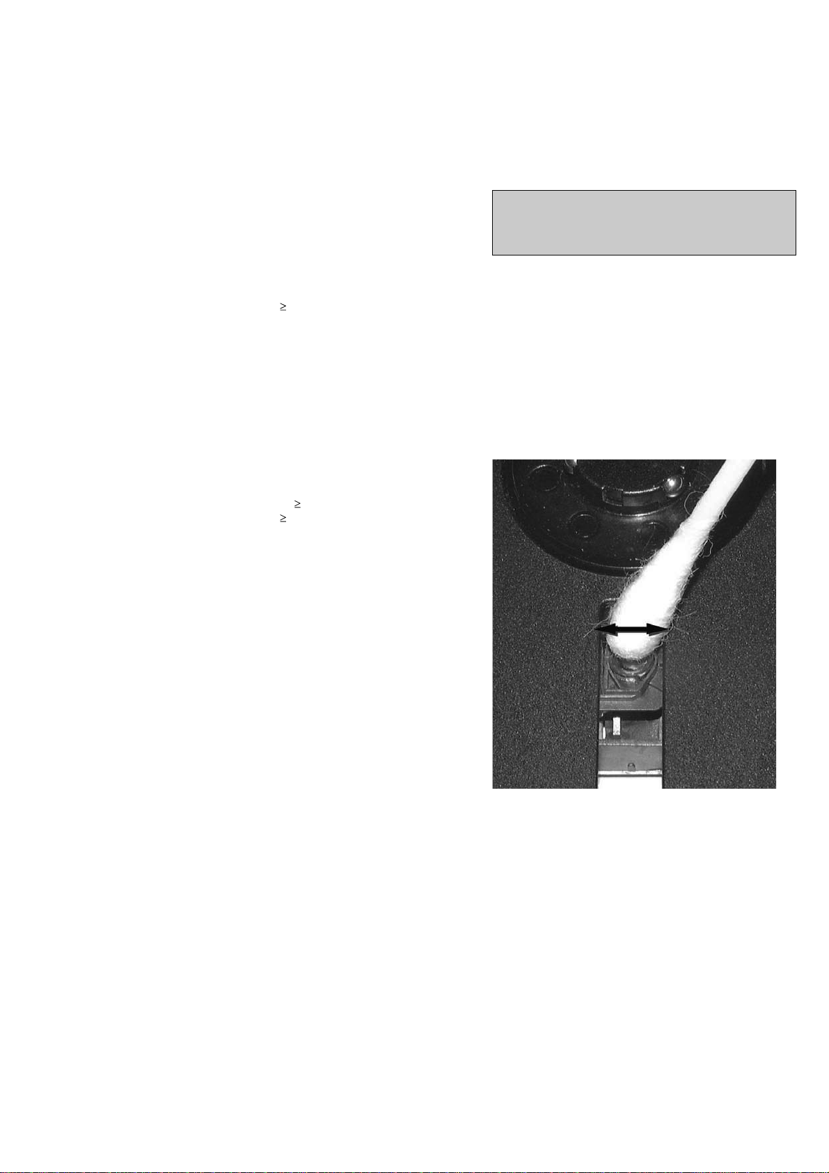
LIQUID LENS CLEANING
Before touching the lens it is advised to clean the
surface of the lens by blowing clean air over it.
This to avoid that little particles make scratches on
the lens.
Because the material of the lens is synthetic and coated
with a special anti-reflectivity layer, cleaning must be done
with a non-aggressive cleaning fluid. It is advised to use
“Cleaning Solvent
The actuator is a very precise mechanical component and
may not be damaged in order to guarantee its full function.
Clean the lens gently (don’t press too hard) with a soft and
clean cotton bud moistened with the special lens cleaner.
The direction of cleaning must be in the way as indicated in
the picture below.
CUSTOMER INFORMATION
It is proposed to add an addendum sheet to the set which
informs the customer that the set has been checked
carefully - but no fault was found.
The problem was obviously caused by a scratched, dirty or
copy-protected CD. In case problems remain, the customer
is requested to contact the workshop directly.
The lens cleaning (method ) should be mentioned in the
addendum sheet.
The final wording in national language as well as the printing
is under responsibility of the Regional Service Organizations.

DISMANTLING INSTRUCTIONS
2-1
2-1
Dismantling of the Cover Cassette and Universal Loader
1) Remove the Cover Cassette (pos 1+pos 2) in the direction as
shown in Figure 1.
2) Loosen 4 screws to remove the Cover Top (pos 62) by
sliding it out towards the rear before lifting up.
- 2 screws on the rear
- 1 screw each on the left & right side
3) Loosen 2 screws each to remove the Panel Left (pos 61)
and Panel Right (pos 60). The Panels are removed by
sliding it towards the rear and outwards.
- 1 screw on the rear
- 1 screw on the side
- see Service position A
4) Loosen 4 screws A (see Figure 2) to remove the Bracket
Module Mounting (pos 54) and Universal Loader (pos
58).
- 2 screws each on the left & right side
5) Shake up the Bracket Module Mounting and CD Loader
as shown in Figure 3 till the Cover CD (pos7) fall off.
Figure 1
Detaching the Universal Loader from the Bracket Module Mounting
1) Slide out the Loader Tray fully and remove4 screws B (see
Figure 4) to detach the Universal Loader (pos 58) from
the Bracket Module Mounting (pos 54).
- see Service position B
Figure 4
Detaching the Front Panel assembly from the Bottom/Rear assembly
1) Remove 2 screws C (see Figure 5) from the bottom of the
Cabinet Front .
2) Release the fixation of the Main Board to Bracket Combi
by removing the 1 screw and pulling the Main Board
outwards (see Figure 6).
Figure 2
3) Uncatch 2 catches on the left & right sides of the Cabinet
Front and slides the Front Panel assembly out towards
the front.
- see Service position C
Figure 5
Figure 3
7erugiF

DISMANTLING INSTRUCTIONS
2-2
2-2
Dismantling of the Front Panel assembly
1) The Knob Volume (pos 10) can be remove by pulling it
out in the direction as shown in Figure 7
2) The Knob Bass/Knob Treble (pos 11) can be remove by
pulling it out in the direction as shown in Figure 8.
3) Loosen 4 screws D (see Figure 10) to remove the Shield
Tape Deck and Module Tape Deck (pos 29).
4) Loosen 2 screws E (see Figure 9) to remove the Bracket
Top Support .
Figure 7
5) Loosen 4 screws G (see Figure 9) to remove the Bracket
Main.
6) Loosen 6 screws C4 (see Figure 11) to remove the
Display Board.
7) Loosen 4 screws H (see Figure 11) to remove the Top
Key Board.
Dismantling of the Front Panel assembly
Figure 11
Dismantling of the Rear Panel assembly
1) Loosen 3 screws K and 2 catches C5 (see Figure 12) to
remove the Tuner Board assembly.
2) Loosen 3 screws L (see Figure 12) to free the Main
Board.
3) Loosen 1 screw M (see Figure 12) to free the Mains
Socket Board.
4) Loosen 1 screw N and 2 catches C6 (see Figure 12) to
free the PanelRear (pos 53)by sliding it out towards the
rear.
Note : Tuner Board assembly and Mains Socket Board
can also be remove together with the PanelRear.
Figure 8
Figure 9
Figure 10 Figure 12

DISMANTLING INSTRUCTIONS
2-3
2-3
Repair Hints & Service Positions
1) During repair it is possible to disconnect theTuner Board
and/or CD Module completely unless the fault is sus-
pected to be in that area. This will not affect the
performance of the rest of the set.
Service position A
Service position B
Note: The flex cables are very fragile, care should be taken
not to damage them during repair. After repair, be
very sure that the flex cables are inserted properly
into the flex sockets before encasing, otherwise faults
may occurs.
Service position C
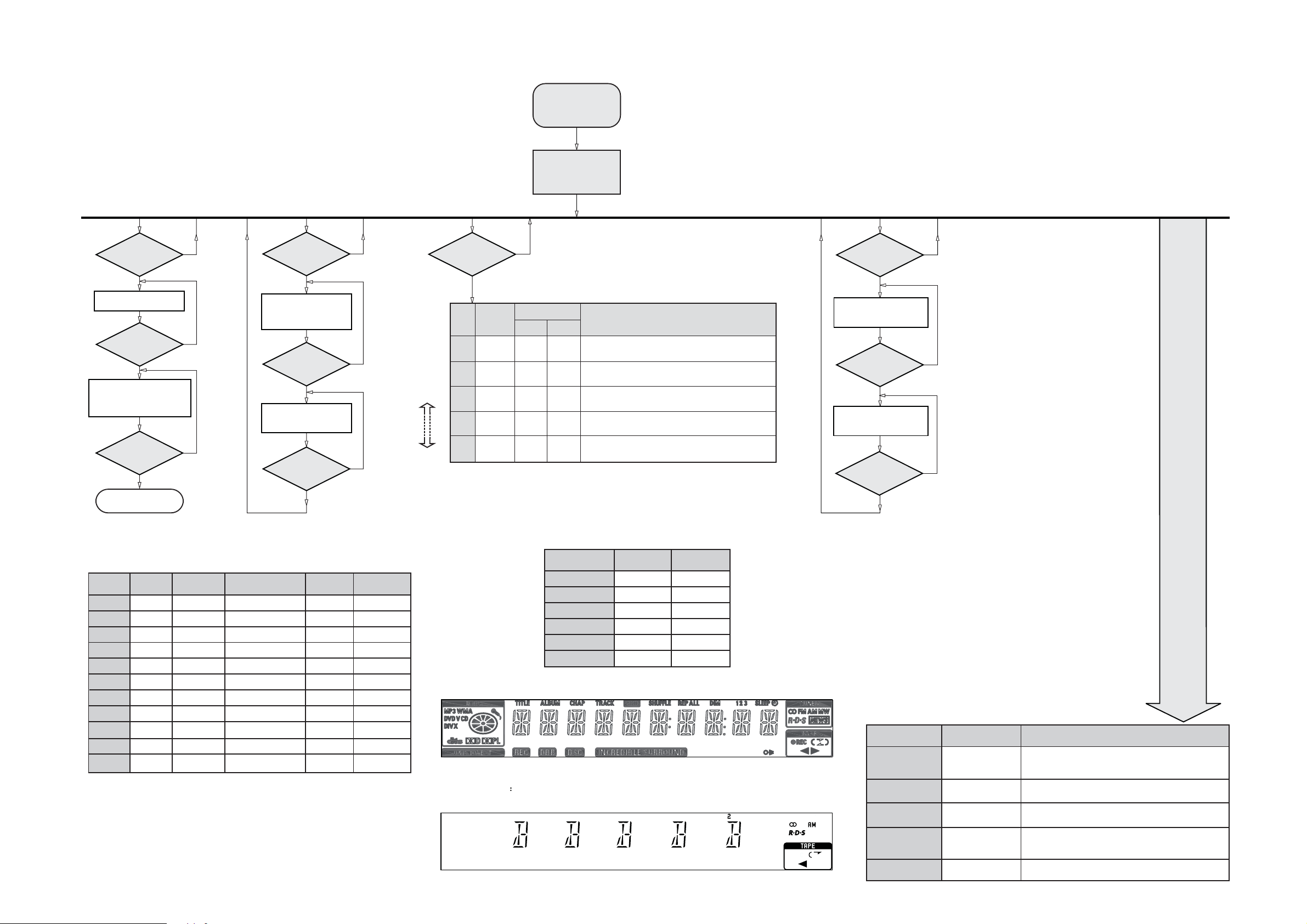
SERVICE TEST PROGRAM
3-1
To start service test program
hold PREVIEW & PLAY
buttons depressed while
plugging in the mains cord
and in standby status.
3-1
TUNER
TEST
TUNER
Button pressed?
Y
Display Tuner Version
"ccc"
TUNER
Button pressed?
Y
Service frequencies are
copied to the RAM (see Table 1)
Tuner works normally except:
PROGRAM button
Disconnect
Mains cord ?
Y
Service Mode left
Display shows the
ROM version
"S-Vyy"
(Main menu)
QUARTZ
TEST
N
N
N
TAPE
Button pressed?
Y
Display shows
32K
Output at (Display Board)
pin 19 of uP = 2048Hz
TAPE
Button pressed?
Y
Display shows
12M
Output at (Display Board)
pin 19 of uP = 2,929.6875Hz
9
Button pressed?
Y
N
CD (on RC)
Button pressed?
Y
Note : Disc should be available on the tray before entering the Service Test Mode.
STEP
DISPLAY
CD USB
N
N
Choose
level
by pressing
on the RC
Q
R
1
2
3
MO-Vnn
BITRATE
TESTING
MP3-CD MODULE
TEST
N
MESSAGE
OKAY
-
-
-
ERROR
-
-
-
ACTION
Indicates the module used.
Version of the MPEG software (nn = Version Number).
Bit rate check
Press
S refers to Service Mode
V refers to Version
yy refers to Software version number of the uProcessor
(counting up from 01 to 99)
9
to exit.
DISPLAY
TEST
DIM or RDS
Button pressed?
Y
Display shows Figure 1
and switch all LEDs on
except ECO LED
(see Table 2 Pattern 1)
DIM or RDS
Button pressed?
Y
Display shows Figure 2
and switch alternate LEDs on
(see Table 2 Pattern 2)
9
Button pressed?
Y
N
N
N
PRESET
1
2
3
4
5
6
7
8
9
10
11
Europe
"EUR"
87.5MHz
108MHz
531kHz
1602kHz
558kHz
1494kHz
87.5MHz
87.5MHz
87.5MHz
87.5MHz
98MHz
East Europe
"EAS"
87.5MHz
108MHz
531kHz
1602kHz
558kHz
1494kHz
87.5MHz
87.5MHz
87.5MHz
87.5MHz
98MHz
East Eur. Extended-band
"EAS"
65.81MHz
108MHz
74MHz
87.5MHz
531kHz
1602kHz
558kHz
1494kHz
98MHz
70.01MHz
65.81MHz
Table 1
USA
"USA"
87.5MHz
108MHz
530kHz
1700kHz
560kHz
1500kHz
98MHz
87.5MHz
87.5MHz
87.5MHz
87.5MHz
Note: * Depending on the selected grid frequency (9 or 10kHz).
By holding the ECO and TUNER buttons depressed while switching on the Mains supply,
one of the undermentioned features will be activated:
- the tuning grid frequency is toggled between 9kHz and 10kHz for the Oversea (/98) version.
- the extended FM1 (65.81MHz - 74MHz) is toggled on and off for East Eur. version.
Oversea
"OSE"
87.5MHz
108MHz
531/530kHz*
1602/1700kHz*
558/560kHz*
1494/1500kHz*
87.5/98MHz*
87.5MHz
87.5MHz
87.5MHz
98/87.5MHz*
LEDs
ECO
CD
TUNER
TAPE
AUX
Volume Rotary
Pattern 1 Pattern 2
Off
On
On
On
On
On
Table 2
Figure 1
Off
On
Off
On
Off
On
Remark Full Display Pattern function is not available for no RDS version.
Figure 2
TEST
EEPROM FORMAT
TEST
DEMO TOGGLE
ROTARY
ENCODER TEST
LEAVE SERVICE
TEST PROGRAM
Activated with
S
to Exit
9
S
B
II
Volume, Treble or Bass
Knob
Disconnect
mains cord
Various
other Tests
ACTION
"PASS" is displayed if the uProcessor read back the test patterns
correctly, otherwise "FAIL" will be displayed.
Load default data. Display shows "NEW" for 1 second.
Caution! All presets from the customer will be lost!!
Pressing this button will toggle between DEMO ON and DEMO
OFF. The DEMO status will scroll once across the Display.
Display shows value for 2 seconds.
Values increases or decreases until Volume Maximum (0dB) or
Volume Minimum (VOL MUTE) is reached.
.MORPEEehtottneseblliwsnrettaptseTTSETMORPEE
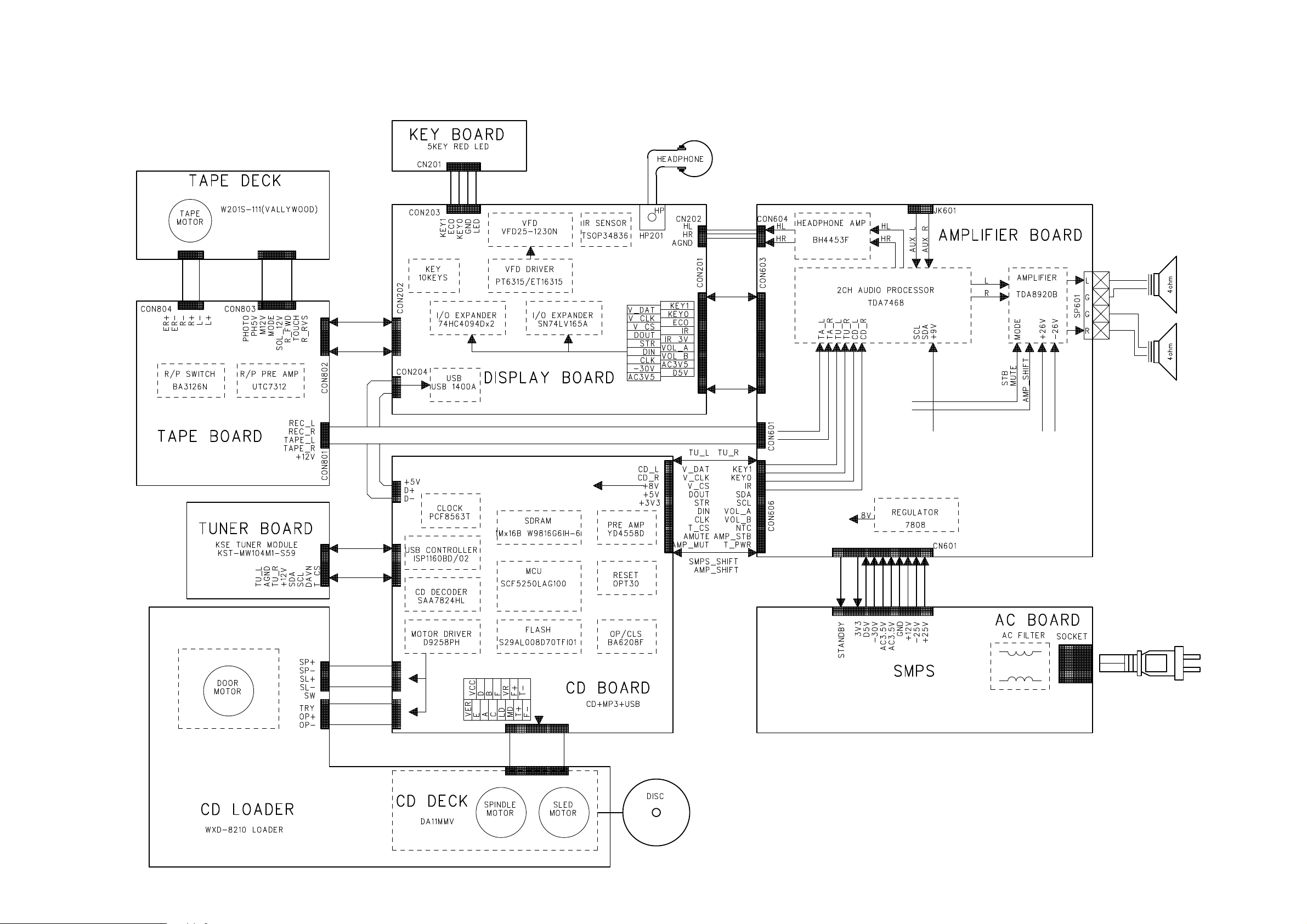
SET BLOCK DIAGRAM
4-1
4-1
 Loading...