

Page 1

MP3 Micro Hi-Fi System
MCM726
all versions
TABLE OF CONTENTS
Handling chip components ........................................................... 1-1
Leadfree and safety information ................................................... 1-2
Technical specification .................................................................. 2-1
Service tools ................................................................................. 2-1
Service measurement setup ......................................................... 2-2
Connections and controls...................................................... 3-1...3-2
Dismantling instructions ....................................................... 4-1...4-3
Block diagram................................................................................ 5-1
Wiring diagram ............................................................................. 6-1
Main Board
circuit diagram .................................................................. 7-1...7-2
layout diagram ..................................................................7-3...7-4
C Music Board
circuit diagram .................................................................. 8-1...8-2
layout diagram ..................................................................8-3...8-4
©
Copyright 2007 Philips Consumer Electronics B.V. Eindhoven, The Netherlands
All rights reserved. No part of this publication may be reproduced, stored in a retrieval
system or transmitted, in any form or by any means, electronic, mechanical, photocopying,
or otherwise without the prior permission of Philips.
VFD Board
circuit diagram. ......................................................................... 9-1
layout diagram .......................................................................... 9-2
Cassette Board
circuit diagram ........................................................................ 10-1
layout diagram ....................................................................... 10-2
Tuner Board
circuit diagram. ........................................................................11-1
layout diagram .........................................................................11-2
Rectifier Board
circuit diagram. ....................................................................... 12-1
layout diagram ........................................................................ 12-2
Exploded view diagram ............................................................... 13-1
Mechanical partslist ..................................................................... 13-2
Electrical partslist ..............................................................14-1...14-5
Supplier Bomlist
Published by LX 0717 Service Audio Subject to modification
Version 1.0
© 3141 785 31790
Page 2

1 - 1
Page 3
1 - 2
Page 4
TECHNICAL SPECIFICATIONS
2 - 1
Page 5
S
ERVICE MEASUREMENT
r
B
2 - 2
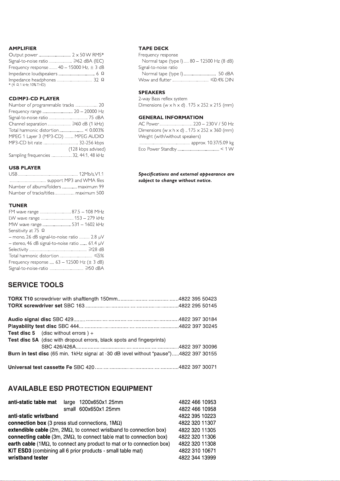
Tuner FW
RF Generator
e.g. PM5326
DUT
Bandpass
250Hz-15kHz
e.g. 7122 707 48001
LF Voltmeter
e.g. PM2534
‰
Ri=50
S/N and distortion meter
e.g. Sound Technology ST1700B
Use a bandpass filter to eliminate hum (50Hz, 100Hz) and disturbance from the pilottone (19kHz, 38kHz).
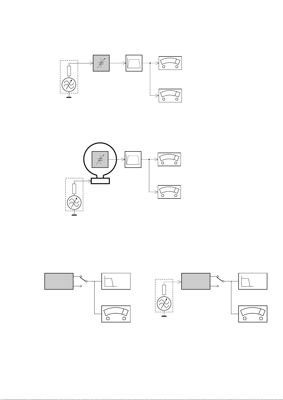
Tuner AM (MW,LW)
RF Generator
e.g. PM5326
‰
Ri=50
DUT
Frame aerial
e.g. 7122 707 89001
Bandpass
250Hz-15kHz
e.g. 7122 707 48001
LF Voltmeter
e.g. PM2534
S/N and distortion meter
e.g. Sound Technology ST1700B
To avoid atmospheric interference all AM-measurements have to be carried out in a Faraday«s cage.
Use a bandpass filter (or at least a high pass filter with 250kHz) to eliminate hum (50Hz, 100Hz).
CD RECORDER
Use Audio Signal Disc SBC429 4822 397 30184
(replaces test disc 3)
DUT
L
R
S/N and distortion meter
e.g. Sound Technology ST1700B
LEVEL METER
e.g. Sennheiser UPM550
with FF-filter
Use Universal Test Cassette Fe SBC420 4822 397 30071
LF Generator
e.g. PM5110
DUT
‰
Ri=50
L
R
S/N and distortion mete
e.g. Sound Technology ST1700
LEVEL METER
e.g. Sennheiser UPM550
with FF-filter
Page 6

CONNECTION AND CONTROLS
3 - 1
Page 7

CONNECTION AND CONTROLS
3 - 2
Page 8
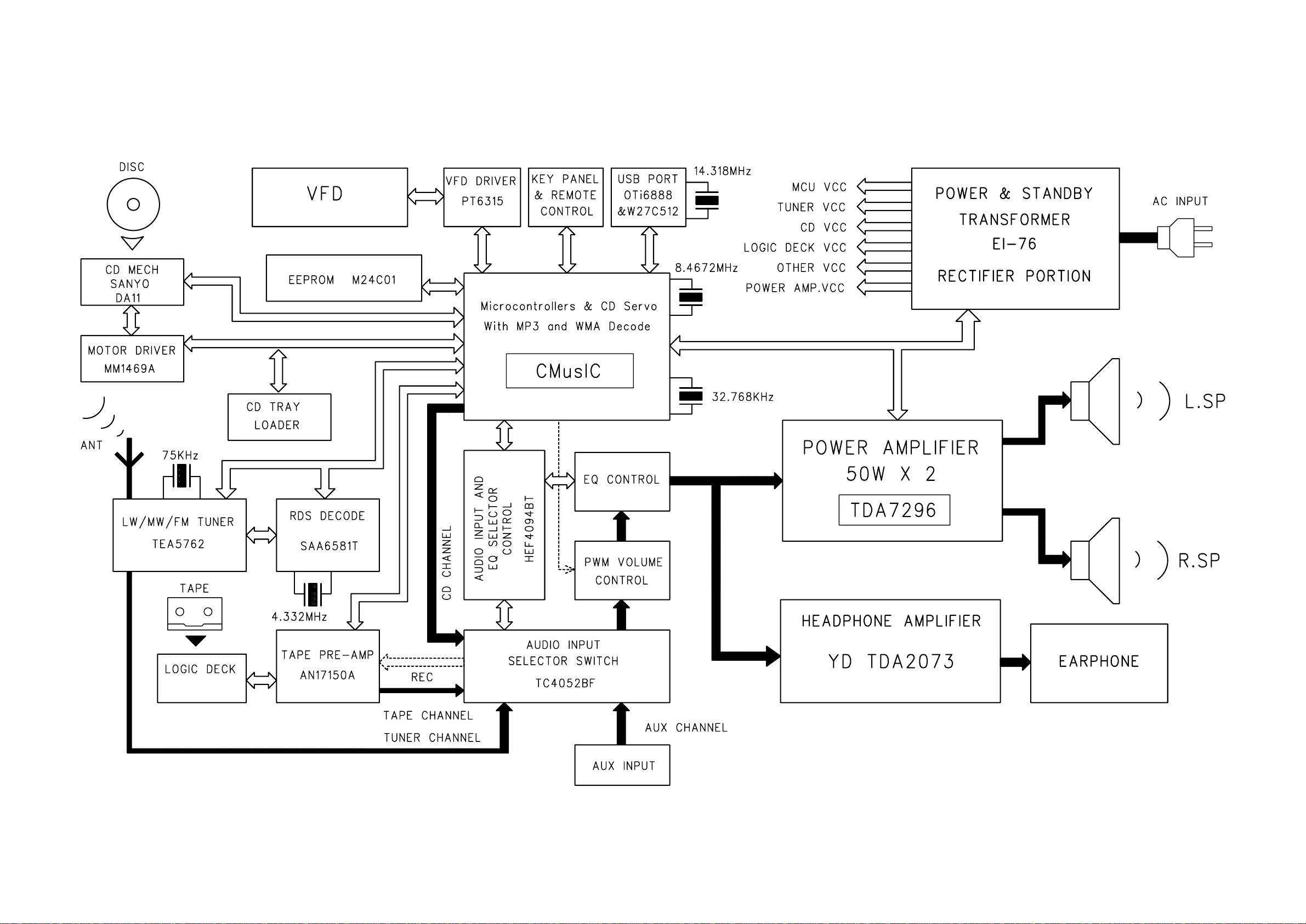
SET BLOCK DIAGRAM
5 - 1 5 - 1
Page 9

SET WIRING DIAGRAM
6 - 1
6 - 1
Page 10
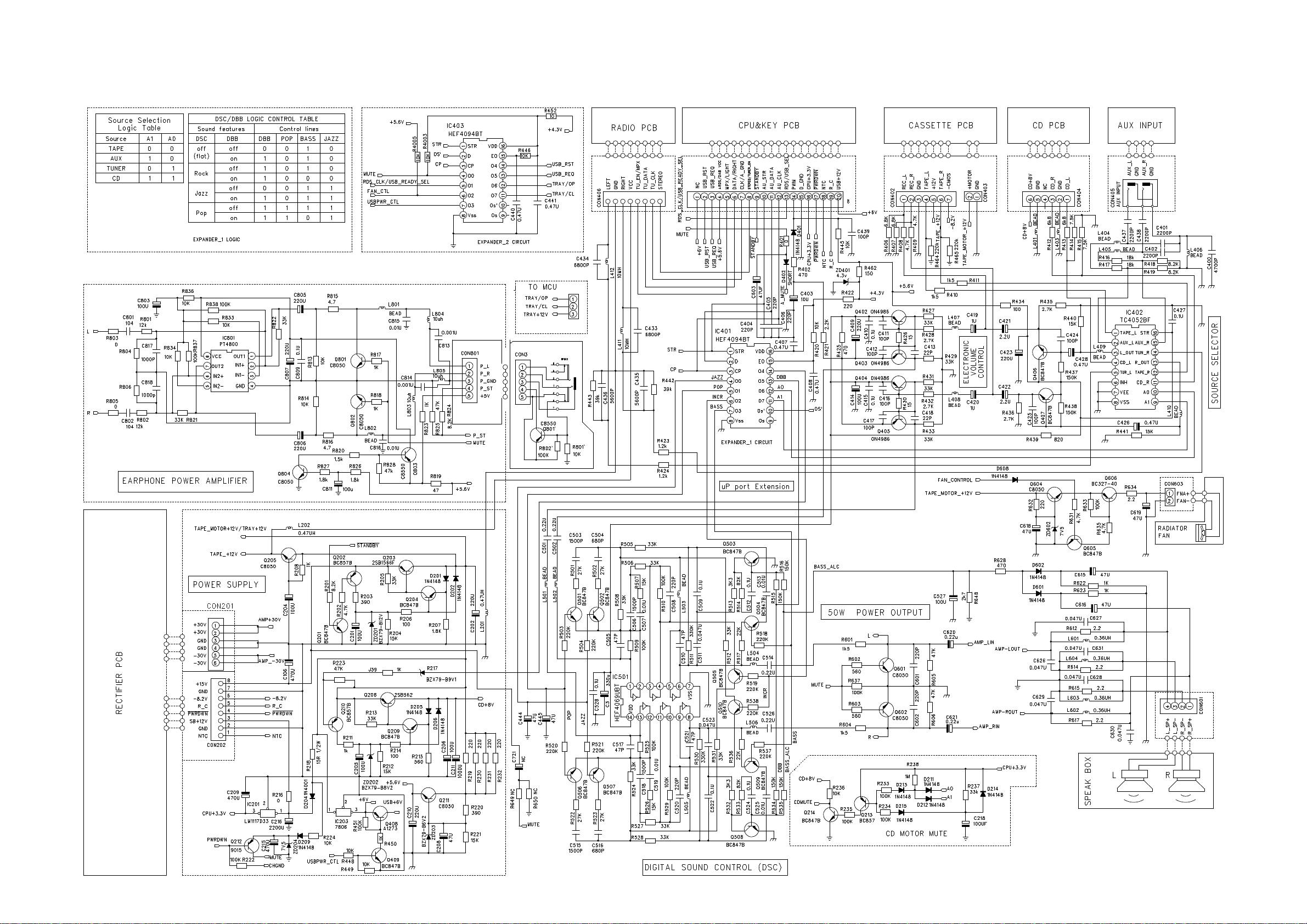
CIRCUIT DIAGRAM - MAIN BOARD
PART 1
7 - 17 - 1
Page 11

CIRCUIT DIAGRAM - MAIN BOARD
PART 2
7 - 2 7 - 2
Page 12
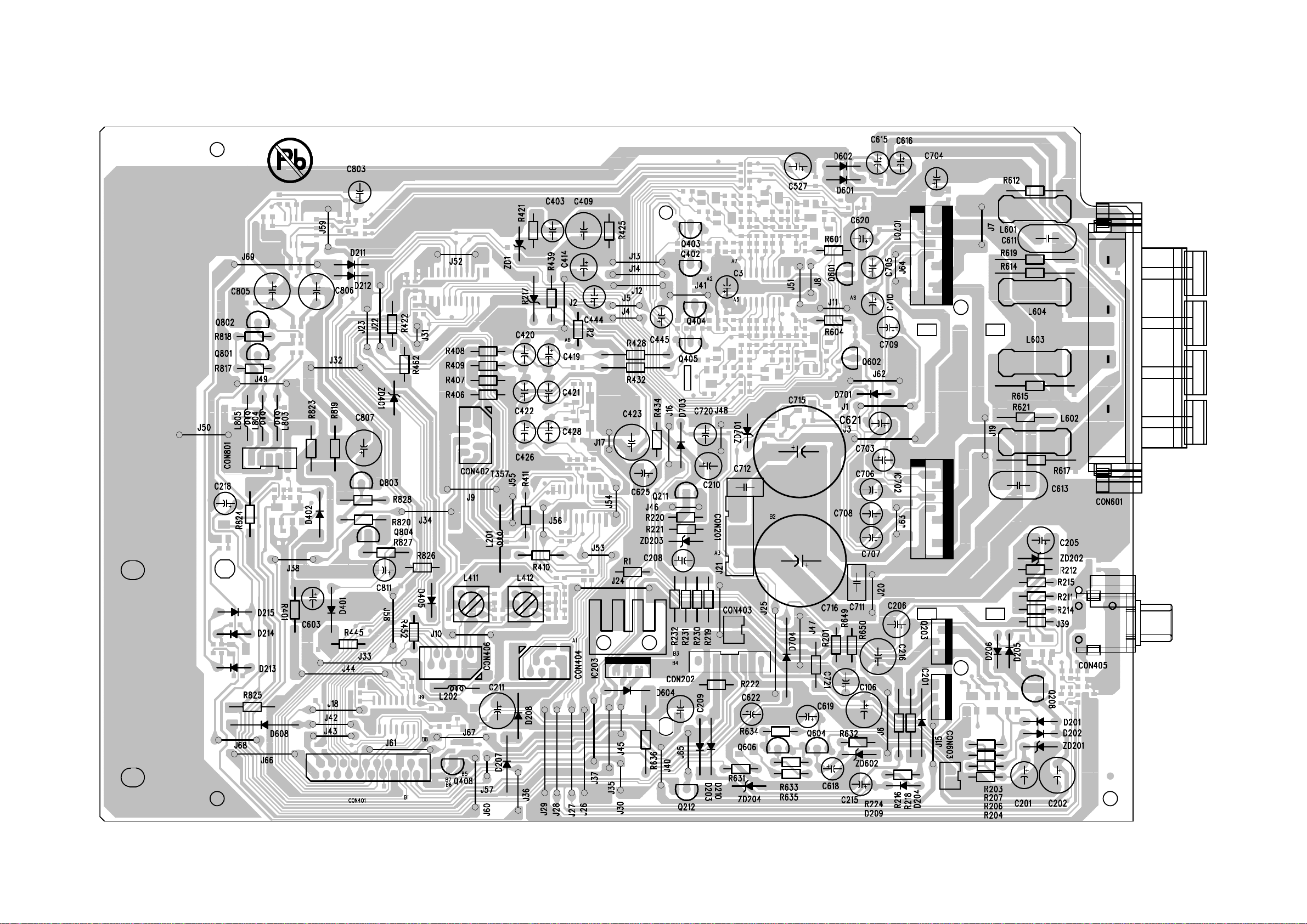
LAYOUT DIAGRAM - MAIN BOARD
COMPONENT SIDE
7 - 37 - 3
Page 13

LAYOUT DIAGRAM - MAIN BOARD
COPPER SIDE
7 - 4
7 - 4
Page 14
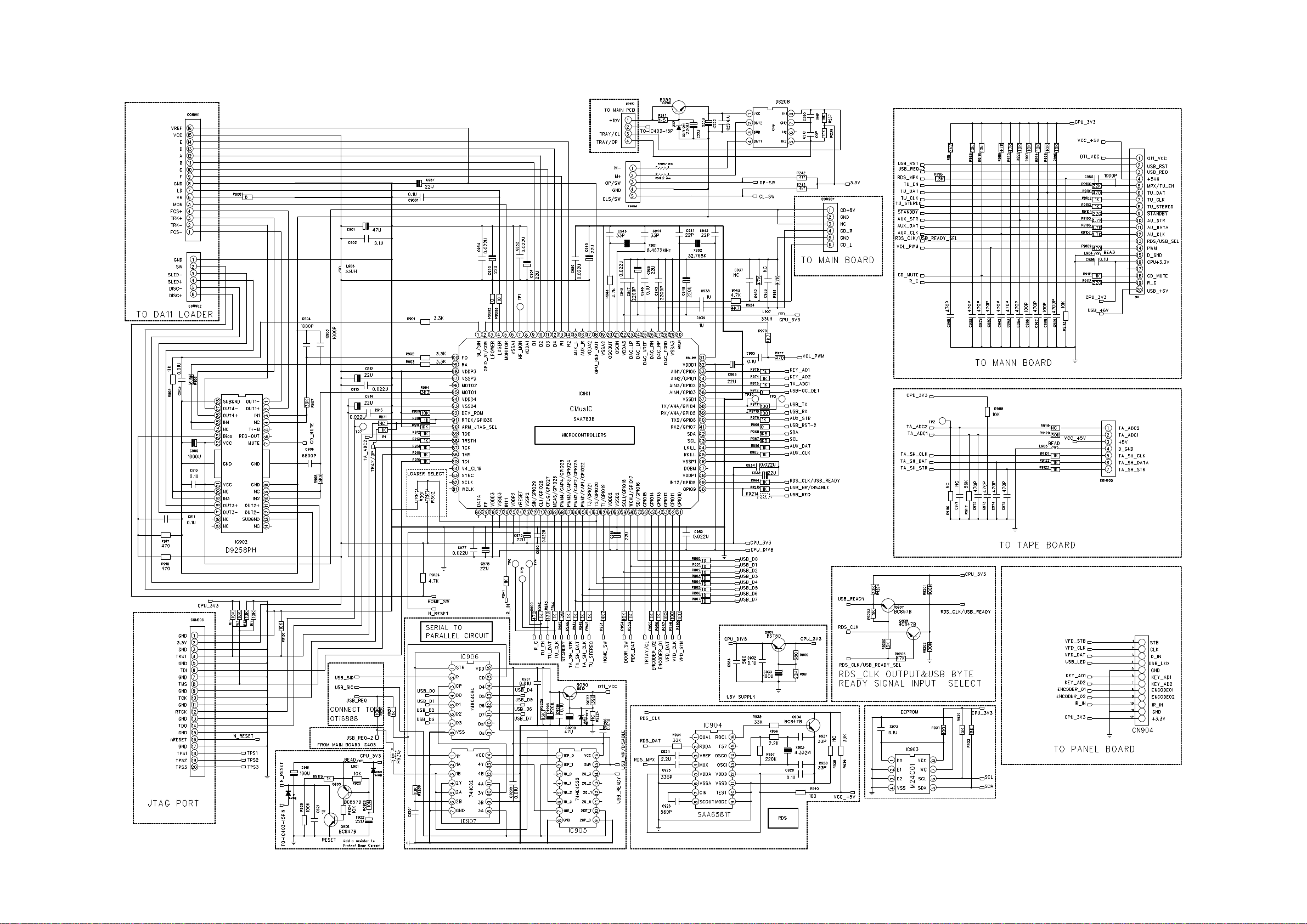
CIRCUIT DIAGRAM - C MUSIC BOARD
PART 1
8 - 1
8 - 1
Page 15

CIRCUIT DIAGRAM - C MUSIC BOARD
PART 2
8 - 2
8 - 2
Page 16

LAYOUT DIAGRAM - C MUSIC BOARD
COMPONENT SIDE
8 - 3
8 - 3
Page 17

LAYOUT DIAGRAM - C MUSIC BOARD
COPPER SIDE
8 - 4
8 - 4
Page 18

CIRCUIT DIAGARM - VFD BOARD
9 - 1
9 - 1
Page 19

LAYOUT DIAGARM - VFD BOARD
9 - 2
9 - 2
Page 20

CIRCUIT DIAGRAM - CASSETTE BOARD
10 - 1
10 - 1
Page 21

LAYOUT DIAGRAM - CASSETTE BOARD
2
1
3
4
COMPONENT SIDE
COPPER SIDE
10 - 2
10 - 2
Page 22

CIRCUIT DIAGRAM - TUNER BOARD
MIXER
varicap
FM FRONTEND
GND
PRE-
SCALER
MULTI-
PLEXER
VSTABA
AM-IF
MONO/
XTAL
AGC
CONTROL
OSC
AM DET
AM
OSC
AGC
VCC2
AGC
PUMP
AM
MIXER
DECODER
CHARGE
FM
IF1
FRONTEND
AM
VSTABB
DET
FM
CONTROL
FILTER
AM
IF
AM
DET
STEREO
STEREO
FM
IF2
RIPPLE
AGC
STABILIZER
AFC
VDD
CTRL
AGC
A
B
C
D
E
F
G
H
I
2 3 4 5 6 7 8 9 10 11 12 13 14
1 2 3 4 5 6
31576120
MW=HIGH
FM 75 OHM
PROGRAMMABLE
OUTPUT PORTS
FM-IF2
LW
VERSION DETECTION
FM-IF1
7
I
7 8 9 10 11 12 13 14
A
B
C
D
E
F
G
H
from
kHz
3170
BUFFER AMPLIFIER
VCC
1
1
2
LEGEND
* ... only assembled in FM/AM-version SMD jumper
MW=HIGH
BIRDY FILTER
/00 /02 FM/MW
/00 /02 FM/MW/LW
2169
/ SYSTEMS-CENELEC
STEREO
3
450kHz
AM-IF2
3156
RIGHT
MW
LW only
450kHz
DISCRIMINATOR
AM-AFC
AM-IF1
8
/01 FM/MW
6105
6
LW only
LW =HIGH
VERSION PROGRAMMING COMPONENTS
marked components not for LW version
MW/LW-RF
VCO
RDS only
MPX
to/from
GND
from 7101/39
LEFT
/17 FM/AM
to 1120
HN1V02H
VERSION
/14 FM-OIRT/MW
450kHz
LW=HIGH
TUNER BOARD ECO6
pin 5
54
LW ... for LW version only
MW
ENABLE/MPX
LW
component mounted
7111
AM-OSCILLATOR
CLOCK
DATA
AM FRAME AERIAL
p ...for provision only
USA ... for USA version only
2166
1n
T117
4
IF-OUT
7
9 10
8
OSC.
OUT
V
5
VCC
6
150K
3169
1110
FE450
ANT
1
2 3
T110
3168
T115
T109
3161
22K
120R
2130
22n
3142
100K
22u
2162
2137
220n
2123
390p
6
78
T106
T121
5103
1
2
3
4
T140
T118
T114
BC337-40
7105
T113
7124
100u
2129
68K
3151
BC847C
220p
2146
HN1V02H
6105-1
1
2
7
2K2
3128
2190
100n
0R
4102
*
3159
470R
YKD31-
0432
1
2
470R
3160
2149
33p
1102
1103
XH-S
1
2
22
VCC2
9 VCO
23
VDD
38
VSTABA
VSTABB
34
29
WRITE-EN
25
470n
2131
IF-GND
14
LEFT
12
LPF
24
11
MPX-IN
13
MUTE
43
NC
30
P0
31
P1
16
PILOT
4
RF-GND1
42
RF-GND2
15
RIGHT
1
RIPPLE
7 VCC1
40
AM-MIXOUT
6
AM-OSC
2
AM-RF
39
AM|FM
27
CLOCK
28
DATA
26
DIG-GND
21
FIELDSTR-IND
18
FM-DEMOD
3
FM-GND
37
FM-IF1-IN
35
FM-IF2
33
FM-IF2-IN
5 FM-OSC
8
I-TUNE
17
TEA5762
7101
10
AF-OUT
20
AFC+
19
AFC-
44
AGC
32
AM-AFC
41
AM-IF1-IN
36
AM-IF2
2107
1u
56K
3141
BAS216
6106
22K
3134
7110
BC857B
6
7
8
2u2
2138
1120
FE-BT-VK-N
1
2
3
4
5
1
2
34
6
78
5111
22K
3143
470R
3158
2143
220n
T124
330R
3154
T123
T125
T111
3190
R021R021
3191
BAS216
6120
1K
3144
100K
3156
2144
1u
47K
3171
3194
2K2
2132
470n
1132
C-PAD
2118
2p2
220R
3105
2161
100n
p
2141
100n
T105
3157
100K
2119
10p
2K2
3145
2120
18p
22p
LW
1
2
3
2124
10n
*
YKD21
1101
USA
T126
7122
BC847C
2109
10p
T116
2
3 4
6
7 8
1u
2133
5114
7P
1
3
6
22K
3137
22R
3146
HN1V02H
6105-2
5
2122
3n3
2159
33p
10u
2128
10K
3150
47R
3132
BC857C
7103
3172
5K6
2167
12p
DT-381
5121
75
T142
2147
220p
T104
BC857B
7109
2K2
3108
4K7
3123
T122
T120
T127
7112
BC547C
2134
22n
USA
22n
USA
C-PAD
1131
T141
2106
11p
20p_LW
0R
4104
*
0R
41xx
2165
100n
1130
C-PAD
10K
3180
2150
100n
BZX284-C11
6107
T102
2127
220n
2169
2n2
100K
3170
1I3
O
2125
560p
5109
2
G
470R
3152
2108
100p
3125
10K
3153
470R
330R
3193
T103
120R
3167
100R
3195
78
33K
3176
8
5122
1
2
34
6
5123
1
2
34
6
7
5110
G
2
I1O
3
5115
123
4 6
7
8
2
34
6
78
5119
1
2135
100n
2163
LW
7104
BC337-40
2145
220p
150R
3155
220n
2136
6
78
T112
T107
*
5102
7KL
1
2
34
5
3109
4K7
4101
0R
7111
BC847C
1
2
3 4
6
7
8
330R
3192
2n2
2148
5112
7P
470n
2164
ECO6 Sys-Cenelec, 010517
2140
82p
VCC1
VCC1
2139
15p
MPX
+FM
P0
P1
VDD
VDD
VCC2
VCC2
VCC1
MPX
P01
P1
P0
P01
P0
VDD VDD
AM/FM
+FM
AM/FM
P0
1101 A2
1102 B1
1103 E2
1110 B2
1120 E14
1130 A2
1131 C2
1132 F13
2102 B1
2105 A2
2106 E3
2107 E4
2108 G3
2109 G3
2118 H6
2119 H6
2120 H6
2122 I6
2123 H6
2124 H6
2125 H6
2127 E7
2128 B8
2129 C7
2130 F11
2131 F8
2132 F8
2133 F8
2134 I8
2135 I9
2136 H14
2137 H13
2138 F9
2139 G9
2140 G9
2141 F10
2143 G12
2144 G11
2145 E11
2146 E12
2147 E12
2148 E12
2149 H7
2150 A10
2159 D5
2161 C11
2162 H12
2163 D11
2164 G10
2165 C7
2166 E11
2167 E11
2169 G8
2180 C4
2190 C3
2191 C3
3105 D5
3108 D2
3109 G4
3123 H3
3125 H2
3128 H3
3130 I9
3131 I9
3132 G4
3134 H6
3135 E7
3137 H7
3141 E7
3142 E6
3143 G7
3144 G8
3145 F8
3146 G13
3150 H12
3151 H12
3152 G14
3153 G13
3154 F13
3155 G12
3156 C12
3157 D12
3158 E13
3159 D13
3160 D13
3161 D13
3167 F12
3168 F11
3169 E11
3170 D12
3171 G12
3172 G12
3176 H7
3180 I3
3190 B6
3191 B7
3192 B6
3193 B4
3194 C4
3195 C3
4101 E2
4102 F3
4104 H5
5102 E3
5103 F2
5109 B9
5110 B10
5111 A9
5112 A11
5114 B11
5115 E7
5118 G9
5119 G9
5121 E11
5122 H5
5123 G5
6105-1 E4
6105-2 G6
6106 D4
6107 G13
6120 C13
7101 C8
7103 H8
7104 D2
7105 F4
7109 H3
7110 H12
7111 C13
7112 G12
7122 H4
7124 H7
T102 B2
T103 B2
T104 B6
T105 E2
T106 E2
T107 C3
T109 D5
T110 D5
T111 E5
T112 F7
T113 A9
T114 B11
T116 F10
T117 F13
T118 G11
T120 F13
T121 F13
T122 E13
T123 E13
T124 G14
T125 F14
T126 F13
T127 F13
T140 F11
T141 F10
T142 F10
p
p
p
2191
100u
2102
100n
2105
USA
100n
5118
1nH
15n
15n
3131
820R
3130
820R
1K
3135
2180
10n
8.3V
7.5V
7.2V
9V
11V
8.2V
0.1V
1.2V
1.6-8V
5
1
A
3
2
D
C
4
...V MW mode
...V LW mode
voltages measured while
set is tuned to a strong transmitter
0.7V
0.7V
1.3V
0.7V
0V
7.4V
0V
7.5V
0.7V
0V
mono 4.8V
0V
0V
stereo 0.4V
7.5V
7.5V
1.4V
1.6-8V
0.1V
0V
0V
2V
0.2V
1.4V
1.4V
0.4V
0.7V
1.4V
1.4V
1.1V
0.7V
1.4V
0.6V
0.6V
0.8V
0.15V
...V FM mode stereo
EVM
V
B
8V
6.7V
8.3V
0.7V
0V
0V
0V
0.1V
0V
11V
2V
1.1V
1.1V
1V
1V
8.2V
7.8V
1.2V
0V
8.9V
12Vtyp
8.2V
mono 4.8V
stereo 0.2V
1.4V
0V
0V
0V
0V
0.1V
0V
0.7V
0.1V
0V
0.2V
(10-14V)
9.6V
12V
8.9V
8.2V
7.5V
8.3V
8.2V
0.8V
1.2V
0.7V
1.3V
1V
8.2V
7.8V
1-8V
0V
5V
0V
152kHz, 50mV
pp
stereo stereomono
Signal path
FM
AF - left/right
AM
MPX (Audio Frequency)
11 - 1
11 - 1
Page 23

LAYOUT DIAGRAM - TUNER BOARD
98MHz
Waverange Input frequency Input Tuned to Adjust Output Scope/Voltmeter
VARICAP ALIGNMENT
FM - VCO
FM RF (channel separation)
AM IF
AM RF
3)
108MHz
87.5MHz
check
check
8V 1.2V
1.6V 0.5V
8V 0.2V
6.9V 0.2V
1.1V 0.4V
152kHz 1kHz
1)
98MHz 3142
198kHz 3015zHk891
5111
FM
87.5 - 108MHz
(50kHz grid)
1602kHz
531kHz
5123
check
MW
531 - 1602kHz
(9kHz grid)
8V 0.2V
1.1V 0.4V
279kHz
153kHz
5122
check
LW
153 - 279kHz
(3kHz grid)
FM
FM
LW
558kHz558kHz
1494kHz
5102
6012zHk4941
MW
MW
98MHz, 1mV
continuous wave
98MHz, 1mV
90% Left + 9% pilot
mod=1kHz
IF coil
inside
FM
frontend
1110
1
3
5
5
A
FM - IF
0mV 3mV5119
FM
10.7MHz, 45mV
continuous wave
2D
right channel min.
4A
0mV 2mV5114
2
C
Repeat
C
5112
1)
If sensitivity of frequency counter is too low adjust to max. channel separation
(input signal: stereo left 90% + 9%, adjust output on right channel to minimum)
2)
RC network serves for damping the IF-filter while adjusting the other one.
3)
For AM RF adjustments the original frame antenna has to be used!
TUNER ADJUSTMENT TABLE
( ECO6 Cenelec FM/MW - and FM/MW/LW - versions with AM-frame aerial )
max.
symmetric
f
o
max.
symmetric
f
o
ECO6 Sys Cenelec, 190599
B
f = 30kHz
V
RF
as low as
possible
MW has to be aligned before LW.
3-band
2-band
Note: The FM-frontend unit has already been adjusted by the factory
and needs therefore no further adjustments for service purposes.
2141
shortcircuit
to block AFC
21
IC 7101
see
remark
2)
220R
100nF
36
IC 7101
220R
100nF
40
IC 7101
450kHz
connect pin 6 of
IC 7101 (AM Osc.)
with 3.3k to Vcc
AM AFC
MW
continuous wave
VRF = 2mV
f = 10kHz
VRF = 0.5mV
(as low as
possible)
Use Service Testprogram. By selecting the TUNER TEST test frequencies will be stored as preset frequencies automatically.
AM FRAME AERIAL
FM 75
FM FRONTEND
Birdy Filter
ECO6 Sys-Cenelec, layout stage .8, 200803
1101 B5
1102 B5
1103 C5
1110 B4
1120 A4
1130 A5
1131 C5
1132 A4
2106 B4
2107 B3
2128 A3
2129 B3
2133 C1
2138 B1
2144 B1
2162 A4
2191 B4
3142 C2
5102 C4
5103 C4
5109 B3
5110 A2
5111 A3
5112 A2
5114 A2
5115 C2
5119 B2
5121 B2
5122 C3
5123 C3
7104 C4
7105 C5
7112 B1
9101 A2
9102 B2
9103 A1
9104 B1
9105 B1
9106 B1
9107 B4
9108 B3
9109 C2
9110 A4
9111 A3
TUNER BOARD ECO6
Systems - Cenelec
/ componentside view
B
A
11 - 211 - 2
Page 24

CIRCUIT DIAGRAM - RECTIFIER BOARD
12 - 112 - 1
Page 25

LAYOUT DIAGRAM - RECTIFIER BOARD
12 - 2
12 - 2
Page 26

EXPLODED VIEW DIAGRAM
13 - 1 13 - 1
Page 27

13 - 2
MECHANICAL PARTSLIST
1 996510002333 TOP CABINET
3 996510000871 CD TRAY LOADER
4 996510002348 BRACKET CD DOOR
5
6 996510002349 CD TRAY
14 996510002347 BRACKET -TOP BUTTON
15 996510002338 POWER KEY
16 996510002341 TOP KEY CLUSTER BUTTONS
17 996510002339 MODE KEY CLUSTER BUTTONS
18 996510002332 FRONT CABINET
19 996510002342 POWER LENS
20 996510002343 DISPLAY LENS
21 996510002337 VOLUME KNOB
22 996510002344 CONTROL PANEL
25 996510002346 CASSETTE DOOR
26 994000004801 BRACKET - CASSETTE DOOR
27 996510002331 CASSETTE DOOR SPRING
30 996510002340 CD CONTROL KEY CLUSTER BUTTONS
34 994000001434 CASS DECK MECHANISM W991S
35 994000001409 CD DOOR GEAR HOLDER
996510002345 CD DOOR
36 996510002350 CASSETTE DOOR DAMPING GEAR
57 994000003257 DC BRUSHLESS FAN JD6025MS11150W0
63 994000003234 RUBBER FOOT 11x11x6mm
65 996510002336 REAR CABINET
75 996510002334 LEFT CABINET
78 994000005773 TRANSFORMER EI-76 230V 50HZ
84 996510002335 RIGHT CABINET
88 996510001074 CD SPRING DIM:0.5MM
89 996510001075 CD SPRING DIM:0.6MM
89 996510000868 CD DAMPER PINK 658F HARDNESS 40JIS
90 994000005786 CD MECHANISM DA11VF (SANYO)
!
994000005777 SWITCH SPRING FOR PUSH LOCK SUS304
ACCESSORIES
SPEA 996510002351 WOODEN SPEAKER (LEFT+RIGHT) ONE SET
RC 996510002352 REMOTE CONTROL FOR #MCM726
ANT 994000003268 PIG TAIL ANTENNA WIRE BLACK
AML 994000001419 AM LOOP FRAME ASSY INJ. BLACK
ACL 994000001451 6 FEET VDE APPRROVED POWER CORD
Note: Only these parts mentioned in the list are
normal service parts.
Page 28

14 - 1
ELECTRICAL PARTSLIST - MAIN BOARD
- IC & TRANSISTORS -
IC501 994000003198 IC HEF4069UBT SOT108-1 SMT
IC401 994000003199 I.C. HEF4094BT
IC403 994000003199 I.C. HEF4094BT
IC801 996500039259 I.C. PT4800(L) DIP-8 PIN
IC402 994000003201 I.C. TC4052BF SWITCHING
IC203 996510002327 I.C.KIA7806API-U/P TO-220IS
IC201 994000005724 I.C. VOL. REGULATOR LD1117AL-3.3V-D
IC701 994000005726 IC TDA7296 MULTIWATT15V
IC702 994000005726 IC TDA7296 MULTIWATT15V
Q203 994000001436 TRANSISTOR 2SB1566-F LEAD FREE
Q208 994000005727 TRANSISTOR 2SB562C TO-92MOD
Q408 994000005729 TRANSISTOR KTA1273 TO-92L
Q402 996500004928 TRANSISTOR ON4986 (9340-447-50126)
Q403 996500004928 TRANSISTOR ON4986 (9340-447-50126)
Q404 996500004928 TRANSISTOR ON4986 (9340-447-50126)
Q405 996500004928 TRANSISTOR ON4986 (9340-447-50126)
- MISCELLANEOUS -
996510002328 16P FFC CABLE 100MM P=1.0MM WHITE
994000003259 6P FFC CABLE L=120MM
994000005767 20 PINS FFC CABLE TYPE A
994000005768 FFC CABLE 12PINS L=180M
994000003263 FFC CABLE 180MM 7P WHITE TYPE B
994000005769 8PINS FFC CABLE L=190MM
PCB7 996510002326 MCM726 MAIN PCB ASSY
Note: Only these parts mentioned in the list are
normal service parts.
Page 29

14 - 2
ELECTRICAL PARTSLIST - CASSETTE BOARD
- MISCELLANEOUS -
994000005719 I.C. SM AN17150A-E2V(MATJ)
994000003199 I.C. HEF4094BT
994000001433 TRANSISTOR (FET) J112
PCB1 994000003192 CASS PCB ASSY
Note: Only these parts mentioned in the list are
normal service parts.
Page 30

14 - 3
ELECTRICAL PARTSLIST - RECTIFIER BOARD
- MISCELLANEOUS -
PCB2
!
996510002317 RECIFIER PCB ASSY
!
996510000389 FUSE 2.5A 250V D5X20MM GLASS
!
994000003224 FUSE 6.3A 250V D5X20MM GLASS
!
994000003225 FUSE 0.315A 250V D5X20MM GLASS
994000003226 AC LINE FILTER 400UH +-30%
994000001448 9V DC RELAY 10A ME-7-009-HL LEAD
994000003228 TRANSISTOR 2N5401 TO-92 (WTC)
!
994000005772 TRANS. 230V 50HZ 12V@0.1A EI-28
Note: Only these parts mentioned in the list are
normal service parts.
Page 31

14 - 4
ELECTRICAL PARTSLIST - C MUSIC BOARD
- IC & TRANSISTORS -
IC901 996510002330 IC PROGRAMMED FOR MCM726
U202 996510000738 IC EPROM FOR (MCM720) ICE27C512-70
U201 994000005747 IC OTI6888-G LQFP-64
IC907 994000005748 I.C. 74HC02DB SSOP14
IC906 994000005749 I.C. 74HC4094DB SSOP16
IC905 994000005751 I.C. 74HC4520DB SSOP16
IC908 996510001069 I.C. D6208 SOP8
IC902 994000005753 I.C. D9258PH (LEAD FREE)
IC903 994000003272 I.C. M24C01-RDW6T
IC904 994000003215 RDS IC SAA6581T/V1 SOT162-1
Q901 996510000378 TRANSISTOR BST50 (SMD) LEAD FREE
Q204 994000005729 TRANSISTOR KTA1273 TO-92L
- MISCELLANEOUS -
PCB8 996510002329 MCM726 C MUSIC ASSY
Y1 994000005741 CRYSTAL 14.318 MHZ 20PF +/-20PPM
X902 994000003208 CRYSTAL 32.768KHZ 12.5PF +-10 PPM
X903 994000003209 CRYSTAL 4.332MHZ HC-49/S LEAD FREE
X901 994000005742 CRYSTAL 8.4672 MHZ 20PF+-30PPM
Note: Only these parts mentioned in the list are
normal service parts.
Page 32

ELECTRICAL PARTSLIST
14 - 5
PCB3 994000005732
994000005736 I.C. TEA5762H/V1 LEAD FREE
994000005737 FM TUNER MODULE #MCM390
PCB4 996510002318
LED701 994000005763 LED INGICATOR RED CL-3R4SD-16
SW701 996510002319 TACT SWITCH EVQ11L04M
SW703 996510002319 TACT SWITCH EVQ11L04M
SW704 996510002319 TACT SWITCH EVQ11L04M
SW705 996510002319 TACT SWITCH EVQ11L04M
PCB5 996510002320
RS701 994000005759 INFRARED RECEIVER IRM502H-S
VFD701 994000005761 VFD DISPLAY
LED1 994000005762 LED BLUE (1L0345B22E0CB002)
LED2 994000005762 LED BLUE (1L0345B22E0CB002)
LED3 994000005762 LED BLUE (1L0345B22E0CB002)
U1 994000003214 VFD DRIVER IC PT6315 L.F.
LCD 994000005757 LCD BRACKET
PCB5 996510002321
HP801 996510002322 3.5MM STEREO JACK TC38-103-DG-010
Q801 996510002323 TRANSISTOR S8550 SMD TYPE
TUNER P.C.B. ASSY
MCM726 TOP KEY PCB ASSY-1
MCM726 TOP KEY PCB ASSY-2
MCM726 KEY PCB ASSY-1
PCB6 996510002324
EN701 996510002325 ENCODER EC121102F2B-HA1-009
SW702 994000001444 TACT SWITCH TSA-065001-150
SW706 994000001444 TACT SWITCH TSA-065001-150
SW707 994000001444 TACT SWITCH TSA-065001-150
SW708 994000001444 TACT SWITCH TSA-065001-150
SW709 994000001444 TACT SWITCH TSA-065001-150
SW710 994000001444 TACT SWITCH TSA-065001-150
SW711 994000001444 TACT SWITCH TSA-065001-150
SW712 994000001444 TACT SWITCH TSA-065001-150
SW713 994000001444 TACT SWITCH TSA-065001-150
SW714 994000001444 TACT SWITCH TSA-065001-150
MCM726 KEY PCB ASSY-2
Note: Only these parts mentioned in the list are
normal service parts.
Page 33

層次 物品代碼 品名 BOM 位置
_1 115MCM510V22C-MUS
__2 115MCM510V22C-EET
___3 115MCM510V22C-ATS
____4 EPBMCM390L01A
___3 A600041
___3 ECACD101G0603JCTA
___3 ECACD102G0603KBTA
___3 ECACD103G0603KDTA
___3 ECACD104D0603KDTA
___3 ECACD105D0603KBTA
___3 ECACD152G0603KBTA
___3 ECACD221G0603JCTA
___3 ECACD222G0603KDTA
___3 ECACD223E0603KDTA
___3 ECACD332G0603KDTA
___3 ECACD333D0603KDTA
___3 ECACD471G0603JCTA
___3 ECACD472G0603KDTA
___3 ECAER105G5011MATA
___3 ECAER106G5011MATA
___3 ECAER226G5011MATA
___3 ECAER227D6311MATA
*替代料*
ECAER227D6311META AL.E.CAP 220UF 16V 6.3X11MM M% 105C TAPE Ref No:
___3 ECAER476E5011MATA
___3 ECAMR104L1012KATA
___3 ECAMR682L6095KATA
___3 EDDEPTX79B8V2A
___3 EDDRPT1N4001ZA
___3 EDDSPT1N4148ZA
___3 EFTE140BK14A
___3 EJA163HR02PBD
___3 EJA250FR07PBA
___3 ENCDTAN17150ATAA
___3 ENCDTHEF4094BTZA
___3 ENDX222K03R2TA
___3 ERECD0R0010JBTA
___3 ERECD100K10JBTA
___3 ERECD100R10JBTA
___3 ERECD10K010JBTA
___3 ERECD120K10JBTA
___3 ERECD120R10JBTA
___3 ERECD150R10JBTA
___3 ERECD15K010JBTA
___3 ERECD180R10JBTA
___3 ERECD18K010JBTA
___3 ERECD1K0010JBTA
___3 ERECD1K2010JBTA
___3 ERECD1K5010JBTA
___3 ERECD1M0010JBTA
___3 ERECD22K010JBTA
___3 ERECD27K010JBTA
___3 ERECD2K2010JBTA
___3 ERECD300R10JBTA
___3 ERECD330K10JBTA
___3 ERECD33R010JBTA
MANUAL INSERTION ASSEMBLY 手插零件底板組裝
PCBA ELECTRICAL PARTS PHANTOM 底板組裝電子料
AUTO INSERTION ASSEMBLY 機插零件底板組裝
CASS PCB PANEL T=1.6MM 94HB 底板
BARE COPPER WIRE DIA:0.5MM (LB) 錫水銅線
CHIP CAP. 100PF50V (0603) J% NPO 微型电容
CHIP CAP. 1000PF50V (0603) K% Y5P 微型电容
CHIP CAP. 0.01UF50V (0603) K% Y5R 微型电容
CHIP CAP. 0.1UF16V (0603) K% Y5R 微型电容
CHIP CAP. 1UF16V (0603) K% Y5P 微型电容
CHIP CAP. 1500PF50V (0603) K% Y5P 微型电容
CHIP CAP. 220PF50V (0603) J% NPO 微型电容
CHIP CAP. 2200PF50V (0603) K% Y5R 微型电容
CHIP CAP. 0.022UF25V (0603) K% Y5R 微型电容
CHIP CAP. 3300PF50V (0603) K% Y5R 微型电容
CHIP CAP. 0.033UF16V (0603) K% Y5R 微型电容
CHIP CAP. 470PF50V (0603) J% NPO 微型电容
CHIP CAP. 4700PF50V (0603) K% Y5R 微型电容
AL.E.CAP 1UF 50V 5X11MM M% 85C TAPE 电解电容
AL.E.CAP 10UF 50V 5X11MM M% 85C TAPE 电解电容
AL.E.CAP 22UF 50V 5X11MM M% 85C TAPE 电解电容
AL.E.CAP 220UF 16V 6.3X11MM M% 85C TAPE 电解电容
AL.E.CAP 47UF 25V 5X11MM M% 85C TAPE 电解电容
MYLAR 0.1UF100V 10X12MM K% 85C TAPE 聚酯薄膜电容
MYLAR 6800PF100V 6X9.5MM K% 85C TAPE 聚酯薄膜电容
DIODE BZX79-B8V2 SOD27 TAPE FORM 二極管
DIODE 1N4001 TAPE FORM 二極管
DIODE 1N4148 TAPE FORM 二極管
AM OSC BLACK 10MM 中周
2 PINS HEADER P=2.0MM STRAIGHT TYPE 插座
7P FPC CONNECTOR P=1.25MM 插座
I.C. SM AN17150A-E2V(MATJ) R (PANASONIC) 集成塊
I.C. HEF4094BT 集成塊
AXIAL INDUCTOR 2.2UF K% D3.2MM 电阻型电感
CHIP RESISTOR 0OHM 1/10 W J% (0603) 微型电阻
CHIP RESISTOR 100 KOHM 1/10 W J% (0603) 微型电阻
CHIP RESISTOR 100OHM 1/10 W J% (0603) 微型电阻
CHIP RESISTOR 10 KOHM 1/10 W J% (0603) 微型电阻
CHIP RESISTOR 120 KOHM 1/10 W J% (0603) 微型电阻
CHIP RESISTOR 120OHM 1/10 W J% (0603) 微型电阻
CHIP RESISTOR 150OHM 1/10 W J% (0603) 微型电阻
CHIP RESISTOR 15 KOHM 1/10 W J% (0603) 微型电阻
CHIP RESISTOR 180OHM 1/10 W J% (0603) 微型电阻
CHIP RESISTOR 18 KOHM 1/10 W J% (0603) 微型电阻
CHIP RESISTOR 1 KOHM 1/10 W J% (0603) 微型电阻
CHIP RESISTOR 1.2 KOHM 1/10 W J% (0603) 微型电阻
CHIP RESISTOR 1.5 KOHM 1/10 W J% (0603) 微型电阻
CHIP RESISTOR 1 MOHM 1/10 W J% (0603) 微型电阻
CHIP RESISTOR 22 KOHM 1/10 W J% (0603) 微型电阻
CHIP RESISTOR 27 KOHM 1/10 W J% (0603) 微型电阻
CHIP RESISTOR 2.2 KOHM 1/10 W J% (0603) 微型电阻
CHIP RESISTOR 300OHM 1/10 W J% (0603) 微型电阻
CHIP RESISTOR 330 KOHM 1/10 W J% (0603) 微型电阻
CHIP RESISTOR 33OHM 1/10 W J% (0603) 微型电阻
Loc: 9701-9707.6770.R4
Loc: 2701-2704.2711.2712.2786.
Loc: 2621.2731.
Loc: 2781
Loc: 2625.2799.C1.C2.
Loc: 2721.2722.2732.
Loc: 2790.2791.
Loc: 2725.2793.2794.
Loc: 2723.2769.2770.2724.2727.2728.
Loc: 2729.2730.2743.2788.
Loc: 2709.2710.
Loc: 2787.2789.2747.
Loc: 2622.2623.
Loc: 2782
Loc: 2768.2785.
Loc: 2798
Loc: 2797.2780.
Loc: 2761.2715.2716.
Loc: 2796
Loc: 2713.2714.
Loc: 2784
Loc: 6777
Loc: 6612
Loc: 6772-6774.6776.6778.
Loc: 5703
Loc: 1703
Loc: 1701.1706.
Loc: 7720
Loc: 7610
Loc: 5701
Loc: 3624.3628.
Loc: 3711.3712.
Loc: 3768
Loc: 3610
Loc: 3749.3750.
Loc: 3777
Loc: 3772
Loc: 3764
Loc: 3774
Loc: 3737.3738.3626.
Loc: 3746.3745.3771.
Loc: 3770
Loc: 3780
3735.3736.3769.3790.3800.3786.R2
Loc: 3733.3734.3608.3791.3723.3724
Loc: 3607.3609.3611.3630.
Loc: 3801
Loc: 3779
Loc: 3709.3710.
3739.3740.3678.3680.3789.3686.3614.R
___3 ERECD47K010JBTA
___3 ERECD4M7010JBTA
___3 ERECD4R7010JBTA
___3 ERECD56K010JBTA
___3 ERECD680R10JBTA
___3 ERECD6K8010JBTA
___3 ERECR1K8006JLTA
___3 ERECR22R006JLTA
___3 ETRDT8050MZZA
___3 ETRDT8550LT1A
___3 ETRDTBC81725A
___3 ETRDTBC847BLA
*替代料*
ETRDTBC847BZA TRANSISTOR BC847B Ref No:
CHIP RESISTOR 47 KOHM 1/10 W J% (0603) 微型电阻
CHIP RESISTOR 4.7 MOHM 1/10 W J% (0603) 微型电阻
CHIP RESISTOR 4.7OHM 1/10 W J% (0603) 微型电阻
CHIP RESISTOR 56 KOHM 1/10 W J% (0603) 微型电阻
CHIP RESISTOR 680OHM 1/10 W J% (0603) 微型电阻
CHIP RESISTOR 6.8 KOHM 1/10 W J% (0603) 微型电阻
CARBON RESISTOR 1.8 K OHM 1/6 W J% TAPE 碳膜电
CARBON RESISTOR 22 OHM 1/6 W J% TAPE 碳膜电阻
TRANSISTOR 8050M 三極管
TRANSISTOR S8550 SMD TYPE 三極管
TRANSISTOR BC817-25 SOT23 三極管
TRANSISTOR BC847B (SMD) LEAD FREE 三極管
1
Loc: 3796.3781.
Loc: 3775
Loc: 3743.3744.3612.3797.
Loc: 3762
Loc: 3776
Loc: 6771
Loc: 3778
Loc: 7789.7790.
Loc: 7614.
Loc: 7781
7788.7624.7780.7783.7618.7620.Q1
Page 34

___3 ETRDTBC857BLA
*替代料*
ETRDTBC857BZA TRANSISTOR BC857B Ref No:
___3 ETRPT8550CTZA
___3 ETRPTBC557BZA
___3 ETRPTJ112ZZZA
___3 EWRW050F08GY26LCF
___3 EWRW170F05AS30NCF
__2 115MCM510V22C-MEH
_1 115MCM720V12F-MUS
__2 115MCM720V12F-EET
___3 115MCM720V12F-ATS
____4 EPBMCM515F00A
___3 A600041
___3 ECACR104G70ZZZFTA
___3 ECACR107J1013MATA
___3 ECACR473G50ZZZFTA
___3 ECAER106D5011MATA
___3 ECAER107G8012MATA
___3 ECAER226D5011MATA
___3 ECAER226G5011MATA
___3 ECAER335G5011MATA
___3 ECAER338E1627MABA
___3 ECAER477E8016MABA
___3 ECAER478F1836MABA
___3 EDDEPTC79B12VA
___3 EDDEPTTC15VZZA
___3 EDDEPTTC30VZZA
___3 EDDEPTX79B8V2A
___3 EDDRPBGBU6BZZA
___3 EDDRPT1N4003ZA
___3 EDDSPT1N4148ZA
___3 EFUBG2A5252BA
___3 EFUTG6A3250BA
___3 EFUTGA31250BA
___3 EJA164HR04PBC
___3 ENDC404R1612BA
___3 ERECR10R006JLTA
___3 ERECR1K5006JLTA
___3 ERECR220R06JLTA
___3 ERECR2K2006JLTA
___3 ERECR3K9006JLTA
___3 ERECR470R06JLTA
___3 ERECR4K7006JLTA
___3 ERECR5K6006JLTA
___3 ERL00209A
___3 ETRPT2N5401ZA
___3 ETRPT8050CTZA
___3 ETRPTBC547BLA
___3 EWRW190F08GY26LCC
___3 EWRW190G06BU22HKF
*替代料*
EWRW190G06BU22HKQ (HE HUI) 6PINS WIRE ASSY L=190MM P=2.5MM Ref No:
___3 EXF143C12A10V28A
__2 115MCM720V12F-MEH
___3 MMPEL020040CAA
___3 MMPFHAJ3950AA
___3 MMPHSMCM510AA
___3 MMPSS30100WANAAA
_1 115MCM720V12G-MUS
__2 115MCM720V12G-EET
___3 115MCM720V12G-ATS
____4 EPBMCM510G00A
___3 A600041
___3 ECACD100G0603JCTA
___3 ECACD101G0603JCTA
___3 ECACD102G0603KBTA
___3 ECACD103G0603KDTA
___3 ECACD104D0603KDTA
___3 ECACD120G0603JCTA
___3 ECACD153G0603KDTA
___3 ECACD220G0603JCTA
TRANSISTOR BC857B (SMD) LEAD FREE 三極管
TRANSISTOR KTC-8550C(KEC) 三極管
TRANSISTOR BC557B TAPE FORM 三極管
TRANSISTOR (FET) J112 三極管
8PINS HOU'G P=2MM L=50MM UL2651 AWG#26 組裝線
5 PINS HOU'G ASSY SHIELD P=2MM L=170MM 組裝線
MECHANICAL PARTS PHANTOM 五金件
MANUAL INSERTION ASSEMBLY 手插零件底板組裝
PCBA ELECTRICAL PARTS PHANTOM 底板組裝電子料
AUTO INSERTION ASSEMBLY 機插零件底板組裝
MCM515 RECIFIER PCB T:1.6MM 94V0 底板
BARE COPPER WIRE DIA:0.5MM (LB) 錫水銅線
CERAMIC CAPACITOR 0.1UF 50V Z TAPE FORM 陶瓷電容
ELECT.CAPACITOR 100UF 63V 10X13MM 電解電容
CERAMIC CAP 0.047UF 50V D5MM Z% Y5V TAPE 陶瓷电
AL.E.CAP 10UF 16V 5X11MM M% 85C TAPE 电解电容
AL.E.CAP 100UF 50V 8X12MM M% 85C TAPE 电解电容
AL.E.CAP 22UF 16V 5X11MM M% 85C TAPE 电解电容
AL.E.CAP 22UF 50V 5X11MM M% 85C TAPE 电解电容
AL.E.CAP 3.3UF 50V 5X11MM M% 85C TAPE 电解电容
AL.E.CAP 3300UF 25V 16X27MM M% 85C 电解电容
AL.E.CAP 470UF 25V 8X16MM M% 85C 电解电容
ELECT. CAPACITOR 4700UF 35V 18X36MM 電解電容
DIODE BZX79-B12V TAPE FORM 二極管
ZENER DIODE 15V 1/2W DO-35 TAPE FORM 二極管
ZENER DIODE 30V 1/2W DO-35 TAPE FORM
二極管
DIODE BZX79-B8V2 SOD27 TAPE FORM 二極管
DIODE BRIDGE RECTIFIER GBU6B 二極管
DIODE 1N4003 TAPE FORM 二極管
DIODE 1N4148 TAPE FORM 二極管
FUSE 2.5A 250V D5X20MM GLASS UL/CSA/VDE 保險絲
FUSE 6.3A 250V D5X20MM GLASS (LEAD FREE) 保險絲
FUSE 0.315A 250V D5X20MM GLASS 保險管
4 PINS HEADER P=2.0MM (STRAIGHT TYPE) 插座
AC LINE FILTER 400UH +-30% 電源濾波器
CARBON RESISTOR 10 OHM 1/6 W J% TAPE 碳膜电阻
CARBON RESISTOR 1.5 K OHM 1/6 W J% TAPE 碳膜电
CARBON RESISTOR 220 OHM 1/6 W J% TAPE 碳膜电阻
CARBON RESISTOR 2.2 K OHM 1/6 W J% TAPE 碳膜电
CARBON RESISTOR 3.9 K OHM 1/6 W J% TAPE 碳膜电
CARBON RESISTOR 470 OHM 1/6 W J% TAPE 碳膜电阻
CARBON RESISTOR 4.7 K OHM 1/6 W J% TAPE 碳膜电
CARBON RESISTOR 5.6 K OHM 1/6 W J% TAPE 碳膜电
9V DC RELAY 10A ME-7-009-HL LEAD 繼電器
TRANSISTOR 2N5401 TO-92 (WTC) TAPE FORM 三極管
TRANSISTOR KTC-8050C(KEC) 三極管
TRANSISTOR BC547B (LEAD FREE) TAPE FORM 三極管
(SHS) WIRE ASSY 8 PINS L=190MM P=2.0MM 組裝線
(JING SHI) 6PINS WIRE ASSY L=190MM 組裝線
TRANSFORMER 230V 50HZ 12V@0.1A EI-28 變壓器
MECHANICAL PARTS PHANTOM
五金件
EYELET 2.0 X 4MM 雞眼
FUSE HOLDER (779-5312-011) 保險絲座
HEAT SINK (A) 小散热片
SELF-TAPPING SCREW W/WASHER 自攻螺絲
MANUAL INSERTION ASSEMBLY 手插零件底板組裝
PCBA ELECTRICAL PARTS PHANTOM 底板組裝電子料
AUTO INSERTION ASSEMBLY 機插零件底板組裝
TUNER P.C.B. T+1.6MM 94HB @1/4 底板
BARE COPPER WIRE DIA:0.5MM (LB) 錫水銅線
CHIP CAP. 10PF50V (0603) J% NPO 微型电容
CHIP CAP. 100PF50V (0603) J% NPO 微型电容
CHIP CAP. 1000PF50V (0603) K% Y5P 微型电容
CHIP CAP. 0.01UF50V (0603) K% Y5R 微型电容
CHIP CAP. 0.1UF16V (0603) K% Y5R 微型电容
CHIP CAP. 12PF50V (0603) J% NPO 微型电容
CHIP CAP. 0.015UF50V (0603) K% Y5R 微型电容
CHIP CAP. 22PF50V (0603) J% NPO 微型电容
Loc: 7784
Loc: 7612
Loc: 7782
Loc: 7786
Loc: 1760 TO LOGIC DECK
Loc: 1710 TO HEAD
Loc: J101-J112 D117 R104
Loc: C111.C107.C123
Loc: C118.
Loc: C101.C102.C103.C104.C114
Loc: C108.
Loc: C119,C120
Loc: C105
Loc: C116
Loc: C124
Loc: C115
Loc: C113
Loc: C109,C110
Loc: ZD102
Loc: ZD1
Loc: ZD103
Loc: ZD101
Loc: D100
Loc: D106.D111.D105.D116
Loc: F101
Loc: F102.F104
Loc: F103
Loc: CON103
Loc: T104
Loc: R108
Loc: R107
Loc: R1
Loc: R102
Loc: R106
Loc: R101
Loc: R103
Loc: R105
Loc: RL101
Loc: Q102
Loc: Q1
Loc: Q101
Loc: CON102
Loc: 2-FOR POWER CORD
Loc: 9101-9106.9107-9111.
Loc: 2109
Loc: 2108
Loc: 2166
Loc: 2180
Loc: 2102.2141.2150.2163.2165.
Loc: 2167
Loc: 2134.2135.
Loc: 2120
Page 35

___3 ECACD221G0603JCTA
___3 ECACD222G0603KDTA
___3 ECACD224D0603KBTA
___3 ECACD330G0603JCTA
___3 ECACD331G0603JCTA
___3 ECACD332G0603KDTA
___3 ECACD3R0G0603CCTA
___3 ECACD474D0603ZFTA
___3 ECACD561G0603JCTA
___3 ECACD681E0603JCTA
___3 ECAER105G5011MATA
___3 ECAER106G5011MATA
___3 ECAER107D5011MATA
___3 ECAER225G5011MATA
___3 ECAER226G5011MATA
___3 ECAMR224L1214KATA
___3 ECAPR105J7311JHBB
___3 ECAVR100L6060PTBA
___3 ECF017AT10M70BA
*替代料*
ECF018AT10M70TA FM CERAMIC FILTER SFELA10M7HA00-A0 Ref No:
___3 ECF106AR10M70BA
___3 ECRR75K000D20CBA
___3 EDDEDTBZX284CA
___3 EDDSDTBAS216ZA
___3 EDDTDTHN1V02HA
___3 EFTC157YL70A
___3 EFTC158BK70A
___3 EFTE139BK70A
___3 EFTE147BN70A
___3 EFTL4PK70A
___3 EFTP002BK70A
___3 EJA225HR02PBA
___3 EJA243ER9R5BA
___3 EJA244FR08PBA
___3 ENCDRTEA5762HV1A
___3 ERECD0R0008JCTA
___3 ERECD0R0010JBTA
___3 ERECD100R10JBTA
___3 ERECD10K010JBTA
___3 ERECD120R10JBTA
___3 ERECD150K10JBTA
___3 ERECD150R10JBTA
___3 ERECD1K0010JBTA
___3 ERECD220R10JBTA
___3 ERECD22K010JBTA
___3 ERECD22R010JBTA
___3 ERECD2K2010JBTA
___3 ERECD330R10JBTA
___3 ERECD33K010JBTA
___3 ERECD470R10JBTA
___3 ERECD47K010JBTA
___3 ERECD47R010JBTA
___3 ERECD4K7010JBTA
___3 ERECD5K6010JBTA
___3 ERECD68K010JBTA
___3 ERECD75K010JBTA
___3 ERECD820R10JBTA
___3 ETMMCM390AA
*替代料*
ETMMCM390BA TUNER MODULE #MCM390 FE450-G01 Ref No:
___3 ETRDTBC847CLA
*替代料*
ETRDTBC847CZA TRANSISTOR BC847C Ref No:
___3 ETRDTBC857BLA
*替代料*
ETRDTBC857BZA TRANSISTOR BC857B Ref No:
___3 ETRDTBC857CLA
*替代料*
ETRDTBC857CZA TRANSISTOR BC857C Ref No:
___3 ETRPBBC547CLA
___3 ETRPTBC33740A
___3 EVLCH503BMG637VA
___3 EWRU130Z01BK26ADA
*替代料*
EWRU140Z01BK26ADA UL WIRE 140MM BLACK AWG#26 Ref No:
CHIP CAP. 220PF50V (0603) J% NPO 微型电容
CHIP CAP. 2200PF50V (0603) K% Y5R 微型电容
CHIP CAP. 0.22UF16V (0603) K% Y5P 微型电容
CHIP CAP. 33PF50V (0603) J% NPO 微型电容
CHIP CAP. 330PF50V (0603) J% NPO 微型电容
CHIP CAP. 3300PF50V (0603) K% Y5R 微型电容
CHIP CAP. 3PF50V (0603) C% NPO 微型电容
CHIP CAP. 0.47UF16V (0603) Z% Y5V 微型电容
CHIP CAP. 560PF50V (0603) J% NPO 微型电容
CHIP CAP. 680PF25V (0603) J% NPO 微型电容
AL.E.CAP 1UF 50V 5X11MM M% 85C TAPE 电解电容
AL.E.CAP 10UF 50V 5X11MM M% 85C TAPE 电解电容
AL.E.CAP 100UF 16V 5X11MM M% 85C TAPE 电解电容
AL.E.CAP 2.2UF 50V 5X11MM M% 85C TAPE 电解电容
AL.E.CAP 22UF 50V 5X11MM M% 85C TAPE 电解电容
MYLAR 0.22UF100V 12.5X14.5MM K% 85C TAPE 聚酯薄膜
POLYESTER 1UF63V 7.3X11MM J% 100C 聚酯电容
TRIMMER CAP CTC-10PF N450 WHITE COL. 可變電容
FM CERAMIC FILTER SFELA10M7HA00-B0 陶瓷濾波器
FM CERAMIC DISCRIMINATOR 2 PINS 陶瓷鑒頻器
CRYSTAL 75KHZ 20PF +-20PPM (2X6)MM 晶体
DIODE BZX284-C11 二極管
SWITCHING DIODE BAS216 二極管
DIODE HN1V02H-B 二極管
AM IFT YELLOW 7MM 中周
AM IFT BLACK 7MM 中周
AM OSC BLACK 7MM 中周
AM OSC BROWN 7MM 中周
LW OSC PINK 7MM 中周
LOW PASS FILTER BLACK 7MM 中周
2 PINS HEADER P=2.5MM RIGHT ANGLE 插座
9.5MM FM ANT. JACK 75 OHM IF-01 插座
8 PIN FFC SOCKET P=1.25MM 1.25-2-8P 插座
I.C. TEA5762H/V1 LEAD FREE 集成塊
CHIP RESISTOR 0OHM 1/8 W J% (0805) 微型电阻
CHIP RESISTOR 0OHM 1/10 W J% (0603) 微型电阻
CHIP RESISTOR 100OHM 1/10 W J% (0603) 微型电阻
CHIP RESISTOR 10 KOHM 1/10 W J% (0603) 微型电阻
CHIP RESISTOR 120OHM 1/10 W J% (0603) 微型电阻
CHIP RESISTOR 150 KOHM 1/10 W J% (0603) 微型电阻
CHIP RESISTOR 150OHM 1/10 W J% (0603) 微型电阻
CHIP RESISTOR 1 KOHM 1/10 W J% (0603) 微型电阻
CHIP RESISTOR 220OHM 1/10 W J% (0603) 微型电阻
CHIP RESISTOR 22 KOHM 1/10 W J% (0603) 微型电阻
CHIP RESISTOR 22OHM 1/10 W J% (0603) 微型电阻
CHIP RESISTOR 2.2 KOHM 1/10 W J% (0603) 微型电阻
CHIP RESISTOR 330OHM 1/10 W J% (0603) 微型电阻
CHIP RESISTOR 33 KOHM 1/10 W J% (0603) 微型电阻
CHIP RESISTOR 470OHM 1/10 W J% (0603) 微型电阻
CHIP RESISTOR 47 KOHM 1/10 W J% (0603)
微型电阻
CHIP RESISTOR 47OHM 1/10 W J% (0603) 微型电阻
CHIP RESISTOR 4.7 KOHM 1/10 W J% (0603) 微型电阻
CHIP RESISTOR 5.6 KOHM 1/10 W J% (0603) 微型电阻
CHIP RESISTOR 68 KOHM 1/10 W J% (0603) 微型电阻
CHIP RESISTOR 75 KOHM 1/10 W J% (0603) 微型电阻
CHIP RESISTOR 820OHM 1/10 W J% (0603) 微型电阻
FM TUNER MODULE #MCM390 收音器
TRANSISTOR BC847C LEAD FREE 三極管
TRANSISTOR BC857B (SMD) LEAD FREE 三極管
TRANSISTOR BC857C LEAD FREE 三極管
TRANSISTOR BC547C LEAD FREE 三極管
TRANSISTOR BC337-40 TAPE FORM 三極管
SEMI-FIXED RESISTOR VR50K 6MM 3P 可調電阻
UL WIRE 130MM BLACK AWG#26 UL 线
Loc: 2145.2146.2147.
Loc: 2148.2130.
Loc: 2127.2136.2137.2143.2105
Loc: 2149.2159.
Loc: 2199,2123
Loc: 2122.2169.
Loc: 2140
Loc: 2131.2132.2164.
Loc: 2125
Loc: 2198
Loc: 2133.2144.
Loc: 2128
Loc: 2129.2191.
Loc: 2138
Loc: 2162
Loc: SOLDER TO FM JACK GND
Loc: 2107
Loc: 2106
Loc: 5109.5110.
Loc: 5119
Loc: 5121
Loc: 6107
Loc: 6106.6120.
Loc: 6105
Loc: 5112.5114.
Loc: 5111
Loc: 5102
Loc: 5122.5123.
Loc: 5103
Loc: 5115
Loc: 1103
Loc: 1102
Loc: 1120
Loc: 7101
Loc: 5118 TO 2139
Loc: 4105.4106.4107
Loc: 3195
Loc: 3125.3150.3180.
Loc: 3167.3191.3190.3168.
Loc: 3169
Loc: 3155
Loc: 3135.3144.
Loc: 3105
Loc: 3161.3134.3137.3143.
Loc: 3146
Loc: 3194.3128.3145.3108.
Loc: 3154.3192.3193.
Loc: 3176
Loc: 3152.3153.3158.3159.3160.
Loc: 3171
Loc: 3132
Loc: 3123.3109.
Loc: 3172
Loc: 3151
Loc: 3141
Loc: 3130.3131.
Loc: 1110
Loc: 7122.7124.
Loc: 7109.7110.
Loc: 7103
Loc: 7112
Loc: 7104.7105.
Loc: 3142
Page 36

___3 EWRW230Z01BK22ADA
__2 115MCM720V12G-MEH
___3 MMPSS30100BABAAA
___3 PMCM51044GZZZZA
_1 115MCM726V12A-MUS
__2 115MCM726V12A-EET
___3 115MCM726V12A-ATS
____4 EPBMCM726T00A
___3 ECACD102G0603KBTA
___3 ELERRDC3R4SDA
___3 ERECD1K0010JBTA
___3 ERECD1K5010JBTA
___3 ERECD270R10JBTA
___3 ERECD330R10JBTA
___3 ERECD430R10JBTA
___3 ERECD470R10JBTA
___3 ERECD4K7010JBTA
___3 ERECD680R10JBTA
___3 ESWTPEVQ11L04A
___3 EWRW220F06GY26LCV
__2 115MCM726V12A-MEH
_1 115MCM726V12C-MUS
__2 115MCM726V12C-EET
___3 115MCM726V12C-ATS
____4 EPBMCM726K00A
___3 EJA531SR3R5BA
___3 ERECD100K10JBTA
___3 ERECD10K010JBTA
___3 ETRDT8550LT1A
___3 EWRW190F05GY26LCC
__2 115MCM726V12C-MEH
_1 115MCM726V12D-MUS
__2 115MCM726V12D-EET
___3 115MCM726V12D-ATS
____4 EPBMCM726T00A
___3 A600041
___3 ECACD102G0603KBTA
___3 ECACD104D0603KDTA
___3 ECACR472G50ZZKBTA
___3 ECAER107D5011MATA
___3 ECAER475G5011MATA
___3 ECAER476G6012MATA
___3 EDDEPTX79B6V8A
___3 EDDFPBIRM502HA
___3 EFB010BTSBK160A
___3 EFDVFD251228NA
___3 EJA111HR06PBC
___3 EJA361FD12PTK
___3 EJA388FR07PBF
___3 ELERBU1L0345A
___3 ENCDTPT6315ZZZZA
___3 ERECD0R0010JBTA
___3 ERECD100K10JBTA
___3 ERECD100R10JBTA
___3 ERECD10K010JBTA
___3 ERECD470K10JBTA
___3 ERECR100R06JLTA
___3 ERECR220R06JLTA
___3 ERECR22K006JLTA
___3 EWRW250F04GY26LCF
__2 115MCM726V12D-MEH
___3 MRFFCMCM720EA
___3 MRFFRMCM720EA
___3 MRFFRMCM726AA
___3 MTSPCMCM726CA
___3 PMCM51044BZZZZA
___3 PMCM72611AZZZZA
___3 PMCM72611BZZZZA
_1 115MCM726V12E-MUS
__2 115MCM720V12E-MEH
WIRE ASSY L=230MM BLACK AWG#22 組裝線
MECHANICAL PARTS PHANTOM 五金件
SELF-TAPPING SCREW PTTB3010 BK ZN 自攻螺絲
BRACKET-TUNER - INJ HIPS TUNER支架
MANUAL INSERTION ASSEMBLY 手插零件底板組裝
PCBA ELECTRICAL PARTS PHANTOM 底板組裝電子料
AUTO INSERTION ASSEMBLY 機插零件底板組裝
MCM726 TOP KEY PCB T=1.6MM 底板
CHIP CAP. 1000PF50V (0603) K% Y5P 微型电容
LED INGICATOR RED 4.3X2.98 CL-3R4SD-16 指示燈
CHIP RESISTOR 1 KOHM 1/10 W J% (0603) 微型电阻
CHIP RESISTOR 1.5 KOHM 1/10 W J% (0603) 微型电阻
CHIP RESISTOR 270OHM 1/10 W J% (0603) 微型电阻
CHIP RESISTOR 330OHM 1/10 W J% (0603) 微型电阻
CHIP RESISTOR 430 OHM 1/10 W J% (0603) 微型電阻
CHIP RESISTOR 470OHM 1/10 W J% (0603) 微型电阻
CHIP RESISTOR 4.7 KOHM 1/10 W J% (0603) 微型电阻
CHIP RESISTOR 680OHM 1/10 W J% (0603) 微型电阻
TACT SWITCH EVQ11L04M 輕觸開關
(HING FUNG) ASS'Y WIRE 6P 220MM 組裝線
MECHANICAL PARTS PHANTOM 五金件
MANUAL INSERTION ASSEMBLY 手插零件底板組裝
PCBA ELECTRICAL PARTS PHANTOM 底板組裝電子料
AUTO INSERTION ASSEMBLY 機插零件底板組裝
MCM726 KEY PCB T=1.6MM 94V0 SINGLE SIDE 底板
3.5MM STEREO JACK TC38-103-DG-010 插座
CHIP RESISTOR 100 KOHM 1/10 W J% (0603) 微型电阻
CHIP RESISTOR 10 KOHM 1/10 W J% (0603) 微型电阻
TRANSISTOR S8550 SMD TYPE 三極管
5P HOU'G ASSY P=2MM L=190MM 組裝線
MECHANICAL PARTS PHANTOM 五金件
MANUAL INSERTION ASSEMBLY 手插零件底板組裝
PCBA ELECTRICAL PARTS PHANTOM 底板組裝電子料
AUTO INSERTION ASSEMBLY 機插零件底板組裝
MCM726 TOP KEY PCB T=1.6MM 底板
BARE COPPER WIRE DIA:0.5MM (LB) 錫水銅線
CHIP CAP. 1000PF50V (0603) K% Y5P 微型电容
CHIP CAP. 0.1UF16V (0603) K% Y5R 微型电容
CERAMIC CAP 4700PF 50V D5MM K% Y5P TAPE 陶瓷电容
AL.E.CAP 100UF 16V 5X11MM M% 85C TAPE 电解电容
AL.E.CAP 4.7UF 50V 5X11MM M% 85C TAPE 电解电容
AL.E.CAP 47UF 50V 6X12MM M% 85C TAPE 电解电容
DIODE BZX79-B6V8 SOD27 TAPE FORM 二極管
INFRARED RECEIVER IRM502H-S 傳感器
FERRITE BEAN SMD SBK160808T-601Y-S 小磁珠
VACUUM FLUORESCENT DISPLAY VFD25-1228N 螢光顯
6 PINS HEADER P=2.0MM 插座
(LEADER WISE) 12PINS FFC CONNECTOR FFC连接器
(JING SHI) 7PINS HEADER P=2.0MM 插座
LED BLUE (1L0345B22E0CB002) 發光二極管
VFD DRIVER IC PT6315 L.F. 集成塊
CHIP RESISTOR 0OHM 1/10 W J% (0603) 微型电阻
CHIP RESISTOR 100 KOHM 1/10 W J% (0603) 微型电阻
CHIP RESISTOR 100OHM 1/10 W J% (0603) 微型电阻
CHIP RESISTOR 10 KOHM 1/10 W J% (0603) 微型电阻
CHIP RESISTOR 470 KOHM 1/10 W J% (0603) 微型电阻
CARBON RESISTOR 100 OHM 1/6 W J% TAPE 碳膜电阻
CARBON RESISTOR 220 OHM 1/6 W J% TAPE 碳膜电阻
CARBON RESISTOR 22 K OHM 1/6 W J% TAPE 碳膜电阻
4 PINS HOU'G ASSY P=2MM L=250MM UL2651 線組裝
MECHANICAL PARTS PHANTOM 五金件
FELT CLOTH L:100MMXW:20MMXT:0.5MM 絨布
EVA BLACK W/DOUBLE SIDE TAPE EVA 膠片
EVE FOAM RUBBER 8X8X15.5MM 膠墊
0.5MM PC FILTER SHEET PC滤光片
LCD BRACKET - INJ ABS LCD 支架
USB LED HOLDER -INJ ABS USB LED
支架
LED SPACER H:8 INJ NYLON 66 (UL) 94V-2 燈架
MANUAL INSERTION ASSEMBLY 手插零件底板組裝
MECHANICAL PARTS PHANTOM 五金件
Loc: 1102 HOLE
Loc: 1-ANTENNA TO TUNER BRACKET
Page 37

___3 MMPHSMCM720AA
___3 MMPHSMCM720BA
___3 MMPPBMCM510AA
___3 MMPSS20060BABABA
___3 MMPSS26060BANAAA
___3 MMPSS30080BAZACA
___3 MMPSS30100WANAAA
___3 MRFNSMCM720AA
___3 MTSCPAZ2060BA
___3 MWSP02206004FAA
___3 MWSP03006027NAA
___3 MWSP03306008FAA
___3 PMCM51044AZZZZA
__2 115MCM726V12E-EET
___3 115MCM726V12E-ATS
____4 EPBMCM726M00A
___3 A600041
___3 ECACD101G0603JCTA
___3 ECACD102G0603KBTA
___3 ECACD103G0603KDTA
___3 ECACD104D0603KDTA
___3 ECACD105D0603KBTA
___3 ECACD152G0603KBTA
___3 ECACD220G0603JCTA
___3 ECACD221G0603JCTA
___3 ECACD222G0603KDTA
___3 ECACD224D0603KBTA
___3 ECACD470G0603JCTA
___3 ECACD472G0603KDTA
___3 ECACD473D0603KDTA
___3 ECACD474D0603ZFTA
___3 ECACD562G0603KDTA
___3 ECACD681E0603JCTA
___3 ECACD682G0603KBTA
___3 ECACR104G70ZZZFTA
___3 ECAER105G5011MATA
___3 ECAER106G5011MATA
___3 ECAER107D5011MATA
___3 ECAER108D1016MABA
___3 ECAER224G5011MATA
___3 ECAER225G5011MATA
___3 ECAER226G5011MATA
___3 ECAER227D6311MATA
*替代料*
ECAER227D6311META AL.E.CAP 220UF 16V 6.3X11MM M% 105C TAPE Ref No:
___3 ECAER228E1321MABA
___3 ECAER335G5011MATA
___3 ECAER474G5011MATA
___3 ECAER476D5011MATA
___3 ECAER476E5011MATA
___3 ECAER477D8012MATA
___3 ECAER477E8016MABA
___3 ECAER478F1836MABA
___3 ECAMR224L1214KATA
___3 EDDEPTC79B12VA
___3 EDDEPTTC4V3ZZA
___3 EDDEPTTC6V2ZZA
___3 EDDEPTTC7V5ZZA
___3 EDDEPTTC9V1ZZA
___3 EDDEPTX79B5V6A
___3 EDDEPTX79B8V2A
___3 EDDRPT1N4001ZA
___3 EDDRPT1N4003ZA
___3 EDDRPT1N5819ZA
___3 EDDSPT1N4148ZA
___3 EFB010BTSBK160A
___3 EJA090HR05PBA
___3 EJA117HR08PBC
___3 EJA137HR06PBC
___3 EJA163HR02PBD
___3 EJA244FR08PBA
HEAT SINK (B) 散热片
HEAT SINK (C) 散熱片
PCB BRACKET STEEL MAT'L:SECC T:0.8MM PCB 顶杆
SELF-TAPPING SCREW STTB2.0X6.0 AB 自攻螺絲
SELF-TAPPING SCREW BTTB2606 NI 自攻螺絲
SELF-TAPPING SCREW BTTB3008 YELLOW ZN 自攻螺絲
SELF-TAPPING SCREW W/WASHER 自攻螺絲
0.3MM SI RUBBER SHEET 絕緣片
CONTACT PLATE (TERMINAL) 天線接片
FIBER WASHER OD:2.2 T:0.4MM 快巴介子
NYLON 66 IC WASHER #MCM390CM 尼龙介子
FIBRE WASHER FOR #470 (1103-1) 快巴介子
BRACKET-MAIN PCB -INJ ABS 主PCB支架
PCBA ELECTRICAL PARTS PHANTOM 底板組裝電子料
AUTO INSERTION ASSEMBLY 機插零件底板組裝
MCM726 MAIN PCB 94V0 T=1.6MM SINGLE SIDE 底板
BARE COPPER WIRE DIA:0.5MM (LB) 錫水銅線
CHIP CAP. 100PF50V (0603) J% NPO 微型电容
CHIP CAP. 1000PF50V (0603) K% Y5P 微型电容
CHIP CAP. 0.01UF50V (0603) K% Y5R 微型电容
CHIP CAP. 0.1UF16V (0603) K% Y5R 微型电容
CHIP CAP. 1UF16V (0603) K% Y5P 微型电容
CHIP CAP. 1500PF50V (0603) K% Y5P 微型电容
CHIP CAP. 22PF50V (0603) J% NPO 微型电容
CHIP CAP. 220PF50V (0603) J% NPO 微型电容
CHIP CAP. 2200PF50V (0603) K% Y5R 微型电容
CHIP CAP. 0.22UF16V (0603) K% Y5P 微型电容
CHIP CAP. 47PF50V (0603) J% NPO 微型电容
CHIP CAP. 4700PF50V (0603) K% Y5R 微型电容
CHIP CAP. 0.047UF16V (0603) K% Y5R 微型电容
CHIP CAP. 0.47UF16V (0603) Z% Y5V 微型电容
CHIP CAP. 5600PF50V (0603) K% Y5R 微型电容
CHIP CAP. 680PF25V (0603) J% NPO 微型电容
CHIP CAP. 6800PF50V (0603) K% Y5P 微型电容
CERAMIC CAPACITOR 0.1UF 50V Z TAPE FORM 陶瓷電容
AL.E.CAP 1UF 50V 5X11MM M% 85C TAPE 电解电容
AL.E.CAP 10UF 50V 5X11MM M% 85C TAPE 电解电容
AL.E.CAP 100UF 16V 5X11MM M% 85C TAPE 电解电容
AL.E.CAP 1000UF 16V 10X16MM M% 85C 电解电容
AL.E.CAP 0.22UF 50V 5X11MM M% 85C TAPE 电解电容
AL.E.CAP 2.2UF 50V 5X11MM M% 85C TAPE 电解电容
AL.E.CAP 22UF 50V 5X11MM M% 85C TAPE 电解电容
AL.E.CAP 220UF 16V 6.3X11MM M% 85C TAPE 电解电容
AL.E.CAP 2200UF 25V 13X21MM M% 85C 电解电容
AL.E.CAP 3.3UF 50V 5X11MM M% 85C TAPE 电解电容
AL. E. CAP 0.47UF 50V 5X11MM M% 85C TAPE 电解电容
AL.E.CAP 47UF 16V 5X11MM M% 85C TAPE 电解电容
AL.E.CAP 47UF 25V 5X11MM M% 85C TAPE 电解电容
AL.E.CAP 470UF 16V 8X12MM M% 85C TAPE 电解电容
AL.E.CAP 470UF 25V 8X16MM M% 85C 电解电容
ELECT. CAPACITOR 4700UF 35V 18X36MM 電解電容
MYLAR 0.22UF100V 12.5X14.5MM K% 85C TAPE 聚酯薄膜
DIODE BZX79-B12V TAPE FORM 二極管
ZENER DIODE 4V3 1/2W (TC4V3) TAPE FORM 二極管
ZENER DIODE 6V2 1/2W (TC6V2) 二極管
ZENER DIODE 7V5 1/2W (TC7V5) 二極管
ZENER DIODE 9V1 1/2W (TC9V1) 二極管
DIODE BZX79-B5V6 SOD27 TAPE FORM 二極管
DIODE BZX79-B8V2 SOD27 TAPE FORM 二極管
DIODE 1N4001 TAPE FORM 二極管
DIODE 1N4003 TAPE FORM 二極管
DIODE 1N5819 DO-41 二極管
DIODE 1N4148 TAPE FORM
二極管
FERRITE BEAN SMD SBK160808T-601Y-S 小磁珠
5 PINS HEADER P:2MM 2002P0500T 插座
8 PINS HEADER PITCH=2.0MM 插座
6 PINS HEADER P=2.5MM STRAIGHT TYPE 插座
2 PINS HEADER P=2.0MM STRAIGHT TYPE 插座
8 PIN FFC SOCKET P=1.25MM 1.25-2-8P 插座
Loc: 1-FOR IC
Loc: MAIN PCB TO HEAT SINK
Loc: 1-FOR HEAT SINK (C)
Loc: 2-FOR LONG IC, 2-FOR SHORT IC
Loc: 1-FOR IC
Loc: 1-FOR CONNECT LINE
Loc: 1-FOR SCREW
Loc: 1-FOR IC
Page 38

___3 EJA250FR07PBA
___3 EJA251FR06PBA
___3 EJA340RR8R3BA
___3 EJA341KR04PBA
___3 EJA430FR20PBJ
___3 ENCDTHEF4069UBTA
___3 ENCDTHEF4094BTZA
___3 ENCDTPT4800ZZZZA
___3 ENCDTTC4052BFZZA
___3 ENCPBKIA7806APIA
*替代料*
ENCPBMC7806CTZZA I.C. MC7806CT Ref No:
___3 ENCPTLD1117AL33A
*替代料*
ENCPBLD1117A33DA I.C. VOLTAGE REGULATOR LD1117A-3.3V -DC Ref No:
___3 ENCPTTDA729615VA
___3 ENDC103K02R8TA
___3 ENDC106K06R0BA
___3 ENDS30TZ5005BA
___3 ENDX471K03R0TA
___3 ERECD0R0010JBTA
___3 ERECD100K10JBTA
___3 ERECD10K010JBTA
___3 ERECD12K010JBTA
___3 ERECD150K10JBTA
___3 ERECD15K010JBTA
___3 ERECD15R010JBTA
___3 ERECD18K010JBTA
___3 ERECD1K0010JBTA
___3 ERECD1K2010JBTA
___3 ERECD1M0010JBTA
___3 ERECD220K10JBTA
___3 ERECD22K010JBTA
___3 ERECD27K010JBTA
___3 ERECD2K7010JBTA
___3 ERECD330K10JBTA
___3 ERECD33K010JBTA
___3 ERECD39K010JBTA
___3 ERECD3K3010JBTA
___3 ERECD470R10JBTA
___3 ERECD47K010JBTA
___3 ERECD4K7010JBTA
___3 ERECD4R7010JBTA
___3 ERECD510R10JBTA
___3 ERECD560R10JBTA
___3 ERECD7K5010JBTA
___3 ERECD82K010JBTA
___3 ERECD8K2010JBTA
___3 ERECR100K06JLTA
___3 ERECR100R06JLTA
___3 ERECR10K006JLTA
___3 ERECR10R006JLTA
___3 ERECR150R06JLTA
___3 ERECR15K006JLTA
___3 ERECR15R002JLTA
___3 ERECR1K0006JLTA
___3 ERECR1K5006JLTA
___3 ERECR1K8006JLTA
___3 ERECR220R06JLTA
___3 ERECR2K2006JLTA
___3 ERECR2K7006JLTA
___3 ERECR2R2002JLTA
___3 ERECR2R2006JLTA
___3 ERECR390R06JLTA
___3 ERECR3K9006JLTA
___3 ERECR470R06JLTA
___3 ERECR47K006JLTA
___3 ERECR47R006JLTA
___3 ERECR4K7006JLTA
___3 ERECR560R06JLTA
___3 ERECR6K8006JLTA
___3 ERECR820R06JLTA
7P FPC CONNECTOR P=1.25MM 插座
6P FPC CONNECTOR P=1.25MM 插座
8.3MM RCA JACK COL= WHITE/RED 插座
PUSH TERMINAL JACK PST-402 (LEAD FREE) 插座
(TPG) FFC CONNECTOR 20PINS P=1.25MM FFC插座
IC HEF4069UBT SOT108-1 SMT 集成塊
I.C. HEF4094BT 集成塊
I.C. PT4800(L) DIP-8 PIN 集成塊
I.C. TC4052BF SWITCHING 集成塊
I.C.KIA7806API-U/P TO-220IS 集成塊
I.C. VOLTAGE REGULATOR LD1117AL-3.3V-D 集成塊
IC TDA7296 MULTIWATT15V 集成塊
CHOKE COIL 10UH K% 2.8X7MM 工字线圈
CHOKE COIL 10MH W/PLASTIC TUBE 空芯電感
AIR COIL 0.5X5MM 30T CW (AC2412) 空芯電感
AXIAL INDUCTOR 0.47UH K% D3.2MM 电阻型电感
CHIP RESISTOR 0OHM 1/10 W J% (0603) 微型电阻
CHIP RESISTOR 100 KOHM 1/10 W J% (0603) 微型电阻
CHIP RESISTOR 10 KOHM 1/10 W J% (0603) 微型电阻
CHIP RESISTOR 12 KOHM 1/10 W J% (0603) 微型电阻
CHIP RESISTOR 150 KOHM 1/10 W J% (0603) 微型电阻
CHIP RESISTOR 15 KOHM 1/10 W J% (0603) 微型电阻
CHIP RESISTOR 15OHM 1/10 W J% (0603) 微型电阻
CHIP RESISTOR 18 KOHM 1/10 W J% (0603) 微型电阻
CHIP RESISTOR 1 KOHM 1/10 W J% (0603) 微型电阻
CHIP RESISTOR 1.2 KOHM 1/10 W J% (0603) 微型电阻
CHIP RESISTOR 1 MOHM 1/10 W J% (0603) 微型电阻
CHIP RESISTOR 220 KOHM 1/10 W J% (0603) 微型电阻
CHIP RESISTOR 22 KOHM 1/10 W J% (0603) 微型电阻
CHIP RESISTOR 27 KOHM 1/10 W J% (0603) 微型电阻
CHIP RESISTOR 2.7 KOHM 1/10 W J% (0603) 微型电阻
CHIP RESISTOR 330 KOHM 1/10 W J% (0603) 微型电阻
CHIP RESISTOR 33 KOHM 1/10 W J% (0603) 微型电阻
CHIP RESISTOR 39 KOHM 1/10 W J% (0603) 微型电阻
CHIP RESISTOR 3.3 KOHM 1/10 W J% (0603) 微型电阻
CHIP RESISTOR 470OHM 1/10 W J% (0603) 微型电阻
CHIP RESISTOR 47 KOHM 1/10 W J% (0603) 微型电阻
CHIP RESISTOR 4.7 KOHM 1/10 W J% (0603) 微型电阻
CHIP RESISTOR 4.7OHM 1/10 W J% (0603) 微型电阻
CHIP RESISTOR 1/10W 510 OHM (0603) 微型電阻
CHIP RESISTOR 560OHM 1/10 W J% (0603) 微型电阻
CHIP RESISTOR 7.5 KOHM 1/10 W J% (0603) 微型电阻
CHIP RESISTOR 82 KOHM 1/10 W J% (0603) 微型电阻
CHIP RESISTOR 8.2 KOHM 1/10 W J% (0603) 微型电阻
CARBON RESISTOR 100 K OHM 1/6 W J% TAPE 碳膜电
CARBON RESISTOR 100 OHM 1/6 W J% TAPE 碳膜电阻
CARBON RESISTOR 10 K OHM 1/6 W J% TAPE 碳膜电阻
CARBON RESISTOR 10 OHM 1/6 W J% TAPE 碳膜电阻
CARBON RESISTOR 150 OHM 1/6 W J% TAPE 碳膜电阻
CARBON RESISTOR 15 K OHM 1/6 W J% TAPE 碳膜电阻
CARBON RESISTOR 15 OHM 1/2 W J% 碳膜電阻
CARBON RESISTOR 1 K OHM 1/6 W J% TAPE 碳膜电阻
CARBON RESISTOR 1.5 K OHM 1/6 W J% TAPE 碳膜电
CARBON RESISTOR 1.8 K OHM 1/6 W J% TAPE 碳膜电
CARBON RESISTOR 220 OHM 1/6 W J% TAPE 碳膜电阻
CARBON RESISTOR 2.2 K OHM 1/6 W J% TAPE 碳膜电
CARBON RESISTOR 2.7 K OHM 1/6 W J% TAPE 碳膜电
CARBON RESISTOR 2.2 OHM 1/2W J% TAPE 碳膜電阻
CARBON RESISTOR 2.2 OHM 1/6 W J% TAPE 碳膜电阻
CARBON RESISTOR 390 OHM 1/6 W J% TAPE 碳膜电阻
CARBON RESISTOR 3.9 K OHM 1/6 W J% TAPE 碳膜电
CARBON RESISTOR 470 OHM 1/6 W J% TAPE 碳膜电阻
CARBON RESISTOR 47 K OHM 1/6 W J% TAPE 碳膜电阻
CARBON RESISTOR 47 OHM 1/6 W J% TAPE 碳膜电阻
CARBON RESISTOR 4.7 K OHM 1/6 W J% TAPE
碳膜电
CARBON RESISTOR 560 OHM 1/6 W J% TAPE 碳膜电阻
CARBON RESISTOR 6.8 K OHM 1/6 W J% TAPE 碳膜电
CARBON RESISTOR 820 OHM 1/6 W J% TAPE 碳膜电阻
Page 39

___3 ERECR8K2006JLTA
___3 ETRDTBC847BLA
*替代料*
ETRDTBC847BZA TRANSISTOR BC847B Ref No:
___3 ETRDTBC857BLA
*替代料*
ETRDTBC857BZA TRANSISTOR BC857B Ref No:
___3 ETRPBSB1566FA
___3 ETRPT2SB562CA
*替代料*
ETRPTSB562CZA TRANSISTOR 2SB562C TO-92NL Ref No:
___3 ETRPT8050CTZA
___3 ETRPT8550DTZA
___3 ETRPTBC32740A
___3 ETRPTKTA1273A
___3 ETRPTON4986ZA
___3 EWRU060Z01BK26ADA
___3 EWRU090Z01BK26ADA
___3 EWRU120Z01BK26ADA
___3 EWRW220F02AS26ACC
*替代料*
EWRW220F02AS26ACF 2P HOU'G ASSY P=2MM L=220MM UL-1007 Ref No:
___3 EWRW230Z01BK26ADA
___3 EWRW250F04GY26LCV
_1 115MCM726V12J-MUS
__2 115MCM726V12J-EET
___3 115MCM726V12J-ATS
____4 EPBMCM726C00A
___3 A600041
___3 ECACD101G0603JCTA
___3 ECACD102G0603KBTA
___3 ECACD103G0603KDTA
___3 ECACD104D0603KDTA
___3 ECACD105D0603KBTA
___3 ECACD220G0603JCTA
___3 ECACD222G0603KDTA
___3 ECACD223E0603KDTA
___3 ECACD225D0805ZFTA
*替代料*
ECACD225E0805ZFTA CHIP CAP. 2.2UF25V (0805) Z% Y5V Ref No:
___3 ECACD330G0603JCTA
___3 ECACD331G0603JCTA
___3 ECACD471G0603JCTA
___3 ECACD472G0603KDTA
___3 ECACD561G0603JCTA
___3 ECACD682G0603KBTA
___3 ECAER106D5011MATA
___3 ECAER107D5011MATA
___3 ECAER108D1016MABA
___3 ECAER226D5011MATA
___3 ECAER226D5011MATJ
___3 ECAER227D6012MATA
___3 ECAER476D5011META
___3 ECAER476G6012MATA
___3 ECRR14M318A20FBA
___3 ECRR32K768A10DBA
___3 ECRR4M3320A20FBA
___3 ECRR8M4672A30FBA
___3 EDDEPTTC2V7ZZA
___3 EDDEPTTC3V9ZZA
___3 EDDEPTTC5V1ZZA
___3 EDDEPTTC9V1ZZA
___3 EDDSDT1N4148ZA
___3 EDDSPT1N4148ZA
___3 EFB010BTSBK160A
___3 EJA112HR06PBC
___3 EJA250FR07PBA
___3 EJA251FR06PBA
___3 EJA338HR05PBF
___3 EJA366FR12PBR
___3 EJA374HR04PBD
___3 EJA376FR16PBJ
___3 EJA431FR20PBJ
___3 ENCAPAA7838HN3ZA
____4 ENCDPSAA7838HN3A
CARBON RESISTOR 8.2 K OHM 1/6 W J% TAPE 碳膜电
TRANSISTOR BC847B (SMD) LEAD FREE 三極管
TRANSISTOR BC857B (SMD) LEAD FREE 三極管
TRANSISTOR 2SB1566-F LEAD FREE 三極管
TRANSISTOR 2SB562C TO-92MOD 三極管
TRANSISTOR KTC-8050C(KEC) 三極管
TRANSISTOR 8550D TAPE FORM 三極管
TRANSISTOR BC327-40 TAPE FORM 三極管
TRANSISTOR KTA1273 TO-92L 三極管
TRANSISTOR ON4986 (9340-447-50126) 三極管
UL WIRE 60MM BLACK AWG#26 UL 线
UL WIRE 90MM BLACK AWG#26 (UL1007) (CP) UL 線
UL WIRE 120MM BLACK AWG#26 UL 线
2P HOU'G ASSY P=2MM L=220MM 組裝線
WIRE ASSY L=230MM BLACK AWG#26 UL1007 組裝綫
(HING FUNG)ASSY WIRE 250MM 4P P=2.0 组装線
MANUAL INSERTION ASSEMBLY 手插零件底板組裝
PCBA ELECTRICAL PARTS PHANTOM 底板組裝電子料
AUTO INSERTION ASSEMBLY 機插零件底板組裝
MCM726 C MUSIC PCB T=1.6MM 底板
BARE COPPER WIRE DIA:0.5MM (LB) 錫水銅線
CHIP CAP. 100PF50V (0603) J% NPO 微型电容
CHIP CAP. 1000PF50V (0603) K% Y5P 微型电容
CHIP CAP. 0.01UF50V (0603) K% Y5R 微型电容
CHIP CAP. 0.1UF16V (0603) K% Y5R 微型电容
CHIP CAP. 1UF16V (0603) K% Y5P 微型电容
CHIP CAP. 22PF50V (0603) J% NPO 微型电容
CHIP CAP. 2200PF50V (0603) K% Y5R 微型电容
CHIP CAP. 0.022UF25V (0603) K% Y5R 微型电容
CHIP CAP. 2.2UF 16V (0805) Z% Y5V 微型電容
CHIP CAP. 33PF50V (0603) J% NPO 微型电容
CHIP CAP. 330PF50V (0603) J% NPO 微型电容
CHIP CAP. 470PF50V (0603) J% NPO 微型电容
CHIP CAP. 4700PF50V (0603) K% Y5R 微型电容
CHIP CAP. 560PF50V (0603) J% NPO 微型电容
CHIP CAP. 6800PF50V (0603) K% Y5P 微型电容
AL.E.CAP 10UF 16V 5X11MM M% 85C TAPE 电解电容
AL.E.CAP 100UF 16V 5X11MM M% 85C TAPE 电解电容
AL.E.CAP 1000UF 16V 10X16MM M% 85C 电解电容
AL.E.CAP 22UF 16V 5X11MM M% 85C TAPE 电解电容
(J-J) AL.E.CAP 22UF 16V 5X11MM M% 85C 电解电容
AL.E.CAP 220UF 16V 6X12MM M% 85C TAPE 电解电容
AL.E.CAP 47UF 16V 5X11MM M% 105C TAPE 电解电容
AL.E.CAP 47UF 50V 6X12MM M% 85C TAPE 电解电容
CRYSTAL 14.318 MHZ 20PF +/-20PPM HC-49/S 晶體
CRYSTAL 32.768KHZ 12.5PF +-10 PPM 晶体
CRYSTAL 4.332MHZ HC-49/S LEAD FREE 晶体
CRYSTAL 8.4672 MHZ 20PF+-30PPM 11X3.5MM 晶體
ZENER DIODE 2V7 1/2W (TC2V7) 二極管
ZENER DIODE 3V9 1/2W (TC3V9) 二極管
ZENER DIODE 5V1 1/2W (TC5V1) TAPE FORM 二極管
ZENER DIODE 9V1 1/2W (TC9V1) 二極管
DIODE 1N4148 (SMD) FDLL4148 二極管
DIODE 1N4148 TAPE FORM 二極管
FERRITE BEAN SMD SBK160808T-601Y-S 小磁珠
6 PINS HEADER P=2.0MM 插座
7P FPC CONNECTOR P=1.25MM 插座
6P FPC CONNECTOR P=1.25MM 插座
5PINS HEADER P:2MM STRAIGHT TYPE 插座
12P FFC CONNECTOR P=1MM VERTICAL TYPE FFC插座
(TANG HAN) 4 PINS HEADER P=2.0MM
插座
16P FFC SOCKET P=1.0MM (ANGLE TYPE) 插座
(TPG) FFC CONNECTOR 20PINS P=1.25MM FFC插座
IC PROGRAMMED FOR MCM726 已寫碼集成塊
PHILIPS C MUSIC PLUS IC SAA7838H/N3,112 集成塊
Page 40

___3 ENCAPE27LC512ZZA
*替代料*
ENCAPCE27LC512ZA IC EPROM ICE27C512-70 PCW FOR (MCM720) Ref No:
____4 ENCDRCE27LC512ZA
___3 ENCDROTI6888ZZZA
___3 ENCDT74HC02DBZZA
___3 ENCDT74HC4094DBA
___3 ENCDT74HC4520DBA
___3 ENCDTD6208ZZZZZA
___3 ENCDTD9258PHZZZA
___3 ENCDTM24C01RDW6A
___3 ENCDTSAA6581TZZA
___3 ENDX333K02R5TA
___3 ERECD0R0004JDTA
___3 ERECD0R0010JBTA
___3 ERECD100K10JBTA
___3 ERECD100R10JBTA
___3 ERECD10K010JBTA
___3 ERECD10R010JBTA
___3 ERECD15K010JBTA
___3 ERECD1K0010JBTA
___3 ERECD1K5010JBTA
___3 ERECD1M0010JBTA
___3 ERECD220K10JBTA
___3 ERECD220R10JBTA
___3 ERECD22K010JBTA
___3 ERECD2K2010JBTA
___3 ERECD2K7010JBTA
___3 ERECD33K010JBTA
___3 ERECD390R10JBTA
___3 ERECD3K3010JBTA
___3 ERECD3R9010JBTA
___3 ERECD470R10JBTA
___3 ERECD47K010JBTA
___3 ERECD4K7010JBTA
___3 ERECD560R10JBTA
___3 ERECD56K010JBTA
___3 ERECD5K1010JBTA
___3 ERECD680R10JBTA
___3 ERECR100R06JLTA
___3 ERECR10K006JLTA
___3 ERECR10R006JLTA
___3 ERECR11K006JLTA
___3 ERECR15K006JLTA
___3 ERECR1K0006JLTA
___3 ERECR1K2006JLTA
___3 ERECR220R06JLTA
___3 ERECR22K006JLTA
___3 ERECR22R004JLTA
___3 ERECR22R006JLTA
___3 ERECR2K2006JLTA
___3 ERECR2R2006JLTA
___3 ERECR330R06JLTA
___3 ERECR33K006JLTA
___3 ERECR39K006JLTA
___3 ERECR470R06JLTA
___3 ERECR4K7006JLTA
___3 ERECR4R7006JLTA
___3 ERECR56R006JLTA
___3 ERECR6K8006JLTA
___3 ETRDTBC847BLA
___3 ETRDTBC857BLA
___3 ETRDTBST50ZZA
___3 ETRPT8050CTZA
___3 ETRPTKTA1273A
___3 EWRU120Z01BN26ADA
___3 EWRU280Z01BK22ADA
___3 EWRW160F06GY26LCV
___3 EWRW250F05GY26LCV
__2 115MCM726V12J-MEH
_1 115MCM726V12K-MUS
IC EPROM FOR (MCM720) ICE27C512-70 已寫碼集成塊
IC EPROM ICE27C512-70 PCG PLCC-32 PINS 集成塊
IC OTI6888-G LQFP-64 集成块
I.C. 74HC02DB SSOP14 集成塊
I.C. 74HC4094DB SSOP16 集成塊
I.C. 74HC4520DB SSOP16 集成塊
I.C. D6208 SOP8 集成塊
I.C. D9258PH (LEAD FREE) 集成塊
I.C. M24C01-RDW6T 集成塊
RDS IC SAA6581T/V1 SOT162-1 集成塊
FIXED INDUCTOR 33UH-K CECS-330K (TAPE) 電感
CHIP RESISTOR 0OHM 1/4 W J% (1206) 微型电阻
CHIP RESISTOR 0OHM 1/10 W J% (0603) 微型电阻
CHIP RESISTOR 100 KOHM 1/10 W J% (0603) 微型电阻
CHIP RESISTOR 100OHM 1/10 W J% (0603) 微型电阻
CHIP RESISTOR 10 KOHM 1/10 W J% (0603) 微型电阻
CHIP RESISTOR 10OHM 1/10 W J% (0603) 微型电阻
CHIP RESISTOR 15 KOHM 1/10 W J% (0603) 微型电阻
CHIP RESISTOR 1 KOHM 1/10 W J% (0603) 微型电阻
CHIP RESISTOR 1.5 KOHM 1/10 W J% (0603) 微型电阻
CHIP RESISTOR 1 MOHM 1/10 W J% (0603) 微型电阻
CHIP RESISTOR 220 KOHM 1/10 W J% (0603) 微型电阻
CHIP RESISTOR 220OHM 1/10 W J% (0603) 微型电阻
CHIP RESISTOR 22 KOHM 1/10 W J% (0603) 微型电阻
CHIP RESISTOR 2.2 KOHM 1/10 W J% (0603) 微型电阻
CHIP RESISTOR 2.7 KOHM 1/10 W J% (0603) 微型电阻
CHIP RESISTOR 33 KOHM 1/10 W J% (0603) 微型电阻
CHIP RESISTOR 390OHM 1/10 W J% (0603) 微型电阻
CHIP RESISTOR 3.3 KOHM 1/10 W J% (0603) 微型电阻
CHIP RESISTOR 3.9OHM 1/10 W J% (0603) 微型电阻
CHIP RESISTOR 470OHM 1/10 W J% (0603) 微型电阻
CHIP RESISTOR 47 KOHM 1/10 W J% (0603) 微型电阻
CHIP RESISTOR 4.7 KOHM 1/10 W J% (0603) 微型电阻
CHIP RESISTOR 560OHM 1/10 W J% (0603) 微型电阻
CHIP RESISTOR 56 KOHM 1/10 W J% (0603) 微型电阻
CHIP RESISTOR 5.1 KOHM 1/10 W J% (0603) 微型电阻
CHIP RESISTOR 680OHM 1/10 W J% (0603) 微型电阻
CARBON RESISTOR 100 OHM 1/6 W J% TAPE 碳膜电阻
CARBON RESISTOR 10 K OHM 1/6 W J% TAPE 碳膜电阻
CARBON RESISTOR 10 OHM 1/6 W J% TAPE 碳膜电阻
CARBON RESISTOR 11KOHM 1/6W J% TAPE 碳膜電阻
CARBON RESISTOR 15 K OHM 1/6 W J% TAPE 碳膜电阻
CARBON RESISTOR 1 K OHM 1/6 W J% TAPE 碳膜电阻
CARBON RESISTOR 1.2 K OHM 1/6 W J% TAPE 碳膜电
CARBON RESISTOR 220 OHM 1/6 W J% TAPE 碳膜电阻
CARBON RESISTOR 22 K OHM 1/6 W J% TAPE 碳膜电阻
CARBON RESISTOR 22 OHM 1/4 W J% 碳膜电阻
CARBON RESISTOR 22 OHM 1/6 W J% TAPE 碳膜电阻
CARBON RESISTOR 2.2 K OHM 1/6 W J% TAPE 碳膜电
CARBON RESISTOR 2.2 OHM 1/6 W J% TAPE 碳膜电阻
CARBON RESISTOR 330 OHM 1/6 W J% TAPE 碳膜电阻
CARBON RESISTOR 33 K OHM 1/6 W J% TAPE 碳膜电阻
CARBON RESISTOR 39 K OHM 1/6 W J% TAPE 碳膜电
CARBON RESISTOR 470 OHM 1/6 W J% TAPE 碳膜电阻
CARBON RESISTOR 4.7 K OHM 1/6 W J% TAPE 碳膜电
CARBON RESISTOR 4.7 OHM 1/6 W J% TAPE 碳膜电阻
CARBON RESISTOR 56 OHM 1/6 W J% TAPE 碳膜电阻
CARBON RESISTOR 6.8 K OHM 1/6 W J% TAPE 碳膜电
TRANSISTOR BC847B (SMD) LEAD FREE 三極管
TRANSISTOR BC857B (SMD) LEAD FREE 三極管
TRANSISTOR BST50 (SMD) LEAD FREE 三極管
TRANSISTOR KTC-8050C(KEC) 三極管
TRANSISTOR KTA1273 TO-92L 三極管
UL WIRE 120MM BROWN AWG#26 UL 线
UL WIRE 280MM BLACK AWG#22 UL 线
(HING FUNG)ASSY WIRE 160MM 6P P=2.0 组装線
(HING FUNG)ASSY WIRE 250MM 5P P=2.0 组装線
MECHANICAL PARTS PHANTOM 五金件
MANUAL INSERTION ASSEMBLY 手插零件底板組裝
Page 41

__2 115MCM726V12K-EET
___3 115MCM726V12K-ATS
____4 EPBMCM726K00A
___3 ECACD102G0603KBTA
___3 ECACD103G0603KDTA
___3 EEN015EC12110A
___3 ERECD10K010JBTA
___3 ERECD1K0010JBTA
___3 ERECD1K5010JBTA
___3 ERECD270R10JBTA
___3 ERECD2K2010JBTA
___3 ERECD330R10JBTA
___3 ERECD430R10JBTA
___3 ERECD470R10JBTA
___3 ERECD4K7010JBTA
___3 ERECD680R10JBTA
___3 ESWTPA0650011A
___3 EWRW100F07GY26LCV
__2 115MCM726V12K-MEH
_1 115MCM726V12L-MUS
__2 115MCM720V12L-EET
___3 115MCM720V12L-ATS
____4 EPBMCM720D00A
___3 A600041
___3 EFB010BTSBK160A
___3 EJA111HR06PBC
___3 EJA378UR04PBR
___3 ERECD0R0010JBTA
__2 115MCM726V12L-MEH
_1 MCM726/12-ECG
__2 A300047
__2 A300049
__2 A600035
__2 A600300
__2 MMPMFMCM510AA
__2 MMPMPMCM510AA
__2 MMPMPMCM510BA
__2 MMPMPMCM720AA
__2 MMPPBMCM726AA
__2 MMPPBMCM726BA
__2 MMPSS20080BANAAA
__2 MMPSS23050BANAAA
__2 MMPSS26080BANAAA
__2 MMPSS26100WANAAA
__2 MMPSS26120WAZABA
__2 MMPSS26140BABAAA
__2 MMPSS30060BAZABA
__2 MMPSS30060WANAAA
__2 MMPSS30080BABAAA
__2 MMPSS30080PANAEA
__2 MMPSS30100BABAAA
__2 MMPSS30100BABABA
__2 MMPSS30280BABAAA
__2 MMPSTMCM515AA
__2 MMPSTMCM726AA
__2 MMSCSMCM726AA
__2 MMSFSAZ3830AA
__2 MMSFSAZ3830BA
__2 MMSSSMCM390AA
__2 MRFDAAZ3830AA
__2 MRFEVMCM510BA
__2 MRFFCMCM720CA
__2 MRFFCMCM720DA
__2 MRFFRMCM720BA
__2 MRFRF110110AA
__2 MRFRUMCM720AA
__2 MTSPCMCM720AA
__2 MTSPCMCM726AA
__2 MTSPCMCM726BA
__2 MWSP03309005FAA
PCBA ELECTRICAL PARTS PHANTOM 底板組裝電子料
AUTO INSERTION ASSEMBLY 機插零件底板組裝
MCM726 KEY PCB T=1.6MM 94V0 SINGLE SIDE 底板
CHIP CAP. 1000PF50V (0603) K% Y5P 微型电容
CHIP CAP. 0.01UF50V (0603) K% Y5R 微型电容
ENCODER EC121102F2B-HA1-009 (FOR MCM726) 編碼器
CHIP RESISTOR 10 KOHM 1/10 W J% (0603) 微型电阻
CHIP RESISTOR 1 KOHM 1/10 W J% (0603) 微型电阻
CHIP RESISTOR 1.5 KOHM 1/10 W J% (0603) 微型电阻
CHIP RESISTOR 270OHM 1/10 W J% (0603) 微型电阻
CHIP RESISTOR 2.2 KOHM 1/10 W J% (0603) 微型电阻
CHIP RESISTOR 330OHM 1/10 W J% (0603) 微型电阻
CHIP RESISTOR 430 OHM 1/10 W J% (0603) 微型電阻
CHIP RESISTOR 470OHM 1/10 W J% (0603) 微型电阻
CHIP RESISTOR 4.7 KOHM 1/10 W J% (0603) 微型电阻
CHIP RESISTOR 680OHM 1/10 W J% (0603) 微型电阻
TACT SWITCH TSA-065001-150 輕觸開関
(HING FUNG) ASS'Y WIRE 7P 100MM 組裝線
MECHANICAL PARTS PHANTOM 五金件
MANUAL INSERTION ASSEMBLY 手插零件底板組裝
PCBA ELECTRICAL PARTS PHANTOM 底板組裝電子料
AUTO INSERTION ASSEMBLY 機插零件底板組裝
MCM720 USB JACK PCB T:1.6MM 94V0 底板
BARE COPPER WIRE DIA:0.5MM (LB) 錫水銅線
FERRITE BEAN SMD SBK160808T-601Y-S 小磁珠
6 PINS HEADER P=2.0MM 插座
(SUO YANG) USB CONNECTOR FOR MCM515 USB USB插
CHIP RESISTOR 0OHM 1/10 W J% (0603) 微型电阻
MECHANICAL PARTS PHANTOM 五金件
ENCASING PARTS 裝配物料
DOUBLE SIDE TAPE W:4MM (NITTO 500) 雙面膠紙
DOUBLE SIDE TAPE W:10MM (EP) 雙面膠紙
CABLE TIE 3 IN (PC) 扎帶
NYLON CABLE TIE 200MM
扎帶
METAL BOTTOM BASE #MCM510 底壳
METAL PLATE RIGHT 右屏蔽片
METAL PLATE LEFT 左屏蔽片
0.3MM SI METAL SHIELDING PLATE 矽鋼片
TOP BRACKET STEEL LEFT MAT'L 顶支架左
TOP BRACKET STEEL RIGHT MAT'L 顶支架右
SELF-TAPPING SCREW BTTB2.0X8.0 NI 自攻螺絲
SELF -TAPPING SCREW PTTB2305 NI 自攻螺絲
SELF-TAPPING SCREW PTTB2608 NI 自攻螺絲
SELF-TAPPING SCREW BTTN2610 自攻螺絲
SELF-TAPPING SCREW BTTN 2.6X12.0 自攻螺絲
SELF-TAPPING SCREW PTTB 2.6X14 BK 自攻螺絲
SELF-TAPPING SCREW FOR METAL 自攻羅絲
SELF-TAPPING SCREW W/WASHER 自攻螺絲
SELF-TAPPING SCREW STTB3008 BLACK ZN 自攻螺絲
SELF-TAPPING SCREW PTTB3008 NI 自攻螺絲
SELF-TAPPING SCREW PTTB3010 BK ZN 自攻螺絲
SELF-TAPPING SCREW STTB3010 BLACK ZN 自攻螺絲
SELF-TAPPING SCREW PTTB 3.0X28.0 BK 自攻螺絲
STEEL PLATE FOR BOTTOM MAT'L:SECC 變壓器底片
STEEL PLATE FOR USB MAT'L:SECC T:1.0M USB铁片
CASSETTE DOOR SPRING 卡门弹簧
CD SPRING DIM:0.5MM 彈簧
CD SPRING DIM:0.6MM 彈簧
SWITCH SPRING FOR PUSH LOCK SUS304 開關彈簧
CD DAMPER PINK COLOR 658F HARDNESS 40JIS 穩定膠
EVA FOAM RUBBER 8x8x12MM 胶垫
FELT CLOTH BLACK 27X6XT=0.5MM 不織布
FELT CLOTH BLACK 60X4XT=0.5MM 不織布
FOAM RUBBER 30X13X T=22MM 膠墊
RUBBER FOOT 11x11x6mm 胶垫
USB RUBBER COVER INJ RUBBER USB 蓋
0.5MM TRANSPARENCY PC PC片
0.5MM PC PC片
0.2MM TRANSPARENCY PC R 右PC片
FIBER WASHER OD:9 ID:3.3 T:0.5MM FIBER介子
Page 42

__2 MWSP03309005MAA
塑膠原材料
塑胶原材料
控
塑膠原材料
A
__2 MWSP03310010FAA
__2 MWSS03305507MAA
__2 PMCM39009AZZZZA
___3 PRAW-ABS009
__2 PMCM39044BZZZZA
__2 PMCM39044GZZZZA
__2 PMCM39048ZZZZZA
__2 PMCM51009ZZZZZA
__2 PMCM51019AZZZZA
__2 PMCM51019BZZZZA
__2 PMCM51044EZZZZA
__2 PMCM72011BZZZZA
___3 PRAW-PP2003
__2 PMCM72070AZZZZA
__2 PMCM72601AZZSZA
__2 PMCM72601BZZZZA
__2 PMCM72601LZZZZA
__2 PMCM72601RZZZZA
__2 PMCM72602ZZZZZA
__2 PMCM72605ZZZSZA
__2 PMCM72607ZZZSZA
__2 PMCM72608AZZSZA
__2 PMCM72608BZZSZA
__2 PMCM72608CZZSZA
__2 PMCM72617AZZZZA
__2 PMCM72617CZZZZA
__2 PMCM72618ZZZSZA
__2 PMCM72625AZZSZA
__2 PMCM72625BZZSZA
__2 PMCM72630AZZSZA
__2 PMCM72630BZZSZA
__2 PMCM72644AZZZZA
__2 PMCM72644BZZZZA
__2 PMCM72644CZZZZA
__2 PMCM72659ZZZZZA
__2 PZAZ10138ZZZZZA
___3 PRAW-ABS009
_1 MCM726/12-ELT
__2 ECDDA11VFZZA
__2 ECDWXD8210ZA
__2 ECMW991S390A
__2 ECW083CBKA
__2 EDFMCM510AA
__2 EFC007251015A
__2 EMA011AA
__2 ERECR18R006JLTA
__2 EWRM100A16WT035AA
__2 EWRM120B06WT100BC
*替代料*
EWRM120B06WT100BF 6P FFC CABLE L=120MM P=1.25MM Ref No:
__2 EWRM160B20WT100AC
*替代料*
EWRM160B20WT100AQ (HE HUI) 20 PINS FFC CABLE TYPE A Ref No:
__2 EWRM180A12WT035AC
*替代料*
EWRM180A12WT035AQ (HE HUI)FFC CABLE 12PINS L=180MM P=1.0 Ref No:
__2 EWRM180B07WT100BC
__2 EWRM190B08WT100BC
__2 EWRW130F05AS28LHD
__2 EWRW200F06AS28KHF
*替代料*
EWRW200F06AS28KHQ (HE HUI)ASSY WIRE SHIELDING 6PINS Ref No:
__2 EWRW230Z01BK22ADA
__2 EXF142C242A8V76A
_1 MCM726/12-PAK
__2 KBOGMCM726V12AA
__2 KFUAMCM726V12AA
METALR PLAIN WASHER OD:9 ID:3.3 金屬介子
FIBER WASHER OD:10 ID:3.3 T:1MM 快巴介子
SPRING WASHER OD:5.5 ID:3.3 T:0.7 彈弓介子
CD DOOR GEAR HOLDER INJ. BLACK (PL) CD齒輪支架
RAW MATERIAL FOR PLASTIC PART CUSTOM
(用作報關)
BRACKET CASSETTE PCB INJ. HIPS 底板支柱
BRACKET PUSH LOCK INJ. ABS (MC160) 卡門開關支架
PUSH LOCK FOR CASS. DOOR INJ. ABS 卡門開關
POWER CORD HOLDER -INJ ABS 线座
MOUNTING PLATE -INJ ABS 压线片
CIRCLE MOUNTING PLATE -INJ ABS 圆形压线片
BRACKET - CASSETTE DOOR- INJ ABS+GF10% 卡门支架
HEAT SINK BRACKET- INJ PP 散热片支架
RAW MATERIAL FOR PLASTIC PART CUSTOM
(用作报关)
USB LIGHT GUIDE-INJ TRANSPARENT ABS USB導光支架
FRONT CABINET-INJ HIPS SPRAY 前殼
TOP CABINET -INJ HIPS SPRAY PAINT SILVER 頂殼
LEFT CABINET- INJ HIPS 左壳
RIGHT CABINET -INJ HIPS 右壳
REAR CABINET -INJ HIPS (T1&T2) 后壳
VOLUME KNOB-INJ ABS & CHROME PLATING 音量钮
POWER KEY - INJ ABS 电源钮
MODE KEY CLUSTER BUTTONS -INJ ABS MODE 钮组
CD CONTROL KEY CLUSTER BUTTONS- INJ ABS CD
制钮组
TOP KEY CLUSTER BUTTONS -INJ ABS 顶钮组
POWER LENS - INJ PMMA 电源指示灯
DISPLAY LENS -INJ PMMA 顯示鏡
CONTROL PANEL - INJ ABS & CHORME PLATING 面板
CD DOOR -INJ HIPS SPRAY PAINT CD門
CASSETTE DOOR -INJ ABS & SPRAY 卡門
DECORATION STRIP RIGHT -INJ ABS & SILVER 修饰条右
DECORATION STRIP LEFT -INJ ABS & SILVER 修饰条左
BRACKET -TOP BUTTON - INJ ABS 顶钮支架
BRACKET-FRONT CABINET DISPLAY-INJ HIPS 显示PCB支
BRACKET CD DOOR -INJ HIPS SPRAY PAINT CD門支架
CD TRAY - INJ HIPS CD支架
CASSETTE DOOR DAMPING GEAR 卡門齒輪
RAW MATERIAL FOR PLASTIC PART CUSTOM
(用作報關)
ELECTRICAL PARTS PHANTOM 電子件
CD MECHANISM DA11VF (LEAD FREE)(SANYO) CD機芯
CD TRAY LOADER CD機芯
SINGLE CASS DECK MECHANISM W991S- 卡式機芯
6 FEET VDE APPRROVED POWER CORD 電源綫
DC BRUSHLESS FAN JD6025MS11150W0 風扇
FERRITE CORE T25X10X15 (TC12933) 磁珠
FERRITE MAGNET RING 27X17X4MM 磁鉄
CARBON RESISTOR 18 OHM 1/6 W J% TAPE 碳膜电阻
FFC CABLE 100MM P=1.0MM 16P WHITE T=0.035 TYPE
FFC 排线
6P FFC CABLE L=120MM P=1.25MM FFC排線
(SHS) 20 PINS FFC CABLE TYPE A FFC排線
(SHS) FFC CABLE 12PINS L=180MM P=1.0 FFC排線
FFC CABLE 180MM P=1.25MM 7P WHITE T=0.1 TYPE B
FFC 排线
(SHS) 8PINS FFC CABLE L=190MM P=1.25MM FFC排線
(TANG HAN) ASS'Y WIRE 5P L=130MM P=2.0 組裝線
(JING SHI)ASSY WIRE SHIELDING 6PINS 組裝線
WIRE ASSY L=230MM BLACK AWG#22 組裝線
TRANSFORMER EI-76 230V 50HZ 變壓器
PACKING PARTS 包裝物料
GIFT BOX FOR #MCM726/12 彩盒 (B2B)
QUICK START GUIDE A 附加說明書
Page 43
__2 KFUAMCM726V12BA
__2 KFUAMCM726V12CA
__2 KFUNMCM726V12AA
__2 KFUNMCM726V12BA
__2 KFUWAX2400V85CA
__2 KGLCLWAZ2060AA
__2 KGLCZLAZ3300AA
__2 KGLHUNAZ3300AA
__2 KGLLWLAZ2060AA
__2 KGLPHI046012DA
__2 KGLPOLAZ101ZAA
__2 KGLQCL013000AA
__2 KGLSLOMCM510AA
__2 KGLWHT064021AA
__2 KMLGMCM726V12AA
__2 KMLMMCM726V12AA
__2 KPBPL064127NAA
__2 KPBPL114278NAA
__2 KPBPL155203NAA
__2 KPBPL203305NAA
__2 KPBPL580450HAA
__2 KPBPS1M2045RBA
__2 KPTPMCM726V12AA
__2 KPTPMCM726V12BA
__2 MWDWBMCM726AA
_1 MCM726/12-PEL
__2 ERCMCM726PHIAA
__2 EWRW1M0Z01BK26ACC
__2 PZMC15010ZZZZCA
QUICK START GUIDE B 附加說明書
QUICK START GUIDE C 附加說明書
INSTRUCTION SHEET A #MCM726/12 說明書
INSTRUCTION SHEET B #MCM726/12 說明書
GUARANTEE BOOKLET 保証書
CD TRAY LASER WARNING LABEL CD盤鐳射警告貼紙
CZECH LABEL FOR #3300 CZECH貼紙
HUNGARY LABEL FOR #3300 HUNGARY貼紙
CZECH LASER WARNING LABEL #AZ2060 捷克鐳射警告貼
PHILIPS LABEL 46x12MM 飛利蒲貼紙
POLAND LABEL FOR #AZ101 POLAND貼紙
Q.C. PASSED LABEL DIA. 1/2 IN QC貼紙
SLOVAK LABEL FOR #MCM510 SLOVAK LABEL貼紙
BLANK LABEL WHITE 64 X 21 MM 白貼紙
GIFT BOX LABEL (MADE IN CHINA) 彩盒貼紙
MODEL NO. LABEL (MADE IN CHINA) 機型貼紙
POLYBAG 2 1/2 X 5 IN (PE04) 膠袋
POLYBAG 114X278MM (PE04) FOR AC 膠袋
POLYBAG 155X203MM (PE04) FOR AM 膠袋
POLYBAG 203X305MM (PE04) FOR I/B 膠袋
POLYBAG 580X450MM (PE04) THK=0.04MM 膠袋
POLY STRIP L1200XW45XTHK.0.04MM 膠帶
POLYFORM LEFT FOR MAIN UNIT 左發泡膠(成品機用)
POLYFORM RIGHT FOR MAIN UNIT 右發泡膠(成品機用)
WOODEN SPEAKER (LEFT+RIGHT) ONE SET 音箱
PACKING ELECTRICAL PARTS PHANTOM 包裝電子件
REMOTE CONTROL FOR #MCM726 遥控器
PIG TAIL ANTENNA WIRE BLACK FOR#390 豬尾天線
AM LOOP FRAME ASSY INJ. BLACK 天線環
 Loading...