

Page 1
Micro System
MCM398D/all version
TABLE OF CONTENTS
Page
PCBs Location ......................................................................1-2
Specifi cations .......................................................................1-3
Measurement Setup .............................................................1-4
Service Aids, Safety Instruction, etc .....................................1-5
CD Playability Test .....................................................1-6 to 1-8
Software Version Checking .....................................................2
Set Block Diagram ...................................................................3
Set Wiring Diagram .................................................................4
Main & HP/ AUX Board............................................................5
Front (Display) & USB Jack Board ..........................................6
CMusIC (CD) Board ................................................................7
Set Mechanical Exploded View & Parts List ............................8
Revision List .............................................................................9
©
Copyright 2007 Philips Consumer Electronics B.V. Eindhoven, The Netherlands
All rights reserved. No part of this publication may be reproduced, stored in a retrieval system or
transmitted, in any form or by any means, electronic, mechanical, photocopying, or otherwise without
the prior permission of Philips.
Published by SL 0724 Service Audio Printed in The Netherlands Subject to modification
Version 1.1
CLASS 1
LASER PRODUCT
© 3141 785 31831
Page 2
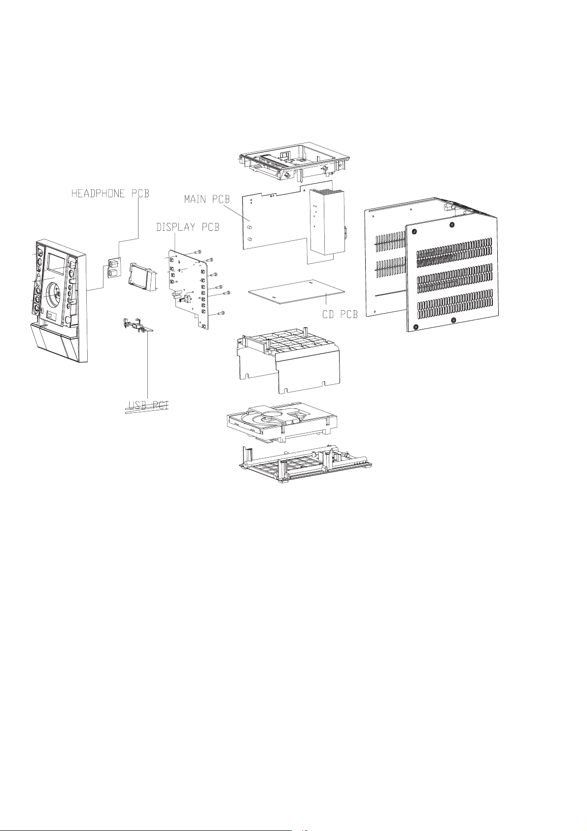
PCBS LOCATION
1-2
Page 3

SPECIFICATIONS
1-3
AMPLIFIER
Output power ........................................................................
............... 2 x 50 W RMS / 2 x100 W music power
Signal-to-noise ratio .......................... t 62 dBA (IEC)
Frequency response ......... 40 – 15000 Hz, ± 3 dB
Impedance loudspeakers ......................................... 6 :
Impedance headphones ........................................ 32 :
CD/MP3/WMA-CD PLAYER
Number of programmable tracks ......................... 20
Frequency range .................................. 20 – 20000 Hz
Signal-to-noise ratio ............................................ 75 dBA
Channel separation .......................... t 60 dB (1 kHz)
Total harmonic distortion ........................... < 0.003%
MPEG 1 Layer 3 (MP3-CD) .......... MPEG AUDIO
MP3-CD bit rate ....................................... 32-256 kbps
(128 kbps advised)
Sampling frequencies ....................... 32, 44.1, 48 kHz
USB PLAYER
USB ................................................................. 12 Mb/s, V1.1
......................................... support MP3 and WMA files
Number of albums/folders ................. maximum 99
Number of tracks/titles ...................... maximum 500
FM
FM wave range ................................... 87.5 – 108 MHz
Sensitivity at 75 :
– mono, 26 dB signal-to-noise ratio ............ 2.8 µV
– stereo, 46 dB signal-to-noise ratio ........ 61.4 µV
Selectivity ................................................................. t 28 dB
Total harmonic distor tion ..................................... d 5%
Frequency response ..... 63 – 12500 Hz (± 3 dB)
Signal-to-noise-ratio ...................................... t 50 dBA
SPEAKERS
2-way Bass reflex system
Dimensions (w x h x d) . 140 x 228 x 247 (mm)
GENERAL INFORMATION
AC Power ..................................... 220 – 230 V / 50 Hz
Dimensions (w x h x d) .. 152 x 228 x 273 (mm)
Weight (with/without speakers)
............................................................... approx. 6.2/3.65 kg
Eco Power Standby ............................................... < 1 W
Power consumption Standby ....................... < 12 W
Page 4
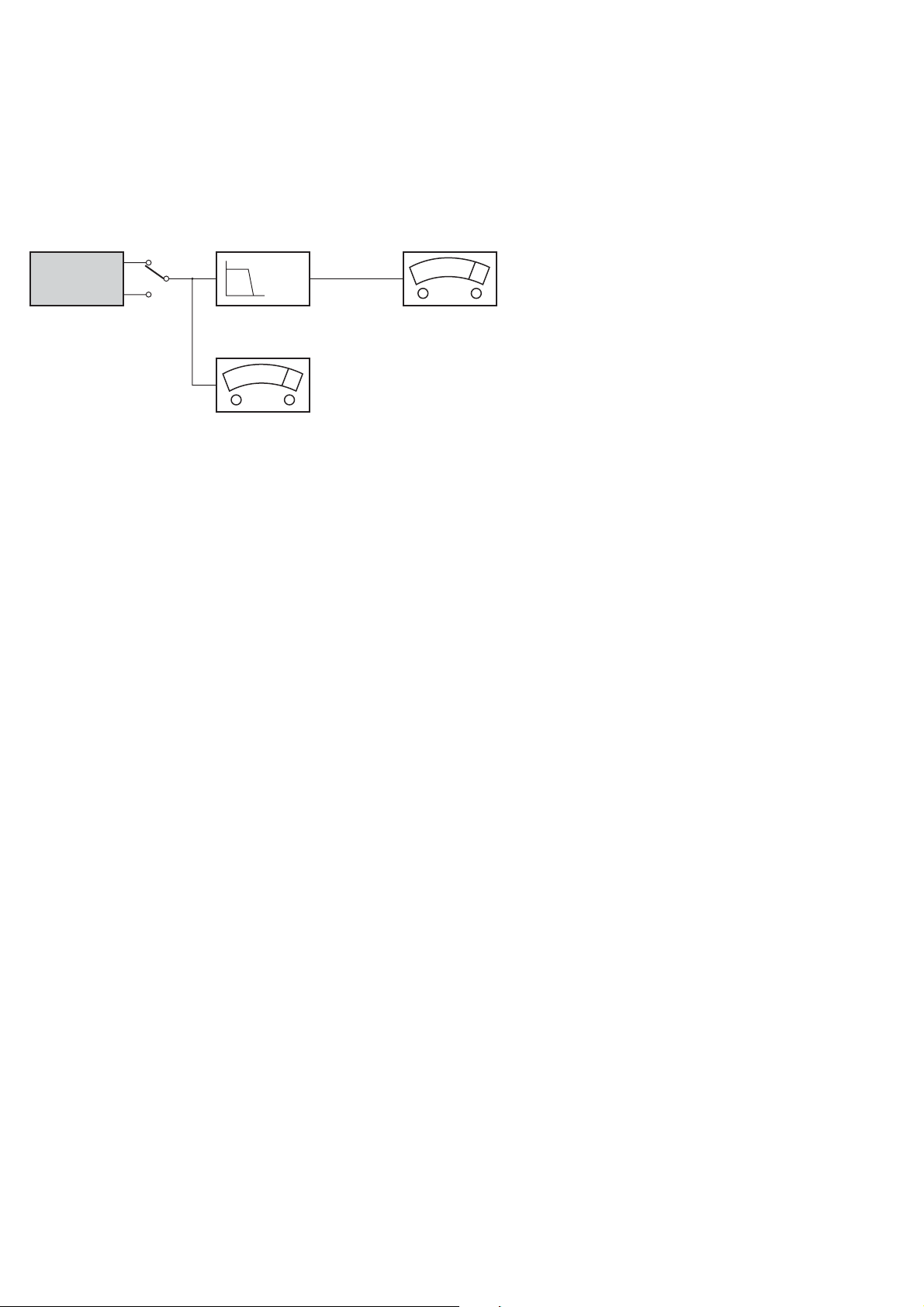
MEASUREMENT SETUP
CD
Use Audio Signal Disc SBC429 4822 397 30184 (replaces test disc 3)
L.P.F. = 13
th
order filter 4822 395 30204
1-4
DUT
Low pass filter 22kHz
L
R
S/N and distortion meter
e.g. Sound Technology ST1700B
LEVEL METER
e.g. Sennheiser UPM550
with FF-filter
Page 5
SERVICE AIDS
1-5
Service Tools:
Universal Torx driver holder .................................4822 395 91019
Torx bit T10 150mm ...........................................4822 395 50456
Torx driver set T6-T20 .........................................4822 395 50145
Torx driver T10 extended .....................................4822 395 50423
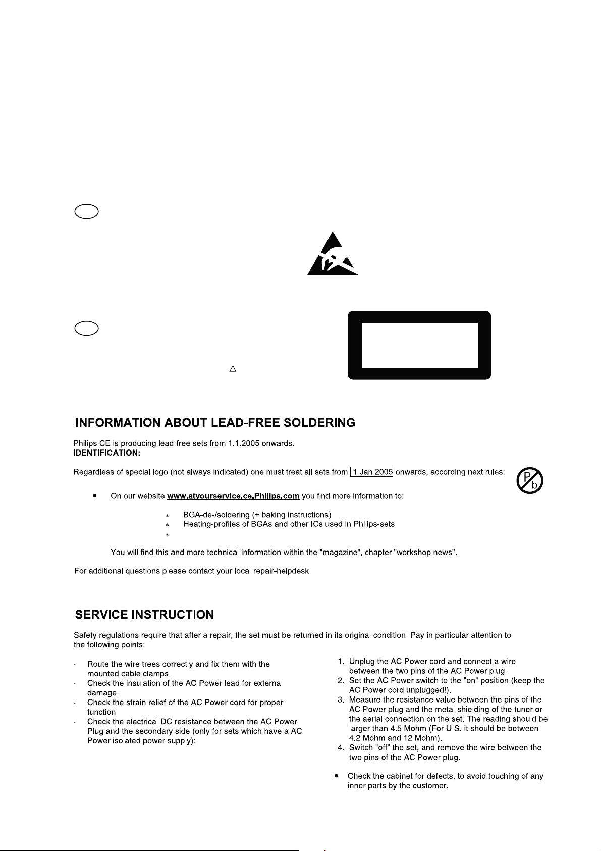
GB
All ICs and many other semi-conductors are
susceptible to electrostatic discharges (ESD).
Careless handling during repair can reduce life
drastically.
When repairing, make sure that you are
connected with the same potential as the mass
of the set via a wrist wrap with resistance.
Keep components and tools also at this
potential.
WARNING
GB
Safety regulations require that the set be restored to its original
condition and that parts which are identical with those specified,
be used
Safety components are marked by the symbol
!
.
Compact Disc:
SBC426/426A Test disc 5 + 5A ...........................4822 397 30096
SBC442 Audio Burn-in test disc 1kHz .................4822 397 30155
SBC429 Audio Signals disc .................................4822 397 30184
Dolby Pro-logic Test Disc ....................................4822 395 10216
ESD
CLASS 1
LASER PRODUCT
Lead free
Page 6
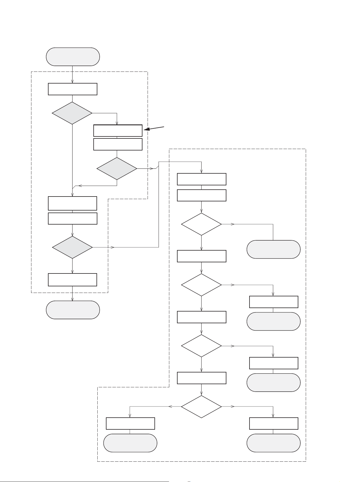
INSTRUCTIONS ON CD PLAYABILITY
Customer complaint
"CD related problem"
Set remains closed!
check playability
1
1-6
playability
ok ?
Y
Play a CD
for at least 10 minutes
check playability
playability
ok ?
Y
N
"fast" lens cleaning
check playability
playability
ok ?
N
3
For flap loaders (= access to CD drive possible)
cleaning method
4 is recommended
Standard repair procedure
N
Y
clean the lens
check playability
playability
ok ?
check "EYE-Pattern"
4
Y
N
5
return set
add Info for customer
"SET OK"
return set
1 - 7
For description - see following pages
2
replace Signal Processor
return set
EYE-Pattern
ok ?
Y
check Laser current
Laser current
ok ?
Y
check CD Drive offsets
Y
CD Drive offsets
ok ?
N
replace CD Drive
6
return set
N
replace CD Drive
7
return set
N
replace CD Drive
return set
Page 7
INSTRUCTIONS ON CD PLAYABILITY
1-7
1
PLAYABILITY CHECK
For sets which are compatible with CD-RW discs
use CD-RW Printed Audio Disc....................7104 099 96611
TR 3 (Fingerprint)
TR 8 (600µ Black dot) maximum at 01:00
• playback of these two tracks without audible disturbance
playing time for: Fingerprint ≥10seconds
Black dot from 00:50 to 01:10
• jump forward/backward (search) within a reasonable time
For all other sets
use CD-DA SBC 444A..................................4822 397 30245
TR 14 (600µ Black dot) maximum at 01:15
TR 19 (Fingerprint)
TR 10 (1000µ wedge)
• playback of all these tracks without audible disturbance
playing time for: 1000µ wedge ≥10seconds
Fingerprint ≥10seconds
Black dot from 01:05 to 01:25
• jump forward/backward (search) within a reasonable time
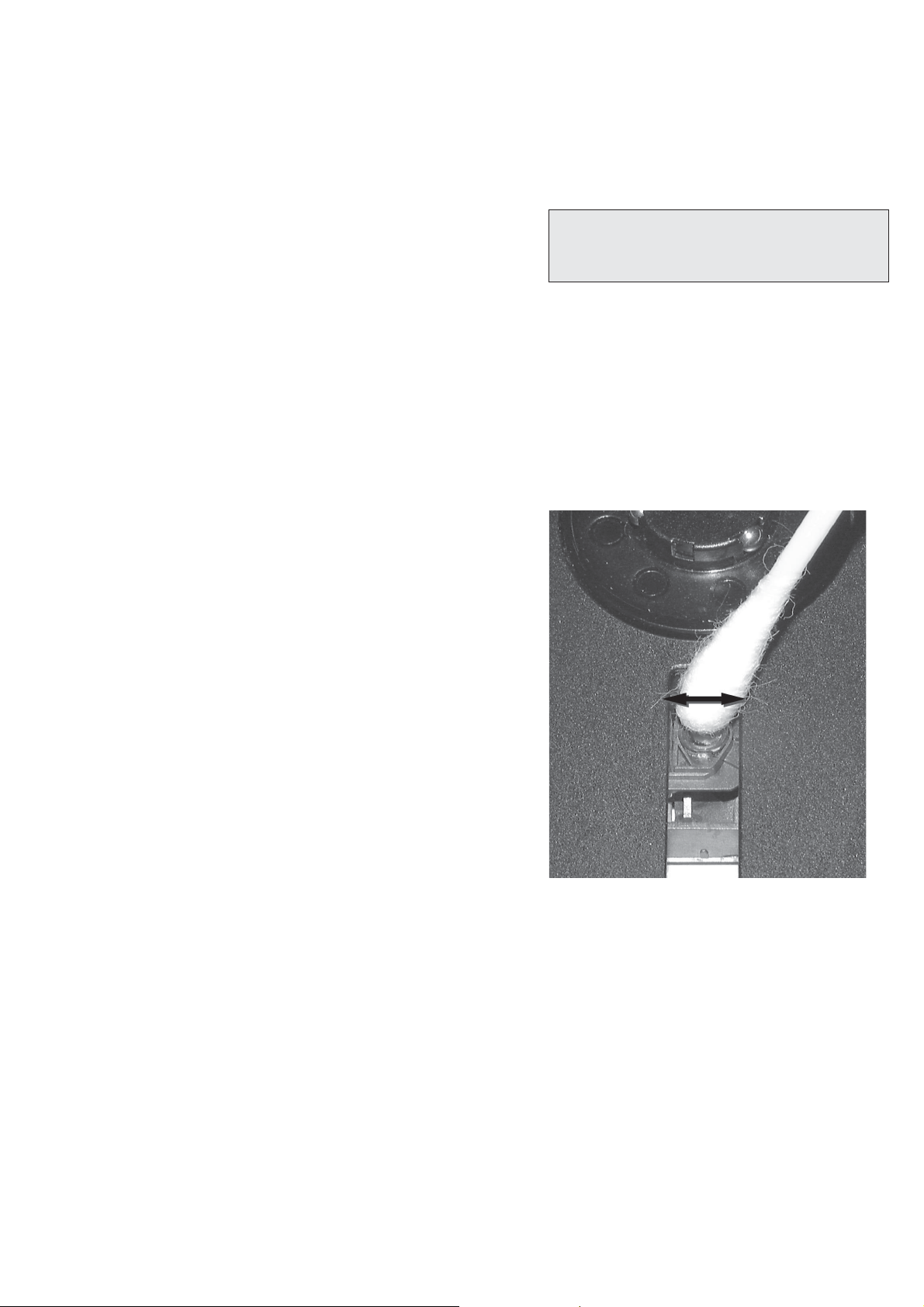
4
LIQUID LENS CLEANING
Before touching the lens it is advised to clean the
surface of the lens by blowing clean air over it.
This to avoid that little particles make scratches on
the lens.
Because the material of the lens is synthetic and coated
with a special anti-reflectivity layer, cleaning must be done
with a non-aggressive cleaning fluid. It is advised to use
“Cleaning Solvent B4-No2”, available with codenumber
4822 389 10026.
The actuator is a very precise mechanical component and
may not be damaged in order to guarantee its full function.
Clean the lens gently (don’t press too hard) with a soft and
clean cotton bud moistened with the special lens cleaner.
The direction of cleaning must be in the way as indicated in
the picture below.
2
CUSTOMER INFORMATION
It is proposed to add an addendum sheet to the set which
informs the customer that the set has been checked
carefully - but no fault was found.
The problem was obviously caused by a scratched, dirty or
copy-protected CD. In case problems remain, the customer
is requested to contact the workshop directly.
The lens cleaning (method 3) should be mentioned in the
addendum sheet.
The final wording in national language as well as the printing
is under responsibility of the Regional Service Organizations.
3
FAST LENS CLEANING (dry brush)
Use lens cleaning CD
SBC AC300...........................................9082 100 00043
Insert the lens cleaning CD, press PLAY and follow the
voice guide´s instructions on the CD.
Page 8
Sanyo DA12T3
CD Drive
A
A
F
C
B
E
C
D
E
VCC
B
VREF
F
D
9
10
11
12
13
14
15
16
1800
+5V_HF
VrefCD10
A
D
E
B
C
F
GND
8
E
D
A
B
C
F
Laser power control
100n
2878
470n
2876
3821
1R
1K
3823
2880
33p
+5V
BC807-40
7879
3817
47R
3820
4R7
47R
3819
1n
2879
2877
47u
1
8
4
7811-A
LM358D
3
2
10K
3822
47R
3818
2841
100n
47n
2869
+5V_HF
LASER DIODE
U >250mV
->Laser damaged !
4,6V
3V
3,3V
3,9V
2V
0,17V
0,17V
Sanyo
DA12T3
HF-Amplifier
D3
D2
D1
680R
3905
3903
3K3
BC847B
7877
47n
2818
1K5
3902
5
7
4
2
1
6
3
64
8
9
10
11
470R
3893
+3.3V
2K2
3908
10K
3923
BC847B
7878
BC847B
7876
4n7
2813
3896
100R
220u
2885
2881
560p
47n
2887
560R
3901
2883
470n
2817
4u7
3n3
2814
3898
220R
3895
27K
470n
2884
+3.3V
3909
820R
3907
100R
3920
33K
3897
2882
82p
3K3
3904
2K7
3899
3906
470R
+5V_HF
HFIN
VrefCD10
100p
28152816
22n
LDON
to 3826,3827
VREF GE
VDDA1
VRIN
VSSA1
ISLICE
LD
ON
D1
D2
D3
D4
HFIN
HFREF
IREF
CD_DA: 0V / CD_RW: 3V
Σ (A-D)
800mVpp
TB = 0.5µs/div
EYE-PATTERN
1,8V
1,2V
2,4V
2,6V
0,65V
INSTRUCTIONS ON CD PLAYABILITY
1-8
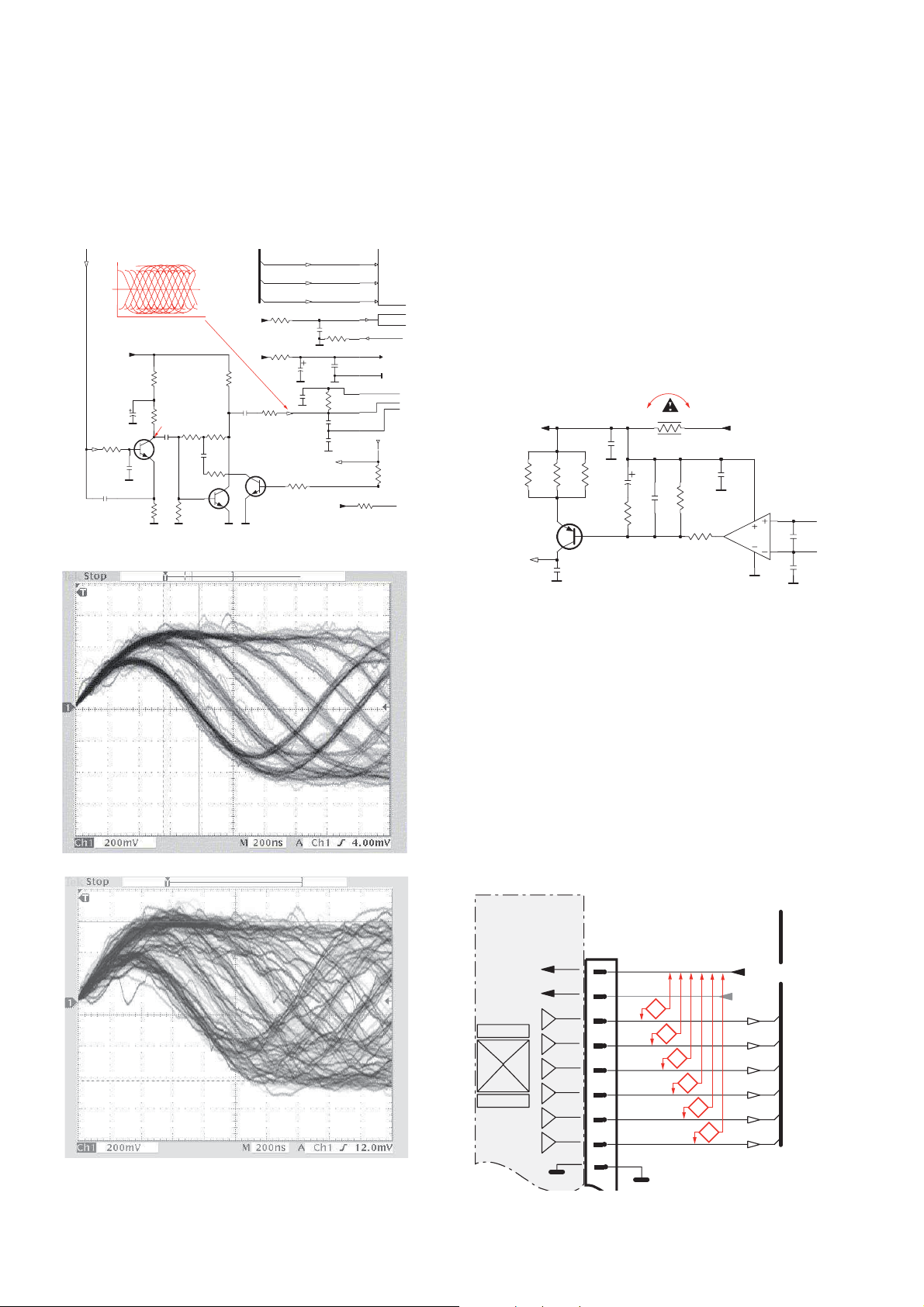
5
EYE-PATTERN SIGNAL – JITTER MEASUREMENT
Measure the signal on the input of the Signal processor
using an analog oscilloscope. Please find the exact
measuring point in your Service Manual.
See below examples of the signal. Amplitude should read at
least 700mVpp using SBC444A.
6
CD DRIVE – LASER CURRENT MEASUREMENT
The laser current can be measured as a voltage drop on a
resistor. The resistor is marked in every Service Manual.
The value depends on the type of CD drive.
typical value most probably defect
VAMxxxx : 150-230mV ≥350mV
MCDxx : 170-230mV ≥300mV
DA1x : 210-250mV ≥350mV
DA2x : 175-200mV ≥250mV
Use SBC444A (CD-DA) for measurement.
If the oscilloscope shows a signal like the ‘bad’ one, and/or
the amplitude decreases within 1 minute - the CD drive has
to be replaced.
good
bad
7
CD DRIVE – OFFSET MEASUREMENT
The photodiodes of the CD-drive may have an offset. These
offsets have to be compensated by the signal processor.
High offsets can lead to poor playability of some CDs
(skipping tracks).
To measure the offset values, start the Service Test
Program - section “Focus Test” without a CD.
The offsets can be measured with a DC Millivoltmeter
directly on the connector (see drawing below). Pin
numbering varies from drive to drive.
The values from diode A-D should read 0±10mV.
Diodes E and F are less critical.
If one of the offsets is higher than ±10mV the CD drive has
to be replaced. Otherwise replace the Signal Processor.
Page 9

SOFTWARE VERSION CHECKING
2-1
2-1
How to read software version,
1. Press and hold DISPLAY and SOURCE buttons then plug A/C to power on,
LCD Display shows existing software version "S 0.12".
2. During shows "S 0.12", press “STOP” button to show firmware version.
Page 10
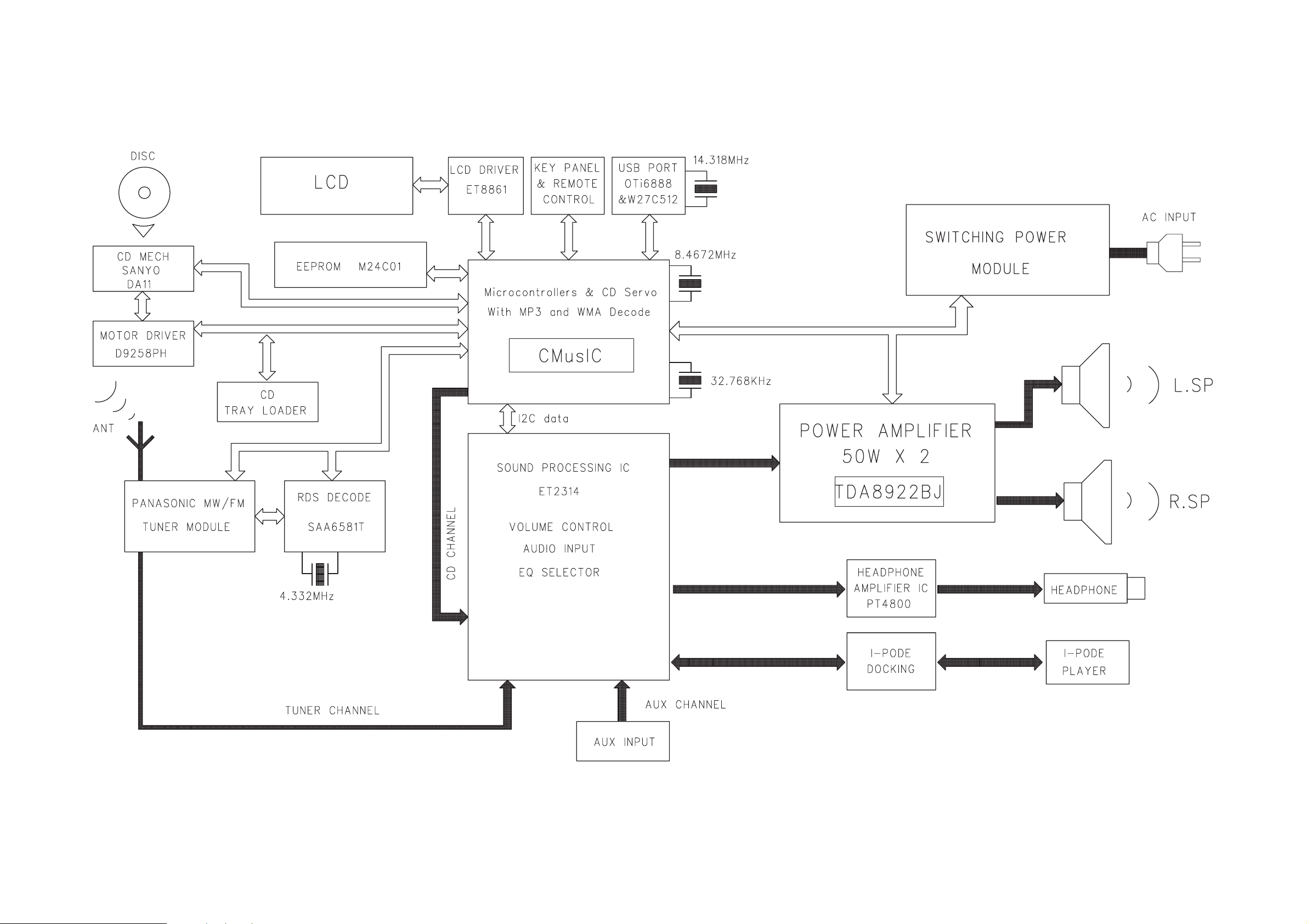
SET BLOCK DIAGRAM
3-1
3-1
Page 11

SET WIRING DIAGRAM
4-1
4-1
Page 12

5-1 5-1
MAIN BOARD
TABLE OF CONTENTS
Main PCB - Layout Top View ........................................... 5-2
Main PCB - Layout Bottom View .....................................5-3
Main PCB - Circuit Diagram Part1 ....................................5-4
Main PCB - Circuit Diagram Part2 ....................................5-5
Headphone & AUX PCB - Circuit Diagram .......................5-6
Page 13

5-2 5-2
PCB LAYOUT - MAIN BOARD (TOP VIEW)
Page 14

5-3
PCB LAYOUT - MAIN BOARD (BOTTOM VIEW)
5-3
Page 15

CIRCUIT DIAGRAM - MAIN BOARD
PART1
5-4
5-4
Page 16

CIRCUIT DIAGRAM - MAIN BOARD
PART2
5-5
5-5
Page 17

5-6
CIRCUIT DIAGRAM - HP & AUX BOARD
5-6
Page 18

6-1 6-1
FRONT(DISPLAY) & USB
JACK BOARD
TABLE OF CONTENTS
Display PCB - Layout Top View ....................................... 6-2
Display PCB - Layout Bottom View .................................6-3
Display PCB - Circuit Diagram .........................................6-4
USB PCB - Circuit Diagram ..............................................6-5
Page 19

6-2 6-2
PCB LAYOUT - DISPLAY BOARD (TOP VIEW)
Page 20

6-3
PCB LAYOUT - DISPLAY BOARD (BOTTOM VIEW)
6-3
Page 21

6-4
CIRCUIT DIAGRAM - FRONT(DISPLAY) BOARD
6-4
Page 22

CIRCUIT DIAGRAM - USB BOARD
6-5
6-5
Page 23

7-1
CMUSIC BOARD
7-1
TABLE OF CONTENTS
CMUSIC PCB - Layout Top View .....................................7-2
CMUSIC PCB - Layout Bottom View ................................7-3
CMUSIC PCB - Circuit Diagram ....................................... 7-4
Page 24

7-2
PCB LAYOUT - CMUSIC BOARD (TOP VIEW)
7-2
Page 25

7-3
PCB LAYOUT - CMUSIC BOARD (BOTTOM VIEW)
7-3
Page 26

CIRCUIT DIAGRAM - CMUSIC BOARD
CD & TUNER PART
7-4
7-4
Page 27

CIRCUIT DIAGRAM - CMUSIC BOARD
USB PART
7-5
7-5
Page 28

SET MECHANICAL EXPLODED VIEW
8-1
8-1
Page 29

8-2
MECHANICAL & ACCESSORIES PARTS LIST
1 996510004576 CD LOADER COVER
2 996510001086 CHROME RING-LOADER COVER
3 996510004572 DISPLAY LENS
4 996510004573 LEFT FRONT PANEL I 996510001913 IPOD HOLDER-60GB-VIDEO-INJ.
5
6
7 996510001448 STANDBY BOTTON LIGHT GUIDE L
8 996510004571 CONTROL KEY-DOCKING M
22
24 996510004581
25 996510004569
30 996510000868 CD DAMPER PINK 658F
31 996510004568 BOTTOM CABINET
35
37
38
39 996510001438 VOLUME KNOB RING
40
996510004567
996510004577
996510004566
996510004578
996510004570
996510004574
996510001082
FRONT CABINET J 996510001914 IPOD HOLDER-MINI-INJ.
CONTROL KEY SET - LEFT K 996510001915 IPOD HOLDER-NANO-INJ.
TOP CABINET N
F
G
H 996510001912 IPOD HOLDER-60GB-INJ.
OREVOC POT57540001569932
1
2
996510001099
996510001911
996510001916
996510001917
996510001918
994000005786
996510005461 BS POWER SUPPLY CORD
AM LOOP FRAME ASSY
IPOD HOLDER-40GB-INJ.
IPOD HOLDER-20GB-INJ.
IPOD HOLDER-30GB-PHOTO-INJ
IPOD HOLDER-30GB-VIDEO-INJ.
CD MECHANISM DA11VF(SANYO)
/12
1.83M /05
Note: Only these parts mentioned in the list are
normal service parts.
Page 30

D
D
D
D
D
8-3
ELECTRICAL PARTSLIST
C MUSIC BOAR
IC401 994000003199
IC901 996510004550 IC (PROGRAMMED) SAA7838H/N3 SW705 996500039269 TACT SWITCH
IC902
IC903
Q204 994000005729 TRANSISTOR KTA1273 TO-92L SW708 996500039269 TACT SWITCH
Q211 994000005729 TRANSISTOR KTA1273 TO-92L SW709
Q901 996510000378 TRANSISTOR BST50 SW710
Q909 996500039268 TRANSISTOR KTC-8050C
Q910 996500039268 TRANSISTOR KTC-8050C SW712 996500039269 TACT SWITCH
IC905 994000005751 I.C. 74HC4520DB SSOP16 SW713 996500039269 TACT SWITCH
IC906
IC907
IC908 996510001069 IC D6208 SOP8
L101 994000005754
Q204 994000005755
Q211 994000005755
Q909 996500039268
Q910 996500039268
U201
U202 996510000738 IC EPROM ICE27C512-70?PCW
X901
X902 994000003208 CRYSTAL 32.768KHZ 12.5PF -10P
Y1
ZD2001 994000005744 ZENER DIODE 5V1 1/2W
994000005753
994000003272
994000005749
994000005748
994000005747
994000005742
994000005741
FRONT & USB BOAR
CON102 996510001071 USB JACK 4P ANGLE TYPE
D101 996510001072 LED INDICATOR D3 CLEAR BLUE
D102 996510001072 LED INDICATOR D3 CLEAR BLUE
D103 996510001072 LED INDICATOR D3 CLEAR BLUE
EN701 996510004552 ENCODER E1211A3V1NE0054
FB701 996510001060 FER. BEAN SBK160808T-601Y-S
IC701 996510001064 IC ET8861S (FOR LCD DRIVER)
LCD701 996510001061 LCD DISPLAY GS-34301+HSC-A/P
LED701 996510000394 LED INDICATOR RED4.3X2.98MM
LED702 996510004553
LED703 996510004553 LED INDICATOR D3mm WHITE
LED704 996510004553 LED INDICATOR D3mm WHITE
LED705 996510001422 LED INDICATOR BLUE 33B4SCA01
LED706 996510001422 LED INDICATOR BLUE 33B4SCA01
LED707
RS701
SW701
SW702
SW703
996510001422
996510001070
996500039269
996500039269
996500039269
IC HEF4094BT SW704 996500039269 TACT SWITCH
I.C. D9258PH SW706 996500039269 TACT SWITCH
IC M24C01-RDW6T SW707 996500039269 TACT SWITCH
SW711 996500039269
I.C. 74HC4094DB SSOP16
I.C. 74HC02DB SSOP14
FIXED INDUCTOR 33UH-K
TRANSISTOR KTA1273 TO-92L
TRANSISTOR KTA1273 TO-92L
TRANSISTOR KTC-8050C
TRANSISTOR KTC-8050C
IC OTI6888-G LQFP-64
CRYSTAL 8.4672 MHZ 20PF
CRYSTAL 14.318 MHZ 20PF
LED INDICATOR D3mm WHITE Q214 994000005727 TRANSISTOR 2SB562C TO-92MOD
LED INDICATOR BLUE 33B4SCA01
INFRARED RECEIVER SM3385B
TACT SWITCH
TACT SWITCH
TACT SWITCH
ZD701 996510004551
HP901 994000003229 HEADPHONE JACK D3.5MM
HP902 996510001073 EARPHONE CKX3.5-19S (3PIN)
C319 996510004554 CBB CAP HMFS-5 0.47UF 63V
C320 996510004554 CBB CAP HMFS-5 0.47UF 63V
CN301 996510000380 PUSH TERMINAL JACK PST-418
CN401 996510001073 EARPHONE CKX3.5-19S (3PIN)
CN402 996510004561 MINI DIN JACK 9PINS
D201 996510001053 RECTIFIER DIODE RL201
IC201 996510001057 IC S1117-33PIC TO-220F-3SL
IC202 996510001058 IC S7806PI TO-220F
IC301 996510004564 POWER AMPLIFIER IC TDA8922BJ
IC401 996510004563 I.C. LM324DG SOIC-14
IC501 996510001056 IC ET2314
IC601
IC801 996510004562 I.C. D4558
IC802 996500039259 I.C. PT4800(L) DIP-8 PIN
Q203 994000001436 TRANSISTOR 2SB1566-F
Q205 996500039268 TRANSISTOR KTC-8050C
Q208 996500039268 TRANSISTOR KTC-8050C
Q401 994000005755 TRANSISTOR KTA1273 TO-92L
Q501
Q881 994000003206 TRANSISTOR 8550D
Y601 994000003209 CRYSTAL 4.332MHZ HC-49/S
ZD201 996510004555 DIODE 10V 1/2W TCLLZ10V LL34
ZD205 996510004558 DIODE 6V8 1/2W TCLLZ6V8 LL34
ZD206 996510004560 DIODE 9V1 1/2W TCLLZ9V1 LL34
ZD351 996510004557 DIODE 5V6 1/2W TCLLZ5V6 LL34
ZD401 996510004556 DIODE 5V1 1/2W TCLLZ5V1 LL34
FRONT & USB BOAR
996500039269
996500039269
TACT SWITCH
TACT SWITCH
TACT SWITCH
ZENER DIODE BZX384-C3V3
HEADPHONE BOAR
MAIN BOAR
994000003215 RDS IC SAA6581T
996500039268
TRANSISTOR KTC-8050C
Page 31

D
8-4
ELECTRICAL PARTSLIST
MAIN BOAR
ZD402 996510004556 DIODE 5V1 1/2W TCLLZ5V1 LL34
ZD405 996510004565 CHIP VARISTOR 14V 270PF
ZD406 996510004565 CHIP VARISTOR 14V 270PF
ZD407 996510004565 CHIP VARISTOR 14V 270PF
ZD408 996510004565 CHIP VARISTOR 14V 270PF
ZD501 996510004559 DIODE 8V2 1/2W TCLLZ8V2 LL34
Note: Only these parts mentioned in the list are
normal service parts.
Page 32

REVISION LIST
1.0 Manual 3141 785 31830
Initial Service Manual released.
1.1 Manual 3141 785 31831
In this version, version /05 added.
1) P8-2 Mechanical and Accessories Partslist updated.
9-1
 Loading...