

Page 1
Version 1.2
MCD708
© 3141 785 30732
Service Manual
DVD Micro System
all versions
Published by LX 0612 Service Audio Printed in The Netherlands Subject to modification
©
Copyright 2006 Philips Consumer Electronics B.V. Eindhoven, The Netherlands
All rights reserved. No part of this publication may be reproduced, stored in a retrieval
system or transmitted, in any form or by any means, electronic, mechanical, photocopying,
or otherwise without the prior permission of Philips.
Handling chip components ............................................................1-1
Information about lead-free soldering............................................1-2
Technical specification...................................................................2-1
Service tools..................................................................................2-1
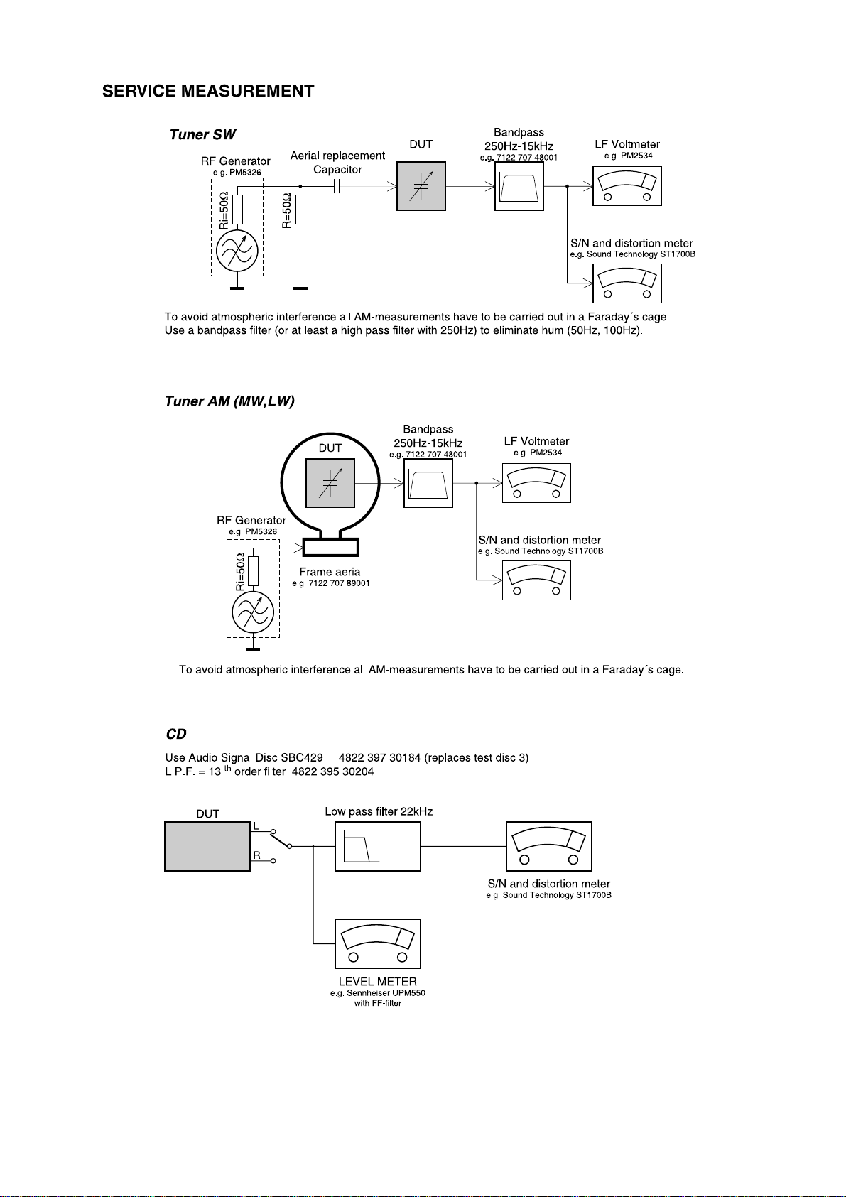
Service measurement setup..........................................................2-2
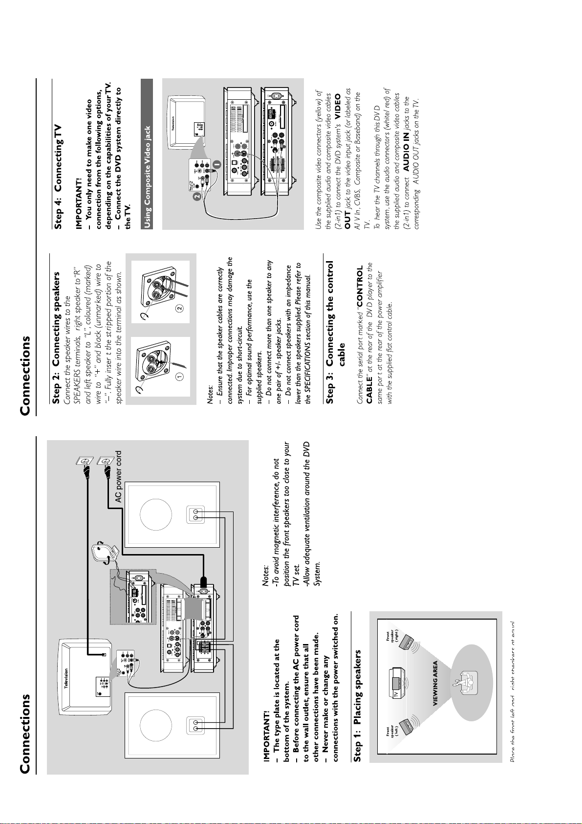
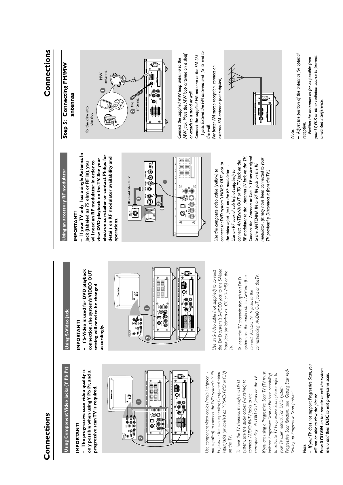
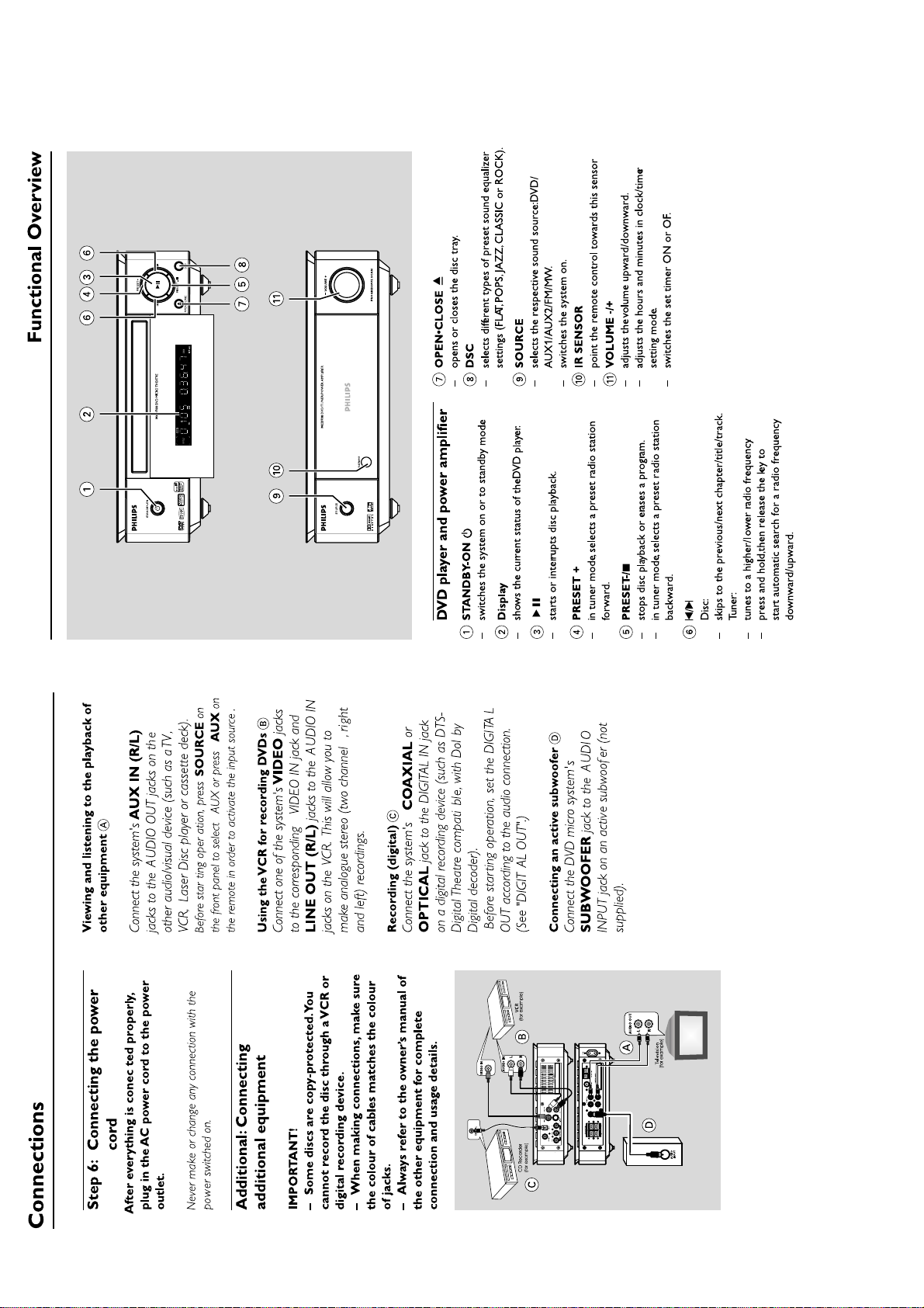
Connections and controls......................................................3-1...3-4
Disassembly diagram............................................................4-1...4-2
Software version and upgrading....................................................5-1
Set block diagram..........................................................................5-2
Set wiring diagram.........................................................................5-3
VFD BOARD
circuit diagram ..........................................................................6-1
layout diagram..........................................................................6-2
TUNER BOARD
circuit diagram ..........................................................................7-1
layout diagram..........................................................................7-2
layout diagram-amp box pcb assy............................................7-2
AMP BOARD
circuit diagram ..........................................................................8-1
layout diagram..........................................................................8-2
CPU BOARD
circuit diagram ..........................................................................9-1
layout diagram..........................................................................9-2
ALC VOLUME BOARD
circuit diagram ........................................................................10-1
layout diagram........................................................................10-2
DVD MPEG BOARD
circuit diagram..............................................................11-1...11-5
layout diagram........................................................................11-6
Exploded view diagram................................................................12-1
Mechanical partslist.....................................................................12-2
Electrical partslist...............................................................13-1...13-4
Revision list..................................................................................14-1
TABLE OF CONTENTS
CLASS 1
LASER PRODUCT
Page 2
1 - 1
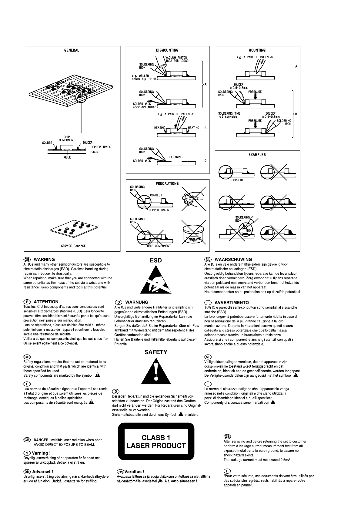
HANDLING CHIP COMPONENTS
Page 3
1 - 2
Page 4
2 - 1
Page 5
2 - 2
Page 6
3 - 1
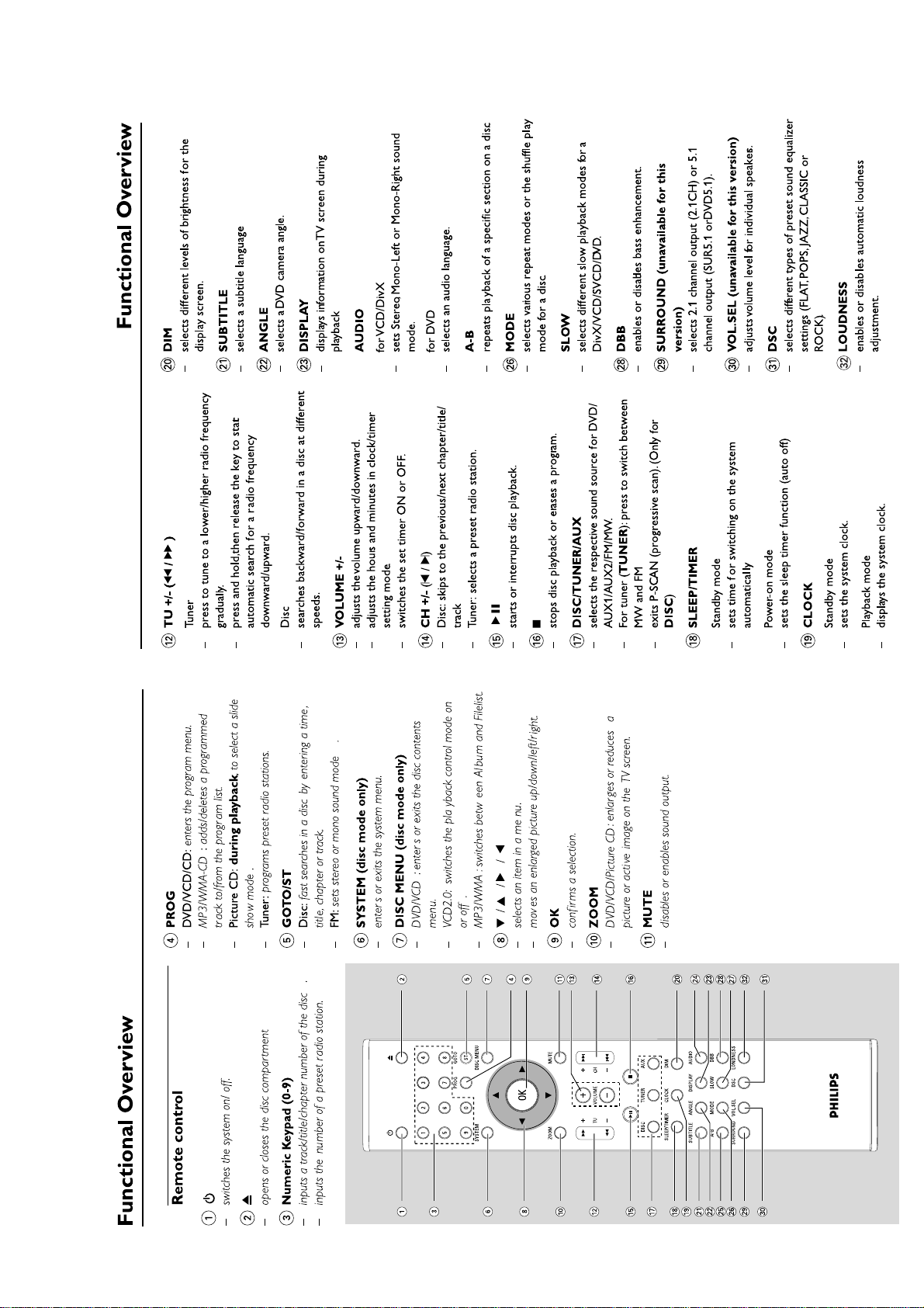
CONNECTION AND CONTROLS
Page 7
3 - 2
CONNECTION AND CONTROLS
Page 8
3 - 3
CONNECTION AND CONTROLS
Page 9
3 - 4
CONNECTION AND CONTROLS
Page 10
4 - 14 - 1
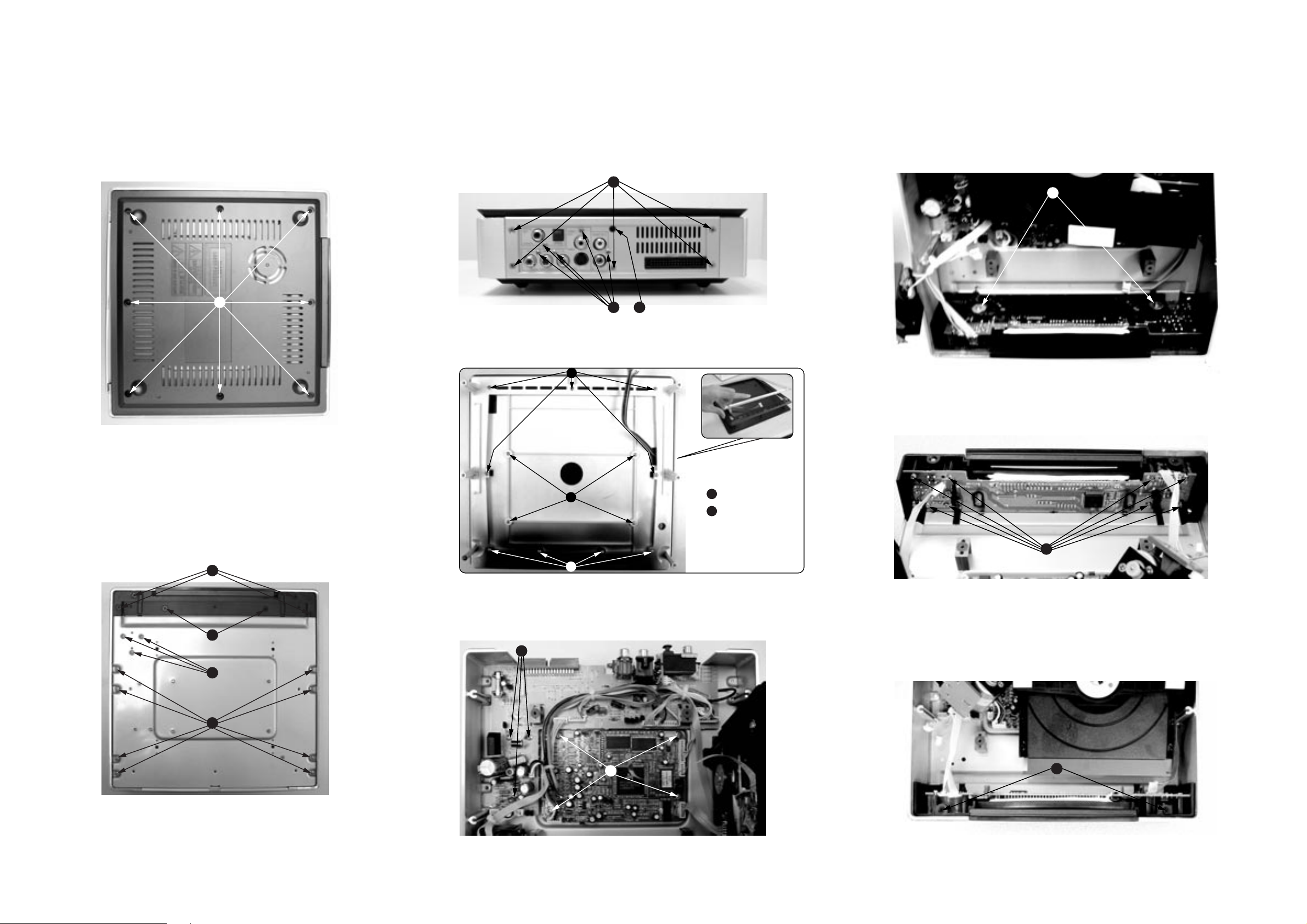
DISASSEMBLY DIAGRAM - DVD PART
A.Remove Bottom Cover
A1.remove screws M2.5x4(8pcs)
A
D.Remove Back Panel
D*remove screws T3x4(5pcs)and M3x10(5pcs)and T3x8(1pc)
D1
D2 D3
E. Remove Top Cover
E2
H.Remove Slid Plank
H
I.Remove VFD board assy
B*.remove screws M3x10(8pcs) and M3x8(3pcs)
C*.remove screws M3x8(4pcs) and T3x4(2pcs)
C1
C2
B2
B1
E1
E2
*M2.5x5
*M2.6x8
E1
E2
G. Remove DVD Rom and then remove DVD Decoder Card Assy
F
G
I
I.Remove Side metal Plate
J
Page 11
4 - 2 4 - 2
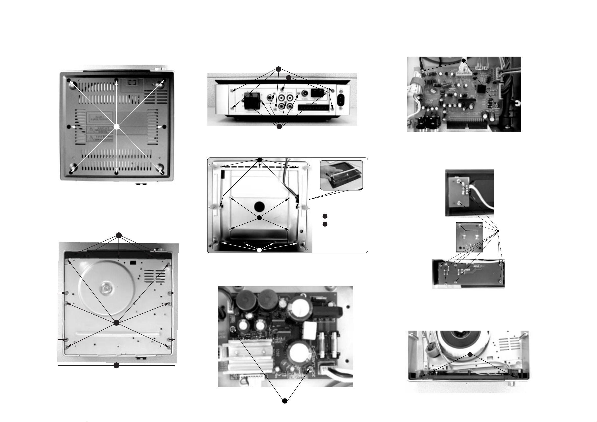
DISASSEMBLY DIAGRAM - AMP PART
A.Remove Bottom Cover
A1.remove screws M2.5x4(8pcs)
A
D.Remove Back Panel
D*remove screws T3x4(4pcs)and T3x8(2pcs)and M3x10(6pcs)
D1
D2
D3
E. Remove Top Cover
E2
G.Remove ALC Volume board assy
G
H.Remove AMP Front board assy
B*.remove screws M3x10(6pcs) and T3x10(4pcs)
C*.remove screws T3x4(5pcs)
C
B1
E1
E2
F. Remove AMP Board Assy
E1
E2
*M2.5x5
*M2.6x8
H
I.Remove Side metal Plate
B2
I
F
Page 12
5 - 1
5 - 1
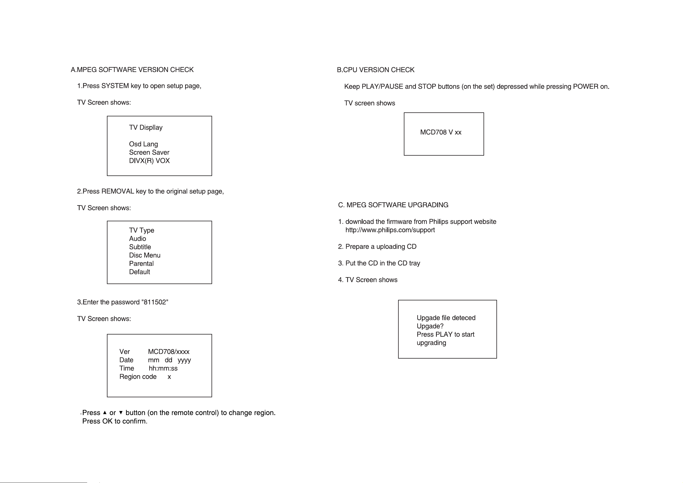
SOFTWARE VERSION AND UPGRADING
4
Page 13

5 - 25 - 2
SET BLOCK DIAGRAM
Page 14

5 - 3 5 - 3
SET WIRING DIAGRAM
Page 15

6 - 1 6 - 1
CIRCUIT DIAGRAM - VFD BOARD
Page 16

6 - 26 - 2
LAYOUT DIAGRAM - VFD BOARD
Page 17

7 - 17 - 1
CIRCUIT DIAGRAM - TUNER BOARD
TUNE1
KST-F404
1
ANT
FMFRONTEND
GND2GND3GND4VT
JACK1
FMRFGND
AMRFGND
TUNER1
FMANT
AMANT
CN3
2
1
2P
4
3
2
1
5
4
C8
104
T4
A9452/20382
VCC VCC
C3
104
1
16
2
3
CT1
11P
J2
000
J3
000
5B+6
OSC-OUT
C9
100uF
27
D3A
HN1V02H
IF-OUT
GND9GND
10
R8
2.2K
R9
100
+FM
R26
47
7
8
T5
44108
6
C13
103
C11
33pF
R6
330
34
2
1
R1
120
D2
BAS316
C21
1uF
3 6
22pF
D3B
C36
C37
560p
T104
5
R2
120
R5
330
R10
220
R15
0
R38
0
HN1V02H
C38
2pF
R20
22k
VCC1
RV1
100K
4
321 6
C6
331
RDSONLY
R36
33K
C1
10uF
C4
104
C10
100uF
R11
56K
R12
1K
C22
224
T6
20402
BIRDYFILTER
VCC1
R19
22K
C12
BC857C
33pF
BUFFERAMPLIFIER
Q4
10
11
1
2
3
4
5
6
7
8
9
R13
1K
C26
474
T1
11844/44023
R39
0
43
NC
C28
1uF
R28
820
MPX
C39
153
6
42
RF-GND2
C2
104
44
AGC
RIPPLE
AM-RF
FM-GND
RF-GND1
FM-OSC
AM-OSC
Vcc1
TUNE
VCO
AF-OUT
MPX-IN
LPF12MUTE13LEFT14RIGHT15PILFIL16IF-GND17FMDEM18AFC-19AFC+20FSI21VCC2
R27
2K2
C27
474
C20
222
41
AM-IF1-IN
R29
820
6
153
22n-USA22n-USA
40
C40
34
2
1
CF
10.7M
1
3
AM/FM
2
39
38
AM/FM
VSTABA
AM-MIXOUT
C31
C30
15pF
2.2uF
34
2
1
T7
511BE/43462
DISCRIMINATOR
1
37
C32
470n
C42
224
C43
224
FM-IF1-IN
36
C33
82pF
C7
104
AM-IF2
100uF
C41
R17
3
2
34
35
FM-IF2-IN
FM-IF2
VSTABB
AM-AFC
WRITE-EN
DATA
CLOCK
DGND
XTAL
MO/ST
VDD
22
VCC2
VCC
1M
1
10.7M
P1
P0
R41
100
CF2
IC1
TEA5762
C23
224
R42
4.7K
Q1
9014
R46
1K
T3
11845/20591
34
2
102
C15
12P
C16
221
R3
120
C34
223
C29
1uF
Q2
BC857B
224
224
8.2V
6
6
R37
0
P1
P0
C19
222
R4
120
R30
150
R31
68K
C17
221
C35
R25
47K
R18
R21
BC547C
22K
470
R22 470
C18
221
Q3
22uF
R40
0
R24
47K
R33
5K6
R34
47K
R32
10K
R7
330
DZ1
R35
22
AM/FM
ENABLE/MPX
DATA
CLOCK
ST/NO
R23
470
VCC
RIGHT
SGND
BZX384-C11
R44
000
LEFT
MPX
R45
000
CN1
1
2
3
4
CN2
1
2
3
4
5
4P
5P
1
T2
11845/20591
34
2
1
33
32
31
30
29
28
27
26
X1
25
VCC1
VCC2
VDD
R16
1M
C5
104
75K
24
23
R14
150K
VDD
7.8V
11V
8.2V
8.9V
+FM
R43
4.7K
R47
1K
Q5
9014
C14
C24
C25
Page 18

7 - 2 7 - 2
LAYOUT DIAGRAM - TUNER BOARD
LAYOUT DIAGRAM -AMP BOX
PCB ASSY
ONLY FOR -/12
Page 19

8 - 18 - 1
CIRCUIT DIAGRAM - AMP BOARD
Page 20

8 - 2 8 - 2
LAYOUT DIAGRAM - AMP BOARD
Page 21

9 - 1
9 - 1
CIRCUIT DIAGRAM - CPU BOARD
Q
8050
Q207
8050
Q209
8050
Q203
R226
8050
R227
204
1K
1
2
3
4
5
6
7
CN201
5
4
3
2
1
CN209
2
1
R248
2.2K
Q206
8550
R225
2.2K
08
Q2
C201
8550
100UF/16V
5P
Q201
8550
R221
R220
2.2K
A5V
2.2K
R216
10K
L-OUT
R-OUT
R217
10K
Q202
8550
M1+
M1OPEN-SW
D-GND
CLOSE-SW
M+
M-
2P
RCA-2P
RCA204
3
2
1
LED201
LED(BLUE)
LED202
BLUE)
LED(
LED2
LED(BLUE)
LED204
LED(BLUE)
LED205
LED206
1
1
1
03
1
1
1
CN17
2P/2.0
2
2
2
2
2
LED(BLUE)
2
LED(BLUE)
R247
2.2K
R246
2.2K
A5
1K
M-CLOSE
M-OPEN
V
M-UP
M-DOW
N
7
6
5
4
3
2
1
C211
300P
KEY
LED
M-UP
M-DOW
DS-STB1
DS-DAT
DS-CL
REM
RO
ROT-B
R223
10K
V
A5
OPEN-SW
CLOSE-SW
LED1
LED2
LED3
LED4
LED5
6
LED
COM
2P/2.0
CN208
T-A
680
680
680
680
680
680
C203
300P
K
N
R224
10K
4148
M-CLOSE
M-OPEN
R211
R202
C219
103P
MUTE
R204
R205
R206
R207
R208
R203
D211
R215
10K
R212
100
R251 100
10K
10K
C220
103P
C206
Q210
8050
100U
C137
4.7uF
R155
2.2K
F/16V
R210
10K
C139
4.7uF
R161
2.2K
CN202
7P/2.0
+12V
C207
C208
C210
1
DS-STB1
R233
10K
FERQ HOP
300P
300P
300P
2
DS-DAT
DS-CLK
D209
3
4
D-GND
4148
A5V
5
34
35
36
37
38
39
40
41
42
43
44
LED
8P/2.0
CN206
24C01
5
6
7
8
R229
22K
C
30P
KEY
IC202
SDA
SCL
TEST
Vdd
R284
22
21
20
19
18
17
16
15
14
13
12
C225
47UF/10V
224
LED
C242
300P
C243
300P
C214
300P
C244
300P
C245
300P
C246
300P
C247
300P
240
C
300P
C268
300P
GND
10K
C226
A2
A1
A0
D207
104P
R285
4148
C227
10K
10UF/10V
C267
104P
10K
R286
R230
4
3
2
1
R231
R287
1K
C228
2.2UF/
100UF/10V
C229
560P
C253
1K
1K
10V
IC207
7805
S-IN
RD
PLLCE
C230
330P
1
2
3
4
5
6
7
JP203
LK
PLLDATA
PLLC
11
12
13
14
15
16
17
18
19
20
C202
102P
QUAL
RDDA
EF
VR
OSCOUT
MPX
OSEL
D
GN
ARI
FILOUT8FSEL
IC204
TD2579
OUT
GND
IN
C254
104P
0.1 1/4W
RDCL
T57
IN
OSC
Vs
EXRES
TM
220UF/10V
C255
C250
104P
C252
268
R
1000U
SDA
R281
100
LED
M-UP
DOWN
M-
DS-STB1
DS-DAT
DS-CLK
REMTOE
ROT-A
ROT-B
M+
M-
E
SCL
SUR-MUT
R259100
R280
100
Y
Q HOP
STANDB
FER
R260100
R256100
33
M-OPEN
OPEN-SW
1
MUTE
R262100
Y
STANDB
32
31
CLOSE
M-
KEY
3
2
L203
LLCE
P
R264100
R261
100
MUTE
30
STANDBY
TMS
RDS-IN
PLLDATAPLLC LK
R263100
-MUTE
SUR
ST/TUNED
29
MUTE
SUR-MUTE
Vdd
CLOSE-SW4DVD-
5
H
100U
R278
100
WER
ECO-PO
D205
4148
27
28
4052-A
Vss
6
ROT-B
SDA
26
ST/TUNED
XT-OUT7XT-IN
8
X201
4.19MHz
C221
30P
O-POWER
/TUNED
ST
EC
R279100
R2830
SCL
25
SDA
9
TUN-ON
24
SCL
TUN-ON
DVD-CLK
TEST
X-IN
10
C222
30P
T-A
RO
R2820
R266100
4.7K
R214
R213
68K
23
PLL-CE
PLL-CL
DA
PLL-
RDS-Q
RDS-SDA
RDS-SCL
DVD-STB
DVDDVD-DO
DVD-ON
RESET
X-OUT
203
IC
2SC9228
11
R228
3.3K
C223
30P
REM
TUN-ON
R267100
DI
X202
32.768KHz
ECO .VCC
-30V
D-GND
VF2
VF1
-24V
100
R269
R270
100
IC201TM58P20
22UH
DZ201
3V3
D206
IN60
REM
16
15
14
13
12
11
10
9
L205
2.7K
F/10V
D201
D202
R253
R252
1K
4001
GND
D-
R277
390
R271
15/0.
1
2
3
DVD IR
DVD STB
10
9
8
7
6
5
4
3
2
1
C232
104P
L216
220UH
R254
4001
470UF/25V
C266
5
4
5
LK
DVD C
DVD-TMS
DVD DATA
2.2K
R232
2
D210
5822
471/2W
R276
10K
R273
2201/
6
JACK202
RCA3P
1
5
4
326
1T
1
2
3
4
5
6
7
JACK4
S-VIDEO
291
R29210K
R
R290
10K
10K
288
R
1K
R289
1K
DVD ON
4.33MHz
X203
C233
C234
82P
47P
+12V
D5V(CD(8V)
R258
Vi
5
Q205
9014
28V
ON
10K
1
R255
47K
F3.15AL250V
F201
JP204
104
C263
IC208
2576
LM
Vo
GND
Vref
4
3
C213
104P
2W
DZ202
3300UF/25V
R257
4.7K
C
220/35V
+
AC
AC
-
KBL406
C259
C260
104P
264
1T
1T
1T
1T
1T
1T
3P
CN211
R1301
100
C1302
104P
L1301
1
2
3
4
5P
CN204
201
BD
AC1
AC2
330P
C1303
1T
1
JACK2 01
OP
L215
L214
L213
L212
L211
L210
L209
1
SP
100
2
TICL1
3
+5V
1303
R
3
BLUE
GREEN
RED
GND2
CVBS
SY
SC
SP
+5V
2
2
GND
4
D-GND1
CN205
10P/2.0
1
3
3P
CN1
100
R1302
R1304
33
5
1T
C1301
L208
1
2
3
4
5
6
7
8
9
10
104P
9P/2.0
CN2
FL
D-MUTE
GND
07
8
9
FR
11
12
13
14
15
16
17
18
19
20
21
22
23
24
25
26
27
28
29
30
31
32
33
1
2
3
4
5
6
7
34
CN109
34P
6
7
8
9
10
1
2
3
4
5
CN203
3P/2.0
1
2
3
Page 22

9 - 2
9 - 2
LAYOUT DIAGRAM - CPU BOARD
Page 23

10 - 1 10 - 1
CIRCUIT DIAGRAM - ALC VOLUME BOARD
Page 24

10 - 2
10 - 2
LAYOUT DIAGRAM - ALC VOLUME BOARD
Page 25

11 - 1
11 - 1
CIRCUIT DIAGRAM - DVD MPEG BOARD
MPEG board is not repaired,program for referrence only.
[ 1 ]
[ 1 ]
[ 1 ]
[ 1 ]
[ 1,2,3,5 ]
[ 1 ]
[ 1,2 ]
[ 2 ]
[ 2 ]
[ 2 ]
[ 2 ]
[ 2 ]
ACLK
ALRCK
ABCK
ASDAT0
ASDAT1
ASDAT2
TP66
TP65
TP64
TP63
+12V
-12V
+12V1
DV33[ 1 ]
VCC
VCC_AUDIO[ 1 ]
GND
MIC1
MIC_EN
ASPDIF
ASDAT[0..2][ 2 ]
ACLK
ABCK
ALRCK[ 2 ]
MUTE_DAC
RESET#[ 2 ]
ML[ 4 ]
MR[ 4 ]
DEMP[ 2 ]
AMDAT
REST_CS[ 2 ]
SCL[ 2,3 ]
SDA[ 2,3 ]
VSCK[ 2 ]
VSDA[ 2 ]
FAN[ 2 ]
R138 33
R139 33
R142 33
R143 33
R144 33
R145 33
SACLK
SBCLK
SLRCK
SDAT0
SDAT1
SDAT2
GND
4
+12V
ASDAT[0..2]
MUTE_DAC
RESET#
ML
MR
AMDAT
REST_CS
SCL
SDA
VSCK
VSDA
FAN
MIC2
GND
R176
0
+12V
-12V
+12V1
DV33
VCC
VCC_AUDIO
GND
MIC1
MIC_EN
ASPDIF
ACLK
ABCK
ALRCK
DEMP
SACLK
SLRCK
SBCLK
SDAT0
SDAT1
SDAT2
J2
1
2
3
4
4x1 W/HOUSING
DIP4/W/H/P2.0
FAN
J21
TJC3-8A
1
2
3
4
5
6
7
8
9
10
GND
A_D5V
A_D5V
A_D5V
SDA
GND
GND
SCL
C45
R212
NC/10k
A_D5V
+
CE11
0.1uF
47uF/16V
R211 OPEN
R210 0
R80
R209 OPEN
R83 0
R20 0
R208 0
R95 OPEN
Q34
NC/9014,SMD
VCC
VCC_AUDIO
SACLK
SBCLK
AMDAT
VCC_AUDIO
SLRCK
1:D/ACE2746(U24)
R128,R210,R145,R142,R204,R205,R206,R207,R208,CE71,CE46(OPEN)R209=0,R129=10,R198=R199=33,CE40=100uF/10V
2:D/ADA1196/WM8746(U24)
R209,R142,R198,R199,R129,R207,R208,CE71,CE46(OPEN),R128=10
L1
FB
A_D5V
SACLK
SBCLK
SLRCK
SDAT0
SDAT1
SDAT2
MODE
R12 0
0
U18
1
VL
2
MCLK
3
SCLK
4
SDATA
5
VA
6
GND
7
LRCK
8 9
DIV DIF
NC/CS5333
U10
WM8746/DA1196
1
DVDD
2
MCLK
3
BCLK
4
LRCK
5
DIN0
6
DIN1
7
DIN2
8
MODE
9
MUTE
10
LRCIN2
11
DGND
12
ML/I2S
13
MC/IWL
14 15
MD/DM AVDD2
R_GND
RST
VQ
LIN
RIN
FIL+
TST
AVDD1
OUT0R
OUT0L
AGND2
OUT1R
OUT1L
AGND1
OUT2R
OUT2L
GR0
GR1
GR2
CAP
16
15
14
13
12
11
10
I2SFORMAT
28
27
26
25
24
23
22
21
20
19
18
17
16
4
L_IN
R_IN
VCC_AUDIO
+
+
C21
CE55
1U
1U
+12V
CB78
0.1uF
R210=R145=R204=R205=R206=0,CE40=10uF/16V
DAC_MR
DAC_ML
DAC_SR
DAC_SL
DAC_LFE
DAC_CENT
CAP
CE48
+
CB75
0.1uF
100uF/16V
HARDWAREMODE
MIC2
R93
NC/470
J22
1
2
NC/2.54 mm TJC3-2
R213
NC/4k7
R214
NC/4K7
VCC
Q35
NC/9015,SMD
+
NC/10u/16V
CE59
TP81
TP82
CE5
+
OPEN/10uF/16V
FAN
DV33
R118
OPEN/4.7k
MIC_L
C60 2200pF
MIC_R
C62
C64 2200pF
C66
2200pF
R112
OPEN/1k
VREF
VREF
2200pF
VREF
VREF
C68
2200pF
VREF
C72 2200pF
VREF
1
R110
20k
R116
5.1k
10k
R193
R123
20k
R128
5.1k
10k
R194
R132
20k
R136
5.1k
3.9k
R198
R146
20k
5.1k
R148
10k
R197
R152
20k
R154
5.1k
10k
R196
R158
20k
R164
5.1k
10k
R195
Q18
OPEN/2N3904
SOT23
2 3
C59 220pF
GND
U13A
-
2
+
3
NJM4558 OPA
8 4
+12V
C61 220pF
GND
U13B
-
6
+
5
NJM4558 OPA
8 4
+12V
C63 220pF
GND
U15A
-
2
+
3
NJM4558 OPA
8 4
+12V
C65 220pF
GND
-
6
+
5
NJM4558 OPA
8 4
+12V
C67 220pF
GND
-
2
+
3
NJM4558 OPA
8 4
C69 220pF
GND
-
6
+
5
NJM4558 OPA
8 4
+12V
1
7
1
U15B
7
U16A
1
+12V
U16B
7
CE31
OPEN/10uF/16V
CE57
100uF/16V
ASPDIF
MIC_L
MIC_R
+
+
+
+
+
CE40
10uF/10V
CE44
10uF/10V
CE46
10uF/10V
CE49
10uF/10V
+
CE51
10uF/10V
CE53
10uF/10V
+12V
R115
10k
R127
10k
R135
10k
R147
10k
R153
10k
R163
10k
MIC_L
DAC_ML
MIC_R
DAC_MR
DAC_SL
DAC_SR
DAC_CENT
DAC_LFE
TP78
TP45
TP42
TP36
TP77
TP46
TP44
TP37
TP35
G/Y
B/U
R/V
MUTE_DAC
GND
ML
MR
GND
SR
SL
SUB
CENT
LIN
RIN
G/Y
B/U [ 4 ]
R/V
J20
1
2
3
4
5
6
7
8
9
10
11
HEADER 11
[ 4 ]
[ 4 ]
R204
N2
ML
MR
SL
SR
CENT
SUB
R137
100
VREF
R117
100
C97 100pF
N1
R129
100
C98 100pF
N6
C99 100pF
N5
R149
100
C100 100pF
N4
R155
100
100pF
N3
R165
100
C102 100pF
R200
10k
R199
10k
OPEN/0
R206
OPEN/0
R205
OPEN/0
R202
OPEN/0
R201
OPEN/0
C101
R203
OPEN/0
R85
OPEN/18k
R89
OPEN/18k
R119
47K
R131
47k
R141
47K
R151
47k
R157
47k
R167
47k
+
+
Page 26

11 - 2 11 - 2
CIRCUIT DIAGRAM - DVD MPEG BOARD
MPEG board is not repaired,program for referrence only.
+5VV
R77
NC
C48
NC
C52
NC
6
+5VV
R86
NC
5
Y1
R73
NC
2
C
13
E
B
2N3904
Y2
R81
NC
C92
NC
C91
NC
L28
NC
L32
NC
Q6
2907
Q8
2907
Y[1..6]
VSYNC#
+5VV
R97
75/DIP
R/V
C58
47p
C50
47p
6
75/DIP
SY
C86
NC
SC
C85
NC
Y6
150,1%
Y4
150,1%
R94
R75
C89
47P
C87
47P
L35
1.8uH,DIP
L29
1.8uH,DIP
R78
+5VV
Q13
2907
Q7
2907
G/Y
C81
NC
C83
NC
HSYNC#
ML
MR
G/Y
B/U
R/V
RESET#
GND
VCC
+12V
A21
A20
Y[1..6] [ 2 ]
VSYNC# [ 2 ]
HSYNC# [ 2 ]
ML [ 5 ]
MR [ 5 ]
G/Y
B/U [ 5 ]
R/V
VCC [ 1 ]
+12V [ 1 ]
[ 5 ]
[ 5 ]
RESET# [ 2 ]
[ 1 ]
GND
A21 [ 2 ]
A20 [ 2 ]
+5VV
+5VV
R92
75/DIP
CVBS_ST
Y3
R91
150,1%
C90
47P
L34
1.8uH,DIP
C56
47p
Q33
2907
C110
NC
Y5
150,1%
R84
C88
47P
L33
1.8uH,DIP
C54
47p
R87
75/DIP
B/U
5
2907
Q10
C82
NC
SCARTCONTROL
SCARTCONNECTOR
HSYNC#
TP31
TP30
VCC
TP22
TP21
TP19
TP17
TP33
TP49
TP4
TP16
SC
CVBS_ST
R/V
B/U
RGB/CVBS#
ML
TP20
TP18
TP32
TP38
TP1
TP6
VSYNC#
TP24
ASPDIF
SY
G/Y
ASPECT
TP5
MR
J17
1
2
3
4
5
6
7
8
9
10
11
12
1
13
14
Pitch=2.0m/m
15
16
17
18
SCART, 11P, PITCH=2.0M/M
+12V
VCC
DV33
R60
10K
R106
OPEN(0)
1
R2
2 3
10k
Q31
2N3904
R124
|
V
RGB_SWITCH[ 2 ]
0(OPEN)
DV33
R71
4.7k
[ 2 ]
A20
R98
680
R101
2.2k
1
RGB-S
R107 1k
R99
1k
Q14
2N3904
2 3
A20
[ 2 ]
Q16
3906
2 3
1
C
BE
3904/ 3906
R102
A21
2.2k
CB71
0.1uf
1
ASPECT
R100
75
Q15
2N3904
2 3
RGB/CVBS#
Page 27

11 - 3 11 - 3
CIRCUIT DIAGRAM - DVD MPEG BOARD
MPEG board is not repaired,program for referrence only.
U7
MA0
MA1 MA1
MA2
MA3
MA4
MA5
MA6
MA7
MA8
MA9
MA10
DBA0
SDCLK
SDCKE
DCS#
DRAS#
DCAS#
DWE#
DQM0
DQM1
SD33
R55 R
21
A0
22
A1
23
A2
24
A3
27
A4
28
A5
29
A6
30
A7
31
A8
32
A9
20
A10
19
BA/A11
35
CLK
34
CKE
18
CS
17
RAS
16
CAS
15
WE
36
DQMHNCVCCQ
33
NC
37
26
VSS
50
VSS
R54 R
DQ0
DQ1
DQ2
DQ3
DQ4
DQ5
DQ6
DQ7
DQ8
DQ9
DQ10
DQ11
DQ12
DQ13
DQ14
DQ15
VCC
VCC
VCCQ
VCCQDQML
VCCQ
VSSQ
VSSQ
VSSQ
VSSQ
ESMT M12L16161A-?
TMS
TDI
DQ7
2
DQ6
3
DQ5
5
DQ4
6
DQ3
8
DQ2
9
DQ1
11
DQ0
12
DQ8
39
DQ9
40
DQ10
42
DQ11
43
DQ12
45
DQ13
46
DQ14
48
DQ15
49
SD33 SD33
1
25
7
1314
38
44
4
10
41
47
MA0
MA1
MA2
MA3
MA4
MA5
MA6
MA7
MA8
MA9
MA10
MA11
DBA0
DBA1
SDCLK DQ15
SDCKE
DCS#
DRAS#
DCAS#
DWE#
DQM0
DQM1
23
24
25
26
29
30
31
32
33
34
22
35
20
21
38
37
19
18
17
16
15
39
36
40
54
41
28
MA0
MA2
MA3
MA4
MA5
MA6
MA7
MA8
MA9
MA10
DBA0
SDCLK
SDCKE
DBA1
DRAS#
DCAS#
DWE#
DQM0
DQM1
U9
A0
A1
A2
A3
A4
A5
A6
A7
A8
A9
A10/AP
A11
BA0/A13
BA1/A12
CLK
CKE
CS
RAS
CAS
WE
DQML
DQMH
NC
NC
VSS
VSS
VSS
HY57V641620HG-SDRAM 64M
U8
21
A0
22
A1
23
A2
24
A3
27
A4
28
A5
29
A6
30
A7
31
A8
32
A9
20
A10
19
BA/A11
35
CLK
34
CKE
18
CS
17
RAS
16
CAS
15
WE
36
DQMHNCVCCQ
33
NC
37
26
VSS
50
VSS
ESMT M12L16161A-?
DQ0
DQ1
DQ2
DQ3
DQ4
DQ5
DQ6
DQ7
DQ8
DQ9
DQ10
DQ11
DQ12
DQ13
DQ14
DQ15
VCC
VCC
VCC
VCCQ
VCCQ
VCCQ
VCCQ
VSSQ
VSSQ
VSSQ
VSSQ
2
4
5
7
8
10
11
13
42
44
45
47
48
50
51
53
1
14
27
3
9
43
49
6
12
46
52
DQ0
DQ1
DQ2
DQ3
DQ4
DQ5
DQ6
DQ7
DQ8
DQ9
DQ10
DQ11
DQ12
DQ13
DQ14
DQ15
VCC
VCC
VCCQ
VCCQDQML
VCCQ
VSSQ
VSSQ
VSSQ
VSSQ
DQ7
DQ6
DQ5
DQ4
DQ3
DQ2
DQ1
DQ0
DQ8
DQ9
DQ10
DQ11
DQ12
DQ13
DQ14
SD33
SD33
SD33
FLASH_VCC
DQ[0..31]
MA[0..11]
BA[0..1]
DQM[0..3]
DCLK
DCKE
CAS#
RAS#
WE#
CS#
PCE#
PRD#
PWR#
A[0..21]
AD[0..7]
SCL
SDA
[ 1 ]
[ 1 ]
SD33
CB58
0.1uF
CE28
+
47uF/16V
DV33
L25 FB
CB47
CB46
CB45
0.1uF
0.1uF
DBA0
DBA1
SDCKE
SDCLK
U3
A0
A1
A2
A3
A4
A5
A6
A7
A8
A9
A10
A11
A12
A13
A14
A15
A16
A17
A18
WE
OE
CE
DQ0
DQ1
DQ2
DQ3
DQ4
DQ5
DQ6
DQ7
Vcc
GND
SST39VF040, TSOP
21
22
23
25
26
27
28
29
8
24
0.1uF
AD0
AD1
AD2
AD3
AD4
AD5
AD6
AD7
FLASH_VCC
0.1uF
R63 33
R64 33
R65 33
R66 33
CB48
0.1uF
BA0
BA1
DCKE
DCLK
FLASH_VCC
20
19
18
17
16
15
14
13
31
12
11
10
32
30
CB44
3
2
1
4
5
6
9
7
CE25
+
100uF/16V
A0
A1
A2
A3
A4
A5
A6
A7
A8
A9
A10
A11
A12
A13
A14
A15
A16
A17
A18
PWR#
PRD#
PCE#
SD33SD33
DQ0
DQ1
DQ2
DQ3
DQ4
DQ5
DQ6
DQ7
DQ8
DQ9
DQ10
DQ11
DQ12
DQ13
DQ14
DQ15
4.7K
R70
PCE#
PRD#
A1
A2
A3
A4
A6
A7
A8
A9
A10
A11
A12
A13
A14
A15
A16
A17
A18
A19
U11
25
A0
24
A1
23
A2
22
A3
21
A4
20
A5
19
A6
18
A7
8
A8
7
A9
6
A10
5
A11
4
A12
3
A13
2
A14
1
A15
48
A16
17
A17
16
A18
9
A19
10
A20
26
CE
28
OE
11
WE
12
RESET
MX29LV800
TSOP48pin
DBA0
DBA1
R174 NC
R109 NC
R175 NC
R171 NC
D0
D1
D2
D3
D4
D5
D6
D7
D8
D9
D10
D11
D12
D13
D14
D15
WP/ACC
BYTE
VCC
GND1
GND2
29
31
33
35
38
40
42
44
30
32
34
36
39
41
43
45
14
47
37
27
46
AD0
AD1
AD2
AD3
AD4A5
AD5
AD6
AD7
ChangeR67fromRto10k
A0
R67 10k
GND
SD33
GND
SD33
FLASH_VCC
2
3
5
6
8
9
11
12
39
40
42
43
45
46
48
49
1
25
7
1314
38
44
4
10
41
47
CB49
0.1uF
VCC
DV33
CB50
0.1uF
L26
L27 FB
[ 2 ]
[ 2 ]
[ 2 ]
[ 2 ]
GND
VCC
[ 2 ]
[ 2 ]
[ 2 ]
DV33
NO_USE
DQ[0..31][ 2 ]
MA[0..11][ 2 ]
BA[0..1]
DQM[0..3][ 2 ]
DCLK
DCKE
CAS#
RAS#
WE#
CS#[ 2 ]
PCE#
PRD#[ 2 ]
PWR#[ 2 ]
A[0..21][ 2 ]
AD[0..7][ 2 ]
SCL[ 2,5 ]
SDA[ 2,5 ]
CB59
0.1uF
DRAM
FLASH
IIC
GND [ 1,2,3,4,5 ]
DV33
VCC
8M16M32MFLASH
FLASH_VCC
Page 28

11 - 411 - 4
CIRCUIT DIAGRAM - DVD MPEG BOARD
MPEG board is not repaired,program for referrence only.
EJS89D18
1INDEX&POWER,RESET
2RF,SERVO&MPEG-MT1389E
3MEMORY-SDRAM,FLASH/EEPROM
4VIDEOOUT
5AUDIODACWMA8746&WMA8720ANDAUDIOOUT
+12V
VCC
V33
NAME
VCC
DV33
RFV33
TYPE
Digital5V
Digital3.3V
Servo3.3V
LDO_AV33 LaserDiode 3.3V
L36
AVCC
V18
SD33
+12V
-12V
AVDD
DVDD
L5FB
L10JUP
FB
TP23
TP28
TP79
TP29
TP26
Digital3.3V
J4
+P12V
1
+P5V
2
3
PV33
4
5
5x1 W/HOUSING
DIP5/W/H/P2.0
RF5V
Digital1.8V
Audio+12V
Audio-12V
Audio5V
Audio5V
DEVICE
SUPPLY
MT1389E
MT1389E
PICKUPHEADER
MT1389E
SDRAM
OPAMP.
OPAMP.
AudioDAC
AudioDAC
VCC
V33
OPEN/1N4001
MD1
OPEN/1N4001
MD2
CB8
0.1uF
Rev
Theoriginalreleased.
V1
ChangeCE11from10uFto100uF
V2
ChangeC3fromCto2200pF
ChangeC2from0.1uFtoC
ChangeR10,r15from750kto680k
ChangeR17,R19from390kto150k
AddC742200pF
ChangeR37from0toR
ChangeR38from0toR
ChangeC32from15nFtoC
ChangePIN47fromLIMITtoADIN
AddCE110uF
ChangeR15from1.5kto1.8k
Remove74H04
ChangetheLIMITsingalfromPIN46toPIN136
ChangeR4,R5,R6,R8,R12from1ktoR
ChangtheTRIN&TROUTpull
AddLCcircuit
ChangeR67fromRto10k
Addthelowresistanceoutputcircuit
Changespdifoutputport
AddtheAudioDACpowertoreferencefiltering
V33
CB2
CE2
+
0.1uF
100uF/10V
CE4
+
100uF/10V
V18
CB5
0.1uF
U1
OUTIN
GND
1
AZ1117H-ADJ
SOT223
23
CB4
0.1uF
R169
2.2k
1.USE
1117-1.8V,R169
OPEN,R1700,D1D2
OPEN
2.USE1117-ADJR1692.4K
R170
1k
,R1701K,D1D2OPEN
3.USED1D2,U1R169R170
OPEN
PowerONalivesource
U2
VCC V33
NC/1117-3V3
3
VI
GND
2
VO
1
highpowerfrom5Vto3V3
L2
DV33
FB
V18
DV33
History
VCC
+
CE8
10uF/16V
D4
NC
1 2
P#
1
2
2
2
2
2
2
2
2
2
2
2
2
2
2
2
2
2
3
4
5
5
R57
1K
R9
10k
Date
2003.6.15
2003.7.17
R59
10k
URST#
Q30
9014
CB1
0.1uF
URST#
V18
RFVCC
LDO_AV33
DV33
VCC
AVCC
VCC_AUDIO
+12V
-12V
+12V1
GND
URST# [ 2 ]
V18 [ 2 ]
RFVCC [ 2 ]
LDO_AV33 [ 2 ]
DV33 [ 2,3,4,5 ]
VCC [ 2,3,4,5 ]
AVCC [ 2 ]
VCC_AUDIO [ 5 ]
+12V [ 4,5 ]
-12V [ 4,5 ]
+12V1 [ 5 ]
GND [ 2,3,4,5 ]
VCC
VCC
VCC
L6
4.7
L7
FB/1206
CB10
0.1uF
CB14
0.1uF
VCC_AUDIO
CE9
+
220uF/10V
AVCC
VCC
CE14
+
220uF/16V
VCC
V33
+
CE34
100uF/10V
V33
L30
+5VV
RFV33
V33
V33
CB13
0.1uF
DV33
R69 680
R68 680
SDA
SCL
U12
8
VCC
5
SDA
6
SCL
4
GND
24C02
1
NC
2
NC
3
NC
7
WP
+5VV
FB
CB67
0.1uF
L8
RFV33
FB
CB12
0.1uF
CB13
0.1uF
+
+
CE33
100uF/10V
CE12
100uF/10V
POWER_STB
MIC2
MIC_EN
POWER_STB [ 2 ]
MIC2 [ 5 ]
MIC_EN [ 2,5 ]
Page 29

11 - 5 11 - 5
CIRCUIT DIAGRAM - DVD MPEG BOARD
MPEG board is not repaired,program for referrence only.
2200pF
C3
R10
680k
R18 R
R17
150k
SPSP+
LIMIT
SLSL+
TP62
TP61
V18
FB
L17
R1 10k
TCK STBY
TDO TRCLOSE
TDI TROUT
TMS TRIN
V2P8
CE16
CB21
+
47uF/16V
0.1uF
TP69
TP68
HA1
GND
24
LD_DVD
23
22
AVCC
21
MDI1
20
19
18
17
16
15
14
13
12
11
10
TOP
9
8
7
6
5
HEADER 24 SMD0.5 TOP
4
3
2
1
HD60-24SMD
TP3
R42
1
VCC VCC
R51
C41
150pF
RF0
IOA
20k
C43
0.1uF
A
AVCC
D
B
C
SL+
LD_CD
R190 0
R191 0
E
V20
F
T+
TF+
F-
R43
1
TP27
R22 1
RFV18
TP7
R58
10k
TP72
TP11
TP41
LIMITDV33
H51
Q2
3904
FMSO
TRSO
V1P4
STBY
CB22
0.1uF
TP25
TP34
CB24
0.1uF
V20
R19
TP60
+
R32
4.7K
R33
LD_DVD
L22
10uH/SMD
C2
C
OPO
R11 0
TP55
TP56
CE17
47uF/16V
10K
L21
LC_CD
TP39
TP
15
16
17
18
19
20
21
22
23
24
25
26
27
28
C46
0.1uF
J9
sp-/
150k
1
2
3
4
5
6
6x1 W/HOUSING
CON2.0-6
Change C3 from C to 2200pF
Change C2 from 0.1uF to C
Change R10,r15 from 750k to 680k
Change R17,R19 from 390k to 150k
Add C74 2200pF
V1P4
CB23
0.1uF
Change R37 from 0 to R
Change R38 from 0 to R
Change C32 from 15nF to C
AVCC
C33
0.1uF
AVCC
10uH/SMD
CE20
+
100uF/16V
R34
10K
Q1
3904
R35
4.7K
Q3
3904
Q4
8550,DIP
1
32
R39 10
R41 10
Q5
32
8550,DIP
1
U5
VOTK+
VOTKVOLD+
VOLDPGND
VNFTK
PVCC2
PREGND
VINLD
CTK2
CTK1
VINTK
BIAS
STBY
BA5954
R15
680k
TP40
TP
VOFC+
VOFC-
VOSL+
VOSL-
PGND
PVCC1
VNFFC
VOSL
VINSL-
VINSL+
VINFC
VCC
CF2
CF1
IOA
G1G2
+
IOA
ADIN
OP-
OP+
C74
2200pF
V1P4
CE18
47uF/16V
+
14
13
12
11
10
9
8
2930
7
6
5
4
3
2
1
CE58
100uF/16V
RFV33 PLLVDD3
RFV33
L37
FB,DIP
L/IND/DIP/P10.0
CE3
+
220uF/10v
TP11
TP43
TP14
TP53
TP9
J1
TDI
TP
TP52
TP59
TP54
TP58
TP57
CE21
47uF/16V
CE22
+
47uF/16V
LDO2
LDO1
1
GND
TP
2
TMS
TP
3
LOAD+
TP
4
LOAD-
TP
5
5x1 W/HOUSING
DIP5/W/H/P2.0
V33
C
1
C2E
B
2SB1132
R44
R45
1
1
SPSP+SL-
V1P4
R56 20k
FOSO
RFV33
TP2
PLLVDD3
+
ADACVDD3
C
D
A
B
RFO
C
D
A
B
C103
OPEN
3
R52
10k
R207
6.8
CB16
0.1uF
R24
6.8
C13
0.1uF
ADACVDD3
C23
6800PF
C53 1uF(OPEN)
C49 1uF(OPEN)
C47 1uF(OPEN)
C24 C
TP50
TP70
MDI1
R40 0
CB25
0.1uF
C31
V1P4
V18
RFV33
CB6
0.1uF
C51 1uF(OPEN)
C27 1uF
E
F
MDI2
LDO2
LDO1
TP10
TP93
C104
0.1uF
R36
10k
STBY
V18
FOSO
TRSO
FMSO
DMSO
R53
20k
C42
150pF
R23 0
A2
A3
A4
A5
A6
A7
A8
A18
A19
C38
C37
330pF
330pF
DMSO
CC
BB
AA
DD
V2P8
V20
V1P4
OPO
OPOP+
DMO
FMO
TROPEN
TRO
FOO
ADIN
VSYNC#
HSYNC#
DV33
TEZISLV
R46 20K
R47 18k
R49 15k
R50 10k
C39
C40
0.1uF
0.015uF
1
AGND
2
DVDA
3
DVDB
4
DVDC
5
DVDD
6
DVDRFIP
7
DVDRFIN
8
MA
9
MB
10
MC
11
MD
12
SA
13
SB
14
SC
15
SD
16
CDFON
17
CDFOP
18
TNI
19
TPI
20
MDI1
21
MDI2
22
LDO2
23
LDO1
SVDD3
25
CSO/RFOP
26
RFLVL/RFON
27
SGND
28
V2REFO
29
V20
30
VREFO
31
FEO
32
TEO
33
TEZISLV
34
OP_OUT
35
OP_INN
36
OP_INP
37
DMO
38
FMO
39
TROPENPWM
40
PWMOUT1/ADIN0
41
TRO
42
FOO
43
FG/ADIN1
44
GPIO0
45
GPIO1
46
GPIO2
47
IOA2
48
DVDD18
49
IOA3
50
IOA4
51
IOA5
52
IOA6
53
IOA7
54
HIGHA0
V1P4
TP15
TP13
TP12
TP8
FOO
TRO
FMO
DMO
R14 15k
RFV33
216
21524214
AVDD3
IOA18
RXD
CB19 0.1uF
IREF
DVSS
57
TXD
RFGC
IOA19
C12 0.1uF
212
213
211
OSP
OSN
RFGND
A16
IOWR#
DVDD3
A16
PWR#
DV33
4x1 W/HOUSING
C14 0.033uF
C21
210
CRTPLP
DVDD3
JITFO
V1P4
R7 100k
1000pF
0.1uF
209
208
HRFZC
RFRPAC
HIGHA7
HIGHA6
63
A14
A15
4
3
2
1
20pF
C6
207
A13
C1 390pF
R3 750k
C4
RFV33
C17 0.047uF
204
205
206
203
202
LPFOP
RFVDD3
ADCVSS
RFRPDC
ADCVDD3
HIGHA4
HIGHA5
HIGHA3
HIGHA1
HIGHA2
65646261605958
66
6880695667
A20
A11
A10
A12
A9
J3
JITFN
C16
10uF/25v
CE1
+
10uF/10v
XO
XTAL
C18 0.047uF
201
LPFIP
LPFIN
PLLVDD3
200
199
LPFON
C19 0.47uF/N.C
198
197
PLLVSS
PLLVDD3
IDACEXLP
JITFN
196
JITFN
JITFO
195
JITFO
194
XTALI
R21 0
193
XTALO
RFV18
191
192
RFVDD18
RFGND18
DAC_ML
R5 0
188
189
190
AL
VCM
ADACGND
MT1389D
V1.7
AD6
AD2
AD1
DVSS
IOOE#
IOA1
IOCS#
IOA20
71
70
PCE#
LOAD-
TROPEN
DVSS
A1
PRD#
AD0
77
7655747372
75
AD0
AD2
AD1
R183
680
R184 1K
C79 390p
ALE
IOA21
AD5
AD3
AD4
81
83
82
78
79
AD4
AD6
AD5
A21
AD3
R185
220
TRANSISTOR TRAY DRIVE CIRCUIT
Change R4,R5,R6,R8,R12 from ik to R
AMDAT
R192 R
ALRCK
R139 1k
4
R4 R
4RESET
R8 33
C9
1500pF
C0603/SMD
DAC_MR
R6 0
Y6
Y5
Y4
APLLVDD3
183
184
182
APLLCAP
APLLVDD3
DVDD3
IOA0
A0
Q26
8550
Q28
8050
181
180
179
B
R
DACVSSA
UWR#
URD#
UP1_2
VSCK
RGB_SWITCH
TP101
Q29
8050
DACVDD3
178
G
DACVDDA
UP1_3
GPIO6
IOA
VCC
ADACVDD3
187
185
186
AR
APLLVSS
ADACVDD3
DVDD18
AD7
A17
8485868788899091929394
A17
AD7
V18
FAN
A21
A20
Y3
DACVDD3
176
177
175
DACVSSB
DACVDDB
UP1_4
UP1_5IRUP1_6
95
96
SCL
VSDA
VSTB
Q27
8550
173
174
CVBS
DACVSSC
DVSS
97
9899100
SDA
C80 390p
DACVDD3
171
172
FS
VREF
DACVDDC
UP1_7
UP3_0
UP3_1
MUTE_DAC
RESET#
R188
220
TRCLOSE
R189 1K
FAN
A21
A20
MC_DA
ASPDIF
170
169
SPDIF
MC_DATA
UP3_4
UP3_5
101
102
RXD
TXD
ASDAT2
FAN
168
167
166
DVDD3
ASDATA3
GPIO7
ICE
103
104
105
680
R182
URST#
TRCLOSE
LOAD+
[ 5 ]
[ 4 ]
[ 4 ]
ASDAT0
ASDAT1
164
165
ASDATA0
ASDATA2
ASDATA1
PRST#
INT0#
106
107
IR
ALRCK
163
ALRCK
ACLK
ABCK
DVSS
GPIO5
GPIO4
GPIO3
DVDD18
DVDD3
RA11
RCLK
DVSS
DVSS
RA10
DVDD3
RCS#
RAS#
DVDD18
CAS#
RWE#
DVSS
DQM1
RD10
RD11
RD12
DVDD3
RD13
RD14
DVSS
RD15
DVSS
DQM0
DVDD3
108
U4
MT1389D
LQFP216/SMD
CKE
RD8
RD9
RD0
RD1
RD2
RD3
RD4
RD5
RD6
RD7
RA4
RA5
RA6
RA7
RA8
RA9
RA3
RA2
RA1
RA0
BA1
BA0
C10
20pF
R13
1k
R0603/SMD
FS
R29
4.7k
162
161
160
159
158
157
156
155
154
153
152
151
150
149
148
147
146
145
144
143
142
141
140
139
138
137
136
135
134
133
132
131
130
129
128
127
126
125
124
123
122
121
120
119
118
117
116
115
114
113
112
111
110
109
R16 100k
V33
V18
ACLK
ABCK
MA4
MA5
MA6
MA7
MA8
MA9
MA11
DCKE
DCLK
MA3
MA2
MA1
MA0
MA10
BA1
BA0
CS#
RAS#
CAS#
WE#
DQM1
DQ8
DQ9
DQ10
DQ11
DQ12
DQ13
DQ14
DQ15
DQ0
DQ1
DQ2
DQ3
DQ4
DQ5
DQ6
DQ7
DQM0
74H04
Y1
27MHz
VCC VCC
R215
NC
VSYNC
R25
C5
2K
0.1uF
R28 0
R27 0
R26 0
A_D5V
MUTE_DAC
CB28
0.1uF
CB35
0.1uF
SD33
C11
20pF
MC_DA
DV33
XOXI
R216
NC
TMS
TDI
LIMIT
R76 OPEN
R125 4.7K
L50
CB51
0.1uF
CB41
0.1uF
CB29
0.1uF
CB37
0.1uF
OPEN
CB42
0.1uF
CB30
0.1uF
TP73
TP74
TP75
TP76
C22
33pF
APLLVDD3
VCC
DV33
V18
DACVDD3
CB17
0.1uF
C109
33pF
VCC
R105
4.7k
12
34
IR
VSTB
CB7
0.1uF
DV33
Y[1..6]
HSYNC#
C106
VSYNC#
FS0
0.1uF
FS1
RGB_SWITCH
A[0..21]
AD[0..7]
PRD#
PWR#
PCE#
MA[0..11]
DQ[0..31]
BA[0..1]
DQM[0..3]
DCLK
DCKE
CAS#
RAS#
WE#
CS#
CB60
0.1uF
CB31
0.1uF
ASDAT[0..2]
L11
FB
CE15
+
10uF/16V
C107
C108
33pF
56
78
VSDA
VSCK
CE7
+
10uF/25v
GND
AVCC
V18
DV33
URST#
VCC
SCL
SDA
ALRCK
ACLK
ABCK
ASPDIF
RESET#
MUTE_DAC
HSYNC
33pF
TP51
VSYNC
MC_DA
VSDB
VSCKA
VSTBA
TP47
TP48
RN2
Rx4
RN0805/8P4R
R38
0
RN1A 33
CS#
RAS#
RN1B 33
RN1C 33
CAS#
WE#
RN1D 33
GND [ 1,2,3,4,5 ]
AVCC
V18 [ 1 ]
DV33 [ 1 ]
URST#
VCC
POWER
Y[1..6] [ 4 ]
HSYNC#
VSYNC#
FS0
FS1
RGB_SWITCH
VIDEO INTERFACE
A[0..21]
AD[0..7] [ 3 ]
PRD#
PWR#
PCE# [ 3 ]
FLASH
MA[0..11]
DQ[0..31]
BA[0..1]
DQM[0..3] [ 3 ]
DCLK
DCKE
CAS#
RAS# [ 3 ]
WE#
CS#
MEMORY
SCL
SDA
IIC
ASDAT[0..2]
ALRCK [ 5 ]
ACLK
ABCK
ASPDIF
RESET#
MUTE_DAC
AUDIO INTERFACE
GND
VCC
V33
DV33
J11
1
2
3
4
5
6
7
8
9
PITCH=2.0M/M
DCS#
DRAS#
DCAS#
DWE#
[ 1 ]
[ 1 ]
[ 1 ]
[ 4 ]
[ 4 ]
[ 4 ]
[ 4 ]
[ 4 ]
[ 3 ]
[ 3 ]
[ 3 ]
[ 3 ]
[ 3 ]
[ 3 ]
[ 3 ]
[ 3 ]
[ 3 ]
[ 3 ]
[ 3 ]
[ 3 ]
[ 3 ]
[ 5 ]
[ 5 ]
[ 5 ]
[ 5 ]
[ 4,5 ]
[ 5 ]
Page 30

11 - 611 - 6
LAYOUT DIAGRAM - DVD MPEG BOARD
MPEG board is not repaired,program for referrence only.
Page 31

12 - 1
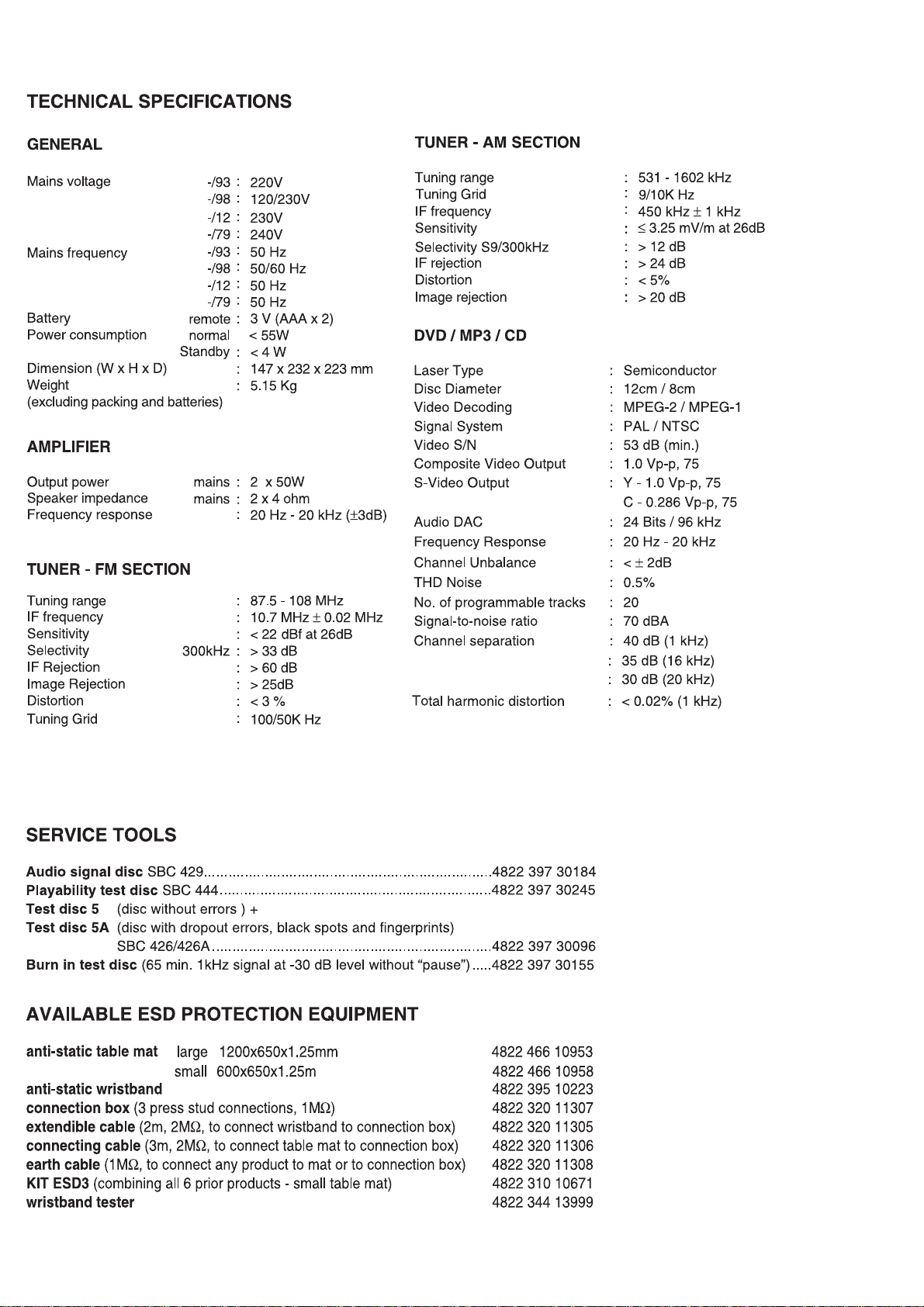
12 - 1
EXPLODED VIEW DIAGRAM
SCREW LIST :
1
M2.5x5
2
M2.5x8
3
M2.5x10
4
M3x8
5
M3x10
6
TP2.5 x 4
7
TP2.5 x 10
8
T3 x 4
9
T3 x 8
0
T3 x 10
424
423
422
313
312
403
402
8(2x)
406
404
414
2(8x)
407
412
411
417
408
413
421
416
409
419
3(2x)
0(4x)
427
418
426
1(4x)
5(4x)
0(4x)
7(4x)
2(9x)
311
8(5x) 8(4x)
9(1x)
5(5x)
309
308
1(4x)
314
2(9x)
2(6x)
8(2x)
2(6x)
2(6x)
303
307
306
304
302
5(6x)
9(2x)
401
4(4x)
8(2x)
8(5x)
428
429
6(8x)
301
4(4x)
8(2x)
316
5(11x)
317
6(8x)
Page 32

12 - 212 - 2
MECHANICAL PARTSLIST - AMP PART
MECHANICAL PARTSLIST - DVD PART
ACCESSORIES
9940 000 03504 SPEAKER BOX ASS'Y
9940 000 03497 REMOTE HANDSET
9940 000 03506 SPEAKER CONNECTION WIRE (not for-/79)
9940 000 03584 SPEAKER CONNECTION WIRE (only for-/79)
9940 000 03507 AV CABLE (not for -/79)
9940 000 03585 AV CABLE (only for -/79)
9940 000 03508 AC LINE CORD ( -/98)
9940 000 03514 AC LINE CORD ( -/12)
9940 000 03456 AC LINE CORD (-/93/79)
9940 000 02562 AM ANTENNA HOLDER
9940 000 03516 1P WIRE 26# 1.5M
9940 000 03517 SINGLE JUMPER WIRE 26#
9940 000 03409 PHILIPS BRACKET ASS'Y
MECHANICAL PARTSLIST
301 9940 000 03478 AMP LENS
302 9940 000 03487 AMP VOLUME KNOB
303 9940 000 03465 AMP FRONT CABINET
304 9940 000 03481 LOGO LIGHT GUIDE
306 9940 000 03482 AMP SOURCE BUTTON
307 9940 000 03492 AMP SOURCE BUTTON-BRACKET
308 9940 000 03583 POWER TRANSFORMER 240V/50Hz ( -/79)
308 9940 000 03503 POWER TRANSFORMER 230V/50HZ ( -/93)
308 9940 000 03513 POWER TRANSFORMER 230V/50HZ ( -/12)
308 9940 000 03515 POWER TRANSFORMER 120/230V ( -/98)
401 9940 000 03479 DVD LENS
402 9940 000 03495 DVD DOOR BRACKET
403 9940 000 03466 DVD FRONT CABINET
404 9940 000 03488 DVD STANDBY BUTTON
406 9940 000 03496 DVD STANDBY BUTTON-BRACKET
407 9940 000 03484 DVD CONTROL BUTTON-1
408 9940 000 03485 DVD CONTROL BUTTON-2
409 9940 000 03493 DVD CONTROL BUTTON BRACKET
411 9940 000 03483 DVD SKIP BUTTON
412 9940 000 03494 DVD SKIP BUTTON BRACKET
413 9940 000 03486 DVD CONTROL BUTTON CENTRE
414 9940 000 03413 VFD DISPLAY
416 9940 000 03459 MOTOR RF-360C-13450
417 9940 000 03476 DVD DOOR
418 9940 000 03455 DVD MECHANISM RUBBER CUSHION(not for -/12)
418 9940 000 03185 DVD MECH. RUBBER CUSHION ( -/12)
419 9940 000 03461 DVD MECHANIS MKENWOOD 510
421 9940 000 03467 TOP COVER1
422 9940 000 03477 TOP LIGHT LENS
423 9940 000 03468 TOP COVER2
424 9940 000 03471 DVD TOP COVER
426 9940 000 03473 DVD BERA CABINET
427 9940 000 03505 DVD MPEG DECODER CARD ASS'Y
428 9940 000 03489 RUBBER FOOT(A)
429 9940 000 03475 DVD BOTTOM
9940 000 03457 AC SOCKET 1A/250V
9940 000 03499 FLAT FLEX CABLE 24P
309 9940 000 03467 TOP COVER1
312 9940 000 03468 TOP COVER2
313 9940 000 03469 AMP TOP COVER
314 9940 000 03472 AMP BEAR CABINET
316 9940 000 03491 RUBBER FOOT(B)
317 9940 000 03474 AMP BOTTOM
Note: Only these parts mentioned in the list are
normal service parts.
Note: Only these parts mentioned in the list are
normal service parts.
Page 33

13 - 1
ELETRICAL PARTSLIST - AMP PART
- DIODES -
DZ901 9940 000 02516 ZENER DIODE 5V1
ZD304 9940 000 03417 ZENER DIODE 5.6V
ZD301 9940 000 03417 ZENER DIODE 5.6V
DB1 9940 000 03418 THYRISTOR RS1010G(10A)
DZ303 9940 000 03419 ZENER DIODE BZX-79-B22V
DZ302 9940 000 03419 ZENER DIODE BZX-79-B22V
DZ302 9940 000 03501 ZENER DIODE BZX-79-B24V
DZ303 9940 000 03501 ZENER DIODE BZX-79-B24V
DB1 9940 000 03502 THYRISTOR RS808
LED1001 9940 000 03436 WHITE LED DIODE
LED1100 9940 000 03437 LED 3B4SCB01
LED1101 9940 000 03437 LED 3B4SCB01
LED1103 9940 000 03437 LED 3B4SCB01
LED1104 9940 000 03437 LED 3B4SCB01
LED1200 9940 000 03437 LED 3B4SCB01
LED1201 9940 000 03437 LED 3B4SCB01
- TRANSISTORS -
Q302 9940 000 02517 TRANSISTOR 2SB772
Q1 9940 000 03156 CHIP TRANSISTOR 9014
Q2 9940 000 03156 CHIP TRANSISTOR 9014
Q2 9940 000 02545 TRRANSISTOR 9014C
Q3 9940 000 02518 TRANSISTOR 8050C
Q3 9940 000 03438 TRANSISTOR BC547B
Q301 9940 000 03439 CHIP RESISTOR BC817-25
Q304 9940 000 03439 CHIP RESISTOR BC817-25
Q308 9940 000 03439 CHIP RESISTOR BC817-25
Q309 9940 000 03439 CHIP RESISTOR BC817-25
Q1 9940 000 03441 TRRANSISTOR 9015C
Q303 9940 000 03442 CHIP TRANSISTOR BC857C
Q305 9940 000 03442 CHIP TRANSISTOR BC857C
Q311 9940 000 03442 CHIP TRANSISTOR BC857C
Q306 9940 000 03443 MOSFET BUK7535-55A
Q307 9940 000 03443 MOSFET BUK7535-55A
Q310 9940 000 03444 CHIP TRANSISTOR BC847C
Q312 9940 000 03444 CHIP TRANSISTOR BC847C
Q4 9940 000 03445 CHIP TRANSISTOR BC857C
- IC -
IC302 9940 000 02526 IC 7812
IC1 9940 000 03421 IC TEA5757H
IC301 9940 000 03422 IC TDA8920BTH
IC303 9940 000 03423 IC TDA8922BTH
IC304 9940 000 03423 IC TDA8922BTH
IC305 9940 000 03424 IC 74HCU04D
Page 34

13 - 2
ELETRICAL PARTSLIST - AMP PART
IC306 9940 000 03425 IC HEF4013T
IC4 9940 000 03426 IC PT2323
IC5 9940 000 03427 IC NE008
IC6 9940 000 03427 IC NE008
IC11 9940 000 03427 IC NE008
IC7 9940 000 03428 IC PT2322
IC8 9940 000 03429 IC 4558
- COILS & FILTERS -
XT301 9940 000 03453 CERAMIC FILTER CRB 700KHz
XT302 9940 000 03454 CERMIC FILTER FREQUENCY 600KHz
CF2 9940 000 03153 CERMIC FILTER FREQUENCY 10.7MHz
CF1 9940 000 03153 CERMIC FILTER FREQUENCY 10.7MHz
T1 9940 000 03446 I.F.T. COIL 44023
T2 9940 000 03447 I.F.T. COIL 20591
T3 9940 000 03447 I.F.T. COIL 20591
T4 9940 000 03448 I.F.T. COIL 20382
T5 9940 000 03449 I.F.T. COIL 44108
T7 9940 000 03451 I.F.T. COIL 43462
- MISCELLANEOUS -
X1 9940 000 03452 QUARTZ CRYSTAL 75KHz
JACK1 9940 000 02528 4PINS RCA SOCKET
ENCODER801 9940 000 02535 VOLUME CODER ED-1612-00-F15
S1 9940 000 02542 IR SENSOR
SPK1 9940 000 03431 5.1 SPEAKER JACK 6PZ-1
SW901 9940 000 03432 LIGHT TOUCH SWITCH
F301
F302
CN10 9940 000 03434 PIN CONNECTOR 40PINS
JACK1 9940 000 03435 ANT. LEADING-OUT JACK
9940 000 05328 ECO6-02 TUNER BOARD ASSY (only for -/12)
Note: Only these parts mentioned in the list are
9940 000 03433 FUSE F6.3AL250V
!
9940 000 03433 FUSE F6.3AL250V
!
normal service parts.
Page 35

13 - 3
ELETRICAL PARTSLIST - DVD PART
- DIODES -
BD201 9940 000 02521 THYRISTOR RS406
D210 9940 000 02544 RECTIFIER DIODE IN5822
DZ201 9940 000 03407 ZENER DIODE 3.3V
DZ202 9940 000 03408 ZENER DIODE 27V
LED601 9940 000 02537 LED LAMP 3R4CB71D-2B-208 -/12
- TRANSISTORS -
Q201 9940 000 02519 TRANSISTOR 8550C
Q202 9940 000 02519 TRANSISTOR 8550C
Q206 9940 000 02519 TRANSISTOR 8550C
Q208 9940 000 02519 TRANSISTOR 8550C
Q203 9940 000 02518 TRANSISTOR 8050C
Q204 9940 000 02518 TRANSISTOR 8050C
Q207 9940 000 02518 TRANSISTOR 8050C
Q209 9940 000 02518 TRANSISTOR 8050C
Q210 9940 000 02518 TRANSISTOR 8050C
Q205 9940 000 02545 TRRANSISTOR 9014C
Q2201 9940 000 02518 TRANSISTOR 8050C -/12
- IC -
IC202 9940 000 02547 IC AT24C02-PC27
IC203 9940 000 03162 CPU U252
IC205 9940 000 03411 IC D4558/RC4558
IC207 9940 000 02548 IC LM7805/LM340T5 7805
IC208 9940 000 02546 IC YD2576-ADJ
IC601 9940 000 02539 IC PT6311 / SC16311 / CD16311
IC201 9940 000 03512 CHIP IC AC6811-/12
- MISCELLANEOUS -
X201 9940 000 03152 CERMIC FILTER FREQUENCY 4.19MHZ
X202 9940 000 02551 CRYSTAL OSC FREQ.32.768 KHz
F201
F209
VFD701 9940 000 03413 VFD DISPLAY
RCA204 9940 000 03414 RCA SOCKET
SW601 9940 000 02543 LIGHT TOUCH SWITCH
SW602 9940 000 02543 LIGHT TOUCH SWITCH
SW603 9940 000 02543 LIGHT TOUCH SWITCH
9940 000 02529 FUSE F2AL250V
!
9940 000 03412 FUSE F1.5A/125V
!
SW605 9940 000 02543 LIGHT TOUCH SWITCH
SW606 9940 000 02543 LIGHT TOUCH SWITCH
SW607 9940 000 02543 LIGHT TOUCH SWITCH
SW608 9940 000 02543 LIGHT TOUCH SWITCH
JACK1301 9940 000 02556 OPTICAL & COAXIAL TERMINAL SOCKET
Page 36

13 - 4
ELETRICAL PARTSLIST - DVD PART
JACK202 9940 000 02553 3PINS RCA SOCKET(R/B/G)
CN210 9940 000 03415 PIN CONNECOTR 34PINS
JACK4 9940 000 03416 RCA SOCKET+S VIDEO
J1201 9940 000 02558 SINGLE RCA SOCKET
J104 9940 000 02527 4PINS SPEAKER SOCKET
9940 000 02566 110/220V AC CHANGE SWITCH -/98
REL1201 9940 000 03509 RELAY 10A 240VAC/30VDC -/12
J1501 9940 000 03511 SCART 21P SOCKET -/12
9940 000 04649
Note: Only these parts mentioned in the list are
normal service parts.
ECO POWER TRANSFORMER (-/12)
Page 37

14 - 1
REVISION LIST
Version 1.0 (3141 785 30730)
* Initial Release MCD708/93/12/98/79
Version 1.1 (3141 785 30731)
* Page 13-4 : Electrical partslist - Update
- Add ECO Power Transformer (only for -/12)
Version 1.2 (3141 785 30732)
* Page 9-1 : Circuit diagram - CPU Board
* Page 13-2 : Electrical partslist - Update
- Add ECO6-02 Tuner Board Assy (only for -/12)
- Update
 Loading...