

Page 1
MCD299/98
Service AIDS & CD playability ......................................1
Specifications ................................................................2
Connection & Controls ..................................................3
Disassembly Instructions ...............................................4
Block & Wiring diagrams ................................................5
TUNER BOARD ............................................................6
AMP BOARD .................................................................7
MAIN BOARD ................................................................8
DISPLAY BOARD ..........................................................9
KEY1 & KEY2 BOARD .................................................10
EXPLODE DIAGRAM ...................................................11
SERVICE PARTLIST ....................................................12
3141 785 31990
Page 2

SERVICE AIDS
1-1
Service Tools:
Universal Torx driver holder .................................4822 395 91019
Torx bit T10 150mm ...........................................4822 395 50456
Torx driver set T6-T20 .........................................4822 395 50145
Torx driver T10 extended .....................................4822 395 50423
GB
All ICs and many other semi-conductors are
susceptible to electrostatic discharges (ESD).
Careless handling during repair can reduce life
drastically.
When repairing, make sure that you are
connected with the same potential as the mass
of the set via a wrist wrap with resistance.
Keep components and tools also at this
potential.
WARNING
GB
Safety regulations require that the set be restored to its original
condition and that parts which are identical with those specified,
be used
Safety components are marked by the symbol
!
.
Compact Disc:
SBC426/426A Test disc 5 + 5A ...........................4822 397 30096
SBC442 Audio Burn-in test disc 1kHz .................4822 397 30155
SBC429 Audio Signals disc .................................4822 397 30184
Dolby Pro-logic Test Disc ....................................4822 395 10216
ESD
CLASS 1
LASER PRODUCT
Lead free
Page 3
1-2
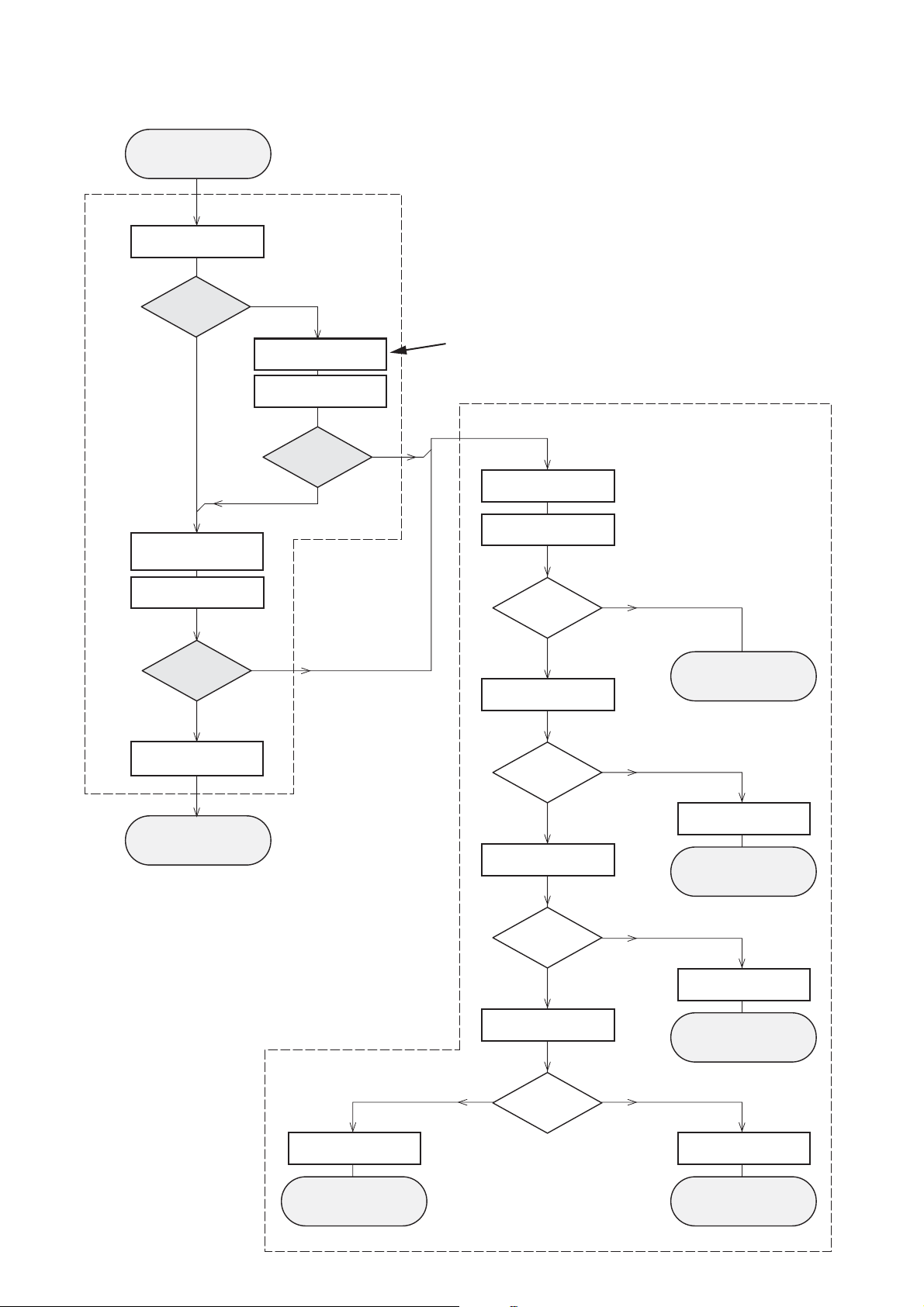
CD PLAYABILITY
Customer complaint
"CD related problem"
check playability
for at least 10 minutes
CHECK
playability
ok ?
Y
Play a CD
Set remains closed!
1
N
"fast" lens cleaning
check playability
playability
ok ?
Y
3
For flap loaders (= access to CD drive possible)
cleaning method
is recommended
4
Standard repair procedure
N
clean the lens
check playability
4
check playability
playability
ok ?
Y
add Info for customer
"SET OK"
return set
1
- 7
For description - see following pages
2
5
6
7
Y
return set
N
replace CD Drive
return set
N
replace CD Drive
return set
playability
ok ?
N
N
check "EYE-Pattern"
EYE-Pattern
ok ?
Y
check Laser current
Laser current
ok ?
Y
check CD Drive offsets
replace Signal Processor
return set
Y
CD Drive offsets
N
ok ?
replace CD Drive
return set
Page 4
1-3
CD PLAYABILITY
CHECK
1
PLAYABILITY CHECK
For sets which are compatible with
use CD-RW Printed Audio Disc....................7104 099 96611
TR 3 (Fingerprint)
TR 8 (600µ Black dot) maximum at 01:00
• playback of these two tracks without audible disturbance
playing time for: Fingerprint ≥
Black dot from 00:50 to 01:10
• jump forward/backward (search) within a reasonable time
For all other sets
use CD-DA SBC 444A..................................4822 397 30245
TR 14 (600µ Black dot) maximum at 01:15
TR 19 (Fingerprint)
TR 10 (1000µ wedge)
• playback of all these tracks without audible disturbance
playing time for: 1000µ wedge ≥10seconds
Fingerprint ≥10seconds
Black dot from 01:05 to 01:25
• jump forward/backward (search) within a reasonable time
CD-RW discs
10seconds
4
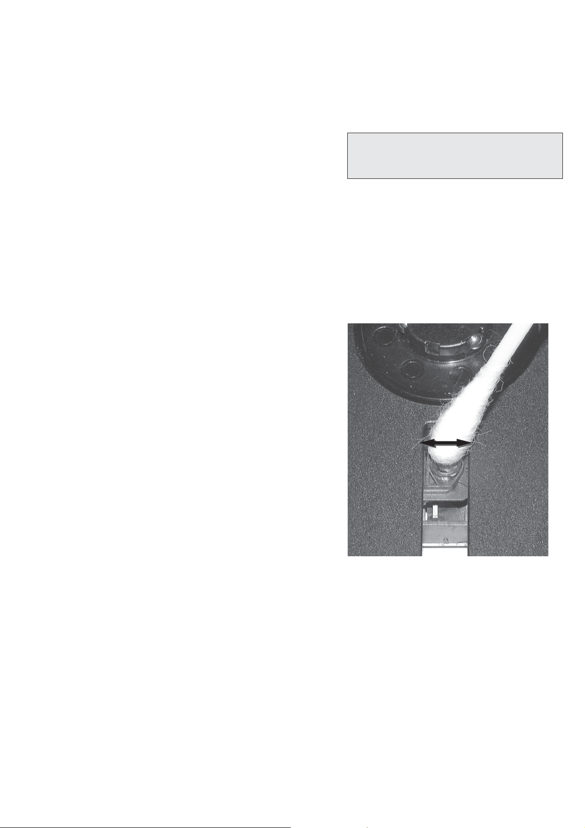
LIQUID LENS CLEANING
Before touching the lens it is advised to clean the
surface of the lens by blowing clean air over it.
This to avoid that little particles make scratches on
the lens.
Because the material of the lens is synthetic and coated
with a special anti-reflectivity layer, cleaning must be done
with a non-aggressive cleaning fluid. It is advised to use
“Cleaning Solvent B4-No2”, available with codenumber
4822 389 10026.
The actuator is a very precise mechanical component and
may not be damaged in order to guarantee its full function.
Clean the lens gently (don’t press too hard) with a soft and
clean cotton bud moistened with the special lens cleaner.
The direction of cleaning must be in the way as indicated in
the picture below.
2
CUSTOMER INFORMATION
It is proposed to add an addendum sheet to the set which
informs the customer that the set has been checked
carefully - but no fault was found.
The problem was obviously caused by a scratched, dirty or
copy-protected CD. In case problems remain, the customer
is requested to contact the workshop directly.
The lens cleaning (method 3) should be mentioned in the
addendum sheet.
The final wording in national language as well as the printing
is under responsibility of the Regional Service Organizations.
3
FAST LENS CLEANING (dry brush)
Use lens cleaning CD
SBC AC300...........................................9082 100 00043
Insert the lens cleaning CD, press PLAY and follow the
voice guide´s instructions on the CD.
Page 5

Sanyo DA12T3
CD Drive
A
A
F
C
B
E
C
D
E
VCC
B
VREF
F
D
9
10
11
12
13
14
15
16
1800
+5V_HF
VrefCD10
A
D
E
B
C
F
GND
8
E
D
A
B
C
F
Laser power control
100n
2878
470n
2876
3821
1R
1K
3823
2880
33p
+5V
BC807-40
7879
3817
47R
3820
4R7
47R
3819
1n
2879
2877
47u
1
8
4
7811-A
LM358D
3
2
10K
3822
47R
3818
2841
100n
47n
2869
+5V_HF
LASER DIODE
U >250mV
->Laser damaged !
4,6V
3V
3,3V
3,9V
2V
0,17V
0,17V
Sanyo
DA12T3
HF-Amplifier
D3
D2
D1
680R
3905
3903
3K3
BC847B
7877
47n
2818
1K5
3902
5
7
4
2
1
6
3
64
8
9
10
11
470R
3893
+3.3V
2K2
3908
10K
3923
BC847B
7878
BC847B
7876
4n7
2813
3896
100R
220u
2885
2881
560p
47n
2887
560R
3901
2883
470n
2817
4u7
3n3
2814
3898
220R
3895
27K
470n
2884
+3.3V
3909
820R
3907
100R
3920
33K
3897
2882
82p
3K3
3904
2K7
3899
3906
470R
+5V_HF
HFIN
VrefCD10
100p
28152816
22n
LDON
to 3826,3827
VREF GE
VDDA1
VRIN
VSSA1
ISLICE
LD
ON
D1
D2
D3
D4
HFIN
HFREF
IREF
CD_DA: 0V / CD_RW: 3V
Σ
(A-D)
800mVpp
TB = 0.5µs/div
EYE-PATTERN
1,8V
1,2V
2,4V
2,6V
0,65V
CD PLAYABILITY CHECK
1-4
5
EYE-PATTERN SIGNAL – JITTER MEASUREMENT
Measure the signal on the input of the Signal processor
using an analog oscilloscope. Please find the exact
measuring point in your Service Manual.
See below examples of the signal. Amplitude should read at
least 700mVpp using SBC444A.
6
CD DRIVE – LASER CURRENT MEASUREMENT
The laser current can be measured as a voltage drop on a
resistor. The resistor is marked in every Service Manual.
The value depends on the type of CD drive.
typical value most probably defect
VAMxxxx : 150-230mV
MCDxx : 170-230mV
DA1x : 210-250mV ≥350mV
DA2x : 175-200mV
Use SBC444A (CD-DA) for measurement.
≥
350mV
≥
300mV
250mV
≥
If the oscilloscope shows a signal like the ‘bad’ one, and/or
the amplitude decreases within 1 minute - the CD drive has
to be replaced.
good
bad
7
CD DRIVE – OFFSET MEASUREMENT
The photodiodes of the CD-drive may have an offset. These
offsets have to be compensated by the signal processor.
High offsets can lead to poor playability of some CDs
(skipping tracks).
To measure the offset values, start the
Program - section “Focus Test” without a CD.
The offsets can be measured with a DC Millivoltmeter
directly on the connector (see drawing below). Pin
numbering varies from drive to drive.
The values from diode A-D should read 0±10mV.
Diodes E and F are less critical.
If one of the offsets is higher than ±10mV the CD drive has
to be replaced. Otherwise replace the Signal Processor.
Service Test
Page 6

2 - 1
AMPLIFIER
Output power ............................................. 140 W RMS
Signal-to-noise ratio .......................................
≥
60 dBA
Frequency response ...... 150 – 20000 Hz, ± 3 dB
Input sensitivity AUX ....................... 0.5 V (max. 2 V)
Impedance loudspeakers ......................................... 6
Impedance headphones .................... 32
D
VD PLAYER
Ω
-1000
Ω
Ω
Laser Type ................................................ Semiconductor
Disc Diameter .............................................. 12cm / 8cm
Video Decoding ........................... MPEG-2 / MPEG-1
Video DAC ................................................................ 10 Bits
Signal System ............................................... PAL / NTSC
Video Format ..................................................... 4:3 / 16:9
Video S/N ........................................... 56 dB (minimum)
Composite Video Output ................ 1.0 Vp-p, 75 Ω
Audio DAC .......................................... 24 Bits / 96 kHz
Frequency Response .... 4 Hz - 20 kHz (44.1kHz)
...................................................... 4 Hz - 22 kHz (48kHz)
...................................................... 4 Hz - 44 kHz (96kHz)
Digital Output .........................................................................
....... SPDIF (Sony Philips digital interface) Coaxial
Number of programmable tracks ......................... 20
Signal-to-noise ratio ....................................... ≥ 60 dBA
40 dB (1 kHz)
Channel separation ..........................
≥
Total harmonic distortion...............< 0.1% (1 kHz)
TUNER
FM wave range ...................................87.5 – 108 MHz
Sensitivity at 75 Ω
– mono, 26 dB signal-to-noise ratio ............ 2.8 µV
– stereo, 46 dB signal-to-noise ratio ........ 61.4 µV
Tuning grid ............................................................ 9/10 kHz
15 dB
Selectivity .................................................................
≥
Total harmonic distortion ..................................... ≤ 5%
Frequency response ............ 40 – 5000 Hz (-6 dB)
Signal-to-noise-ratio ...................................... ≥ 58 dBA
SPEAKERS
Front Speakers
Impedance ........................................................................ 6 Ω
Sensitivity .............................................................. 80 ± 4dB
Frequency response ............................. 150Hz-20kHz
Dimensions .... 171 (W) x 297 (H) x 89 (D) mm
W
eight
.........................................................
1.265 kg/each
Subwoofer
Subwoofer (not magnetically shielded design).....
.................................................................................................... 8”
Impedance ........................................................................ 8 Ω
Output power ........................................................... 80 W
Dimensions (w x h x d) ....................................................
..................................... 220 mm x 350 mm x 357 mm
Weight ......................................................................... 9.66 kg
USB PLAYER
USB ................................................................... 12Mb/s, V1.1
......................................... support MP3 and WMA files
Number of albums/folders ................. maximum 99
Number of tracks/titles ...................... maximum 999
GENERAL INFORMATION
AC Power ........................... 110 – 127 / 220 – 240 V;
....................................................... 50/60 Hz Switchable
Dimensions (w x h x d) .. 450 x 335 x 115 (mm)
W
eight (with/without speakers) ....... 5.63 / 3.1 kg
Standby power consumption ............................ ≤ 4W
Specifications and external appearance are
subject to change without notice.
Page 7

CONNECTION AND CONTROLS
3 - 1
2
1
Step 2: Antennas Connection
antenna to the respective terminals. Adjust the
position of the antenna for optimal reception.
MW Antenna
Connect the supplied MW loop antenna and FM
VCR or other radiation source.
● Position the antenna as far as possible from a TV,
L
R
Ω
A/V OUT
Y/Pb/Pr OUT
SPEAKERS 6
CONNECT TO SUB WOOFER
AC CORD
Step 1: Connecting speakers
terminals: right speaker to
Place the main set with the front side facing
down on a flat and firm surface.
1
(left)
Speaker
"R" and left speaker to "L".
SPEAKERS (6 Ω)
2 Connect the two front speaker cables to the
Remove the detachable cover at the left bottom
of the main set to expose the CONNECT TO
SUB WOOFER terminal.4Connect the CONNECT TO SUB
WOOFER terminal of the main set to the
3
FM Antenna
CONNECT TO MAIN SET terminal of the
subwoofer with the supplied 15-pin D-Sub cable
by matching the pins. Fix the two screws on the
connectors to ensure firm connection.
click.
Notes:
– Ensure that the speaker cables are correctly
5 Mount the detachable cover back until hearing a
outdoor FM antenna to the FM ANTENNA
terminal.
● For better FM stereo reception, connect an
connected. Improper connections may damage the
system due to short-circuit.
–For optimal sound performance, use the
supplied speakers.
– Do not connect speakers with an impedance
lower than the speakers supplied. Please refer to
the SPECIFICATIONS section of this manual.
– The delivery-attached 15-pin D-Sub cable is
intended for use with this system only. Never try it
on any other devices (e.g., do not use it in
connection of your PC).
MW loop antenna
automatically under extreme conditions. If
(not available for all versions).
this happens, let the system cool down
before reusing it
Note:
– Before installation is finished, it is not
recommended to remove the protective plastic film
attached to the surface of the front panel to avoid
any scratch caused during installation.
TV IN
IN
VIDEO IN
S-VIDEO
IN
AUDIO
To avoid overheating of the system, a safety
circuit has been built in. Therefore, your
TV IN
IN
VIDEO IN
S-VIDEO
IN
AUDIO
FM wire antenna
L
R
Ω
A/V OUT
Y/Pb/Pr OUT
SPEAKERS 6
CONNECT TO SUB WOOFER
system may switch to Standby mode
A/V cord
AC CORD
Subwoofer
(right)
Speaker
–The voltage selector located at the
rear of this system is preset at
220V-240V from the factory. For
countries that operate at 110V-127V,
please adjust to 110V-127V before you
switch on the system.
– Before connecting the AC power cord
on the rear of the subwoofer to the wall
outlet, ensure that all other connections
have been made.
–Never make or change any
connections with the power switched on.
– High voltage! Do not open. You run the
risk of getting an electric shock.
– The machine does not contain any
user-serviceable parts.
– Modification of the product could
result in hazardous radiation of EMC or
IMPORTANT!
– The type plate is located at the rear of
AC power
cord
the system.
other unsafe operation.
Page 8

CONNECTION AND CONTROLS
3 - 2
cord
Step 5: Connecting the power
After everything is connected properly,
plug in the AC power cord on the rear of
the subwoofer to the power outlet.
power switched on.
Never make or change any connection with the
speakers
Step 4: Placing the set and
mounting kit, you can either place the main set
and speakers on desktop or mount them onto
wall. Desktop installation is taken for example
With the supplied detachable stands and wall
here. For how to mount the system onto wall,
Listening to the playback of a non-USB
Optional: Connecting additional
equipment
all
W
device
4 of the larger-
PRESS
please refer to Appendix and the attached
Mounting Instructions.
size stand with the slots at the bottom of the
main set.
1 Align the side marked
UDIO OUT
A
VCR
(for example)
L
R
Ω
A/V OUT
Y/Pb/Pr OUT
speakers in the same way.
4 Place the main set and speakers upright on the
SPEAKERS 6
CONNECT TO SUB WOOFER
desktop with the support of the stands.
Note:
–To remove the stand from the main set or either
R
L
a click.
2 Push the stand down into the slots until you hear
3 Attach the two smaller-size stands to the
speaker, while pressing down PRESS4, pull the
stand out from the slots.
X IN (R/L) jacks to
visual device (such as a VCR, Laser Disc player or
cassette desk) (cable not supplied).
the front panel to select AUX or press AUX on
the AUDIO OUT jacks on the other audio/
● Connect the system's AU
the remote control in order to activate the input
● Before starting operation, press SOURCE on
source.
Using Y Pb Pr OUT jack
IMPORTANT!
– The progressive scan video quality is
only possible when using Y Pb Pr, and a
progressive scan TV is required.
IMPORTANT!
–You only need to make one video
connection from the following options,
Step 3: Connecting TV
depending on the capabilities of your TV.
– Connect the DVD system directly to
R
the TV.
Using AV OUT jack
) jack to the
L
R
Ω
A/V OUT
Y/Pb/Pr OUT
SPEAKERS 6
CONNECT TO SUB WOOFER
Pr/Cr Pb/Cb Y
connect the COMPOENT VIDEO
OUTPUT (
corresponding Component video input jacks (or
labeled as Y Pb/Cb Pr/Cr or YUV) on the TV.2If you are using a Progressive Scan TV (TV must
indicate Progressive Scan or ProScan capability),
to activate TV Progressive Scan, please refer to
your TV user manual. For DVD system
Progressive Scan function, see "Preparations-
Setting up Progressive Scan feature".
Note:
– If your TV does not support Progressive Scan, you
will not be able to view the picture.
1 Use component video cables (red/blue/green) to
TV IN
IN
VIDEO IN
S-VIDEO
IN
AUDIO
TV IN
IN
VIDEO IN
S-VIDEO
IN
AUDIO
L
R
Ω
A/V OUT
Y/Pb/Pr OUT
SPEAKERS 6
CONNECT TO SUB WOOFER
only one connector to the AV OUT jack of the
DVD system.
1 Connect the end of the supplied AV cord with
connector (yellow) to the video input jack (or
labeled as A/ V In, CVBS, Composite or
Baseband) on the TV. To hear the sound of this
DVD system through your TV, connect the audio
connectors (white/ red) to the audio input jacks
on the TV.
2 For the other end, connect the video output
Page 9

CONNECTION AND CONTROLS
7
2
5
0
4
9
7
8
3 - 3
9
1
&
(
7
9
5
0
%
@
*
$
2
3
)
4
(
8
7
8
6
≤
#
!
¡
™
∞
§
^
£
≥
Controls
1
Connecting a USB device or memory
7
!
@
3
9
6
7
9
#
socket.
card
IMPORTANT!
– Before connecting the USB plug, first
slide open the protective cover on the
By connecting a USB mass storage device
(including USB flash memory, USB flash players
or memory cards) to the Hi-Fi system, you can
enjoy the device's stored music through the
powerful speakers of Hi-Fi system.
Insert the USB device's USB plug into the
●
R
L
UDIO IN
VIDEO IN
A
or the devices with USB cables:
socket on the set.
f
to the socket on the set.
1 Insert one plug of the USB cable (not supplied)
USB output terminal of the USB device.
2 Insert the other plug of the USB cable to the
for the memory card:
supplied).2Use a USB cable (not supplied) to connect the
card reader into the socket on the set.
1 Insert the memory card into a card reader (not
Using the VCR for recording DVDs
L
R
Ω
A/V OUT
Y/Pb/Pr OUT
SPEAKERS 6
VCR
CONNECT TO SUB WOOFER
the DVD system.
only one connector to the A/V OUT jack of
1 Connect the end of the supplied AV cord with
This will allow you to make analogue stereo
connector (yellow) to the VIDEO IN jack on the
(two channel, right and left) recordings.
VCR and the audio connectors (white/ red) to
the corresponding audio input jacks on the VCR.
2 For the other end, connect the video output
Page 10

CONNECTION AND CONTROLS
3 - 4
™ A-B
Controls
9 OK
within the same track.
–for VCD/CD/USB: to repeat a specific section
–for DVD: to repeat a specific section in a disc.
– selects different levels of brightness for the
£ DIM
track.
– Disc: skips to the previous/next chapter/title/
– to exit or confirm the selection.
0 í/ë
or VCD
display screen.
f
≤ AUDIO
! 9
–Tuner: selects a preset radio station.
–for clock/timer, to set the minute.
sets Stereo, Mono-Left or Mono-Right sound
mode.
–
program.
– In DISC/USB mode, to stop playback or clear a
or DVD
f
@ 2;
selects an audio language.
–
∞ ZOOM
playback.#VOL +/-
– In DISC/USB mode, to start or interrupt
picture or active image on the TV screen.
for this version)
–DVD/VCD/Picture CD: enlarges or reduces a
§ ANGLE/RDS (RDS function unavailable
$ MODE
– adjusts the volume upward/downward.
– selects various repeat modes or the shuffle play
entering a time, title, chapter or track.
*– DVD: selects a DVD camera angle.
–In DISC mode, to fast search in a disc by
≥ GOTO
mode for a disc.%SUBTITLE
– selects a subtitle language.
^ TIMER/SLEEP
Notes for remote control:
– First, select the source you wish to
control by pressing one of the source select
keys on the remote control (DISC or
TUNER, for example).
– Then select the desired function ( 2;, í,
Standby mode
automatically.
Power-on mode
– sets time for switching on the system
– sets the sleep timer function (auto off).
– selects a disc tray for playback.
& DISC 1/2/3/4
ë for example).
DSC/DBB
*– selects different types of preset sound equalizer
*
settings (FLAT, POP, CLASSIC, ROCK, JAZZ).
L ç/ R ç
– opens/closes the left/right disc door.
– enables or disables bass enhancement.
(
) MUTE
playback.
DISPLAY/OSD
– to interrupt or resume sound reproduction.
– displays information on TV screen during
¡
* = Press and hold the button for more than three seconds.
# USB DIRECT
Controls
Controls on the system
y
4 RIGHT ç
inputs a track/title/chapter number of the disc.
–
– opens/closes the right disc door.
VD/VCD/CD/MP3-CD/USB: enters the
3 PROGRAM
–D
5 iR SENSOR
– remote sensor
STANDBY-ON
Controls on the remote control
– jack for the external USB mass storage device.
STANDBY-ON y
1
1
– switches the system on or to standby mode.
2 Numeric Keypad (0-9)
– switches the system on or to standby mode.
– shows the status of the system.
3 LEFT ç
– opens/closes the left disc door.
2 Display screen
uner: programs preset radio stations.
program menu.–Picture CD: during playback, to select a slide
show mode.
+
/
-
6 VOLUME
– adjusts the volume level.
to select the respective sound source: DISC,
–T
4 SOURCE
–
7 Disc trays
8 Mode Selection
USB, TUNER (FM/MW) or AUX.
à / á
for TUNER .................... tunes to a station.
(disc mode only)
menu.
–DVD/VCD: enters or exits the disc contents
5 SYSTEM MENU (disc mode only)
6 DISC MENU
– to enter or exit the system menu bar.
forward within a track/disc.
*for DISC/USB ........... fast searches back and
for Clock/Timer ......... sets the hour.
– VCD2.0: switches the playback control mode on
erases a disc program.
ÉÅ ............................... starts or interrupts
9 ......................................... stops disc playback or
or off .7à / á
playback.
¡ / ™
Tuner
gradually.
automatic search for a radio frequency
– press to tune to a lower/higher radio frequency
– press and hold, then release the key to start
station.
chapter/title/track.
for TUNER .................... selects a preset radio
for DISC/USB .............. skips to the previous/next
for Clock/Timer ......... sets the minute.
DISC 1/2/3/4
9
Disc/USB
downward/upward.
– selects a disc tray for playback.
the disc menu or system menu bar.
– searches fast backward/forward.
– In DISC mode, to select a movement direction in
0 CLOCK
Standby mode
*– sets the system clock.
the disc menu or system menu bar.
8 3/4
–for clock/timer, to set the hour.
– In DISC mode, to select a movement direction in
– selects different slow playback modes for a VCD/
SOURCE
USB, TUNER (FM/MW) or AUX.
Playback mode
– displays the system clock.
– to select the respective sound source : DISC,
!
SVCD/DVD.
DSC•DBB
settings (FLAT, POP, CLASSIC, ROCK, JAZZ).
@
*– selects different types of preset sound equalizer
– enables or disables bass enhancement.
* = Press and hold the button for more than three seconds.
Page 11
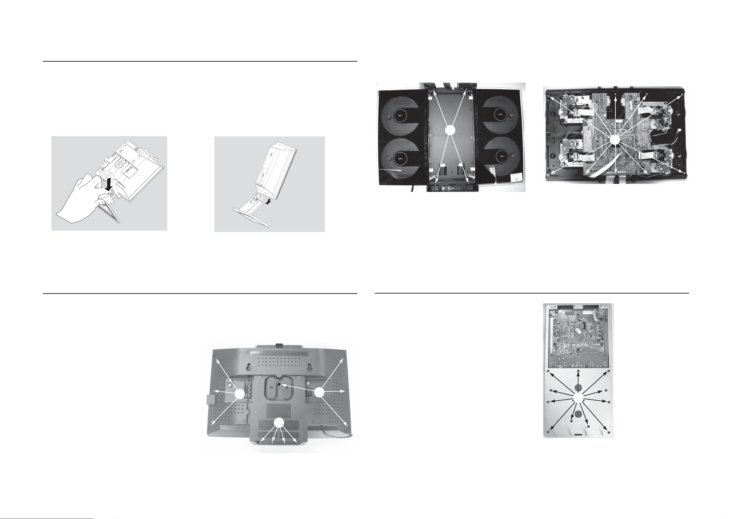
DISMANTLING INSTRUCTIONS
Detaching the Stands from the Speakers and Main Sets
1
To
detach the stand from the main unit,
4-1
Detach the speaker stands in the same way as
2
4-1
a. As shown, hold down
b.
Move out the stand to detach.
PRESS
1
4
you do the main unit stand#
C
D
Figure 2
Figure 3
Dismantling of the Front and Rear Panel assembly
1) Loosen 4 screws A to remove the Front Panel Ass’y by sliding it
out towards the underside before lifting up as shown in Figure 1.
2) Loosen 7 screws B and 4 screws C to remove the Rear Panel
Ass’y .
- 7 screws on the rear
- 2 screws each on the upside & downside
as shown in Figure 2.
3) Loosen 10 screws D(see Figure 3) to remove the CD Door
Track, then remove Left and Right CD Door.
- 5 screws each on the upper & under side.
B
A
Figure 1
B
Detaching the Control Panel Ass’
1) Loosen 11 screws E (see Figure 4) to remove the Control
Panel Ass’y .
y from the Front Panel Ass’y
Figure 4
E
Page 12
DISMANTLING INSTRUCTIONS
4-2
4-2
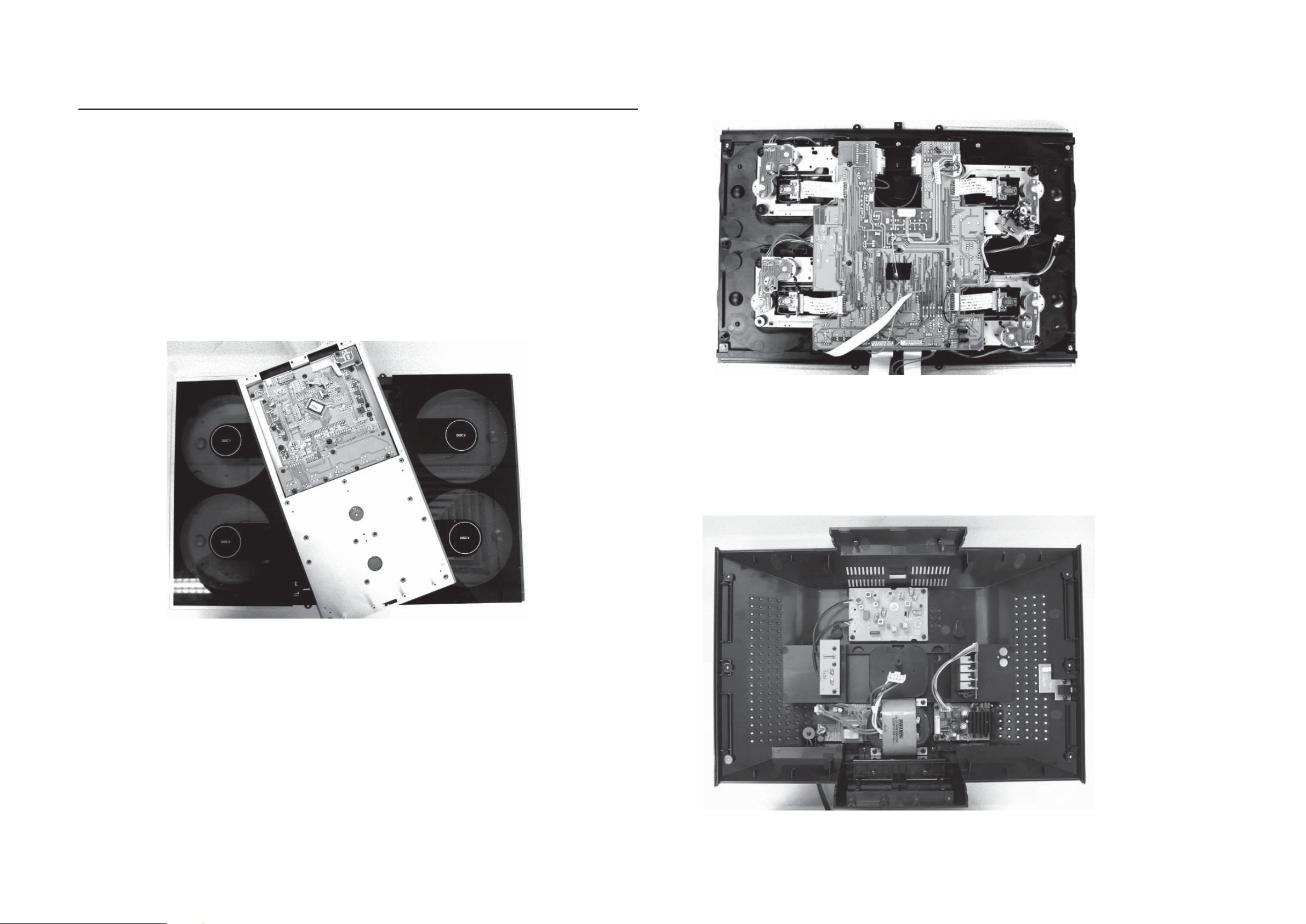
Repair Hints & Service Positions
1) During repairit ispossibleto disconnecttheTuner Board
and/or CD Module completely unless the fault is suspected to be in that area. This will not affect the
performance of the rest of the set.
Service position A
Service position B
Note: Theflexcablesarevery fragile,care shouldbe taken
not to damage them during repair. After repair, be
very sure that the flex cables are inserted properly
intotheflexsocketsbefore encasing,otherwisefaults
may occurs.
Service position C
Page 13

SET BLOCK DIAGRAM
A
C
I
N
P
U
T
120
5 - 1
USB JACK
+
12
V
-12
POWER
TRAN
SF
O
R
M
E
R
V
/
230
V
GND
13
EC
-20V
GND
20
+
M
C
V
V
O
P
O
W
E
R
R
E
S
E
T
V
U
5
.
6
V
H
S
A
L
F
M
8
24C0
5 - 1
2
COAXIAL
Y.V.U OUT
SUB 100W L 50W
Open Door
FM IN
AM IN
R 50W
TEA5762H
RADIO PACK
HEADPHONE
TDA7291x2
TUNER
LIN OUT
CONTRO
L
RC4558
C
I
IC RC4558D
D
L
TUNER OUT
R
AUX-IN
SDRAM
4MX16
27
M
H
Z
S
RD
SAA6581
MT1389HD
T
GY365
32.768M
H
Z
S-VIDEO
VIDEO
10MHZ
HT1622
LCD 28PIN
24C01
Keystoke
IC TDA8920
IC TDA8920
SUB PCB
RC4558D
IC
RC4558D
IC
OSC
IC RC4558D
IC TDA7468
(DRIVER)
BA5954
(DRIVER)
BA5954
DVD LOADER 1 DVD LOADER 2
1
1
4052x
IC
(DRIVER)
BA5954
(DRIVER)
BA5954
DVD LOADER 3 DVD LOADER 4
IR
Page 14

WIRING DIAGRAM
5 - 2 5 - 2
Page 15

CIRCUIT DIAGRAM - TUNER BOARD
6 - 1
6 - 1
A
FM 75 OHM
B
C
D
E
AM FRAME AERIAL
F
G
H
I
1
TUNER BOARD ECO6
1101
YKD21
A
YKD31-0432
1102
2
P01
2102
1131
T103
USA
2105
3
100n
2
1
1
100n
C-PAD
3108
2K2
LW =HIGH
T102
0.7V
USA
0V
2
1130
0V
LW only
0V
3
/ SYSTEMS-CENELEC
C-PAD
1110
FM FRONTEND
1
ANT
VCC
GND
4
3
5
6
2
7.2V
1.6-8V
T107
p
100n
2190
7104
BC337-40
varicap
V
2191
MIXER
9 10
100u
MW/LW-RF
MW
1103
XH-S
T105
2
T106
4101
1
5102
7
8
6
*
5
1
2
34
7KL
*
4102
B
LW
5103
4
6
P01
1 2 3 4
3
2
10p
2109
1
78
4K7
P0
3123
3125
8V
6.7V
10K
LW=HIGH
marked components not for LW version
2108
VDDVDD
3180
100p
8.3V
7.5V
BC857B
7109
0V
7.4V
10K
3128
2K2
IF-OUT
OSC-OUT
3195
100R
2106
7122
BC847C
0V
0.7V
FE450
7
8
3194
2K2
+FM
6105-1
1
HN1V02H
11p
LW only
BC337-40
0V
0.1V
6106
20p_LW
7105
0.7V
0.1V
3109
MW=HIGH
0V
0V
P0
4
2180
BAS216
2
7
4K7
3193
10n
2107
330R
3105
220R
T110
1u
AM-OSCILLATOR
47R
3132
*
4104
5
3190
120R
3192
330R
6
T104
D
C
T109
33p
2159
3142
T111
VCO
100K
1
p
2118
2125
*
2124
2p2
560p
10n
3134
5
22K
BC847C
6105
1
2
3
4
HN1V02H
5123
6
5122
6
8
7
6
5
6
3
6105-2
5
MW
34
HN1V02H
2
2120
1
22p
7
8
LW
78
22p_LW
p
10p
2119
34
2
2123
390p
1
3n3
2122
5 6 7
T112
7124
3141
56K
3191
120R
0V
5115
4
2
3
RDS only
3176
33K
0.7V
0.1V
7
7101
TEA5762
2165
100n
2V
2129
1
RIPPLE
100u
AM-RF
2
0V
3
FM-GND
4
RF-GND1
5
FM-OSC
0.1V
0V
6
AM-OSC
VCC1
7
7.8V
VCC1
8.2V
I-TUNE
8
1.6-8V
1-8V
VCO
9
1V
1.3V
10
AF-OUT
0.7V
3135
11
MPX-IN
1.2V
1K
220n
2127
6
8
7
1
BIRDY FILTER
VCC1
22K
3143
3144
1.3V
0.7V
2149
3137
22K
1K
BC857C
7103
MPX
33p
BUFFER
P0
MW=HIGH
LEGEND
* ... only assembled in FM/AM-version
p ...for provision only
USA ... for USA version only
LW ... for LW version only
8
9
10
11
12
13
VERSION PROGRAMMING COMPONENTS
2128
10u
AM DET
2131
0.2V
44
AGC
AGC
CTRL
RIPPLE
CHARGE
PUMP
LPF
12
0.8V
0.15V
2K2
3145
2133
470n
2132
470n
2169
to 1120
2n2
pin 5
AMPLIFIER
NC
MUTE
MPX
43
SCALER
VSTABA
VCC2
13
0.8V
RF-GND2
AM-IF
AM
FRONTEND
PRE-
STABILIZER
STEREO
DECODER
LEFT
0.6V
1u
3130
2134
AM-IF1
5111
4
6
8
T115
1.4V
42
41
AM-IF1-IN
MIXER
AM
OSC
MULTI-
PLEXER
VSTABB
VDD
RIGHT
15
14
0.6V
2138
5119
4
6
DISCRIMINATOR
3131
820R
820R
22n_USA
22n_USA
2135
15n
15n
450kHz
7
1.4V
40
AM-MIXOUT
AM
AGC
AGC
PILOT
16
1V
AM_FM
FILTER
1.2V
2u2
78
3
2
1
0.4V
AM|FM
IF-GND
T113
39
17
FM-IF1
5109
1
I3O
G
9V
1.4V
VSTABA
AM
IF
AM
DET
FM
DET
FM-DEMOD
1V
5118
2139
3
2
1
2150
100n
T114
FM-IF2
5110
3
I1O
1.4V
36
AM-IF2
AFC+
20
1.1V
2
1.1V
1.4V
0.7V
35
FM-IF2
VSTABB
CONTROL
XTAL
OSC
VCC2
FIELDSTR-IND
21
2V
11V
T116
VCC2
2141
100n
G
34
STEREO
VDD
22
FM-IF2-IN
AM-AFC
WRITE-EN
CLOCK
DIG-GND
MONO/
DATA
P1
P0
VCC1
VCC2
VDD
+FM
1.2V
0.7V
33
32
1.4V
31
7.5V
7.5V
30
0.1V
29
0V
28
27
26
1.4V
25
stereo 0.2V
24
mono 4.8V
23
VDD
7.8V
8.2V
8.2V
11V
8.2V
8.3V
7.5V
8.9V
0V
0V
8.2V
8.3V
7.5V
T118
2
0.7V
38
37
FM-IF1-IN
FM
IF1
FM
IF2
AGC
CONTROL
AGC
AFC
AFC-
18
19
0V
1.1V
T141
T142
470n
2164
0u10
2
15p
82p
2140
DT-381
T140
2130
100n
3169
150K
5121
2144
p
2161
75
3168
120R
22n
1u
AM-IF2
450kHz
5112
3 4
2
1
7
7P
AM-AFC
450kHz
5114
3 4
2
1
7
7P
LW
100n
2163
2166
1n
2167
12p
kHz
2145
220p
3167
120R
BC547C
3155
150R
AM_FM
8
8
P1
P0
12V
7112
7110
3150
6
6
BC857B
8.2V
10K
7101/39from
VERSION
/00 /02 FM/MW/LW
/00 /02 FM/MW
/01 FM/MW
/14 FM-OIRT/MW
/17 FM/AM
VERSION DETECTION
P1
PROGR.
OUTPUT PORTS
3170
100K
2n2
2147
2148
220p
from
2169
5K6
3172
9.6V
47K
3171
8.9V
68K
22u
3151
2162
3156
3157
2146
2143
3160
470R
BAS216
100K
0V
100K
3158
470R
MPX
T117
220p
220n
6120
component mounted
6120
0.2V
7111
BC847C
3161
22K
3159
470R
12Vtyp
(10-14V)
3154
330R
6107
BZX284-C11
22R
3146
3156
5V
0V
stereo
T123
T122
0V
T121
0V
T120
0V
ENABLE/MPX
T127
T126
1132
3153
470R
2137
220n
8 9 10 12 13 14
...V FM mode stereo
EVM
V
...V MW mode
...V LW mode
voltages measured while
set is tuned to a strong
transmitter
PBAS TUNER ECO6 AS
/02 3B RDS
3157
152 kHz, 50mVpp
mono
3
STEREO
CLOCK
DATA
VCC
RIGHT
T125
GND
LEFT
C-PAD
T124
3152
470R
220n
2136
14
3170
stereo
stereo 0.4V
mono 4.8V
8
7
6
5
4
3
2
1
FE-BT-VK-N
7111
1120
to/from
4
3103 308 64241
1101 A2
1102 B1
1103 E2
1110 B2
1120 E14
1130 A2
1131 C1
1132 F13
2102 B2
2105 A2
2106 E3
2107 E4
A
2108 G3
2109 G3
2118 H6
2119 H6
2120 G6
2122 I6
2123 H6
2124 H6
2125 H6
2127 E7
2128 B8
2129 C7
B
2130 F11
2131 F8
2132 F8
2133 F8
2134 I8
2135 I9
2136 H14
2137 H13
2138 F9
2139 G9
2140 G9
2141 F10
C
2143 G12
2144 G11
2145 E11
2146 E12
2147 E12
2148 E12
2149 H7
2150 A10
2159 D5
2161 C11
2162 H12
D
2163 D11
2164 F10
2165 C7
2166 D12
2167 E12
2169 G8
2180 C4
2190 C3
2191 C3
3105 D5
3108 D2
3109 G4
E
3123 H3
3125 H2
3128 H3
3130 I8
3131 I9
3132 G4
3134 H6
3135 E7
3137 H7
3141 E7
3142 E6
3143 G7
F
3144 G8
3145 F8
3146 G13
3150 H12
3151 H12
3152 G14
3153 G13
3154 F13
3155 G11
3156 C12
3157 C12
G
3158 E13
3159 D13
3160 D13
3161 D13
3167 F12
3168 F11
3169 D11
3170 C12
3171 G12
3172 G12
3176 G7
3180 I3
H
3190 B6
3191 B7
3192 B6
3193 B4
3194 C4
3195 C4
4101 E2
4102 F3
4104 H5
5102 E3
5103 F2
5109 B9
I
5110 B10
5111 A9
5112 A11
5114 B11
5115 F7
5118 G9
5119 G9
5121 E11
5122 H5
5123 G5
6105-1 E4
6105-2 G6
6106 D4
6107 G13
6120 C13
7101 C8
7103 H8
7104 D2
7105 F4
7109 H3
7110 H12
7111 C13
7112 G12
7122 H4
7124 H7
T102 B2
T103 C2
T104 B6
T105 E2
T106 E2
T107 C3
T109 D5
T110 D5
T111 E5
T112 F7
T113 A9
T114 B11
T115 B9
T116 F10
T117 F13
T118 G11
T120 F13
T121 F13
T122 E13
T123 E13
T124 G14
T125 F14
T126 F13
T127 F13
T140 F11
T141 F10
T142 F10
Page 16

VARICAP ALIGNMENT
FM RF
FM IF
VCO
AM IF
AM RF
3)
108MHz
87.5MHz
(65.81MHz)
87.5MHz
(65.81MHz)
87.5MHz
(65.81MHz)
279kHz
153kHz
1602kHz
531kHz
5130
check
5122
check
5123
check
8V
±
0.2V
4.3V
±
0.5V
(1.2V ±0.5V)
8V
±
0.2V
1.1V ±0.4V
8V
±0.2V
1.1V ±0.4V
1494kHz
558kHz
560kHz 5102
1500kHz
5103
198kHz
1494kHz
558kHz
560kHz
1500kHz
198kHz
2106
5102
2106
3142 152kHz
±
1kHz
1)
98MHz
5112
MAX
FM
87.5 - 108MHz
(65.81 - 74, 87.5 - 108MHz)
LW
153 - 279kHz
MW
FM/MW/LW- version, 9kHz grid
531 - 1602kHz
1700kHz
530kHz
5123
check
8V
±
0.2V
1.1V
±
0.4V
1602kHz
531kHz
5123
check
6.9V
±
0.2V
1.1V
±
0.4V
108MHz
108MHz 2155
5131
MW
FM/AM-version, 10kHz grid
530 - 1700kHz
FM
MW
LW
98MHz, 1mV
continuous wave
450kHz
connect pin 6 of
IC 7101 (AM Osc.)
with 3.3k
Ω
to Vcc
Use Service Testprogram. By selecting the TUNER TEST test frequencies will be stored as preset frequencies automatically.
4
1
3
5
5
A
A
5119
FM
10.7MHz, 45mV
continuous wave
2D
mod=1kHz
∆
f=±
22.5kHz
1)
If sensitivity of frequency counter is too low adjust to max. channel separation
(input signal: stereo left 90% + 9%, adjust output on right channel to minimum)
Repeat
ECO6, Sys + PA with frame aerial, 070799
TUNER ADJUSTMENT TABLE
( ECO6
FM/MW- and FM/MW/LW - versions with AM-frame aerial )
∆f=±
10kHz
VRF = 0.5mV
C
see
remark
2)
220R
100nF
36
IC 7101
220R
100nF
40
IC 7101
2141
shortcircuit
to block AFC
21
IC 7101
max.
symmetric
f
o
AM AFC
MW
C
continuous wave
VRF = 2mV
5111
5114
2
0 ± 2 mV DC
0 ±
3 mV DC
MW
4)
FM/MW/LW- and FM/MW-version
( 9kHz grid)
531 - 1602kHz
B
∆f = ±30kHz
V
RF
as low as
possible
max.
symmetric
f
o
MW
FM/AM-version, 10kHz grid
530 - 1700kHz
3)
For AM RF adjustments the original frame antenna has to be used !
2)
RC network serves for damping the IF-filter while adjusting the other one.
4)
MW has to be aligned before LW.
Waverange Input frequency Input Tuned to Adjust Output Scope/Voltmeter
FM
87.5 - 108MHz
(65.81 - 74, 87.5 - 108MHz)
FM/MW-version, 9kHz grid
531 - 1602kHz
(as low as
possible)
ECO6 System non Cenelec stage .3, 120900
TUNER BOARD ECO6
Systems non Cenelec
/
componentside view
1101 A6
1102 B6
1103 D6
1120 A4
1130 B5
1131 D5
1132 A5
2106 C5
2107 B5
2128 C4
2129 B4
2133 D2
2138 C2
2144 B2
2155 C4
3142 D2
5102 D6
5109 A3
5110 B3
5111 B4
5112 A3
5114 A2
5119 C2
5121 B2
5123 D5
5130 D3
5131 D4
7112 C1
9101 A2
9103 B2
9104 B5
9105 B1
9106 B3
9107 D4
9108 C4
9109 D2
AM FRAME AERIAL
FM 75
Ω
B
A
TUNER BOARD ECO6
Systems - non Cenelec
/
copperside view
2101 B4
2102 B1
2103 D4
2104 B4
2105 C1
2112 B5
2119 D3
2120 D3
2124 D3
2125 D3
2126 D6
2127 C5
2130 D5
2131 C5
2132 D6
2134 D7
2135 D7
2136 A4
2137 A4
2139 C6
2140 C6
2141 C6
2143 C7
2145 A5
2146 B7
2147 A5
2148 B6
2149 D6
2150 B5
2152 C5
2153 C5
2154 C4
2159 C5
2161 A6
2163 B6
2164 C6
2165 C4
2166 B6
2167 B6
2169 A4
3101 D5
3102 C3
3103 C4
3104 B4
3105 C4
3113 B5
3119 B5
3132 D5
3134 D3
3141 C5
3143 D6
3144 B7
3145 C5
3146 C7
3152 A4
3153 A4
3154 C7
3155 C7
3156 A6
3157 A6
3158 A4
3159 A5
3160 A5
3161 A5
3167 B7
3168 C7
3169 B6
3170 A6
3172 C7
3176 D6
3181 D4
4103 B5
4106 C4
4107 C5
4108 C5
6103 B3
6105 C3
6106 C3
6107 C7
6120 A6
6130 D4
6131 C4
7101 C5
7102 D4
7103 D7
7111 A5
7119 B5
These assembly drawings show a summary of all possible versions.
For components used in a specific version see schematic diagram respectively partslist.
ECO6 Systems non CENELEC stage .3, 120900
41..
in schematic diagram)
(not all items shown
SMD jumper
EB
C
A
K
1
2
7
8
4
D
A
C
1
2
5
3
V
dd
Vcc2
Vcc1
6 - 2
6 - 2
Page 17

CIRCUIT DIAGRAM - AMP BOARD
2R301
6.8k
2C399
+
10UF/25V
SW IN
-12VA
2CN301
8
LGND
RGND
15
7
VOL ALC
14
L+
+12VA
6
13
AC 12.5V
5
MT
12
AC12.5V
4
CLASSD1
11
ECO
3
10
R+
2
9
MCU5.6V
1
DB15
U802D
8 9
IC_74HCT04
+12VA
+
2C301
104P
2R203
4.7K*
2R205
15K
+
2C131
104
2C134
470UF/25V
ECO
12 13
2R302
1k
VOL ALC
2R213
100K
2R103
1001/2W
2C133
470UF/25V
2C132
104
2R105
100 1/2W
2R303
2R30482k
SW IN
2
3
3904
20V+
2D201 1N4148
220K
2R211
33UF/25V
11.9-12.4
11.9-12.4
82k
2R391 24k
Lin
Rin
56k
U802F
IC_74HCT04
7-1
2R306 68k
2C302 150P
U301A
NJM4558
-
+
2Q610
2C204
2Z101
2Z102
2R309
2C305
+
1
B-
10UF/25V
-12V
4
2C308
104
2R632
5.6K
2FB104
100
2R210
10K
2R316
4.7k
2R321
15k
2R611
2.4K
+
2FB103
100
2C376
+
2C611
OPEN
2Z201
2Q203
5.0V-5.2V
2R212
100K
+
2C103
104
100UF/25V
+
2C104
2C110
100UF/25V
2R315 68k
2C30310P
U302B
NJM4558
6
5
2C312
823P
2R325
82k
682P 2C377
2R392 24k
+12V
2R310
2R311
2R312
56k
15k
15k
FP
T4AL/250V
3.15AL/250V
2F901
2F902
230V
120V
2R307
18k
2R610
20K
2D612
1N4148
2C612
100UF/50V
3904
+12V
2C109
104
-12V
-
+
8
2R801
FP
2R204 4.7K
B+
2C309
104
220
2Z801
5.6V
2C801
SW1
2D613
1N4148
102
2R308
47k
2R611
OPEN
2Q208
3906
2D203 1N4148
2C306
+
0.22UF/25V
7
+12V
2L801
2R804
1K
T1
2C314
474
+20V
GND
-20V
682P
10UH
2C804
100UF/16V
+
2D204
2R322
+
2R317
2.7k
2R802
10k
B+
10K
2C207
330UF/25V
2R217
1N4148
GND
2R324
15k
2R805
1K
47K
2R101
10K
2R102
10K
14
7
2R323
10k
2C315
2C316
474
104
2C208
+
Mt
2FB101
100
2FB111
2FB110
100
2FB102
100
2R319
4.7k
2
3
2C313
2R326
823P
82k
2C880
104
IC802G
IC_74HCT04
U802A
IC_74HCT04
C802
102
R806
47K
1
2
3
To AMP PCB CN903
AC IN
22k
2R327
2R216
560
47UF/50V
2Q205
3904
2Z202
5.6V
100
2R318 68k
2C304 10P
U302A
NJM4558
B-
+
4
2C310
104
R813
2R811
0PEN
21
IC_74HCT04
C803
102
To AMP PCB CN902
2CN903
AC20V IN
2R218
39K
2R807
U802C
2X802
600KHZ
3
2
1
700KHZ
47K
2R809
2R328
6
5
2C209
224
2C101
104
2C102
104
2C307
+
0.22UF/25V
1
-12V
2C805332R803
2X801
2C807
100
2R812
1M
47K
2C317
222P
IC301B
NJM4558
-
+
power mt
+
2R808
2R810
47K
120k
B+
8
2C311
104
+20V
2C411
47UF/63V
VDDP
VDDP
+
2C107
470UF/35V
2C108
+
470UF/35V
VSSP
2R320
2.7k
10K
6.8K
65
10K
T4AL/250V
T4AL/250V
2R290
0
2R289
560
VSSP
2F904
2F905
3904
2C806
2Q801
2Q802
3906
C808 100
7
+12V
2R329
10K
IC501MUTE
2C409
104
VSSP
100
20V+
+12VA
IC501MUTE
2C410
104
2R313
2k
U802B
IC_74HCT04
2CN902
AC IN
2C911
104
2C912
104
2R305
2D914
1N5402
2D915
1N5402
1K
2C318
100P
2R6
22K
+
2C513
47UF/63V
2R106
10
2R107
10 1/2W
2C322
43
+20V
2R219
2R220
VSSP
VDDP
2R332
5.6K
474
AC12V A
AC12V B
AC11V A
AC11V B
22UF/50V
1K
2R222
470
10K
2C509
104
2R314
2k
2R401
5.6K
2R402
5.6K
U802E
IC_74HCT04
2C1
1N4003
2D916
1N5402
2D917
1N5402
2D207
2C510
104
2C961
+
47UF/50V
2C960
+
47UF/50V
1011
T1AL/250V
2D2
2C319
100P
CLK
2F908
T1AL/250V
2D1
1N4003
2C915
104
2C916
104
1N4148
2Z203
7.5V
2R330
5.6K
2C320
VDDAVDDP
VSSA
2F909
7-1
2R682
R607270 1/2W
+
14
VDDP1
VDDP2
23
104
2SW601
1
2
FAN
2C505
104
17
20
2C506
VSSP
BOOT1
VSSP1
BOOT2
VSSP2
104
2Q601
2N3904
OUT1
OUT2
2C507
7.5K
2R701
4.7K
ZD701
OPEN
+11V
2R604
4.7K
2C602
100UF/25V
2R626
12K
VSSP
VDDP
2R504
2R503
5.6
5.6
U501
15
2C525
2C526
2C522
560
560
153
16
2L501
30uH
2L502
21
30uH
2C527
22
2C528
560
2C523
560
153
2R505
2R506
5.6
5.6
VSSPVDDP
2R605
470 1/2W
2C601
2FB601
104
2Q209
2SA3906
R221
2C210
+
100UF/25V
2C501
104
474
8
2C512
330
9
2C511
11
474
2R501
2
5.6K
5
4
2C502
104
2.2UH
2Q602
2C503
12
104
VSSA1
OSC
7
OSC
8550
2R606
2.2K
100UF/25V
VSSP
19
HW
TDA8922TH
2C603
VDDP
IC501MUTE
6
MODE
2C504
104
power mt
1K
2Q207
2N3904
VDDA
VSSA
10
IN+
VDDA1
IN-
SGND1
SGND2
IN2+
IN2-
VSSA2
1
3
VDD2
2C508
104
24
VSSD
2C515
18
STAB1
224
13
PROT
2C518
68
CLK
2C413
474
2C321
2C412
474
2R331
5.6K
474
2C901
104
2C902
104
2C414
2C415
330
2C402
2C401
104
330
104
11
VSSA VDDA
VDDA
8
9
2
5
4
VSSA VDDA
2D901
1N4001
2D902
1N4001
IN+
IN-
SGND1
SGND2
IN2+
IN2-
VSSA
2C403
104
10
VDDA1
VSSA2
1
12
3
2D903
1N4001
2D904
1N4001
VSSA1
VDD2
2C408
104
2C903
104
2C904
104
OSC
7
OSC
24
VSSP
VSSP
19
HW
TDA8920TH
VSSD
STAB1
18
2C417
224
VSSP
VDDP
IC502MUTE
6
MODE
PROT
13
2C420
68
VDDP
VDDP
2C404
104
14
23
VDDP1
VDDP2
2C406
104
2C405
VSSP
104
17
20
BOOT1
VSSP1
BOOT2
VSSP2
2C407
104
VSSP
OUT1
OUT2
VSSP
2R814
22
2C809
OSC
100
VSSP
VDDP
2R404
2R405
5.6
U502
2C424
2C425
5.6
15
2C428
2C427
560
560
153
16
30uH
2L402
21
2C430
2C429
153
22
560
560
2R406
2R407
5.6
5.6
VSSPVDDP
2CN701
CN2/20
2L401
30uH
3
1
2
+
M824
CLK
2C421
M824
2C422
M824
ZD681
5.6V
2.7K
2D604
1N4148
SW1
224
2C516
2R507
2C521
153
2C519
M824
22 1/2W
2C524
2C520
2R508
22 1/2W
2C517
224
6
5
4
U801A
SET
REST
DATA
Q
Q
1
2
2C418
224
2C423
2R408
153
22 1/2W
2C426
2R409
22 1/2W
2C419
224
+12VA
-12VA
AC12.5V
AC12.5V
+ 22-27V
- 22-27V
GND
2D8
24V
2R14
680
2R16
150
2R7
22K
2C2
22UF/50V
2C933
4700UF/35V
2C927
104
2Q1
BUK7535
2R10
2.7K
2R11
100K
2C934
2D512V
2R3
47K
2Q3
BC847C
4700UF35V
2Q2
BUK7535
12V
2D6
2D7
24V
2R13
680
2C3
2R9
22UF/50V
2D4
2R15
2D3
1N4003
150
2C4
1N4003
22UF/50V
2R8
22K
2R4
47K
104
2C928
2R2
10K
2R1
10K
22K
2Q4
BC857C
2Q5
BC857C
2R12
2R5
100K
47K
2R683
T 10K
2Q681
2R681
10K
2D601
1N4148
2R601
1K
2N3904
2R686
2.7K
2D602
1N4148
2R602
1K
L+
R+
2R603
2D603
1N4148
1K
2R684
2R685
8.2K
SW1
SW1
1
2
153
11
8
9
10
U801B
4013
CLK
7
Gnd
4013
SET
14
DATA
Vcc
RESET
Q
Q
12
13
2C889
104
B+
L+
R+
153
Page 18

LAYOUT DIAGRAM - AMP PCB
7 - 2 7 - 2
Page 19

CIRCUIT DIAGRAM
8 - 1
MAIN BOARD - INDEX PART
-
8 - 1
MT1389HD_KHM31
0_E5T2A
MT1389/HD (LQFP256) DVD for Sony KHM310 PUH
1 INDEX & POWER, RESET
2 RF, SERVO & MPEG - MT1389E
3 MEMORY - SDRAM, FLASH/EEPROM
4 VIDEO OUT
5 AUDIO DAC PCM1742 AND AUDIO OUT
6 HDMI MT1392
NAME
VCC
DV33
+5V
V
AVCC
V18
SD33
+12V
VCC_AUD
I
O
TYPE
Digital
Digital
Video
RF 5V
Digital
Digital
Audio +
Audio
CN1
1
2
3
CON3
+12V
DEVICE
SUPPLY
MT138
PICKUP HE
MT1389E
SDRAM
OP AM
Audio DAC
VCC
9E
R
ADE
.
P
L
1
FB
MO_VCC
AVCC
VCC_AUDIO
+5VV
D35
1 2
1N4001
CB2
0.1uF
D36
2
1
1N4001
1
+
CE3
220uF/16V
3
CB3
0.1uF
+
CE2
220uF/16V
1Q5
+E
-E
1Q1
1
2
+E
EOUT
3
-E
7
1
1
LM1
+
CE1
220uF/16V
2
EOUT
7
1
1
LM1
V
5
3.3
V
5
V
1.8
V
3.3V
12V
V
5
Rev
V1
V2
R1
5.1K
FB18
R2
10K
CB1
0.1uF
R3
0K
3
FB3
R4
OPEN
RFV33 DV33
CB4
+
CE4
220uF/16V
0.1uF
.
The original release
d
HDMI + Card Reader Integrated Des
[2]
DVDD18
J.P
0
L2
V18
92_DV33
[2]
L2
1
J.P
L2
J.P
History
Date
P#
ig
n
URST#
URST# [2,7]
RFV33
RFV33 [2]
DV33
V18
DV33
VCC
AVCC
VCC_AUDIO
+12V
+5VV
GND
92_DV33
DVDD18
For MT1
D1
R5
10K
1N4148
1 2
URST#
8
V1
DV3
3
C
VC
C
AVC
VCC_AUDI
V
+12
+5V
V
GND
92_DV33 [7]
DVDD1
8 [7]
392
O
[2]
[2,3,5]
[2,3,4,5,6,7]
[2,3,4,5,6,7]
[2,3,4,5,6,7]
[4,5,6]
[2,3,4,5,6,7]
[2,3,4,5,6,7]
Place near
AT566
CE5
+
9
10uF
Page 20

8 - 2
CIRCUIT DIAGRAM - MAIN BOARD - RF & MPEG PART
8 - 2
V18
HA1
HEADER 24 SMD0.5 TOP
KHM310
IO_18
TCK
T
TOP
C45
0.1uF
RFV18
24
23
22
21
20
19
18
17
16
15
14
13
12
11
10
9
8
7
6
5
4
3
2
1
AVCC
USB
C40
0.1uF
STBY
MDI1
V1P4
LIMIT
E
V20
F
B
A
RFO
IOA
D
C
FMSO
TRSO
FOSO
DMSO
J5
C
1
R
6
RFVDD3
10uH
4
CB8
0.1uF
CB10
0.1uF
ADACVDD
1uF
E
F
LDO2
LDO1
RFVDD3
C41
0.1uF
R/NC
V18
6.8
PLLVDD3
C2
CE6
+
100uF/6.3v
0.1uF
C10
C9
2200pF
0.01uF
V1P4
CE13
C27
+
47uF
0.1uF
1uF
7
C3
C3
9
OPEN
10
11
12
13
14
15
16
17
18
DV33
19
20
21
22
23
24
25
26
27
28
29
30
31
32
33
34
35
36
37
38
39
40
41
42
43
44
45
46
47
48
49
50
51
52
53
54
55
56
57
58
59
60
61
62
63
64
MDI1
MDI2
USBVDD
ADIN
V18
R3
6
A2
A3
A4
A5
A6
A7
A8
A18
A19
V2P8
V20
V1P4
OPO
OPOP+
DMO
FMO
TROPEN
TRO
FOO
USBP
USBM
TDI
T
M
S
TCK
TDO
CB11
0.1uF
0
C28
0.1uF
1
AGND
2
DVDA
3
DVDB
4
DVDC
5
DVDD
6
DVDRFIP
7
DVDRFIN
8
MA
9
MB
MC
MD
SA
SB
SC
SD
CDFON
CDFOP
TNI
TPI
MDI1
MDI2
LDO2
LDO1
SVDD3
CSO/RFOP
RFLVL/RFON
SGND
V2REFO
V20
VREFO
FEO
TEO
TEZISLV
OP_OUT
OP_INN
OP_INP
DMO
FMO
TROPENPWM
PWMOUT1/V_ADIN9
TRO
FOO
VPLLVSS
CAPPAD
VPLLVDD3
USB_VSS
USBP
USBM
USB_VDD3
FG/V_ADIN8
TDI/V_ADIN4
TMS/V_ADIN5
TCK/V_ADIN6
TDO/V_ADIN7
DVDD18
IOA2
IOA3
IOA4
IOA5
IOA6
IOA7
HIGHA0
IOA18
IOA19
VDD3
RF
6
5
2
3
D
D
AV
3
D
D
V
D
5
6
P4
F
V1
F
p
5 0.1u
C
20
F
u
7
1
.
C
k
uF
7 0.1
R15 15
F
C1
u
F
u
033
1
.
.
0
0
0
2
1
C
2
C
2
3
5
5
5
5
254
2
2
2
251
F
N
E
S
ND
GC
R
OSP
O
G
I
RF
F
R
7
5
#
A
A
R
H
H
6
W
IGHA6
IG
IG
O
H
H
H
A1
I
9
6
8
70
6
6
67
6
4
2
5
6
1
1
1
A
A13
A
A
A1
PWR#
FOSO
TRSO
FMSO
DMSO
0
2 100k
F
R1
p
2
1
C
1000
6
3
1
D
C
D
F
F
V
u
F
R
047
.
3
0.047u
0
D
F
u
D
1
V
.
F
0
R
9
C2
9
0
8
4
5
4
2
246
2
2
247
3
P
C
C
C
L
D
Z
A
D
P
F
D
P
P
T
V
R
R
R
F
F
HR
F
C
R
R
R
2
4
1
3
A
A
A
A
0
H
H
H
H
2
A
IG
IG
IG
IG
O
H
H
I
H
H
1
3
2
75
74
7
7
7
0
0
1
2
11
CE#
9
A
P
A
A
A
C65
330pF
45
S
S
V
DC
A
#
S
C
O
I
6
7
1
A
C66
330pF
D3
2
2
C
C23
PLLVD
3
2
1
0
4
4
4
2442
24
2
2
2
P
I
FOP
PF
L
LPFIN
LP
LPFON
ADCVDD3
#
1
0
D
D
DVSS
A
A
IOCE
IOA1
1
0
9
8
8
78907
77
#
D
1
R
P
AD0
AD2
AD
C67
0.1uF
RFV33
L
4
V2P8
CE11
C25
+
47uF
0.1uF
LIMIT
IOAIO_19
STBY
NIRTSM
R38
0
LDO2
Very
VCC
USBP
USBM
Important
to reduce
Noise
LDO1
L7
FB
4
3
2
FB
1
L8
R54
R53
15K
15K
USB
C
B
A
D
RFO
C
B
A
D
V1P4
DV33
V20
C26
0.1uF
3 1uF
C3
C35 1uF
C3
6
C3
8
OPEN
C43
C/NC
CB9
5600pF
R32 0
C3
1uF
R31
CE12
+
47uF
JITFO
7
R
C
N
/
F
C11
47u
.
+
0
10uF/16v
O
I
X
X
4
1
C
0
0
2
21 0
R
R
O
N
I
F
L
T
I
A
JITF
J
XT
7
9
8
3
3
3
33
2
234
236
2
235
2
2
I
3
P
S
N
O
L
L
D
F
S
F
A
X
T
T
D
V
I
I
E
V
J
J
XT
LL
L
C
XTALO
P
L
A
P
D
I
C8
10uF/10v
CE10
+
100uF/10v
C18
1uF
S
L
L
ADACVDD
A
A
CTR
8
1
V
89_
89_
89_
F
R
7
2
8
9
3
2
2
22
231
230
2
226
2
2
)
8
8
2
1
0
R
1
1
A
D
D
T
D
D
D
C
AT
ND
D
V
V
(
V
D
G
C
C
F/
F
F
A
A
L
R
R
D
D
A
S/S
L
A
A
A
MT1389HD
Pin Assignment v1.5
8
1
2
6
4
3
5
2
A
D
D
D
D
D
O
A
A
A
A
I
A
3
4
2
85
8
86
87
8
8
#
1
5
4
3
60
D
D
D
A
A
A
V
AD6
R45 20k
R46 18k
R48 15k
R49 10k
C68
0.015uF
V1P4
1
D
S
S
D
7
7
V
V
1
D
A
A
D
UWR#URD#DVDD3U
D
IOA0
ALE
9
8
3
2
91
8
8
9
94
9
95
V18
7
D
0
A17
A
A
DV33
FOO
TRO
FMO
DMO
JITFN
390pF
750k
CE9
100uF/6.3v
+
CB6
0.1uF
+
1
P
T
C19
+
10uF/10V
S
W
R
R
S
A
A
89_
89_
89_
2
1
3
24
2
2
2
2
2
2
2
225
)
1
1
3
M
S
A
A
C
T
A
AT
VS
AV
D
D
C
RF(SW
S
A
/
A
D
S/S
R
A
AL/SDATA2
A
R
A
5
3
2
_
_4
_
_
1
1
1
P
P
P
U
UP1
U
0
7
8
0
9
991
96
9
#
B
A
K
1
T
D
C
60
VS
H
VS
VS
I
R?
M
10K
OPEN for HD
H
C
IT
W
T
DD3
S
A
_
D
M
GB
A
ASPDIF
R
APLLV
9
7
5
6
8
1
1
1
1
1
220
2
2
2
2
2
3
F
A
P
S
I
S2
T
D
S
D
A
V
D
D
V
SP
LL
_
LL
PLLCA
AP
A
MC
AP
ADACVS
4
1
7
5
_
_
_
_
3
3
3_0
1
1_6
3
P
P
P
P
U
U
UP
U
UP
U
5
3
2
4
6
0
0
0
0
0
101
1
1
1
1
1
1
0
_
_
3
3
L
A
P
P
C
D
D
D
U
U
S
S
E
X
C
I
RX
T
N
N
N
E
E
P
P
O
O
6 OPE
5
4
1K for CARD
7
7
1
1
R17
R
R
CT
0
1
SELE
S
S
F
F
P_S_
B
T
S
A
DACVDD3
C6
0.1uF
V18
CB7
0.1uF
K
K
C
3
C
3
3
R
T
L
V
A
AB
ACLK
A
D
K
D
C
S
A
SPLRCK
SPB
3
4
1
0
9
8
2
7
1
1
1
1
0
0
1
0
2
2
2
2
2
2
2
2
8
4
3
K
K
1
LK
A
A
C
C
D
R
AT
AT
D
AC
L
AB
D
D
V
A
SPBCK
DVDD3
S
S
D
A
A
#
0
T
6
S
T0#
E
QM
R
R
C
I
P
IN
I
D
IO_19
RD7
7
8
0
0
1
1
#
T
S
UR
R37
1k
RD
9
1
2
3
4
0
0
1
1
1
1
1
1
1
1
1
1
1
0
9
0#
1
_
QM
R
O
INT
I
DQ7
I
D
DQ5
DQ6
1K for HDM
OPEN for CA
1
R17
R17
2 1K
R173 1K
K
2
A
L
T
T
C
A
A
D
D
M
S
P
P
A
ASDAT1
S
S
5
4
6
3
2
0
0
0
0
0
2
2
2
2
2
0
A
K
K
_
L
T
C
O
A
C
D
LR
M
P
GP
P
/
SP
S
S
2
A
T
DA
AS
3
D
4
3
D
V
RD
RD5
RD
D
5
7
8
6
9
1
1
1
1
1
1
1
1
1
1
DQ4
DQ2
DQ3
RxD
TxD
CE7
+
10uF
I
D
R
1K
4
_
O
I
P
GPIO_5
GPIO_3
G
1
0
9
0
0
9
2
2
1
3
1
_
_
O
O
I
P
PIO_4
GP
G
G
/
1
A
T
DA
AS
RD1RD2RD0
2
1
0
2
2
2
1
1
1
DQ15
DQ0
DQ1
DV33
8
R
APLLVDD3
FS0
FS1
P_S_SELECT
0
6
T
_
A
F
O
I
D
E
P
S
R
G
A
DACVDD3
8
7
6
9
9
9
1
1
1
6
5
_
DDC
DACV
KB/GPIO
RCL
RVREF/GPIO_
ASDATA0/GPO_2
VSYNC/V_ADIN1
HSYNC/V_ADIN2
4
5
1
1
12RD1
RD
RD
RD13
RD
3
4
5
2
2
2
1
1
1
4
1
DQ
J4
4
3
2
1
DV33
0
CB5
0.1uF
FSV
4
9
193
195
1
F
FS
E
R
V
YUV0/CIN
DACVSSC
YUV1/Y
DACVDDB
YUV2/C
DACVSSB
YUV3/CVBS
DACVDDA
YUV4/G
DACVSSA
YUV5/B
YUV6/R
C0/IO_0
C1/IO_1
DVDD18
C2/IO_2
C3/IO_3
C4/IO_4
DVDD3
C5/IO_5
C6/IO_6
C7/IO_7
YUVCLK/IO_8
Y0/IO_9
Y1/IO_10
Y2/IO_11
Y3/IO_12
Y4/IO_13
DVDD18
Y5/IO_14
Y6/IO_15
Y7/IO_16
DVDD3
DVDD3
DVDD18
DVDD3
1
0
1
RD
RD9
7
2
1
128
126
SERIAL
+
R22
560
YUV7
DVSS
IO_17
RA4
RA5
RA6
RA7
RA8
RA9
RA11
DVSS
CKE
RCLK
RA3
RA2
RA1
RA0
RA10
BA1
BA0
RCS#
RAS#
CAS#
RWE#
DQM1
IO_18
RD8
U1
MT1389DE/H
R9
0
CE8
100uF/6.3v
C.E.AI-2.5(D6MM)
C24
0.1uF
192
191
190
189
188
187
186
185
184
183
182
181
180
179
178
177
176
175
174
173
172
171
170
169
168
167
166
165
164
163
162
161
160
159
158
157
156
155
154
153
152
151
150
149
148
147
146
145
144
143
142
141
140
139
138
137
136
135
134
133
132
131
130
129
DQ9
DQ10
DQ11
DQ12
DQ13
L3
10uH
FB.AI-10
DACVDD3
C30
C/NC
DV33
V18
YUV0
DACVDD3
DACVDD3
IO_17
IO_0
IO_1
IO_2
IO_3
IO_4
IO_5
IO_6
IO_7
IO_8
IO_9
IO_10
IO_11
IO_12
IO_13
IO_14
IO_15
IO_16
M
M
MA
MA7
M
MA9
MA
DCKE
DCLK
M
MA2
M
M
MA10
BA1
BA0
CS#
RAS#
CAS#
WE#
DQM1
IO_18
DQ8
C51
0.1uF
YUV1
YUV2
YUV3
YUV4
YUV5
YUV6
VSYNC#
YUV7
HSYNC#
A
4
5
A
6
8
A
1
1
A3
A1
A
0
DV33
DV33
DV33
C46
0.1uF
C52
0.1uF
4
1
U13C
5
OPEN
7
3
R2
XI
C31
27pF
Y1
27M
Place close to
ALRCK
C0
C1
C2
C3
C4
C5
C6
C7
VCK
YY0
YY1
YY2
YY3
YY4
YY5
YY6
YY7
HDMI INTERFA
C[0..7]
YY[0..7]
O
X
VCK
H601#
V601#
UP3_0
UP3_1
INT0#
R33
10K
C47
C48
0.1uF
0.1uF
C53
C54
0.1uF
0.1uF
C58
C59
0.1uF
0.1uF
6
100k
z
H
MT1389
R24
1k
CHIP.RES-0603
E
C
C[0..7
YY[0..7] [3,7]
XO [3]
K
VC
H601
V601# [7]
UP3_
UP3_1
INT0
C49
0.1uF
C55
0.1uF
C60
0.1uF
X
O
]
#
0
#
V18
DV33
DV33
C32
27pF
C50
0.1uF
C56
0.1uF
C61
0.1uF
DV33
4
1
U13D
9 8
OPEN
7
[3,7]
[3]
[7]
[7]
[7]
[7]
4
1
1 2
7
R170
IR
C13
100pF
VSCK
VSDA
ASTB
URST#
VCC
RFV33
AVCC
DV33
GND
SPBCK
SPLRCK
SPDATA
SPMCLK
YUV7
IO_[0..19]
GPIO_[3..6]
ASDAT[0..3]
HSYNC#
VSYNC#
RGB_SWITCH
P_S_SELECT
YUV[1..6]
A[0..20]
AD[0..7]
PRD#
PWR#
PCE#
MA[0..11]
DQ[0..15]
BA[0..1]
DQM[0..1]
DCLK
DCKE
CAS#
RAS#
WE#
CS#
SCL
SDA
89_AL
89_AR
89_ALS
89_ARS
89_CTR
89_SW
ALRCK
ACLK
ABCK
ASPDIF
U13A
OPEN
R
R1
3 10
DV33
V18
FS0
FS1
VIDEO INTERFA
ASDAT[0..2]
AUDIO INTERFA
FLASH
4
1
U13B
3
OPEN
7
X
T
A
L
I
C151
C
VCC
R10
10
VSCK
B
T
S
V
VSDA
89_SW
89_ARS
89_ALS
89_CTR
VSCK [5]
A
VSD
A
S
T
B
URST
#
8
V1
VCC
3
RFV3
AVCC [1,3,4,5,6,7]
DV3
3
GN
D
SPBCK [3]
SPLRC
K
SPDAT
A [3]
SPMCLK [3]
YUV
7
]
IO_[0..19
GPIO_[3..6] [3]
ASDAT[0..3] [3,5,7]
HSYNC
#
VSYNC
#
FS
0
FS
1
RGB_SWITC
P_S_SELEC
YUV[1..6] [4,7]
E
C
A[0..20] [3]
AD[0..7] [3]
PRD
#
PWR
#
PCE
#
MA[0..11] [3]
DQ[0..15]
[3]
BA[0..1] [3]
DQM[0..1] [3]
DCLK
DCK
E
CAS# [3]
#
RAS
WE
# [3]
CS
#
MEMORY
SC
L [3,7]
SD
A
IIC
ASDAT[0..2] [3,5,7]
89_AL [5]
89_AR [5]
89_ALS [5]
89_ARS [5]
89_CTR
W
89_S
ALRC
K [5,7]
ACLK
ABCK [5,7]
ASPDIF [5,7]
E
C
VFD
12
11
10
9
8
7
6
5
4
3
2
1
J1
[5]
[4,5]
[1,7]
[1]
[1,3,4,5,6,7]
[1]
[1,3,5]
[1,3,4,5,6,7]
[3]
[3]
[3,7]
[3]
[3]
[4]
[4]
[4]
H
[4,5]
T
[3]
[3]
[3]
[3]
[3]
[3]
[3]
[3,7]
[5]
[5]
[5,7]
4
Page 21

8 - 3
8 - 3
CIRCUIT DIAGRAM
DCS#
DRAS#
DCAS#
D
W
DBA0
DBA1
SDCKE
SDCLK
[2,7]
[2,5,7]
FLASH_VCC
R5
R5
R5
E
#
R5
IO_[0..19]
GPIO_[3..6][2]
ASDAT[0..3]
Memory Card
HSYNC#
VSYNC#
SPBCK
SPLRCK
SPDATA
SPMCLK
YUV7
A20
R67
5
6 33
7
8
R5
9
R60 33
R61 33
2
R6
I/
HSYNC
VSYNC
SPBC
SPLRC
SPDAT
SPMCL
YUV7 [2]
Memory Car
R65 0
10k
FLASH_VCC
33
33
33
33
33
IO_[0..19]
GPIO_[3..6]
ASDAT[0..3]
F
#
#
K
K
A [2]
K
d I/
F
A1
A2
A3
A4
A5
A6
A7
A8
A9
A10
A11
A12
A13
A14
A15
A16
A17
A18
A19
AA20
PCE#
PRD#
PWR#
-
MAIN BOARD - SDRAM & FLASH PART
R63
23
24
25
26
29
30
31
32
33
34
22
35
20
21
38
37
19
18
17
16
15
39
36
40
54
41
28
A0
A1
A2
A3
A4
A5
A6
A7
A8
A9
A10/AP
A11
BA0/A13
BA1/A12
CLK
CKE
CS
RAS
CAS
WE
DQML
DQMH
NC
NC
VSS
VSS
VSS
AD0
AD1
AD2
AD3
AD4
AD5
AD6
AD7
A0
U3
SDRAM 4Mx16
T
S
O
P
-
5
4
FLASH_VCC
0
CE19
+
47uF
DQ10
DQ11
DQ12
DQ13
DQ14
DQ15
VCCQ
VCCQ
VCCQ
VCCQ
VSSQ
VSSQ
VSSQ
VSSQ
C76
0.1uF
DQ0
DQ1
DQ2
DQ3
DQ4
DQ5
DQ6
DQ7
DQ8
DQ9
VCC
VCC
VCC
0
R
CS#
RAS#
CAS#
W
BA0
BA1
DCKE
DCLK
[2]
[2]
[2]
[2]
[2]
E
#
U6
25
A0
24
A1
23
A2
22
A3
21
A4
20
A5
19
A6
18
A7
8
A8
7
A9
6
A10
5
A11
4
A12
3
A13
2
A14
1
A15
48
A16
17
A17
16
A18
9
A19
10
A20
26
CE
28
OE
11
WE
12
RESET
FLASH 16M
TSOP 48 pin
D10
D11
D12
D13
D14
D15/A-1
WP/ACC
BYTE
VCC
GND1
GND2
M
A
A
M
A
M
M
A
MA
A
M
MA6
MA7
MA8
MA9
A1
M
A1
M
DBA0
DBA1
SDCLK
SDCKE
DCS#
DRAS#
DCAS#
DWE#
DQM0
DQM1
D0
D1
D2
D3
D4
D5
D6
D7
D8
D9
0
1
2
3
4
5
0
1
29
31
33
35
38
40
42
44
30
32
34
36
39
41
43
45
14
47
37
27
46
8M 16M FLASH
DQ0
2
DQ1
4
DQ2
5
DQ3
7
DQ4
8
DQ5
10
DQ6
11
DQ7
13
DQ8
42
DQ9
44
DQ10
45
DQ11
47
DQ12
48
DQ13
50
DQ14
51
DQ15
53
SD33
1
14
27
SD33
3
9
43
49
6
12
46
52
R64
R66
VCC
DV33
DV33
IO_16
IO_14
IO_12
IO_10
IO_8
IO_6
IO_4
IO_2
IO_1
IO_17
YUV7
ASDAT0
GPIO_5
GPIO_3
ASDAT2
SD_CD
CF_CD
SPBCK CF_CD
SPMCL
K
SM_CDSPLRCK
SD_CDSPDATA
MS_CD
11
13
15
17
19
21
23
25
27
29
31
33
35
37
39
DV33
Memory Card Interface
J6
1
3
5
7
9
Card Reader
CN.FFC40P-0.5(SMT)
C83
0.1uF
2
4
6
8
10
12
14
16
18
20
22
24
26
28
30
32
34
36
38
40
U7
1
NC
2
NC
3
NC
4 5
GND SDA
24C02
IO_15
IO_13
IO_11
IO_9
IO_7
IO_5
IO_3
IO_0
HSYNC#
VSYNC#
GPIO_6
GPIO_4
ASDAT1
MS_CD
SM_CD
ASDAT3
VCC
WP
SCL
R68
10K
8
7
6
R69
10K
SCL
SDA
DV33
DV33 SD33
L9 J.P
SD33
CE18
+
47uF
C69
0.1uF
[2]
[2,7]
[2,7]
[2]
GND
VCC
SD33
[2]
[2]
[2]
[2]
[2]
[2]
[2]
[2]
[2]
[2]
[2]
DV33
C70
0.1uF
DQ[0..15]
MA[0..11]
BA[0..1]
DQM[0..1]
DCLK
DCKE
CAS#[2]
RAS#
WE#
CS#
PCE#
PRD#
PWR#[2]
A[0..20]
AD[0..7]
SCL
SDA
C71
0.1uF
DRAM
FLASH
IIC
DQ[0..15]
MA[0..11]
BA[0..1]
DQM[0..1]
DCLK
DCKE
CAS#
RAS#
WE#
CS#
PCE#
PRD#
PWR#
A[0..20]
AD[0..7]
SCL
SDA
GND [1,2,4,5,6,7]
C73
0.1uF
[1,2,5]
[1,2,4,5,6,7]
C74
0.1uF
DV3
VC
C72
0.1uF
3
C
C75
0.1uF
Page 22

CIRCUIT DIAGRAM
8 - 4
MAIN BOARD - VIDEO OUT PART
-
8 - 4
GND shield to improve S/N
YUV3
R70
75 1%
G/Y_O
B/U_O
R/V_O
12
RGB_SWITCH
15
L10
1.8uH
C84
47pF
U8
4
DA
7
DB
9
DC
DD
1
IN
EN
OPEN
TE330
S1A
S2A
S1B
S2B
S1C
S2C
S1D
S2D
VCC
GND
+5VV
D2
1S1335
2 1
CVBS_O
D5
C85
47pF
2
3
5
6
11
10
14
13
16
8
RGB_G
RGB_B
RGB_R
OPEN
2 1
CE20
1S13
3
YUV_Y
YUV_U
YUV_V
+
5
R75
10
C95
0.1uF
+
5
V
V
GND shield to im
YUV1
R71
75 1%
GND shield to im
YUV2
R73
75 1%
prove S/
prove S/N
N
L11
1.8uH
C86
C87
47pF
47pF
L13
1.8uH
C91
47pF
C92
47pF
+5VV
2 1
2 1
+5VV
2 1
2 1
D3
1S13
D6
1S13
D8
1S13
D10
1S13
SY
SC
+5
VV
V
V
5
D4
3
5
5
3
3
5
3
5
GND shield to im
YUV4
GND shield to im
YUV5
R72
75 1%
R74
75 1%
prove S/
prove S/N
N
L12
1.8uH
C88
47pF
L14
1.8uH
C93
47pF
C89
47pF
C94
47pF
1S13
3
5
G/Y_O
2 1
D7
5
3
1S13
2 1
+
5
V
V
D9
1S13
3
5
B/U_O
2 1
D11
1S13
3
5
2 1
+
+12
FS1
FS0
RGB_SWITCH
P_S_SELE
CVBS_O
[2,7]
YUV[1..6]
V
C
T
YUV_Y
YUV_U
YUV_V
SY
SC
L
M
MR
GND
+
5
V
V
+
1
2
V
FS1 [2]
FS
0
RGB_SWITCH [2]
P_S_SELECT [2,5]
Y
YUV_
U
YUV_
YUV_
V
Y
S
SC [5]
CVBS_O [5]
ML [5]
R
M
GND
YUV[1..6]
[1,2,3,5,6,7]
[1,5,6]
[2]
[5]
[5]
[5]
[5]
[5]
[1,2,3,5,6,7]
G/Y_O
B/U_O
R/V_O
Can be overlay Layout
+12
V
R76
R77
R78
R79
R80
R81
+5VV
0
RGB_G
0
YUV_Y
0
RGB_B
0
YUV_U
0
RGB_R
0
YUV_V
save spac
to
L
M
MR
CVBS_O
RGB_R
RGB_G
RGB_B
P_S_SELECT
RGB_SWITCH
FS0
FS1
e
SCART AUDIO
3
2
1
J7
SCART VIDEO
12
11
10
9
8
7
6
5
4
3
2
1
J8
SCART CONNECTOR
GND shield to improve S/N
YUV6
R82
75 1%
L15
1.8uH
C96
47pF
C97
47pF
+5VV
2 1
2 1
D12
1S1335
R/V_O
D13
1S13
35
Page 23

8 - 5
CIRCUIT DIAGRAM - MAIN BOARD - AUDIO OUT PART
8 - 5
1,2,3,4,6,7]
[1,2,3,4,6,7]
[1,4,6]
[1,2,3]
VCC_AUDIO
[1,2,3,4,6,7]
[2,7]
[4]
[4]
[2,3,7]
[2,3,7]
[2,3,7]
[2,7]
ABCK
[2,7]
[2,7]
AL
AR
ALS
ARS
ASUBW
ACENTER
[2,3,7]
[2]
[2]
[2,4]
+12V
DV33
GND
ASPDIF
M
L
MR
ASDAT0
ASDAT1
ASDAT2
ACLK
ALRCK
CVBS_O
SY
SC
YUV_Y
YUV_U
YUV_V
SDA
SCL[2,3,7]
VSDA
VSCK
AST
VCC
B
1
ABCK
ASDAT0
ALRCK
ACLK
ASTB
VSCK
VSDA
89_A
89_A
89_AL
89_AR
89_S
89_CT
S
S
YUV_
YUV_
YUV_
JP1
2
R14
R142
R14
R144
+12V
DV33
VCC_AUDIO
GND
VCC
ASPDIF
M
L
MR
ASDAT0
ASDAT1
ASDAT2
ACLK
ABCK
ALRCK
L
R
S
S [2]
W
R
CVBS_O [4]
Y
C
Y
U [4]
V [4]
SDA
SCL
VSDA
VSCK
B
T
AS
0
3 33
C133
56p
DV33
R15010K
JK1
JACK
C101
C105
2200pF
YUV_U
SY
SC
1000pF
R97
31K
R103
5.1K
R84
31K
R90
5.1K
A6V
A6V
C107
1uF
FB11
2
1
FB
FB12
12
FB
FB13
2
1
FB
100pF
9
C9
U9B
-
6
7
+
5
NJM4558 OPA
8 4
+12V
C10
3
100pF
U10B
-
6
7
+
5
NJM4558 OPA
8 4
+12V
+12V
C109
0.1uF
5
3
D40
OPEN
ASPDIF
4962
1
+
JK5
JACK
47uF/16V
CE31
220uF/16V
C126
0.1uF
CE24
+
47uF/16V
CE28
+
R137 22
R130
100
R107
180K
R94
180K
R105
220
R92
220
MU
MU
C128
100pF
TE
T
E
COAX
CVBS_O
R131
75
R9
R10
YUV_Y
YUV_V
OPTICAL
5
C131
27pF
SUB
Q9
OPEN
2N3904
CENT
OPEN
8
FB3
FB
2
2
5
FB
FB6
FB
2
8
FB
C129
100pF
C132
0.1uF
VCC
FB
12
FB
1
1
1
R135
22
CE38
10uF/16V
Q11
2N3904
R132
COAX
110
4
5
D38
D39
OPEN
OPEN
5
1
4
1
OPTICAL
3
2
1
J9
JK2
JACK
JK3
JACK
2
3
2
3
R83
31K
R85
AR
ARS
DAC_ML
DAC_MR
220uF/16V
R113
DAC_SL
DAC_SR
DV33
R98
CE29
R122
16
15
14
13
0
CE21
+
100uF/16V
0
CE25
+
100uF/16V
+12V
R109
22K
+
R110
22K
0
CE32
+
100uF/16V
0
CE34
+
100uF/16V
VCC_AUDIO
R134
10
U12
5
VDD
1
BCK
2
DATA
3
LRCK
SCK
ML
MC
MD
4 9
DGND AGND
OPEN
PCM1742
VCC
VOUTL
VOUTR
ZEROL/NA
ZEROR/ZEROA
VCOM
R100
10K
A6V
R124
10K
6
7
8
12
11
10
R87
10K
R115
10K
C130
0.1uF
C100
1000pF
C104
1000pF
C116
1000pF
C121
1000pF
CE37
+
OPEN
DAC_ML
DAC_MR
C135
0.1uF
R88
5.1K
R96
31K
R101
5.1K
R112
31K
R116
5.1K
R120
31K
R125
5.1K
AL
[2]
[2]
[2]
[2]
[2]
[4]
[4]
[4]
ALS
C134
200p
SBCLK
SDAT0
SLRCK
SACLK
220
220
33
1
15
R15210K
R
K
10
A6V
C106
1uF
A6V
C123
1uF
10uF/10V
CE39
C10
2
3
C11
6
5
89_ALS
2
3
2
3
C9
C11
R14
8
2
-
+
8 4
9
-
+
8 4
1
-
+
8 4
+12V
3
-
+
8 4
+12V
D24
1N4148
6
+12V
100pF
U10A
+12V
+12V
100pF
U11B
+12V
100pF
U9A
1
NJM4558 OPA
1
NJM4558 OPA
C108
0.1uF
100pF
U11A
1
NJM4558 OPA
7
NJM4558 OPA
C125
0.1uF
2
C152
10K
R149
47K
1uF
+
+
47uF/16V
CE30
220uF/16V
47uF/16V
CE36
220uF/16V
DV33
CE23
+
47uF/16V
CE27
+
CE33
+
47uF/16V
CE35
+
R141
OPEN
Q16
OPEN
R145 10K
R106
180K
R127
180K
R93
180K
R104
220
R118
180K
R126
220
R91
220
R117
220
MUTE
MUTE
MUTE
MU
TE
R147
47K
R177 1K
R17
9
R11
R12
8
8
Q14
2N3904
OPEN
OPEN
+12V
R86
DAC_LFE
ACENTER
0
R99
DAC_CENT
FB1
FB4
CN2
1
2
3
4
5
6
7
AUDIO
0
FB
12
12
FB
CE22
+
100uF/16V
CE26
+
100uF/16V
C110
OPEN
R89
10K
R102
10K
4
5
2
3
1
D37
OPEN
ASUBW
L
M
Q8
2N3904
MR
Q10
1K
2N3904
M
L
R111
C112
OPEN
OPEN
MR
R114
C114
OPEN
MUTE
OPEN
MR
M
SR
SL
CENT
SUB
L
R139
1.8K
2
R148
4.7K
Q12
2N3904
SR
Q13
2N3904
1
3
SL
Q15
2N3906
Page 24

8 - 6
CIRCUIT DIAGRAM - MAIN BOARD - DRIVER PART
8 - 6
L
D
47
3
C
U
.
59
3
/
V
16
8
47
A
C
V
U
59
/
LD3.3VA
47
C592
U
/
16
47U
C
V
591
/16V
R551 4.7
R
B C
B C38A
552 4
40A
.7
Q
SB
Q
SB
59
1132
591
B
2
C
4
0
B C
1132
38
100MHZ
C
104
53
3
100U/10V
C56
4
S
K
3018
S
K
3018
901
4
B
D3
7
C
N
2
4/
0
.
5_
H
_
S
M
T
10111213
14151617181920
2122232
4
C525
L50
L
50
8
10
10
4
0
B
C
4
0
+M5V
L512
M+
5
V
Q
52
5
R
100
51
K
9
Q
52
6
R520
100
K
Q
53
0
R
470
59
2
C524 104
7
100
B C39
B
B
B
B C35
B
C
3
8
R
47
59
0
1
B
D
3
6
B
C
C
C
C
3
3
3
3
7
6
4
3
R
50
7
1
R
50
1
8
C
57
2
15
0
R
57
7
20
K
B
B
D
D
3
3
4
5
C
N52
0
123456789
M+5V
C
52
3
10
4
B
B
C
C
3
3
2
1
1
5
+
K
T
VO
+
C
F
VO
6
1
7
1
8
1
1
9
0
2
1
2
3
0
2
2
2
3
2
4
5
2
26
2
7
8
2
B
D
3
2
VO
VO
VO
P
VN
PVCC1
GN
GN
V
C
C
V
B
ST
VO
F
T
C
K
-
VO
S
L
-
+
LD
+
-
L
D
S
L
VO
VO
S
GND
L
1
-
K
D
T
GN
F
P
I
C
C
C
V
P
IC
B
D
GN
A
50
585
D
8
C
FF
D
VN
4
D
L
L
N
S
I
VO
-
L
S
2
N
K
I
T
V
+
L
S
1
N
K
I
T
V
K
T
N
I
2
C
F
C
AS
I
1
C
F
C
B
Y
V
I
N
F
C
10
4
C
C
N
N
12345
6
51
6
/
2
0
+
M
5
C
V
10
52
4
9
100
C
U/
56
10
3
V
4
1
3
1
1
2
1
1
0
1
9
8
9
2
7
6
R
5
4
3
2
1
R
1
57
C
15
0
20
C
53
7
V
I
P
4
B
6
C
3
0
R
R
505
50
6
1
1
51
2
K
2
.
6
R56
8
10K
6
57
K
B
B
B
D
D3
D3
3
0
1
3
16
7
V
B
R
R
B
55
55
C
C
30
8
7
28
A
A
4
4
.
.
7
7
Q
S
B
Q
S
59
B
113
59
B
8
113
7
2
C
2
2
8
+
M
5
V
C
10
53
4
2
100
C
56
U
/
2
10V
SK3018
S
K
301
8
901
4
B
D2
7
C
N
2
4
/0
.
5
_H
_
S
M
T
2122232
4
L
C522
50
6
10
10
0
4
B
B
B
C
C
C
3
2
2
0
9
8
L
51
1
100M
H
Z
M
+
5
V
Q
52
3
R
100
51
K
7
Q
52
4
100
R
51
K
8
R
47
58
0
9
Q
52
9
R
47
59
0
0
1011121314151617181920
C
L
52
50
1
5
10
100
4
B
B
B
B
B
C
C
C
C
C
2
2
2
2
2
7
6
5
4
3
R
50
3
1
R
1
50
4
0
57
C
0
15
R
57
5
20
K
B
B
B
D
D
D
24
2
2
5
6
C
N
51
9
123456789
C
52
0
10
4
1
5
6
1
1
7
1
8
9
1
2
0
1
2
3
0
2
2
2
3
2
4
2
5
26
2
7
8
2
B
D
2
2
M+5V
B
B
C
C
2
2
2
1
+
+
C
K
F
T
VO
VO
VO
T
K
-
VO
F
C
-
VO
L
D
+
VO
S
L
+
-
L
D
S
L
VO
VO
VO
S
L
-
1
GND
P
D
TK
GN
F
P
VN
I
C
C
1
C
CC
V
V
P
P
B
I
C
A
D
GN
50
5854
D
GN
7
GN
D
C
FF
VN
D
L
L
N
S
I
VO
V
2
K
T
C
-
L
S
IN
V
C
T
K
1
+
L
S
N
I
V
K
T
N
I
V
2
C
F
C
1
S
C
A
F
I
C
B
V
ST
I
B
N
Y
F
C
10
4
C
CN6/20
N
12345
6
51
5
+
M
5
V
C
10
52
4
8
100
C
U/
56
10
1
V
4
1
3
1
2
1
1
1
R
1
0
50
9
2
8
9
2
1
7
6
R
51
1
.
6
5
4
3
2
1
C569
R574
0
k
15
20
C
53
6
V
I
P
4
B
D
23
L
D
47
3
C
U
.
59
3
/
V
16
4
47
C
V
U
59
/
16
3
V
B
R
R
B
55
55
C
C
20
3
4
18
A
A
4
4
.
.
7
7
Q
S
B
Q
S
59
B
113
59
B
C
2
2
0
R
50
1
1
K
2
R
56
7
10
K
B
B D21
D
2
0
B
4
113
3
C
1
2
8
C
10
51
4
9
+
M
5
V
100
L
M
51
C
10
H
53
0
Z
4
1
100
C
56
U
/
0
10
V
M+5V
S
Q
K
52
301
1
8
100
R
51
K
5
S
Q
K
52
301
2
8
R
100
51
K
6
Q
901
52
4
8
B
D
1
7
C
N
24/0
.
5_
H_S
M
T
101112131415161718192021222324
C
L
L
51
50
50
8
3
4
10
10
10
4
0
0
B
B
B
B
B
B
B
C
C
C
2
1
1
0
9
8
R
47
58
0
7
B
R
D
47
58
1
0
6
8
B
C
C
C
C
C
1
1
1
1
1
7
6
5
4
3
R
59
1
9
R
50
1
0
8
56
C
R
57
3
0
15
K
20
B
B
D
D
1
1
4
5
C
N
51
8
123456789
M
+
5
B
C
1
1
VO
VO
VO
VOL
P
GND
VN
PVCC1
GN
GN
I
V
TK
C
C
T
I
V
I
B
ST
V
+
+
C
K
F
T
VO
VO
F
T
C
K
-
+
LD
VO
S
L
-
+
L
S
VO
-
D
1
-
L
S
VO
I
C
K
T
F
D
GN
P
I
B
C
C
C
V
P
A
50
585
D
GN
6
D
4
C
FF
D
VN
D
L
N
VOSL
-
L
S
N
I
V
2
V
I
N
K
S
1
L
+
K
2
T
C
N
F
C
AS
1
C
F
C
V
I
B
N
Y
F
C
C
10
53
4
5
C
51
7
10
4
B
C
1
2
5
1
6
1
7
1
1
8
1
9
2
0
2
1
3
0
2
2
2
3
2
4
5
2
26
7
2
2
8
B
D
1
2
C
C
N
N
12345
6
51
6
/
2
4
0
+
M
5
C
V
10
527
4
100U/10V
C
55
9
1
4
3
1
2
1
1
1
R
R
1
0
59
59
9
8
7
8
9
2
1
1
7
6
5
4
3
2
1
R
K
2
.
6
0
51
R
56
6
10
K
7
2
56
57
C
R
20
K
0
15
V
I
P
4
B D11
B
D
1
3
L
D
47
3
C
U
.
59
3
/
V
16
4
47
C
V
U
59
/
16
5
V
B
R
R
B
55
55
C
C
10
5
6
8
A
A
4
4
.
.
7
7
Q
S
B
Q
S
59
B
113
59
B
6
C
2
1
0
B
D
1
0
B
113
5
C
8
2
10
4
+
M
5
V
C
10
53
4
0
100
C
55
U
/
8
10
V
S
K
301
8
S
K
301
8
901
4
B
D
0
7
T
M
H_S
5_
.
24/0
N
C
101112131415
16171819202122232
4
L
C
50
51
2
6
10
0
B
C
1
0
100
L509
M
H
Z
M
+
5
V
Q
51
9
R
100
51
K
3
Q520
R514
100
K
Q
52
7
R
47
58
0
6
C
51
L
10
5
50
0
10
1
4
B
B
B C07
B
B
B
C
C
0
0
9
8
R
47
58
0
5
B
D
0
6
B
C
C
C
C
0
0
0
0
6
5
4
3
R
59
5
1
R
59
1
6
6
56
C
0
15
1
57
R
K
20
B
B
D
D
0
0
4
5
C
N
51
7
123456789
M+5V
C
51
4
10
4
B
B
C
C
0
0
2
1
5
1
6
1
1
7
1
8
9
1
2
0
2
1
3
0
2
2
2
3
2
4
5
2
6
2
7
2
2
8
B
D
0
2
VO
VO
VO
VO
GND
P
VN
V
P
GN
GN
VINLD
TK
C
C
T
I
V
I
B
ST
+
C
F
VO
T
K
+
VO
F
T
C
K
-
+
LD
VO
S
L
+
-
L
D
S
L
VO
VO
S
L
-
1
D
GN
P
TK
F
C
1
C
CC
V
P
GN
D
D
C
FF
D
VN
L
S
VO
-
L
S
N
I
V
2
K
1
+
L
S
N
I
V
2
C
F
C
K
T
N
1
S
C
A
F
C
V
I
N
F
C
Y
B
I
C
B
A
585
4
10
4
C
C
N
N
12345
6
51
6
/
2
3
0
+
M
5
C
V
10
52
4
6
100
C
55
U
/
7
10
V
1
4
3
1
2
1
1
1
1
0
R
R
59
59
9
3
4
8
9
2
1
1
7
6
5
4
3
2
1
I
C
50
5
C
53
4
R
6
.
2
K
9
50
R
56
5
10
K
5
56
C
0
57
R
0
15
20
K
V
I
P
4
B
B
B
D
D0
D
0
0
3
0
1
L
D
3
.
3
V
A
C
10
80
4
1
C
10
80
4
2
C
10
80
4
M
+
12
V
A
R
53
22
3
10
L
55
U
8
H
C
104
54
6
100
1
C
50
U
6
/
16
I
V
N
I
K
C
A
52
780
2
0
GN
D
OU
8
T
C
104
55
3
0
10
L
55
U
9
H
100
C
51
U
/
0
16
V
L56010
U
H
SW_LSW
S
S
SW
W
W
_L
502
50
1
S
W
SW_LSW
S
S
W
W
_L
504
S
W
C
C
C
C
N
N3
N
N
581
58
3
3
1
/
/
20
2
3
2
2
0
1
3
SW
50
3
C
C
C
CN3/20
N
N
N
58
58
3
3
1
/
2
2
4
2
2
0
1
3
1
2
C
N
1
2
2
/
2
0
2
2
104R580
R
R
58
58
4
3
C
O
1
1
K
L
P
K
M
M
OP
O
SW
S
W
L
C
O
S
SW
L
R
R
P
W
L
L
L
L
M-
M CL L
O
O
OP SW R
C
L
P
L
O
S
S
S
P-
W
W
W
L
R
L
L
M
1
2
CN
C
CN523
N
1
2
2
522
/2
0
R
2
57
2
9
C543
C
10
544
4
+
12
V
R
A
R
58
58
2
1
+12
D
V
V
C
1K
1
A
T
K
M
M
O
C
L
P R
R
M
M
+12VA
+
DV
8
V
C
OP
C
L
T
R
R
I
T
C
D
9
51
A729
1
N
I
8
8
1
V
R
E
F
7
OUT1
6
VS
5
GND
4
NC
3
OUT2
2
C
C
V
1
IN2
T
I
C
D
9
51
A729
IN1
9
8
1
V
R
E
F
7
1
OUT
6
VS
5
GND
4
NC
3
OU
T
2
2
VC
C
1
I
N
2
C
10
57
2
3
R
10K
56
9
+8V
LEDV
C
C
L
E
DVC
C
+
M
5V
1
N
400
1
C
10
54
4
5
100
C
50
U
9
/
16
OU
V
T
2
GN
I
N
C
10
54
4
9
100
C
51
U/
3
16
V
Q
805
R
53
578
0
2
1
K
3
C
10
80
4
4
qq
2
+
M
5
V
D
50
9
L
10U
55
7
H
3
K
IC523
A
780
D
6
1
L
10
55
U
1
H
10
L
55
U
2
H
Q531
77
2
10
4
100
C
50
U
/
8
16
V
2
10
4
100
U
/
16
V
L
D
3
.
3v
C
104
58
5
C
104
58
6
C
104
58
7
C
104
58
7
qq
1
1
1
2
3
C
54
8
GND
C
55
6
C
51
2
1
Q
111
111
7
7
D
5
V
A
D5VA
3
I
KA7805
C
OU
52
2
T
I
N
1
1
111
Q
1
2
7
5
7
3
111
7
+
M
5
V
D
5
V
B
D
5
V
C
B
10
54
4
7
100
3
C
50
U
/
7
16
OU
V
KA7805
T
IC
52
2
GND
1
I
N
C
10
55
1
4
5
C
100
51
U
1
/
16
V
B
B
B
B
B
B
B
B
C
C
C
C
C
C
C
C
40
3
30
2
20
1
10
0
9
9
9
9
A
A
A
A
S
SWB
W
A
1
0
6
8
I
C
B9A
I
V
_
N
S
T
H
S
C
4052
V
B
E
E
7
1
1
1
1
2
4
5
1
1
5
2
4
Y
3
10
4
I
C
X
X
X
X
Y
Y
Y
51
0
1
2
3
0
1
2
3
Y
X
-
-
CO
CO
VD
M
M
D
C
1
3
1
54
6
3
2
L
100
51
M
7
H
Z
B
B
+
M
A
A
5
0
1
V
9
0
B
B
B
B
B
B
B C08A
B
C
C
C
C
C
C
C
38
3
28
2
18
1
0
7
7
7
7
A
A
A
S
SWB
W
A
1
0
6
8
I
C
B9A
I
V
_
N
S
T
H
S
C
4052
V
B
E
E
7
S
SWB
W
A
1
0
6
8
I
C
A
I
V
_
N
S
T
H
S
C
4052
V
B
E
E
7
1
1
1
1
2
4
5
1
1
5
2
4
X
X1
X
X3
Y
Y
Y
Y
0
2
0
1
2
3
C
10
54
4
1
100
M
H
Z
B
D
3
7
4B9
Y
Y
2
3
C
10
55
4
4
100
M
H
Z
I
C
Y
X
51
-
-
CO
CO
VD
2
M
M
D
1
3
1
6
3
L
51
6
+
M
B
B
5
V
A
A
0
0
7
8
B
B
B
B
B
B
B
D
D
D
D
D
D
D
0
0
1
1
2
2
3
6
7
6
7
6
7
6
1
1
1
1
2
4
5
1
1
5
2
X
X1
X
X3
Y
Y
0
2
0
1
I
Y
X
C
-
-
51
CO
CO
VD
7
M
M
D
1
3
1
6
3
L
52
1
+
B
B
M
B
B
5
0
0
V
7
8
B
B
B
B
B
B
B
B
C
C
C
C
C
C
C
C
3
3
2
2
1
1
0
0
6
5
6
5
6
5
6
S
S
W
W
A
B
1
0
6
8
I
C
B9A
I
V
_
N
S
T
H
S
C
4052
V
B
E
E
7
10
4
S
S
W
W
A
B
1
0
6
8
I
C
A
I
V
_
N
S
T
H
S
C
4052
V
B
E
E
7
4
5
1
1
1
1
2
4
5
1
1
5
2Y34
I
C
X
X
X2
X
Y
Y
Y
51
0
1
3
0
1
2
1
Y
X-COM
CO
VD
M
D
1
3
1
6
3
C
54
F
100
0
B
51
M
5
H
Z
+
M
B
B
5
V
A
A
0
0
5
6
B
B
B
B
B
B
B
B
D
D
D
D
D
D
D3
D
0
0
1
1
2
2
3
4
5
4
5
4
5
4
5
1
1
1
1
2
4
5
1
1
5
2Y34B9
I
C
X
X
X2
X
Y
Y
Y
51
0
1
3
0
1
2
6
Y
X-COM
CO
VD
M
D
1
3
1
6
3
55310
F
100
B
52
M
0
H
Z
+
B
B
M
B
B
5
0
0
V
5
6
B
B
B
B
B
B
B
B
C
C
C
C
C
C
C
C
3
3
2
2
1
1
0
0
4
3
4
3
4
3
4
S
S
W
W
A
B
1
0
6
8
I
C
B9A
I
V
_
N
S
T
H
S
C
4052
V
B
E
E
7
10
4
S
S
W
W
A
B
1
0
6
8
I
C
A
I
V
_
N
S
T
H
S
C
4052
V
B
E
E
7
3
1
1
1
1
2
4
5
1
1
5
2Y34
I
C
X
X
X
X
Y
Y
Y
51
0
1
2
3
0
1
2
0
Y-COM3X
CO
VD
M
D
1
1
6
3
C
100
53
L
9
51
M
4
H
Z
+
M
B
B
5
V
A
A
0
0
3
4
B
B
B
B
B
B
B
B
D
D
D
D
D
D
D
D
0
0
1
1
2
2
3
3
2
3
2
3
2
3
2
3
1
1
1
1
2
4
5
1
1
5
2Y34B9
I
C
X
X
X
X
Y
Y
Y
51
0
1
2
3
0
1
2
5
Y-COM3X
CO
VD
M
D
1
1
C
10
6
3
55
4
2
L
100
51
M
9
H
Z
+
M
B
B
5
V
B
B
0
0
3
4
B
B
B
B
B
B C11
B
B
C
C
C
C
C
C
C
3
3
2
2
1
0
0
2
1
2
1
2
2
S
S
W
W
A
B
1
0
6
8
I
C
B9A
I
V
_
N
S
T
H
S
C
4052
V
B
E
E
7
10
4
S
S
W
W
A
B
1
0
6
8
I
C
A
I
V
_
N
S
T
H
S
C
4052
V
B
E
E
7
10
4
1
1
1
1
1
2
4
5
1
1
5
2
4
Y
3
B
D
3
1
4B9
Y
3
I
C
X
X
X
X
Y
Y
Y
50
0
1
2
3
0
1
2
9
Y
X
-
-
CO
CO
VD
M
M
D
1
3
1
6
3
C
53
F
100
8
B
1
M
3
H
Z
+
M
B
B
5
V
A
A
0
0
1
2
B
B
B D10
B
B
B
B
D
D
D
D
D
D
0
0
1
2
2
3
0
1
1
0
1
0
1
1
1
1
2
4
5
1
1
5
2
I
C
X
X
X
X
Y
Y
Y
51
0
1
2
3
0
1
2
4
Y
X
-
-
CO
CO
VD
M
M
D
1
3
1
6
3
C
55
F
100
1
B
51
M
8
H
Z
+
M
B
B
5
V
B
B
0
0
1
2
B B(01-08)
CN24/0.5_H_SMT
B B01
B
B
0
3
B
B
A
A
B
B
B
B
B
B
0
0
A
1
0
4
GNDL
D
0
2
A
A
A
A
A
8
9
0
0
0
0
0
V
3
4
5
6
7
I
P
1
4
1011121314151617
181920
2122232
L
S
GNDM
L
V
GNDE
GNDV
T
B
Y
GNDFBA
I
DO
I
D
P
L
1
0
4
1
1
2
M
0
I
T
B
B
B
B
B
B
B
B
B
B
B
B
0
0
0
0
0
0
2
4
5
6
7
8
B
B
A
A
0
0
1
2
123456789
C
N
52
R
IOADCF
T
F
D
1
M
O
R
F
M
O
S
S
S
S
O
O
O
O
Page 25

8 - 7
8 - 7
CIRCUIT DIAGRAM
R
40
1
R
403
K
6.8
100
H
2
1
3
40
JK
1
RCA/JACK-2C
R402
R404
100
6.8
K
1
N40
C
TU STEREO
MU
X
1
T
U
C
L
K
A
D
U
T
2
TU DATA
L
C
TU
3
T
U
M
U
X
TU MUX
4
5
6
7
8
R
E
UN
T
O
T
7 CL
7 CL
7 DA
DV CT
TU CTL
AMUTE
PO CTL
MCU+5V
GND
ECO
CLSD1
D
C12
+12VA
7 DA
DV CT
TU CTL
BMUTE
PO CTL
MCU+5V
ECO CTL
CLSD1
V
9
59
C
10
4
-
MAIN BOARD - EQ PART
C41
8
6
41
K
K
MU
X
TU DA
T
U
C
S
U
T
R
22
K
DVD
R
L
DVD
22K
R418
R
42
R432 1K
0
C41
4
10
L
T
R433
C41
1
10
4
R
41
7
K
22
0
47
470
22K
R419
C409
6
15
K
102
C416
2
-
3
+
7
42
R
15K
C41
10
2
1K
6
-
5
+
A
402
C
I
1
8
455
8 4
7
B
402
C
I
7
8
455
8 4
R
10
104
C401
100U/16V
T
DA7648 CL
T
DA
7468
CTL
DVD
F
E
UN
T
P
O
W
E
R
C
C
DA
L
T
T
L
ZD401
12V
K
T
A
D808 1N4148
R443
22
C422
L401
10
-
L
BMUT
AMUTE
H
U
E
MCU+5V
CTL
ECO
AMP CLSD
V
12
DC
4
52
C
I
3
C578
100
KA7812
OU
16
/
U
T
V
1
IN
GND
2
C548
470U/25V
L588
100MHZ/80R
C909
6
80
0
U
/2
455
C
C47
6.8K
R444
19
10
C476
8 4
15
8 4
C404
R
SSI
A
B
L
SSI
A
B
C45
6.8K
R445
15
C473
104
452
C
0
0.082U
18
456
C
BASSO R
BASSO L11OUT
3
0
0
-
+
455
46
R
7
12
0
-
+
R471
100U/16V
8
2
3
6
5
C
N
R456
0.47U
5
46
C
C
N
7
R45
R
12
R463
1
5
K
17
12
K
1K
1.5K
6
R43
R
OUT
L
R
46
K
C
10
10U/16V
C459
16
7
43
K
1.5
4
C47
47
45
1
4
C
DGND13SCL
0.082U
C457
C48
47
2
0
L406
10
U
14
R486
SDA15AL
0.47U
6
46
C
R461
5.6
9
0
R46
5.6K
H
1M
10U/16V
C460
K
2
R453
0
22
470U/16V
5
80
C
4.7
U
/16
K
12V
V
R801
7
R
R
80
1K
V
C405
100U/16V
Q402
8550
R438
1K
7
80
Q
1UF
8
45
C
7
7
46
C
C46
100
7
C432
104
C
44
9
1
81
BC
A
D
100P
8
P
L
C
Q
80
8
BC817
2
80
C
4.7
U/16
Q407
8050
ZD402
V
12
+
C434
104
45
2
R460
4.7
Q
3904
BMUTE
H
H
R
415
10K
C48
ECO CTL
C48
1
1
3
CN40
E
1
HON
2
P
3
AD
4
E
H
N
N
414
1
7
CN404
TO SUB
8
AMUTE
E
T
U
M
A
R
474
18K
I
P
79
U
C
M
TO
P
TE
L
VO
D
1
N
R482
10k
3
44
414
8
D
40
3
1
1
41
Q
4
390
C43
9
10
4
D40
2
11
N414
8
V
16
/
U
0
0
C481
2.2U/16V
47
R
220
2 1
5
D40
0
0
U
/
16
V
A
A
+12
3
K
N414
L LIN
MCU+5V
R+
R Lin
CT
ECO
C
L
ASSD
C
12.5
MT
C
12.5V
V
A
L
+
VOL ALC
RGND
LGND
42
Q
81
BC
8
1
9
2
10
3
1
1
L
4
1
12
V
5
1
3
6
14
7
15
8
K
18
8
42
R
4.7
K
8
C41
R
44
459
R
K
4.7
1K
4
C41
470
BMUT
E
4.7
K
C41
5
470
1
46
R
K
C41
47
V
V
A12
A12
DVD
TO
8
C48
150
9
43
R
1K
2
2
3
47
0
429
R
18K
0
6
5
0
43
R
36
K
1
R44
2
1
K
3
R
431
36K
R44
K
1
6
3
5
0
A12V
C433
104
C42
I
C
403
A
46
C
1
220
U
455
15
0
I
C
403
/1
8
C
47
B
7
220
455
8
R
41
0
C43
5
K
10
4
10
R
10
7
49
R
9
6
V
2
42
R
22K
R
423
K
22
0
R496
V
6
/1
U
4.7
1
41
C437
K
10
C406
100U/16V
0
A
C404
I
C46
3
1
4.7
U
/16
455
8
1
15
0
V
C41
C42
-
+
8 4
9
-
+
8 4
0
15
-
+
8 4
2
I
C404
B
-
+
4558
8 4
R412
C436
104
R455
1K
7
10K
4.7
C46
U
R413
10K
4
/16
V
C407
100U/16V
Q409
BC817
4.
C47
102
L
403
10U
7
1
C498
10
R41
4
R
L
104
8
43
C
2
R475
18K
4
R485
U
10
4
40
L
K
10
K
56
6
47
R
18
K
2
47
R
K
18
R
47
7
K
18
C810
4.7U/16V
C811
8
40
R454
A
V
12
+
0
41
R
40
9
P
O
C
T
10
K
1K
E
T
U
M
A
L
Q
BC817
4.7U/16V
5.6K
1
C49
10
U
/16
V
0
44
C
V
16
/
U
10
1
44
C
V
/16
U
10
C
442
27
28
1
40
C
I
GND
VS1MI
CREF
C
2
C42
5
7
44
C
10
10U/16V
C443
10
U
/16
10
U/16
4
44
C
445
C
V
U/16
2.2
4
V
8
EQ
V
V
33
25
26
R
R
IN3 R24IN2
IN1
T
DA
746
L
L
IN1
IN2
IN3 L5IN4
3
4
2
8
C429
23
6
10K
R447
1
C43
332
C42
33
R
IN4
L
3
10K
6
R44
R491
7
1
C49
10
2
5.6K
C490 0.47U/16
472
47K
R490
4
20
22
21
45
R448
C
R
R
R
IS
UX
M
TREBLE
L
L
L
UX
M
IS
TREBLE
7
8
9
R492
472
5.6K
0.47U/16
3
2
10
C49
5.6K
R493
R449
333
0
43
47K
C
R420 NC
I
C
406
4
47
C
1 N
446
C
2.2
5
40
K
R406
10K
Q401
8550
U/16
R42
V
104
C
40
2
C423
10
0
U
/
16
V
L402
10UH
1K
R435
2
40
N
C
3
2
1
T
OU
N
I
L
+
12
V
A
R478
47
R479
47K
C
10U
K
/16V
5
47
C
10U/16V
A
1
I
C
406
B
7
4558
Q405
R407
TU CTL
K
10
3904
F302
T
2
A
L
/250
AC12.5V
V
AC 12.5V
C
901
D901
10
4
C902
104
1N4001
90
D
1N4001
2
5
C90
5
104
V
D903
1N4001
90
D
1N4001
C
903
10
C904
4
104
V
EQ8
L405
10UH
D404
Q406
8050
1N4001
3
40
C
/
U
0
10
4
C
45
104
0
V
16
ZD403
9.1V
2
45
R
0
22
Page 26

CIRCUIT DIAGRAM
CL
7648
TDA
L
C
7
T
DA
746
8
UN
O
WER
U
C
DAT
TERE
S
A
-O
CL
-SW-R
-SW
OP-
LED
GN
D
USBP
USBM
GND
DA
L
T
C
C
F
E
CT
V
5
+
CTL
CL
SD
R
19
19
R
A
R19
O
R100 1K
SWA
S
-CS
P-R
-R
R
L
-
L
VC
C
LED GND
7
D
DV CT
CT
U
T
AMUT
PO CTL
M
C
U+
5
GND
EC
CL
S
D
MU
TU
D
C
TU
TU
ST
GN
WA
S
S
W
M
OP R
M
C
L
CL SW R
W
S
P
O
W
S
L
O
OP SW L
M CL L
M
O
P
LED VCC
GND
USBP
USBM
GND
A
L
E
V
O
1
X
A
L
D
B
R
R
L
L
DVD
T
AMUTE
P
M
ECO
AMP
TU MUX
TU
TU CLK
TU
SW
SWB
GND
DVD
DVD-REM
DVD-CLK
DVD-DATA
M
M-
CL
OP-SW-
OL
OP-SW-L
M-CL-L
M-
USB GND
MAIN BOARD - MCU PART
-
A
L
C
7
7 DA
DV
C
CTL
TU
AMUT
CTL
PO
M
CU+
ECO
C
LS
K
K
1
1K
R101 1K
10
R
T
E
5V
L
CT
D1
2
T
U
ST
V
IR
VSCK
VSDA
1K
R
S
T
1
R
R104
R
R106
R107
RCL
K
D
S
RD
B
K
T
L
T
7 1
9
WB
L
8
11
A
8 - 8
8
10
10
3
5
1
1
1K
1K
1
2
2
K
K
K
Q
855
330
R121
R108 1K
R109 1K
0
11
R
1K
1
11
R
1K
R
11
2
1
1K
R
11
3
TU
D
10
9
8
414
3
11
0
330
R122
ZD104
K
ST
1
MCU+5V
2
26
2
28
2
3
3
3
3
3
35
3
37
3
39
4
.2
2
5
7
9
0
1
2
3
4
6
8
0
R125
47K
9
R11
V
75
R120 330
23
24
K
L
-C
TU
RDS
-
CLK
DATA
-
RDS
VO
L-
C
LK
S
C
DVDM
-
CL
-
R
M-OP-R
M
-
C
L
-
L
M-OP-L
DVD
-
RE
DVD-CLK
DVD-DAT
CL
-R
OP-R
CL
-L
L
OPS
T
-
LE
D
C
N
41
42
K
3.3
R123
M
C
22
A
DAT
TU
A
1
KEY
C178
104
17
2
2
L
X
32.76
21
TU-NEABLE
KEY043AV
44
9
10
R
I
REF
C
2
8
20
VREG
AVSS45VLC
18
19
46
0 2
18
T
RESE
0
47
181
C
2
1
2
15
16
17
T
T
N
I
T
TES
X
XYOU
1
2
3
VLC
VLC
VLC
48
49
50
K
3.3
R124
C188
220U/16V
8 - 8
C
18
4
2
2
22
K
L
RC
C182
10MHZ
12
S
VS
2
2
M
CO
53
104
C183
C189
220U/16V
1K
4 1K
R115 1K
R11
R126
SWB
1
2
NC
SWB
OE
-
TEP
C
LA
SS
-C
LCD
LCD
-
LCD-WR
6
P
63P564
R116
NC
D
NC
N
NC
N
R
D
P
P1
P
P3
P4
1K
T
C
C
S
0
2
R117
GY365
A0
80
79
7
77
7
75
74
7
7
71
70
6
6
6
66
6
8
6
3
2
9
8
7
5
USB 5V
MCU+5V
US
B
C
L
TEP1
CL
S
D
1
1N4148
1N4148
3
4
D10
D10
A1A2RDS12
12
R
10K
C
19
0
10
2
7
R
10K
12
8
K
10
/
K
H
24
/
9
M
A
1N4148
1N4148
5
6
D10
D10
1N4148
1N4148
7
8
D10
D10
10K
SWA
4
8
57
5
3
6
7
L
E
E
R
CT
CTL
UT
CT
-
-
DVD
2
LED
60
SWA
AM
UNER
T
LCD-DATA
3
O
LED
LED461DS
62
-
POWE
-
POWER
ECO
7
1
M
LED
58
59
10
11
C
C
D
NC9N
N
VD
4
5
M3
M
M
CO
CO
CO
COM656CO
54
55
12
1
XL10
13
14
T
N
XI
XOU
I
C
10
0
1
M
COM
CO
51
52
1
IC103
SSA658
16
1
C185
15
K
RCL
L
QUA
2
A
D
RDS
14
C
N
A
RDAT
3
13
12
1
O
X
X
F
X
U
VRE
M
4
5
2.2U/16V
C192
XL103
11
2
VDD
1
VDD
6
4.332MHZ
9T110
2
VSS
1
VSS
VSS37C
8
10
9
R12
2
T
P
M
C
19
1
0
56
C186
10
4
MCU+5V
LED D
LED D
KEY
KEY1
LED VCC
LED GND
USB GND
10
0
R13
GN
D
I
R
CS
D
R
WR
DAT
GN
D
USB
0
USBP
USBM
GND
A
LED
IM1
IM2
CN
104
C187
10
19
8
1
7
1
16
15
1
4
1
3
1
2
11
10
9
8
7
6
5
4
3
2
1
6
Y
A
L
SP
I
D
O
T
Page 27

LAYOUT DIAGRAM - MAIN PCB - TOP
8 - 9
8 - 9
Page 28

LAYOUT DIAGRAM - MAIN PCB - BOTTOM
8 - 10
8 - 10
Page 29

L
A
Y
OUT DIAGRAM
8 - 11 8 - 11
-
VIDEO PCB & USB PCB & VGA PCB
VIDEO PCB
USB PCB
VGA PCB
Page 30

CIRCUIT DIAGRAM - DISPLAY BOARD
9-1
9-1
CON106
19
18
17
16
15
14
13
12
11
10
9
8
7
6
5
4
3
2
1
CON19
CN209
TO ECO KEY PCB
MCU+5V
GND
IR
CS
RD
WR
DATA
GND
USB LED
LED DIM1
LED DIM2
KEY0
KEY1
LED VCC
LED GND
USBP
USBM
GND
USB GND
3
2
1
TA18
SW-PB
MCU+5V
R236
1k
R147
KEY01
150
ECO LED
CON209
IN DISPLAY PCB
1
2
3
wite
102
C98
ECO PCB
R248 220
R249
R250 220
R251
102
C299
LED14
R235
1k
100
R237
1k
220
220
R252
CN207
1
2
3
4
5
6
7
8
9
10
CN10/20
LED USB
100
R253
USB LED
USB GND
C204
100U/16V
R241
470
LED401
wite
Q216
8050
R255
100
GND
KEY01
KEY1
LED VCC
LED GND
USBP
USBM
GND
R262
10
R242
470
LED402
wite
C293
104
LED VCC
R261
10
R239
470
LED403
wite
R254 100
R231
10K
R243
470
LED218
wite
C200
C202
10U/16V
L260
10UH
C205
C94
104
Q215
8050
102
100U/16V
R240
470
LED404
wite
IRVCC
C295
104
R244
470
LED405
wite
R232
10K
3
2
1
R233
10K
R263
47K
R246
470
LED406
wite
Q217
8050
C201
102
CN201
R245
470
wite
LCD01
LCD02
MCU5V
IR201IR
3
C297
IRVCC
IR PCB
10
11
12
13
14
15
16
17
18
19
C203
10U/16V
R264
47k
32
104
64
1
CS
2
NC
3
RD
4
WR
5
DATA
6
VSS
7
OSC1
8
VDD
9
VLCD
IRQ
BZ
NC
BZ1
T1
T2
T3
COM0
COM1
NC
COM220COM321COM422COM523COM624COM725SEG026SEG127SEG228SEG329SEG430SEG531SEG6
LCD03
LCD04
R259
100
Q214
8550
ECO LED
IC204
HT1622
LCD05
LCD06
LCD07
LCD08
LCD09
LCD10
LCD11
52
OSC
SEG2053SEG2154SEG2255SEG2356SEG2457SEG2558SEG2659SEG2760SEG2861SEG2962SEG3063SEG31
SEG19
SEG18
SEG17
SEG16
SEG15
SEG14
SEG13
SEG12
SEG11
SEG10
SEG9
SEG8
SEG7
32
LCD12
LCD13
LCD14
LCD15
NC
NC
NC
NC
NC
NC
51
50
49
48
47
46
45
44
43
42
41
40
39
38
37
36
35
34
33
LCD28
LCD27
LCD26
LCD25
LCD24
LCD23
LCD22
LCD21
LCD20
LCD19
LCD18
LCD17
LCD16
LCD28
LCD27
LCD26
LCD25
LCD24
LCD23
LCD22
LCD21
LCD20
LCD19
LCD18
LCD17
LCD16
LCD15
LCD14
LCD13
LCD12
LCD11
LCD10
LCD09
LCD08
LCD07
LCD06
LCD05
LCD04
LCD03
LCD02
LCD01
28
SEG19
27
SEG18
26
SEG17
25
SEG16
24
SEG15
23
SEG14
22
SEG13
21
SEG12
20
SEG11
19
SEG10
18
SEG9
17
SEG8
16
SEG7
15
SEG6
14
SEG5
13
SEG4
12
SEG3
11
SEG2
10
SEG1
9
SEG0
8
COM7
7
COM6
6
COM5
5
COM4
4
COM3
3
COM2
2
COM1
1
COM0
GND31GND
LCD201 LCD28
GND29GND
30
VCC1IR2GND
TO IR PCB
R234
10K
LED407
C96 104
1K
R238
IR
123
C0N202
IN DISPLAY PCB
100
100
R257
R256
Q218
8050
R258
100
LEDVCC
Page 31

LAYOUT DIAGRAM - DISPLAY PCB
9 - 2
9 - 2
Page 32

KEY1 PCB
CON
1
2
3
4
5
6
7
8
9
0
1
N
C
N
C
1
2
3
4
5
6
7
8
9
10
N10/20
C
207
10
4
0
3
USB GND
0
2
/
U
SB LED
U
GND
KEY01
KEY1
LED VCC
LED GN
USBP
U
S
B
M
G
N
D
E
L
B
S
U
EY011
K
1
KEY
LED VCC
LED GND
USBP
USBM
GND
N
G
B
S
10 - 1
1
8
3
R
220/1%
C
3
7
7
D
102
L
-OPEN/C
R
3
8
3
330/1
%
1
0
3
A
T
LOSE
T
CL
OCK.TIM
A
3
R
3
8
5
%
1
/
0
47
0
4
ER
T
A
S
OU
7
8
3
R
560/1
%
3
0
6
R
C
E
TA307
PROGRAM
R
3
9
0
%
1
/
0
68
10 - 2
R
-
EY011
K
T
A
3
1
0
O
P
E
N
/
CL
O
S
E
D
KEY1 PCB
D
KEY1 PCB
Page 33

CIRCUIT DIAGRAM - KEY2 BOARD
10 - 2
10 - 2
USB LED
C
ON304
1
2
3
4
5
6
7
8
9
10
C
N
10
LED333
BLUE
USB LED
KEY
KEY1
LED VCC
LE
US
USBM
GN
USB GND
/
2
0
R366
4
7
D
BP
D
0
C373
1
0
Q312
8050
011
4
KEY2 PCB
TA311
DVD
TA12
R393
.2K/1%
1
1
R394
.
1
STOP
R395
2.2K/1%
4
1
3
A
TA315
DVD
2
R396
%
1
/
K
2
TA316
ITLE +
T
%
1
/
K
2
.
2
T
DVD3
TA317
DV
D4
R391
82
0
/
1
%
D
N
G
9
0
3
PLAY/P
R376
560
L
E
D
R388
560/1%
TA308
3
0
2
AUSE
R380
560
L
D
R389
680/1%
TA309
ALBUM +
C375
104
3
0
1
820/1%
TA313
TITLE -
ES
R
P
R392
E
-
R368
10 1/2W
LED313
C
3
102
6
7
R369
56
0
LED312
R367
150/1%
R370
560
LED310
R374
56
0
LED309
TA303
VOL -
R373
560
C374
R382
2
2
R384
%
1
0/
TA302
330
/1%
VOL +
R
R377
1
3
7
R
R372
0
56
5
60
560
LED307
L
E
D
3
0
8
10
4
L
56
L
E
E
D
D
3
0
6
5
3
7
0
3
0
R386
470/1%
5
0
3
A
T
ALBUN -
8
7
3
R
0
56
0
3
D
E
L
5
7
3
R
560
4
L
E
D
3
BLUE
BL
E
U
BL
U
E
BL
U
E
BL
U
E
BL
E
BL
E
U
BL
BL
U
E
BL
U
U
E
U
E
BL
E
U
U
BL
E
Page 34

LAYOUT DIAGRAM - KEY2 PCB
10 - 3
10 - 3
Page 35

9965 100 01575
9965 100 01582
9965 100 09462
9965 100 09441
9965 000 40378
9965 000 40388
9965 100 01583
9965 000 40389
9965 100 09472
9965 000 40393
9965 000 40392
9965 000 40384
9965 000 40383
9965 100 01577
9965 000 40386
9965 000 40385
9965 100 09474
9965 100 09435
9965 100 09436
9965 100 09432
9965 100 09434
9965 000 40387
9940 000 02818
9940 000 02815
9965 100 09475
9965 100 01578
9965 100 09433
9965 100 01579
9965 100 01581
9965 100 01584
9965 100 09439
9965 100 01573
9965 100 09473
9965 100 01580
EXPLODE DIAGRAM
11 - 1
11 - 1
Page 36

ACCESSORIES PARTS LIST
9940 000 02823 AM/FM ANT (75R) ASS'Y PACKING
9965 100 09423 SPK BOX PART(L+R) (98)
SUB BOX PART PHILIPS (98)
9965 100 18579 PCBA-AMP
9965 100 01557 LED BD ASS'Y
9965 100 09425 REMOTE CONTROL
MECHNICAL&MISCELLANEOUS PARTS
9965 000 40400 TUNING BOARD ASS'Y
9965 100 01565 STAND FRONT CAB
9965 100 01566 STAND BACK CAB
9965 100 01567 STAND PELLESTAL
9965 100 01568 STAND BOTTOM -R
9965 100 01569 STAND BOTTOM -L
28 9965 100 09432 MIDDLE PANEL
2 9965 100 01575 CONTROL PANEL
9 9965 000 40378 FRONT PANEL
50 9965 100 09433 REAR PANEL
12 - 1
23 9965 100 01577 ROLLER HOLDER
30 9965 100 09434 MOTOR HOLDER
49 9965 100 01578 STAND HOLDER
51 9965 100 01579 FIX WIRE HOLDER COVER
9965 000 40382 WALL BRACKET
27 9965 100 09435 CD DOOR TRACK TOP
27 9965 100 09436 CD DOOR TRACK BOTTOM
22 9965 000 40383 CD DOOR LEFT
21 9965 000 40384 CD DOOR RIGHT
68 9965 100 01580 DISPLACE COVER
25 9965 000 40385 ROLLER BOTTOM GEAR
24 9965 000 40386 ROLLER TOP GEAR
31 9965 000 40387 DRIVER PULLEY
10 9965 000 40388 STAND KEY
16 9965 000 40389 SOURCE KEY
65 9965 100 01581 USB LIGHT GUIDE LENS
4 9965 100 01582 CONTROL KEY LIGHT GUIDE LENS
14 9965 100 01583 LCD LIGHT GUIDE
20 9965 000 40392 CD DOOR LENS -L
19 9965 000 40393 CD DOOR LENS-R
33 9940 000 02818 DOOR MOTOR PULLY
64 9965 100 01584 USB RING
9965 100 09437 PVC PLATE 26.5x24x0.4mm W/TAPE
9965 100 09438 PVC PLATE (SILVER) 29x24x0.3mm
62 9965 100 09439 USB DOOR SHEET PC 12x21.5mm
9965 100 09440 MAP PASTE MIDDLE PANEL
7 9965 100 09441 FRONT LENS
9965 100 09469 HARD RUBBER 15x10mmW/TAPEx1
9965 100 09470 AC 206 CUSHSION (IIR) 60C
63 9965 100 01573 USB DOOR HANDLE
18 9965 100 09472 FRONT PANEL STEEL (SECC T=1mm)
Page 37

12 - 2
MECHNICAL&MISCELLANEOUS PARTS
67 9965 100 09473 SHAFT L34.5xDIA1mm
26 9965 100 09474 ROLLER (SUS304) D3.5mm
45 9965 100 09475 FIXED CLIP
9965 100 09471 AC 206 CUSHSION (IIR) 55C
800 9965 100 09426 DVD MECHANISM CMS-S76CFCN
J002 9940 000 03673 AC SOCKET TC08-115-02
J008 9940 000 01314 AC CORD SET VDE APP 2M
J009 9965 100 09427 4P COAXIAL CABLE L=140mm
J010 9965 100 09429 FM ANT (GREY) 1.5M CE/75
J018 9965 100 09430 RCA PLUG CORD 3P/1P L=1.5M RBG
J019 9965 100 09431 RCA PLUGCORD 3/1P L=1.5MWRY/WH
M002 9940 000 02815 DC MOTOR 5V
S002 9940 000 04376 SWITCH SL14-22AH-5AN
ELECTRICAL PARTS - MAIN PCB
1L2 9965 100 09450 TOROID COIL100UH +-10% 1.5A D7
1Q14 9965 100 00317 SMD TRANSISTORS BC817-25
1Q15 9940 000 03937 SMD TRANSISTORS PMBT3906
1Q17 9965 100 00317 SMD TRANSISTORS BC817-25
1Q18 9965 100 00317 SMD TRANSISTORS BC817-25
1Q19 9965 100 00317 SMD TRANSISTORS BC817-25
1Q20 9940 000 03937 SMD TRANSISTORS PMBT3906
1U1 9965 100 09444 IC MT1389FE/USB CMTK TQFP-256
1U3 9965 100 09442 IC HY57V641620E(L/S)T(P)-7TSOP
1U6 9965 100 09479 IC EN29LV160AB-70TCP-NEED PROG
1U7 9940 000 04541 IC M24C02-WMN6
1U9 9965 000 39809 IC YD4558
1Y1 9965 100 09448 CRYSTAL27MHzHC49/US30PF+-20PPM
2CN301 9965 100 09458 3+12P SHIELD/WIRE L=180/120mm
CN106 9965 100 09451 F.F.C WAFER 1.25mm 21P 90C
CN401 9965 100 06596 F.F.C.WAFER 1.25mm 8P 180C
CN402 9965 100 09454 3P/4P SHIELD WIRE L=110mm
CN403 9965 100 09457 4P SHIELD WIRE L=170mm
D509 9965 000 42437 CH-DIODE SS14 SMA/DO-214AC
D511 9965 000 42437 CH-DIODE SS14 SMA/DO-214AC
D580 9965 100 09446 DIODE 1N5822 3A 40V
D581 9965 000 40362 RECTIFIER DIODE 1N5402 3A 200V
D901 9965 100 00322 DIODE 1N5392 1.5A 100V
D902 9965 100 00322 DIODE 1N5392 1.5A 100V
D903 9965 100 00322 DIODE 1N5392 1.5A 100V
D904 9965 100 00322 DIODE 1N5392 1.5A 100V
D905 9965 000 42437 CH-DIODE SS14 SMA/DO-214AC
F302 9940 000 00585 CERAMIC FUSE W/LEAD 2A/250V
IC101 9965 100 09428 IC (GENNY) GY365 OTP-NEED PROG
IC401 9965 100 05250 IC TDA7468D
IC402 9965 100 09447 IC (NJRC) NJM4558M (SOP8)
IC403 9965 100 09447 IC (NJRC) NJM4558M (SOP8)
IC404 9965 100 09447 IC (NJRC) NJM4558M (SOP8)
IC406 9965 100 09447 IC (NJRC) NJM4558M (SOP8)
Page 38

12 - 3
ELECTRICAL PARTS - MAIN PCB
IC407 9940 000 04541 IC M24C02-WMN6
IC505 9965 100 09478 IC BA5954FP
IC506 9965 100 09478 IC BA5954FP
IC507 9965 100 09478 IC BA5954FP
IC508 9965 100 09478 IC BA5954FP
IC518 9965 100 02119 IC TA7291S
IC519 9965 100 02119 IC TA7291S
IC520 9940 000 00253 IC (SAMSUNG) KA7808
IC523 9940 000 04345 IC (SAMSUNG) KA7806E (TO-220)
IC524 9965 100 03976 IC (SAMSUNG) KA7812E
IC550 9965 100 09443 IC (MPS) MP1583 (SOP-8)
J43 9965 100 09456 6P SHIELD/WIRE L=130mm
JK2 9965 100 09455 2P SHIELD WIRE L=130mm
JK401 9965 100 09453 3P SHIELD WIRE L=100mm
JK694 9965 100 09452 RCAJACK 2P (WH/RED) RCA-233-01
JK696 9940 000 01353 COAXIAL JACK IF-01A
L552 9965 100 09450 TOROID COIL100UH +-10% 1.5A D7
L580 9965 100 09449 TOROID COIL 27UH +-20% 3A
Q405 9940 000 04338 SMD TRANSISTORS PMBT3904
Q410 9940 000 04338 SMD TRANSISTORS PMBT3904
Q411 9940 000 04338 SMD TRANSISTORS PMBT3904
Q421 9965 100 00317 SMD TRANSISTORS BC817-25
Q51 9940 000 03937 SMD TRANSISTORS PMBT3906
Q519 9965 100 09477 SMD TRANSISTORS 2SK3018
Q52 9940 000 04338 SMD TRANSISTORS PMBT3904
Q520 9965 100 09477 SMD TRANSISTORS 2SK3018
Q521 9965 100 09477 SMD TRANSISTORS 2SK3018
Q522 9965 100 09477 SMD TRANSISTORS 2SK3018
Q523 9965 100 09477 SMD TRANSISTORS 2SK3018
Q524 9965 100 09477 SMD TRANSISTORS 2SK3018
Q525 9965 100 09477 SMD TRANSISTORS 2SK3018
Q526 9965 100 09477 SMD TRANSISTORS 2SK3018
Q527 9940 000 04338 SMD TRANSISTORS PMBT3904
Q528 9940 000 04338 SMD TRANSISTORS PMBT3904
Q529 9940 000 04338 SMD TRANSISTORS PMBT3904
Q53 9940 000 04338 SMD TRANSISTORS PMBT3904
Q530 9940 000 04338 SMD TRANSISTORS PMBT3904
Q580 9940 000 04338 SMD TRANSISTORS PMBT3904
Q583 9940 000 04338 SMD TRANSISTORS PMBT3904
Q590 9965 100 09476 SMD TRANSISTORS 2SB1132-Q-T100
Q591 9965 100 09476 SMD TRANSISTORS 2SB1132-Q-T100
Q593 9965 100 09476 SMD TRANSISTORS 2SB1132-Q-T100
Q594 9965 100 09476 SMD TRANSISTORS 2SB1132-Q-T100
Q595 9965 100 09476 SMD TRANSISTORS 2SB1132-Q-T100
Q596 9965 100 09476 SMD TRANSISTORS 2SB1132-Q-T100
Q597 9965 100 09476 SMD TRANSISTORS 2SB1132-Q-T100
Q598 9965 100 09476 SMD TRANSISTORS 2SB1132-Q-T100
Q807 9965 100 00317 SMD TRANSISTORS BC817-25
Q808 9965 100 00317 SMD TRANSISTORS BC817-25
Page 39

12 - 4
ELECTRICAL PARTS - MAIN PCB
U102 9940 000 02839 IC LM1117S-3.3
U103 9965 100 09335 IC LM1117S-1.8V SOT-223
U109 9940 000 02839 IC LM1117S-3.3
U110 9940 000 02839 IC LM1117S-3.3
U509 9940 000 04344 IC (PHILIPS) HEF4052BT
U510 9940 000 04344 IC (PHILIPS) HEF4052BT
U511 9940 000 04344 IC (PHILIPS) HEF4052BT
U512 9940 000 04344 IC (PHILIPS) HEF4052BT
U513 9940 000 04344 IC (PHILIPS) HEF4052BT
U514 9940 000 04344 IC (PHILIPS) HEF4052BT
U515 9940 000 04344 IC (PHILIPS) HEF4052BT
U516 9940 000 04344 IC (PHILIPS) HEF4052BT
U517 9940 000 04344 IC (PHILIPS) HEF4052BT
U881 9940 000 04344 IC (PHILIPS) HEF4052BT
U882 9940 000 04344 IC (PHILIPS) HEF4052BT
XL101 9965 000 39820 CRYSTAL 10MHz 49/US
XL102 9940 000 04615 CRYSTAL 32.768KHZ 12.5PF
Z104 9965 100 00339 ZENER DIODE 2.2V 1/2W
ZD401 9965 100 09445 ZENER DIODE+-5% 10V1/2W T=52mm
ZD403 9965 100 06600 ZENER DIODE +-5% 9.1V 1/2W
ZD404 9965 100 00320 ZENER DIODE 3.9V 1/2W
ELECTRICAL PARTS - DISPLAY PCB
CON106 9965 100 09451 F.F.C WAFER 1.25mm 21P 90C
D992 9965 100 09459 ZENERDIODE +-5%4.3V1/2W T=52mm
D993 9965 100 00340 ZENER DIODE 3.3V 1/2W
IC204 9965 100 02124 IC (HOLTEK) HT1622
JK1 9965 100 09460 PHONEJACKD3.55mmTC38-020-05-05
LCD201 9965 000 42439 LCD DISPLAY FB0668TTN-P
LED401 9965 000 42438 LED LAMP 2x5x7mm (WHITE)
LED402 9965 000 42438 LED LAMP 2x5x7mm (WHITE)
LED403 9965 000 42438 LED LAMP 2x5x7mm (WHITE)
LED404 9965 000 42438 LED LAMP 2x5x7mm (WHITE)
LED405 9965 000 42438 LED LAMP 2x5x7mm (WHITE)
LED406 9965 000 42438 LED LAMP 2x5x7mm (WHITE)
LED407 9965 000 42438 LED LAMP 2x5x7mm (WHITE)
LED408 9965 000 42438 LED LAMP 2x5x7mm (WHITE)
LED421 9940 000 01965 LED LAMP 3MM (RED)
Q22 9940 000 04338 SMD TRANSISTORS PMBT3904
REM401 9940 000 04367 OPTIC SENSER FM-6038TM2-5AN
SW501 9965 000 42444 TACT SWITCH 6x6mm 4.3mm
ELECTRICAL PARTS - KEY PCB
101 6 9965 100 09462 CONTROL KEY-LED HOLDER
LED301 9965 100 09461 LED LAMP 2x5x7mm(S.BLUE)
LED302 9965 100 09461 LED LAMP 2x5x7mm(S.BLUE)
LED303 9965 100 09461 LED LAMP 2x5x7mm(S.BLUE)
Page 40

12 - 5
ELECTRICAL PARTS - KEY PCB
LED304 9965 100 09461 LED LAMP 2x5x7mm(S.BLUE)
LED305 9965 100 09461 LED LAMP 2x5x7mm(S.BLUE)
LED306 9965 100 09461 LED LAMP 2x5x7mm(S.BLUE)
LED307 9965 100 09461 LED LAMP 2x5x7mm(S.BLUE)
LED308 9965 100 09461 LED LAMP 2x5x7mm(S.BLUE)
LED309 9965 100 09461 LED LAMP 2x5x7mm(S.BLUE)
LED310 9965 100 09461 LED LAMP 2x5x7mm(S.BLUE)
LED312 9965 100 09461 LED LAMP 2x5x7mm(S.BLUE)
LED313 9965 100 09461 LED LAMP 2x5x7mm(S.BLUE)
LED333 9965 100 00438 LED LAMP
TA301 9965 000 42444 TACT SWITCH 6x6mm 4.3mm
TA302 9965 000 42445 TACT SWITCH 6x6mm 7mm
TA303 9965 000 42445 TACT SWITCH 6x6mm 7mm
TA304 9965 000 42444 TACT SWITCH 6x6mm 4.3mm
TA305 9965 000 42445 TACT SWITCH 6x6mm 7mm
TA306 9965 000 42444 TACT SWITCH 6x6mm 4.3mm
TA307 9965 000 42444 TACT SWITCH 6x6mm 4.3mm
TA308 9965 000 42445 TACT SWITCH 6x6mm 7mm
TA309 9965 000 42445 TACT SWITCH 6x6mm 7mm
TA310 9965 000 42444 TACT SWITCH 6x6mm 4.3mm
TA311 9965 000 42445 TACT SWITCH 6x6mm 7mm
TA312 9965 000 42445 TACT SWITCH 6x6mm 7mm
TA313 9965 000 42445 TACT SWITCH 6x6mm 7mm
TA314 9965 000 42445 TACT SWITCH 6x6mm 7mm
TA315 9965 000 42445 TACT SWITCH 6x6mm 7mm
TA316 9965 000 42445 TACT SWITCH 6x6mm 7mm
TA317 9965 000 42445 TACT SWITCH 6x6mm 7mm
ELECTRICAL PARTS - VIDEO PCB
CN681 9965 100 09465 RCAJACK 2P(WH/RD)RJ2P361093-44
J38 9965 100 09463 PHONEJACKST-066-060-100/ST-360
J39 9965 100 09464 PHONEJACK TC38-047-54 (YELLOW)
ELECTRICAL PARTS - USB JACK PCB
2CN302 9965 000 42463 D-SUB CONNECTOR
2CN603 9965 100 09466 RCA JACK 1P(BLK)RJ1P072013-57USB1 9965 100 00890 USB SOCKET 4P USB
Note: Only these parts mentioned in the list are normal
service parts.
 Loading...