

Page 1
DVD Micro System
MCD122
TABLE OF CONTENTS
Location of PC Boards ............................................. 1-1
Electronic Specification
Measurement Setup ................................................ 1-3
Service Aids............................................................... 1-4
Instruction On CD Playability ........................... 1-5 to 1-6
Software Version Check & Upgrade ........................ 2-1
Malfuction Check Chart ............................................. 2-2
Disassembly Diagram................................................ 3-1
Block Diagram ......................................................... 4-1
Wiring Diagram ......................................................... 4-2
Small Board .................................................................. 5
Circuit diagram ...................................................... 5-1
Layout diagram ...................................................... 5-1
LCD Display Board ...................................................... 6
Circuit diagram ...................................................... 6-1
Layout diagram ...................................................... 6-2
Power Board ............................................................... 7
Circuit diagram ............................................. 7-1 to 7-2
Layout diagram ...................................................... 7-3
............................................. 1-2
Recordable
ReWritable
Decoder Board ............................................................ 8
Circuit diagram ............................................. 8-1 to 8-4
Layout diagram ...................................................... 8-5
Exploded View ......................................................... 9-1
Service Partlist .......................................... 10-1 to 10-2
Factory Partlist ...................................................... 11-1
2009
DB 1004
Version 1.1
3141 785 34131
Page 2
Location of PC Boards
Decoder Board
1-1
Scart Board
AMP/Power Board
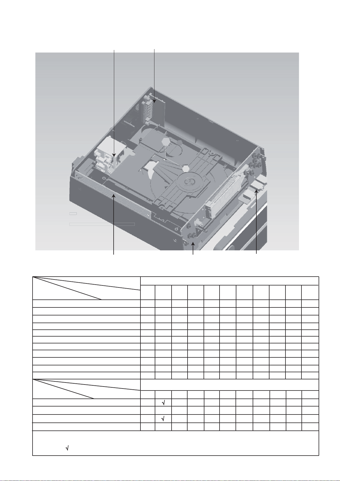
VERSION VARIATION
Board in used:
LCD DISPLAY BOARD
HEADPHONE BOARD
POWER BOARD
DECODER BOARD
S
:
Type /Versions:
Service policy
SCART BOARD
Type /Versions:
Features
RDS
VOLTAGE SELECTOR
ECO STANDBY - DARK
TDS
* TIPS : C -- Component Level Repai r.
M -- Module Level Repair
-- Used
Feature diffrence
LCD Display Board USB/Headphone Board
MCD122
/05
/05
/12
C
M
M
M
M
/12
/37
/37
/55
/55
/58
/58
/61
MCD122
/61
/79
/79
/93
C
M
M
M
/93
/94
/94
/96
/96
/98
C
M
M
M
/98
Page 3

Electronic Specification
1-2
AMPLIFIER
Rated Output Power ......................... 2X20W RMS
Signal-to-noise ratio ...................................≥65dBA
Frequency response ............... 20Hz--20kHz ±3dB
Aux Input ................................... 1V/ RMS 16kohm
DISC
Laser Type .................................... Simeconductor
Disc Diameter ....................................... 12cm/8cm
Support Disc ...............................................CD-DA,
CD-R,CD-RW,MP3,DVD,DVD-RW,DVD+RW
Audio DAC .....................................................1KHz
Total Harmonic Distortion .............................. < 1%
Frequency Response ..................... 20Hz ~ 20KHz
S/N Ration ..................................................>65dBA..
TUNER
FM Tuning Range .......................... 87.5--108 MHz
Tuning grid ........................................ 100K/50KHz
Sensitivity
– Mono, 26dB S/N Ratio ................................. 5uV.
– Stereo, 46dB S/N Ration .......................... 100uV
Selectivity ................................................... >33dB
Image Rejection ......................................... >25dB
Total Harmonic Distortion ................................. 3%
Signal to Noise Ration .............................. ≥50dBA
SPEAKERS
Speaker Impedance ............................................ 2x8ohme.
Speaker Driver, base .....................................................4”
Speaker Driver, tweeter ....................................... Buzzer
Frequency Response ................. 100Hz +5dB+/-5 15KHz
GENERAL INFORMATION
Total Output power ...........................................40W RMS
AC Power ......................................................220V / 50Hz...
Operation Power Consumption ................................ 40W
Standby Power Consumption ................................. <6W
Eco Standby Power Consumption .......................... <1W
Headphone Output .................................. 500mV 32ohm.
USB Direct ..................................................... Version 2.0
Dimensions
– Main unit (w x h x d) ............................ 220x90x240mm
– Speaker box (w x h x d) .................... 100x220x160mm
– SUBwoofer(w x h x d) ...............................................NA
Weight
– With Packing .......................................................... 6KG
– Main Unit ...........................................................1.65 KG
– Speaker box .....................................................1.5x2KG
– SUBwoofer............................................................... NA
Specifications and external appearance are
subject to change without notice.
Page 4
e
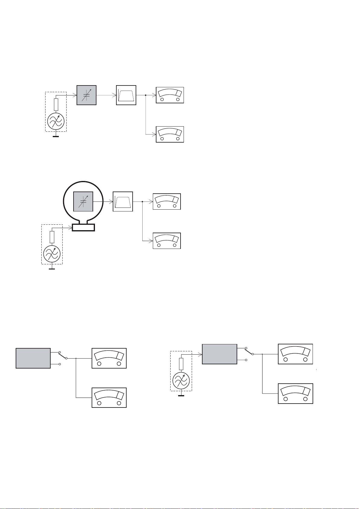
MEASUREMENT SETUP
Tuner FM
1-3
Bandpass
LF Voltmeter
e.g. PM2534
RF Generator
e.g. PM5326
DUT
250Hz-15kHz
e.g. 7122 707 48001
Ri=50:
S/N and distortion meter
e.g. Sound Technology ST1700B
Use a bandpass filter to eliminate hum (50Hz, 100Hz) and disturbance from the pilottone (19kHz, 38kHz).
Tuner AM (MW,LW)
RF Generator
e.g. PM5326
Ri=50:
DUT
Frame aerial
e.g. 7122 707 89001
Bandpass
250Hz-15kHz
e.g. 7122 707 48001
LF Voltmeter
e.g. PM2534
S/N and distortion meter
e.g. Sound Technology ST1700B
To avoid atmospheric interference all AM-measurements have to be carried out in a Faraday´s cage.
Use a bandpass filter (or at least a high pass filter with 250Hz) to eliminate hum (50Hz, 100Hz).
CD
Use Audio Signal Disc
(replaces test disc 3)
DUT
L
R
SBC429 4822 397 30184
S/N and distortion meter
e.g. Sound Technology ST1700B
LEVEL METER
e.g. Sennheiser UPM550
-
Recorder
Use Universal Test Cassette CrO2 SBC419 4822 397 30069
or Universal Test Cassette
LF Generator
e.g. PM5110
Fe SBC420 4822 397 30071
DUT
L
R
S/N and distortion met
e.g. Sound Technology ST170
LEVEL METER
e.g. Sennheiser UPM550
with FF-filter
Page 5

SERVICE AIDS
1-4
GB
All ICs and many other semi-conductors are
susceptible to electrostatic discharges (ESD).
Careless handling during repair can reduce life
drastically.
When repairing, make sure that you are
connected with the same potential as the mass
of the set via a wrist wrap with resistance.
Keep components and tools also at this
potential.
WARNING
GB
Safety regulations require that the set be restored to its original
condition and that parts which are identical with those specified,
be used
Safety components are marked by the symbol
!
.
ESD
CLASS 1
LASER PRODUCT
Lead free
Page 6
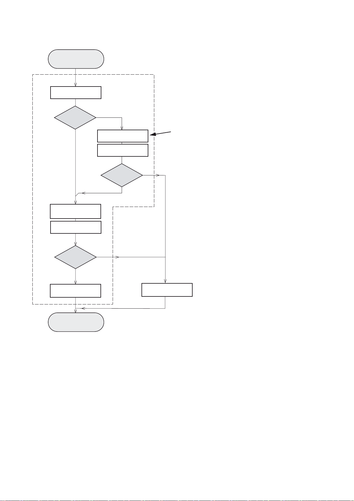
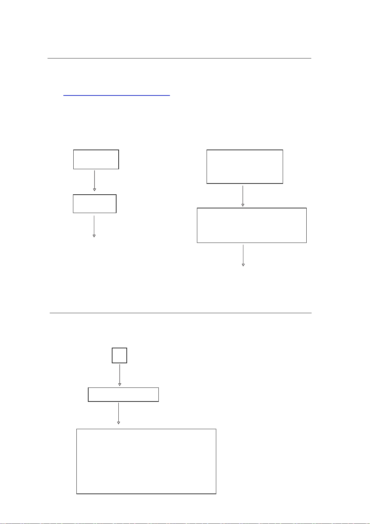
INSTRUCTIONS ON CD PLAYABILITY
Customer complaint
"CD related problem"
Set remains closed!
check playability
1
1-
playability
ok ?
Y
Play a CD
for at least 10 minutes
check playability
playability
ok ?
Y
N
"fast" lens cleaning
check playability
playability
ok ?
N
3
N
Y
For flap loaders (= access to CD drive possible)
cleaning method
4 is recommended
add Info for customer
"SET OK"
2
return set
1 - 4 For description - see following pages
Exchange CDM
Page 7
INSTRUCTIONS ON CD PLAYABILITY
1-
1
PLAYABILITY CHECK
For sets which are compatible with CD-RW discs
use CD-RW Printed Audio Disc ....................7104 099 96611
TR 3 (Fingerprint)
TR 8 (600μ Black dot) maximum at 01:00
• playback of these two tracks without audible disturbance
playing time for: Fingerprint t10seconds
Black dot from 00:50 to 01:10
• jump forward/backward (search) within a reasonable time
For all other sets
use CD-DA SBC 444A..................................4822 397 30245
TR 14 (600μ Black dot) maximum at 01:15
TR 19 (Fingerprint)
TR 10 (1000μ wedge)
• playback of all these tracks without audible disturbance
playing time for: 1000μ wedge t10seconds
Fingerprint t10seconds
Black dot from 01:05 to 01:25
• jump forward/backward (search) within a reasonable time
4
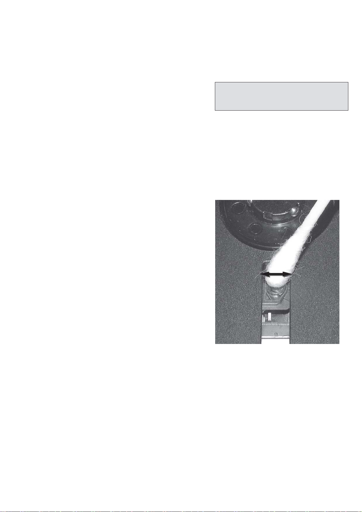
LIQUID LENS CLEANING
Before touching the lens it is advised to clean the
surface of the lens by blowing clean air over it.
This to avoid that little particles make scratches on
the lens.
Because the material of the lens is synthetic and coated
with a special anti-reflectivity layer, cleaning must be done
with a non-aggressive cleaning fluid. It is advised to use
“Cleaning Solvent
The actuator is a very precise mechanical component and
may not be damaged in order to guarantee its full function.
Clean the lens gently (don’t press too hard) with a soft and
clean cotton bud moistened with the special lens cleaner.
The direction of cleaning must be in the way as indicated in
the picture below.
2
CUSTOMER INFORMATION
It is proposed to add an addendum sheet to the set which
informs the customer that the set has been checked
carefully - but no fault was found.
The problem was obviously caused by a scratched, dirty or
copy-protected CD. In case problems remain, the customer
is requested to contact the workshop directly.
The lens cleaning (method 3) should be mentioned in the
addendum sheet.
The final wording in national language as well as the printing
is under responsibility of the Regional Service Organizations.
Page 8
Software Version Check & Upgrade
Upgrade software
1.Download the software from Philips support website:
http://www.philips.com/support
2. Load the CD Disc or USB device with software,Software upgrade procedure
starts automatically
2-1
VFD Display:
LOADING
Upgrading
Waiting a minute
Door Open
Software upgrade finish.
Software version and date check
OR
TV Screen Display:
Software Upgrade
Erasure and Upgrade
OK Cancel
Software Upgrade
Upgrading
Please don’t remove the player power
Waiting a minute
Door Open
Software upgrade finish.
1, In the absence of USB/DISC state or STOP status, press the
“SYSTEM/MENU” on remote control, TV Screen Display:
Select
√
OK
Version Information
OK
BE VER: MCD122/xx Vxx yyyy.mm.dd
FE VER: DE4-MAIN.FE.ASA.01.8B.37
DSP VER: DSP.01
CE VER: ZRXF2.yymmdd
RegionCode: x
MCU VER: Vxx yyyymmdd
Page 9

Malfunction Follow Check Chart
2-2
2-2
No power
Check if the Power Cord
is connected
Y
Check the AC
outlet
No
Y
Check if the Dc output
provided voltage
(about 34.5V)
Y
Check if the Main
Board has provided
voltage
Replace a new
AC Cable
Replace a new
No
Power Board
Replace a new
No
one
No sound
Adjust the volume
Y
Check if the speakers
are connected correctly
Y
Check if the USB or other
devices are connected
Y
Check if the USB or other
devices are incompatible
Y
Check if there is voltage
supplied to the USB Board
No
Time/Clock does not work
Plug in the power cord
Switch on the Timer
Reset the Time/Clock
Replace a
new one
No display
Check the files or folders in
USB or others devices has
not exceeded the certain limit
Check the data wire which
connected the Main Board,
if has provided voltage
Check if the VFD Board
has provided voltage
Check if the Main Board
has provided voltage
Replace the IC PT6311
No
/SC16311/CD16311
No
Replace a new one
Y
Check if the CPU IC
has provided voltage
Replace the
No
Main Board
Check if the CPU IC
has provided voltage
No
Replace the
Main Board
Page 10

Disassembly Diagram
3-1
3-1
A.Open the DVD Door and loose 2 clipps
to remove the door
A
B.Remove the Top-cabinet
B1.Loose 2pcs screws(3 x 6 KB) of both side
near to the back side.
B2.Loose 2pcs screws(3 x 8 Km) of both side
near to the front cabinet.
B3.Loose 1pc screw(3 x10 FA) of the back side.
B2
B1
B3
C.Remove the Power Board
C1.Loose 1pc screw(3 x10 FA) of the back side.
C2.Loose 1pc screw(3 x 8 BA)
C1
C2
F.Loose 2pcs screws(3 x 8 FT)
to remove the Front Cabinet
F
G.Loose 1pc screw(3 x 8 BA)
to remove the Headphone Board
E.Remove Decoder Board
E1.Loose 4pcs screws(3 x 10 FA) of the back side.
E2.Loose 2pcs screws(3 x 10 FA) of the decoder board.
E1
E2
D.Loose 4pcs screws(3 x 10 PWA)
to remove DVD Loader Driver
D
H.Remove the Display Board
H1.Loose 6pcs screws(3 x 8 BA)
H2.Loose 4pcs screws(2 x 8 BT)
G
H2
H1
Page 11

Block Diagram
DM-06BXLX-L2
DVD Loader
CLOSE DOOR
Foryou pick up
OPEN DOOR
M5V
Loader motor drive r
CD5888
M5V
Open/Close Driver
4-1
4-1
M3.3V
M1.8V
M5V
M3.3V
M1.8V
MAIN BOARD
YUV
S-VIDEO
AUX1
FM Antenna 75OHM
IPOD-DIN9
FM RST
M5V
FM
Si4704
or Si4705(RDS)
4052 A,B
M5V
SWITCH
74LV4052
MCU I2C
M5V
ADC
PCM1808
Door Detect
M3.3V
SDRAM
1M * 16
K4S161622C-TC/L70
M3.3V
SERIAL FLASH
1M
AT26DF081A
M3.3V
EEPROM
AT24C02
IIS BUS
Main chipset
ZR36966
4052 A,B
STANDBY
MUTE
ECO_POWER
FM RST
MPEG I2C
15V
AUDIO ML/MR FL&FR
PWM->
ANL-AUDIO
F4558
MCU5VMCU5V
ECO_POWER
M5V
MCU5V
8550
COAXIAL
AV
MUTE
STANDBY
15VA15V
FL&FR
MUTE
STANDBY
15V
5V
HEAD PHONE L&R
POWER AMP
TDA1517
5W + 5W
POWER1
POWER2
5W at 10%
1
2
1
2
5W at 10%
FL SPK
FR SPK
AC110 / 220
MCU I2C
FM RST
4052 A,B
MPEG I2C
STANDBY
ECO_POWER
MCU5V
MUTE
LCD driver&MCU&RTC
ZX935P-107
DISPLAY BOARD
USB
IR
POWER
LCDKEY
MP3 LINE IN
MCU5VMCU5V
HEAD PHONE
Page 12

Wiring Diagram
4-2
LCD Display Board
4-2
Power Board
Headphone USB Board
DVD Loader Driver
Decoder Board
Page 13

Small Board -- Layout & Circuit Diagram
5-1
5-1
CN1003
4PIN/2.0
5
4
3
2
1
H_OUTL
H_OUTR
H_IN
H_IN
PGND
headphone
J1002C
J1002B
100
100
R101
R100
47K
47K
R1011
R1010
J1002A
USB
CN1000
GND
4
D+
3
D-
2
VBUS
1
4PIN/2.0
MP3 IN
R1005
47K
100P
C1000
R1000
47K
J1000A
C1001
100P
J1001
6
GND
5
Shield
4
GND
3
D+
2
D-
1
vbus
CN1001 2.0/3P
AGND
3
MP3_L
2
MP3_R
1
Page 14

LCD Display Board -- Circuit Diagram
6-1
6-1
R1000
C1000
R1005
C1001
100P
CN1000
GND
4
D+
3
D-
2
VBUS
1
4PIN/2.0
headphone
R101
100
CN1003
47K
47K
CN1001 2.0/3P
R1011
47K
J1002C
H_OUTR
H_OUTL
H_IN
3
4
5
4PIN/2.0
MP3 IN
100P
AGND
3
6
5
4
3
2
1
R1010
PGND
H_IN
2
J1000A
MP3_L
MP3_R
2
J1001
GND
Shield
GND
D+
D-
vbus
USB
J1002A
47K
R100
100
1
1
J1002B
5V
R1006
4.7K
S1000
C1009
15P
REMOTE
C1008
15P
REM1GND2Vcc
3
IR
X1000
32.768
K3
C1002
47U/6.3V
3V
DBB
SW1000
|<<
SW1001
volume+
SW1006
LCD
123456789101112131415161718192021222324252627
com1
seg17
seg18
48
com5
COM5
COM6
seg21
seg19
seg20
47
46
com3
com4
COM3
COM4
45
com2
C1003
C1004
R1012
30K
seg1
seg2
seg3
seg4
C1005
104
3V
104
ECO_POWER
IR
seg5
seg6
K0
seg7
104
seg8
seg9
1
2
3
4
5
6
7
8
9
10
12
seg10
seg11
seg12
11
seg13
seg14
cup2
cup1
VDD3
VDD
VDD1
GND
XOUT
XIN
STB
OSCIN
CLK
IR
seg15
seg16
49
50
com6
com7
COM7
K313K214K115K016STANDBY
17
handshake
SCL
K2
open/close
SW1002
volumeSW1007
>>|
SW1008
K1
standby
SW1003
stop
SW1009
source
SW1010
K0
mode
SW1011
play
SW1012
MUTE
28
com2
com3
com4
com5
com6
com7
seg1
seg2
seg3
seg5
seg6
43
42
41
seg4
39
40
38
44
com1
COM2
SEG7
SEG6
SEG5
SEG4
SEG3
SEG2
SEG1
COM1
SEG8
SEG9
SEG10
SEG11
SEG12
SEG13
SEG14
SEG15
SEG16
SEG17
SEG18
MUTE18DATA19KS220KS121KS022SEG2123SEG20
SEG19
24
25
seg19
seg20
seg21
SDA
KS2
C1014
104
KS1
KS0
LCD
U1000
U1001
seg7
37
seg8
36
seg9
35
seg10
34
seg11
33
seg12
32
seg13
31
seg14
30
seg15
29
seg16
28
seg17
27
seg18
26
ZX935P
CN1002
ECO_POWER
MUTE
GND
SCL
SDA
GND
5V
LED
IR
8P
5V
LED
R1001
10K
R1002
4.7K
R1003
4.7K
Q1000
8050
R1004
10
R1020
56
LED1000
white LE D
Q2
R1007
2K
R1009
100
8550
3V
5V
C1010
104
3
C1011
220U/16V
IN
IC1000
2
GND
OUT
1
C1012
R1014
750
100U/16V
R1015
1.2k
C1013
104
1117-ADJ
LED1001
blue LED
R1008
5V
2.2k
Q1
1
2
3
4
PNP
R1013
1.2K
ECO_POWER
5
6
7
8
9
Page 15

LCD Display Board -- Layout Diagram
6-26-2
Page 16

7-1
Power Board -- Circuit Diagram -- Power part
7-1
L2
10UH
+5VA
D1
R12
1M/1206
R13
1M/1206
CY3
471/250V
D2
1N5408
1N5408
LT2
2.5MH T18
LT1
30MH UU10.5
D7
1N5408
D3
1N5408
CX2
224/275V
CX1
224/275V
C3
68uF/400W
R15 1M/1206
R14 1M/1206
CY2
471/250V
R20
750K 1206
R6
750K 1206
C11
104/50V
C4
22uF/35V
R10
100R 5% 0805
Q10
MMBT2222
R11
33R 5% 1206
Q7
MMBT2907
R52
10R 5% 0805
U1
LD7535
C20
471/50V
C2
103/630V
D6
FR104
R3
68K/1W
D5
FR157
R4
820 0805
R21
100K/1% 0805
CY1
332/250V
Q1
FQPF8N60
R5/R68/R35/R3
1R5 5% 1206
R2
2R2 5% 1206
C19
471/50V
D130 NC
EL817
IC1
R36 1KR 5% 0805
R25
3.3K 5% 0805
C13
102/1KV
R79
33R/1W
C24
104/50V 0805
IC2
CYT431
C14
102/1KV
C64 NC
R37
10K 5% 0805
C1
1000uF/10V
R81
33R/1W
D9
UF5404
D10
UF5404
C18
R44
D14
LL4148
R42
5.1K 1% 0805
C5
1000uF/10V
1000uF/25V
33K 1% 0805
C16
1000uF/25V
F1
T3.15A/250V
CON2
2.5/2P
RT1
MF72 10D-9
Q4
S8050
R19
Q3
D882
330R/1W
C21
1000uF/10V
R27
10K 1206
C44
104/50V 0805 NC
R280
IC4
TL431A
R17
5.1K 0805
R18
5.1K/0805
R38
100K/0805
Page 17

7-2
Power Board -- Circuit Diagram -- Audio Part
R59
10K 0805
C31
47uF/16V
U3
R54
100K/0805
CON4
2.0/4P
C35
220uF/16V
R60
4.7K 0805
R53
22K 0805
R57
10K 0805
C36
220uF/16V
Q11
9014
S08
PT2309
R8
22 0805
C37
220uF/16V
C33
1uF/25V
C32
1uF/25V
C38
C30
1uF/25V
HP-MUTE
104/50V 0805
R56
4.7K 1/4W
R55
4.7K 0805
MUTE1
HP-MUTE
VCC
FLIN
FRIN
MUTE1
D12
1N4148
STANDBY
MUTE
FLIN
FRIN
MUTE
R32
10K/1206
R22
1K/0805
R33
10K
R30
8.2K
R23
10K/0805
R29
8.2K
R31
4.7K
C6
1uF/50V
C7
1uF/50V
R24
0
C23
102/50V 0805
+22V
R7
47K/0805
Q5
MMBT2222
R28
4.7K
C22
MODE
R34
1K/1206
Q2
MMBT2222
R45
MODE
R46
470/0805
Q6
MMBT2222
102/50V 0805
D13
1N4148
C9
10uF/25V
10K/0805
C41
224J
C12
224J
R47
270/1206
C8
22uF/25V
1206
C10
2.2uF/25V
Q8
MMET2222
Q9
MMET2222
IC3
TDA8948J
LOUT+
LOUT-
ROUT-
ROUT+
7-2
R50
15K/1206
LOUT+
R9
2.2 1/4W
R51
2.2 1206
R48
2.2 1206
R39
2.2 1206
DZ2
12V
R41
1.5K/0805
ROUT-
R49
10K/1206
LOUT-
ROUT+
C29
104/50V 1206
C28
104/50V 1206
C26
104/50V 1206
C25
104/50V 1206
C27
104/50V 1206
+18V
D15
1N4148
Page 18

Power Board -- Layout Diagram
7-3 7-3
Page 19

Decoder Board -- Circuit Diagram -- Part1
8-1
8-1
Serial Flash pinout - for reference
SF_CS
SFDI
R12 4.7KR12 4.7K
DSPVCC33
DSPVCC33
SF_CS
SFCS
Release
Debug
Download
C31
C31
0.1uF
0.1uF
C32
C32
10nF
10nF
Pin1-2 short
Pin2-3 short
Pin1-2 short
C5
C3
C4
1nFC51nF
1nFC31nF
1nFC41nF
Put at the middle of traces.
FB5FB5
C22 10nFC22 10nF
C21 100pFC21 100pF
8
VDD
R10 4.7KR10 4.7K
7
6
SCK
5
For EMI (As Close as possible to U100 )
SFCLK
SFDO
DSPVCC33
I2CDAT I2CCLK
1
2
3
R25
R25
10K
10K
U1
/CS
/HOLD
SO
/WP
GND4SI
MX25L1605DU1MX25L1605D
JP100 JP101
Open
Pin2-3 short
Pin1-2 short
DSPVCC18
DSPVCC18
C34
C34
10nF
10nF
C36
C36
C35
C35
10nF
10nF
+
+
10nF
10nF
EC3
EC3
100uF/10V
100uF/10V
C43
C43
0.1uF
0.1uF
C6
100pFC6100pF
DSPVCC33
R115
R115
10K
10K
C45
C45
10nF
10nF
INSW
DRVSB
IN_OUT_SW
CLOSE
OPEN
HOMESW
C7
100pFC7100pF
R3 1KR3 1K
R5 1KR5 1K
DSPVCC33
C37
C37
10nF
10nF
Important power supply!
Close to
Vaddis
R145 75R1%R145 75R1%
GP-0
GP-0
GP-4
GP-5
GP-3 AIN
C128
C128
100pF
100pF
VDDAFE
VDDDAC
VDDPLL
R148 75R1%R148 75R1%
R150 75R1%R150 75R1%
C134
C134
100pF
100pF
VDDPWM
R152 75R1%R152 75R1%
GP-0
GP-3
GP-4
GP-5
C_B_U
Y_R_V
CVBS_C
CVBS_G_Y
APWM_RAPWM_L-
AMCLK
ALRCLK
ABCLK
AIN
USB
C11
C11
10nF
10nF
C96
C96
10nF
10nF
C_B_U
Y_R_V
CVBS_C
CVBS_G_Y
+5V
C1
10nFC110nF
C12
C12
10nF
10nF
C20
C20
1nF
1nF
USB_DN USB_DN1
USB_DP
INSW
DRVSB
IN_OUT_SW
CLOSE
OPEN
HOMESW
C8
1nFC81nF
Close to Vaddis!
SPDL_SENS-
RF_B
RF_A
RF_F
SPDL_SENS+
RF_E
FOCUS_PWM
TRACK_PWM
SPDL_PWM
C19
C19
1nF
1nF
STROBE
CLK
U2AU2A
103
Gen_4/VID7
104
SFCS
105
GND
106
SFDO/RS_SF
107
SFDI/RS128_Bootsel2
108
VDDC
109
VDDP
110
SFCLK/RS128_Bootsel1
111
GPIO[5]
112
SD_D/IGPIO[7]
113
PWM5
114
SD_CMD/GPIO[6]
115
SD_CLK/IGPIO[7]
116
VDDP
117
DP
118
DN
119
RAMADD[4]
120
RAMADD[3]
121
RAMADD[5]
122
VDDIP
123
RAMADD[2]
124
RAMADD[6]
125
RAMADD[1]
126
RAMADD[7]
127
VDDC
128
GND
U3
U3
SLED_PWM
R7 220RR7 220R
STROBE
CLK
RAMADD5
RAMADD6
RAMADD9
RAMADD4
RAMADD7
RAMADD8
31A730A629A528A427
26
VSS
K4S161622C-TC/L70
K4S161622C-TC/L70
VDD
23A324
25
RAMBA
RAMADD3
RAMADD10
RAMADD0
RAMADD1
RAMADD2
A932A8
BA19A10/AP20A021A122A2
RAMADD0
33
18
RAMCS0-
102
Gen_5/GPIO[0]
RAMADD[0]1RAMADD[8]
2
RAMADD8
RAMCKE
34
NC
CKE
CS
RAS
17
RAMRAS-
FPC_STB
FPC_CLK
SLED_PWM
TRACK_PWM
SPDL_PWM
DUPTD0/FPC_CLK
CD_DVD_1
HOMESW
FPC_STB
DRVSB
VDDPWM
94
101
Gen_6
92
100
98
97
96
95
93
91
VDDP
VDDC
Gen_799Gen_8
Gen_9
Gen_11
Gen_12/VID0
GPIO[51]/PWMCO[2]/FIELD
GPIO[52]/PWMCO[3]/HSYNC
GPIO[50]/PWMCO[1]/VCLKx2
Vaddis-966XE
RAMADD[10]3VDDP4RAMADD[9]5RAMCS0#
RAMADD[11]/GPO[64]6RAMBA8RAMRAS#10RAMCS1#/GPO[65]9RAMCAS#11RAMWE#13RAMDQM14GNDPCLK15PCLK16VDDP
7
12
RAMADD11
RAMCAS-
RAMRAS-
RAMCS1-
RAMBA
RAMWE-
RAMCS0-
RAMADD10
RAMADD9
RAMDQM
PCLK
36
35
CLK
UDQM
CAS
WE
14
16
15
RAMDQM
RAMWE-
RAMCAS-
RAMDQM
RAMDAT11
RAMDAT12
RAMDAT13
RAMDAT10
RAMDAT8
RAMDAT9
39
38NC37
44
42
41
45
DQ940DQ8
DQ1143DQ10
VSSQ
VDDQ
VDDQ
DQ4
VSSQ10DQ611DQ7
DQ36VDDQ
DQ5
VDDQ13LDQM
9
7
8
12
RAMDAT7
RAMDAT4
RAMDAT2
RAMDAT3
RAMDAT5
RAMDAT6
LD_CD
LD_DVD
MD_CD
MD_DVD
MD_CD
LD_CD
LD_DVD
MD_DVD
FOCUS_PWM
85
90
86
87
88
89
CD_LD
CD_MD
DVD_LD
DVD_MD
VDDPWM
GPIO[49]/PWMCO[0]
VDDPCLK17RAMDAT[8]18RAMDAT[9]20RAMDAT[7]
19
RAMDAT8
RAMDAT7
IPCLK
RAMDAT14
RAMDAT15
50
47
48
VSS
DQ1549DQ14
DQ1346DQ12
VSSQ
VDD1DQ02DQ13VSSQ4DQ2
5
RAMDAT0
RAMDAT1
FPC_STBINSW
FPC_CLKIN_OUT_SW
R119 10KR119 10K
IPOD_DETECT
DSPVCC18
DSPVCC33I
C85
C85
10pF
10pF
SFCS
SFDO
SFDI
SFCLK
I2CCLK
I2CDAT
FM-RST
IPCLK
C41
C41
10nF
10nF
DSPVCC33IDSPVCC33I
C52
C52
10nF
10nF
R14 33RR14 33R
R15 33RR15 33R
R17 33RR17 33R
R18 33RR18 33R
R28
R28
56R
56R
PCLKPCLK
FB7
FB7
MBW2012-221
MBW2012-221
C42
C42
10nF
10nF
DATA
USB_DP
USB_DN
RAMADD4
RAMADD3
RAMADD5
RAMADD2
RAMADD6
RAMADD1
RAMADD7
+
+
EC5
EC5
100uF/10V
100uF/10V
I2CCLK
I2CDAT
DSPVCC33
MBW2012-221
MBW2012-221
DATA
R116
R116
10K
10K
SDRAM3.3V
C38
C38
C39
C39
C40
C40
10nF
10nF
10nF
10nF
10nF
10nF
C47
C47
C49
C49
C51
10nF
10nF
C51
10nF
10nF
10nF
10nF
FB8
FB8
SFCS_0
SFDO_0
SFDI_0
SFCLK_0
CD_DVD
CD_DVD
DSPVCC33
VDDAFE
84
RAMDAT9
83
GNDREF
VDDSAFE
RAMDAT[6]
21
RAMDAT6
VC
R4 15.4K(1%)R4 15.4K(1%)
C16 0.1uFC16 0.1uF
RESOUT
VC
VREF
82
80
81
VC
VREF
RESOUT
RAMDAT[10]
RAMDAT[5]
RAMDAT[11]24RAMDAT[4]25RAMDAT[3]27RAMDAT[12]26VDDIP28RAMDAT[13]29RAMDAT[14]32RAMDAT[2]
23
22
RAMDAT5
RAMDAT11
RAMDAT10
SDRAM3.3V
SDRAM3.3V
SPDL_SENS+
RF_F
RF_E
SPDL_SENS-
76F77J74E75
78
79
K
VFE_YIN
GND1AFE
30
RAMDAT3
RAMDAT13
RAMDAT4
RAMDAT12
RAMDAT2
RAMDAT15
53
54
VSS
DQ15
U7
U7
VDD1DQ02VDDQ
RAMDAT0
C13 1nFC13 1nF
RF_C
RF_D
C14 1nFC14 1nF
RFP
RFN
RF_A
RF_D
RF_C
RF_B
VDDAFE
VDDAFE
71
68A69
70
72
73
67
66
65
B
D
C
RFP
RFN
VDDAFE
VDD1AFE
GNDDACBS2
GPIO[43]/DUPRD0/TDO/SSCTXD
GPIO[29]/AMCLK/APWM0-
GPIO[25]/AOUT2/APWM3-
GPIO[24]/DUPRD1/ALRCLK/APWM4-
IGPIO[23]/DUPTD1/ABCLK/APWM5-
RAMDAT[1]33RAMDAT[15]34RAMDAT[0]
VDDC31VDDP36GNDAPWM
VDDAPWM
35
37
38
VDDAPWM
RAMDAT1
RAMDAT14
RAMDAT15
RAMDAT0
RAMDAT11
RAMDAT10
RAMDAT9
RAMDAT13
RAMDAT12
RAMDAT14
51
52
VSSQ
3
48
49
DQ1350DQ14
VDDQ
NM
NM
K4S641632H-UC70]
K4S641632H-UC70]
DQ14DQ25VSSQ6DQ37DQ4
RAMDAT2
RAMDAT1
RAMDAT3
43
44
45
46
DQ9
DQ1147DQ12
DQ10
VSSQ
VDDQ
VDDQ9DQ5
DQ611VSSQ12DQ713VDD14DQML
8
10
RAMDAT5
RAMDAT4
RAMDAT6
GPIO[32]/SPDIFO
GPIO[28]/APWM1GPIO[26]/APWM2-
3.30V
C27
C27
0.1uF
0.1uF
Close to pin 38
RAMDQM
PCLK
RAMDAT8
38
39NC40
41
42
VSS
DQ8
DQMH
WE#16CAS#
15
17
RAMDQM
RAMDAT7
RAMWE-
RAMCAS-
RSET
DAC1
VDDDAC
DAC2
DAC3
VDDDAC
DAC4
GNDC
VDDPLL
GNDPLL
RESET#
VDDC
VDDP
IGPIO[44]
VDDP
RAMCKE
37
CLK
CKE
RAS#
18
RAMCS1-
RAMRAS-
RF
XIN
XO
GND
R27 100RR27 100R
+
+
EC2
EC2
220uF/6.3V
220uF/6.3V
RAMADD9
RAMADD8
RAMADD11
34
35NC36
A833A9
A11
CS#19BA020BA121A1022A0
RAMADD10
RAMCS0-
RAMBA
C15
C15
33pF
33pF
64
63
62
61
60
59
58
57
56
55
54
53
52
51
50
49
48
47
46
45
44
43
42
41
40
39
ICE
RAMADD7
RAMADD5
RAMADD6
RAMADD4
31A732
A6
A1
23
24A225A326
RAMADD3
RAMADD1
RAMADD0
RAMADD2
RF
R16
R16
392 Ohm 1%
392 Ohm 1%
VDDDAC
VDDDAC
OSCIN
OSCOUT
VDDPLL
RESET#
IRRCV
DUPRD0/FPC_DOUT
R21 100RR21 100R
R117 100RR117 100R
DSPVCC33
XXmA
OPEN
FPC_STB
DUPTD0/FPC_CLK
DUPRD0/FPC_DOUT
28A429A530
VSS
VDD
27
IRRCV
S/PDIF_OUT
FB19 MBW2012-1KFB19 MBW2012-1K
FB27 MBW2012-1KFB27 MBW2012-1K
FPC_DOUT
S/PDIF_OUT
External 2ch Audio DAC amd ADC
ICETMS
ICETDI
ICETCK
ICETDO
FB1
FB1
MBW2012-221
MBW2012-221
FB2
FB2
MBW2012-221
MBW2012-221
+
+
EC23
EC23
100uF/10V
100uF/10V
FB3
FB3
MBW2012-221
MBW2012-221
FB4
FB4
MBW2012-221
MBW2012-221
EC111
EC111
+
+
220uF/6.3V
220uF/6.3V
FB6 MBW2012-221FB6 MBW2012-221
R29 27RR29 27R
USB_DP1
R30 27RR30 27R
R31
R31
15K
15K
VDDAFE
DSPVCC33
DSPVCC33
DSPVCC18
500mA for device
R32
R32
15K
15K
Crystal
Use it to connect the shell of the crystal with ground.
OSCOUT
R1 75RR1 75R
OSCIN
RESET
R37
R37
10K
10K
RAMCKE
C29
C29
C28
C28
0.1uF
0.1uF
C30
C30
56pF
56pF
56pF
56pF
DSPVCC33
C25
C25
1nF
1nF
SDRAM3.3V
PH1PH1
R2
220KR2220K
R9
4.7KR94.7K
RESET#
+
+
EC1
EC1
22uF/16V
22uF/16V
CN1
CN1
1
2
3
4
2.0-4P
2.0-4P
1
.
C2 22pFC2 22pF
Y1
27.000MHzY127.000MHz
C9 22pFC9 22pF
Close to Vaddis!
Page 20

Decoder Board -- Circuit Diagram -- Part2
Close to CN201
EMC
DVDLD
CN201 is used for Sanyo/Samsung/Sony OPUs
CN3
CN3
24Pin OPU connector
24Pin OPU connector
24
GND-LD
23
DVD-LD
22
NC
21
HFM
20
MD
19
CD-LD
18
VR-DVD
17
VR-CD
16
NC
15
E
14
VCC
13
VC(VREF)
12
GND/PD
11
F
10
B
9
A
8
RF
CD/DVD_SW
7
6
D
5
C
4
T-
3
T+
2
F+
1
F-
GND25GND26GND27GND
28
TP25TP25
C54
C54
NM
NM
[470pF]
[470pF]
OPU5V
VC1
TACTTACT+
FACT+
FACT-
C58
C58
1nF
1nF
C61
C61
0.1uF
0.1uF
CDLD
C55
C55
NM
NM
[470pF]
[470pF]
TP24TP24
C59
C59
1nF
1nF
DVDLD
OPU_HFM
CDLD
VR_DVD
VR_CD
TP26TP26
C62
C62
0.1uF
0.1uF
BT2907Q1BT2907
BT2907Q2BT2907
E
L1 10uHL1 10uH
R51 33RR51 33R
F
B
A
D
C
TP6TP6
TP7TP7
TP8TP8
TP9TP9
TP14TP14
EC9
EC9
+
+
47uF/16V
47uF/16V
TP18TP18
TP19TP19
DSPVCC33
R38
R38
+
EC6
+
EC6
3.3R
3.3R
220uF/6.3V
220uF/6.3V
23
Q1
1
DSPVCC33
+
+
EC7
EC7
R45
R45
3.3R
3.3R
220uF/6.3V
220uF/6.3V
23
Q2
TP12TP12
TP13TP13
TP20TP20
TP21TP21
TP11TP11
TP10TP10
1
TP22TP22
TP17TP17
2.1V
TP16TP16
TP15TP15
R49 220RR49 220R
TP23TP23
C60
C60
1nF
1nF
8-2
C56
C56
0.1uF
0.1uF
R40 220RR40 220R
R50 0R [300R]R50 0R [300R]
RF_E
VC
RF_F
RF_B
RF_A
RF
RF_D
RF_C
In servo 3.3V power supply circuit:
R38,EC6,C56,R45,EC7
need to be closed up when do
layout
LD_DVD
OPU HD65PS Others
R38: 3.3R 4.7R
R45: 3.3R 4.7R
LD_CD
R50=300R, for HOP1200W only
RFA5V
+
+
EC8
EC8
220uF/6.3V
220uF/6.3V
RFA5V
R52
R52
3.3K
3.3K
CD_DVD
M5V
PDIC Control:
DVD=LOW
CD=HIGH
CD_DVD
+
+
EC10
EC10
220uF/6.3V
220uF/6.3V
OPU R41 R39
Sony310 100R 100R
DL3 0 0
IAT510 100R 100R
TOP1100S 10R 10R
SEMCO-SP1 0 0
MITSM820W 91R 91R
HD8(DV23) 0 0
HOP1200W NM NM
HD65/HD62 0 0
502W 91R 91R
Arima681 NM NM
OPU R46 R47
HOP1200W 100R 100R
Arima681 100R 100R
Others NM NM
FOCUS_S
3V3_DRV
1V8_FB
SLED_S
3V3_FB
OPEN
OPEN
CLOSE
CLOSE
LOAD-
C63
C63
LOAD+
0.1uF
0.1uF
SL_MOT+
SL_MOT-
FACT-
FACT+
U4
U4
CD5888CB(1.18V)
CD5888CB(1.18V)
1
VINFC
2
CFCERR1(TRB_1)
3
CFCERR2(REGO2)
4
VINSL+
5
VINSL-(REGO1)
6
VOSL(FWD)
7
VNFFC(REV)
8
VCC
9
PVCC1(LOAD-)
10
PGND(LOAD+)
11
VOSL-(VOSL+)
12
VOSL+(VOSL-)
13
VOFC-
14
VOFC+
VR_CD
VR_DVD
CTKERR1(TRB_2)
CTKERR2(NC)
PGND(VCC2)
GND29GND1
30
STBY
BIAS
VINTK
VINLD
PREGND
PVCC2
VNFTK(NC)
VOLD-
VOLD+
VOTK-
VOTK+
8-2
MD_DVD
R41
R41
0R
0R
[NM]
[NM]
R47
R47
NM
NM
[91R]
[91R]
VC2
TRACK_S
1V8_DRV
SPDL_S
SP_M-
SP_MOT+
TACT-
TACT+
MD_CD
DRVSB
M5V
R39
R39
0R
0R
[NM]
[NM]
R46
R46
NM
NM
[91R]
[91R]
28
27
26
25
24
23
22
21
20
19
18
17
16
15
BEMF
Current Type(Default)
SP_M-
SP_MOT-
FOCUS_S
TRACK_S
SPDL_S
SLED_S
R42 2KR42 2K
R43
R43
R44
R44
2.2R
2.2R
2.2R
2.2R
R48 2KR48 2K
Close to Vaddis!
C64
C64
1nF
1nF
SPDL_SENS-
D1
C66
C66
27nF
27nF
C67
C67
27nF
27nF
2
1
BAT54CD1BAT54C
SPDL_SENS+
R53 51KR53 51K
R54 51KR54 51K
R55 22KR55 22K
R56 51KR56 51K
C57
C57
0.1uF
0.1uF
C65
C65
1nF
1nF
SPDL_SENS-
DSPVCC33
3
SPDL_SENS+
FOCUS_PWM
TRACK_PWM
SPDL_PWM
SLED_PWM
CN5
CN5
SLED-
SLED+
HOMESW
GND
SP+
6P/2.0
6P/2.0
CN6
CN6
LOAD+
LOAD-
OUTSW
GND
INSW
5P/2.0
5P/2.0
M5V
FB25
FB25
FB/0805
FB/0805
DSPVCC33
R57
R57
4.7K
4.7K
HOMESW
HOMESW
+
+
EC11
EC11
100uF/10V
100uF/10V
C70
C70
33pF
33pF
IN_OUT_SW
C71
C71
33pF
33pF
INSW
SL_MOTSL_MOT+
HOMESW
SP_MOT+
SP_MOT-
C72
C72
33pF
33pF
IN_OUT_SW
INSW
6
5
4
3
2
1
SP-
C68
C68
C69
C69
33pF
33pF
33pF
33pF
For EMI,Close to CN203
LOAD-
1
LOAD+
2
3
4
5
EC4
EC4
+
+
100uF/10V
100uF/10V
+
+
EC14
EC14
220uF/6.3V
220uF/6.3V
3V3_DRV
3V3_FB
12
D2
HER204D2HER204
D3 1N4001D3 1N4001
23
Q3
1
SS8550Q3SS8550
R60
R60
1.8K(1%)
1.8K(1%)
R63
R63
1.1K(1%)
1.1K(1%)
12
1V8_DRV
1
1V8_FB
23
Q4
SS8550Q4SS8550
R61
R61
430R(1%)
430R(1%)
R64
R64
1K(1%)
1K(1%)
S8050/S8550
2 E
1 B
3 C
DSPVCC18DSPVCC33
Q210, 211 must have
enough large pads
for thermal spreading
V81.1V81.1
Close to motor driver.
VC2
C73
C73
0.1uF
0.1uF
R58
R58
1K(1%)
1K(1%)
R62
R62
1K(1%)
1K(1%)
DSPVCC33
R59
R59
33K
33K
C74
C74
0.1uF
0.1uF
Motor driver R63 R60 R61
CD5888(1.18V) 1K 1% 1.8K 1% 510R 1%
AM5888 1.2K 1% 2K 1% 430R 1%
Page 21

Decoder Board --Circuit Diagram -- Part3
J4
L_AUX2_IN
1
R_AUX2_IN
2
3
PH-3AJ4PH-3A
TO AUX2 INPUT
R170
R_IPOD_IN
R96 10KR96 10K
R_AUX1_IN
R70 10KR70 10K
R_AUX2_IN
R260 10KR260 10K
L_FM
L_IPOD_IN
R99 10KR99 10K
L_AUX1_IN
R138 10KR138 10K
L_AUX2_IN
R146 10KR146 10K
R_FM
CN205
CN205
AV2-8.4-13
AV2-8.4-13
L_AUX1_IN
3
R_AUX1_IN
2
AGND
1
TO AUX1 INPUT
NC(CM1214-01ST)
NC(CM1214-01ST)
I2CCLK
I2CCLK
I2CDAT
I2CDAT
R170
4.7K
4.7K
100pF
100pF
D4
D4
FB23 FB/2KFB23 FB/2K
FB24 FB/2KFB24 FB/2K
C119
C119
R171
R171
4.7K
4.7K
R167
R167
4.7K
4.7K
21
C120
C120
100pF
100pF
R172
R172
4.7K
4.7K
R168
R168
4.7K
4.7K
FB10
FB10
C101 1uFC101 1uF
C97 1uFC97 1uF
C114 1uFC114 1uF
C115 1uFC115 1uF
C102 1uFC102 1uF
C116 1uFC116 1uF
C126 1uFC126 1uF
C127 1uFC127 1uF
R169
R169
4.7K
4.7K
E1
E1
ANTENNA_1
ANTENNA_1
10nH
10nH
C98 3.3pFC98 3.3pF
FB11 270nHFB11 270nH
C99 100pFC99 100pF
FM-RST
R_DATA
AUDIO_VCC
R377
R377
NC(1K)
NC(1K)
MUTE-APMUTE_CTL
8-3
EC19
EC19
+
+
10uF/25V
10uF/25V
EC20
EC20
+
+
10uF/25V
10uF/25V
D8 1N4148D8 1N4148
12
R73 1KR73 1K
R69 1KR69 1K
R71
R71
10K
10K
R93 1KR93 1K
R80 1KR80 1K
R82
R82
10K
10K
LMAIN-OUT
RMAIN-OUT
MUTE
C135
C135
4.7uF
4.7uF
MUTE
MUTE
R72 1KR72 1K
R83 1KR83 1K
LMAIN-OUT
RMAIN-OUT
8-3
VCC5
APWM_L-
C110
C110
0.1uF
0.1uF
S1
S0
RIGHT1-IN
RIGHT2-IN
RIGHT3-IN
ENABLE
R9010K R9010K
9
10
1
5
2
4
12
14
15
11
U27
U27
74HC4052
74HC4052
10
1
2
3
4
5
6
7
8
9
S1
S0
B0
B1
B2
B3
A0
A1
A2
A3
ENABLE
NC
FMI
RFGND
TXO
RST
SEN
SCLK
SDIO
RCLK
VIO
U9
SI4705U9SI4705
S1
S0
LEFT1-IN
LEFT2-IN AP-R-OUT
LEFT3-IN
16
VCC
BN
AN
VEE7E6GND
8
21
GPIO1
GND
IRQ/GPIO2
DCLK/GPIO3
DOUT
ROUT
R94 51RR94 51R
DFS
LOUT
GND
VDD
R159
R159
47K
47K
R164
R164
R163
R163
47K
47K
47K
47K
3
13
D5V
FB9 MBW2012-221FB9 MBW2012-221
R86
20
NC
19
18
17
16
15
14
13
12
11
R86
NC(0R)
NC(0R)
+
+
EC22
EC22
100uF/10V
100uF/10V
R9210R R9210R
R165 51KR165 51K
C100
C100
0.1uF
0.1uF
R-IN
L-IN
FM5V
+
+
EC12
EC12
100uF/10V
100uF/10V
FM5VR_CLACK
L_FM
R_FM
C94
C94
0.1uF
0.1uF
2.0*5PINJ82.0*5PIN
J8
AP-L-OUT
1
AP-R-OUT
2
3
MUTE-AP
4
POWER_ON_OFF
5
AUDIO_VCC VCC5
VDDAPWM
POWER_ON_OFF
APWM_R-
R376
R376
10K
10K
OP
R118
R118
100K
100K
R79 680ER79 680E
R105 6800ER105 6800E
+
+
EC18
EC18
100uF/10V
100uF/10V
R77 39KR77 39K
R67
R67
39K
39K
D303
D303
5.1V
5.1V
1 2
R65 82KR65 82K
R68 4.7KR68 4.7K
C77
C77
1.2nF
1.2nF
R75 82KR75 82K
R78 4.7KR78 4.7K
C87
C87
1.2nF
1.2nF
MUTE_CTL
MUTEA
+
+
EC26
EC26
47uF/16V
47uF/16V
OP
C79
C79
0.1uF
0.1uF
OP
C76 75pFC76 75pF
-
-
OP-
2
+
+
OP+
3
84
C86 75pFC86 75pF
-
-
OP-
6
+
+
OP+
5
8 4
C95
C95
4.7uF
4.7uF
D6 1N4148D6 1N4148
D7 1N4148D7 1N4148
MUTEA
C104
C104
0.1uF
0.1uF
U5A
U5A
CF4558
CF4558
1
AUDIO_VCC
U5B
U5B
CF4558
CF4558
7
C93
C93
0.1uF
0.1uF
12
12
1
1
AP-L-OUT
LMAIN-OUT
Q5
3904Q53904
23
RMAIN-OUT
Q6
3904Q63904
23
CN401
CN401
1
2
3
4
5
6
7
8
9
10
11
2.0-11PIN
2.0-11PIN
SCART
Y-Pr_OUT
G-Y_OUT
C-Pb_OUT
EC112
EC112
220uF/6.3V
220uF/6.3V
CVBS_OUT
SCART_SWITCH
AUDIO/TV/16:9
LMAIN-OUT
RMAIN-OUT
C451
C451
100pF
100pF
C452
C452
100pF
100pF
C105
C105
22pF
22pF
DSPVCC33
+
+
32.768KHz
32.768KHz
C53
C53
10nF
10nF
CVBS_OUT
Y-Pr_OUT
G-Y_OUT
C-Pb_OUT
For EMI
R101
C106
C106
22pF
22pF
C107
C107
22pF
Y2
Y2
R104
R104
10R
10R
22pF
VCC5
AMCLK AIN
FB12 MBW2012-221FB12 MBW2012-221
AMCLK
ALRCLK
R101
NC(0R)
NC(0R)
R102
R102
100R
100R
C130 10uF/0805C130 10uF/0805
C129 0.1uFC129 0.1uF
FS1
R448
R448
10K
10K
1
2
3
4
5
6
7
SCART config circuit
VREF
AGND
VCC
VDD
DGND
SCKI
LRCK
1
C1081uC108
1u
U12
U12
PCM1808PW
PCM1808PW
D5V
Q403
Q403
BT3904
BT3904
2 3
C109
C109
0.1uF
0.1uF
R414
R414
150R
150R
RGB Status
R4161KR416
1K
L_IPOD_IN
R_IPOD_IN
TX
IPOD_DETECT
L-IN
R-IN
R412 33RR412 33R
R_IPOD_IN
L_IPOD_IN
D5V
FPC_DOUT
IPOD_DETECT
AUDIO/TV/16:9SCART_SWITCH
Video Status
C457NCC457
NC
C112 1uFC112 1uF
C103 1uFC103 1uF
C117
C117
1000pF
1000pF
AUDIO_VCC
R411
R411
1.8K
1.8K
1
23
R4101KR410
1K
Q402
Q402
BT3904
BT3904
R121 1KR121 1K
R122 1KR122 1K
C118
C118
1000pF
1000pF
R409
R409
1.8K
1.8K
Q401
Q401
BT3904
BT3904
14
VinR
13
VinL
12
FMT
11
MD1
10
MD0
DOUT
BCK
FS2
FS3
9
8
R449
R449
6.8K
6.8K
R447
R447
6.8K
6.8K
ABCLK
AIN
ABCLKALRCLK
1
23
L_IPOD_IN
R_IPOD_IN
J3NCJ3
NC
1
2
3
4
5
6
IPOD
COAX_SPDIF
TX
L410 0RL410 0R
L411 0RL411 0R
L408 0RL408 0R
R125 0RR125 0R
R124 NCR124 NC
R126 NCR126 NC
L409 0RL409 0R
R127 NCR127 NC
COAX_SPDIF
Y-Pr_OUT
IPOD_DETECT
L_IPOD_IN
R_IPOD_IN P59
C-Pb_OUT
D5V
J5
J5
14
13
12
11
10
5
4
3
P51
1
9
2
6
8
P51
P59
7
DASW-02-9
DASW-02-9
Page 22

Decoder Board -- Circuit Diagram -- Part4
8-4
8-4
STBY5V +5V
POWER_ON_OFF
MBW2012-221
MBW2012-221
CN8
CN8
2.0MM-13P
2.0MM-13P
FB22
FB22
1
2
3
4
5
6
7
8
9
10
11
12
13
C121
C121
NC(100pF)
NC(100pF)
R74 1KR74 1K
C91
C91
2.2uF
2.2uF
STBY5V
C125
C125
NC(100pF)
NC(100pF)
STANDBY STROBE
POWER_ON_OFF
R97 33RR97 33R
R98 33RR98 33R
C122
C122
NC(100pF)
NC(100pF)
Q11
Q11
AO3407
AO3407
R6
10KR610K
1
C131
C131
NC(100pF)
NC(100pF)
R100 NC(10K)R100 NC(10K)
MUTEA
C123
C123
NC(100pF)
NC(100pF)
R81KR8
1K
Q12
Q12
3904
3904
23
C132
C132
NC(100pF)
NC(100pF)
D91N4148 D91N4148
FB15 MBW2012-221FB15 MBW2012-221
12
LED
I2CCLK
I2CDAT
C124
C124
NC(100pF)
NC(100pF)
S/PDIF_OUT
C133
C133
NC(100pF)
NC(100pF)
FB16 MBW2012-221(NC)FB16 MBW2012-221(NC)
FB18 MBW2012-221(NC)FB18 MBW2012-221(NC)
FB17 MBW2012-221(NC)FB17 MBW2012-221(NC)
POWER_ON_OFF
MUTEA
I2CCLK
I2CDAT
R445 150RR445 150R
TJC3-4A
TJC3-4A
CN9
CN9
C410
C410
22pF
22pF
FPC_STB
FPC_DOUT
FPC_CLK
IRRCV
COAX_SPDIFS/PDIF_OUT
CVBS_C
Y_R_V
CVBS_G_Y
C_B_U
COAX_SPDIF
CVBS_C
Y_R_V
CVBS_G_Y
C_B_U
C421
C421
150pF
150pF
C423
C423
150pF
150pF
C425
C425
150pF
150pF
C427
C427
150pF
150pF
FB405 1KFB405 1K
FB406 1KFB406 1K
FB407 1KFB407 1K
FB408 1KFB408 1K
1
1
1
1
L_IPOD_IN
R_IPOD_IN
J9
J9
AV6-8.4-13B
AV6-8.4-13B
C-Pb_OUT
C-Pb_OUT
C78
C78
NC(100pF)
NC(100pF)
G-Y_OUT
G-Y_OUT
C80
C80
NC(100pF)
NC(100pF)
Y-Pr_OUT
Y-Pr_OUT
C82
C82
NC(100pF)
NC(100pF)
CVBS_OUT
C83
C83
NC(100pF)
NC(100pF)
3
5
4
1
6
2
10
8
9
7
POWER_ON_OFF
+18V
R348 4.7KR348 4.7K
R346 1KR346 1K
Y-Pr_OUT
G-Y_OUT
C-Pb_OUT
Q15
Q15
SS8550
SS8550
23
1
R3472KR347
2K
Q313
Q313
1
3904
3904
23
R392 330R/0.5WR392 330R/0.5W
Y-Pr_OUT
G-Y_OUT
C-Pb_OUT
AUDIO_VCC
+
+
EC13
EC13
47uF/16V
47uF/16V
MARK1
.
1
MARK2MARK2
.
1
CVBS_OUT
Y-Pr_OUT
ESD2V
C430
C430
0.1uF
0.1uF
MARK3
1
G-Y_OUT
C-Pb_OUT
R433 2.2KR433 2.2K
R432
R432
3.3K
3.3K
MARK4
.
.
1
LMAIN-OUT
RMAIN-OUT
CVBS_OUT
DSPVCC33
3
D401
D401
BAT54S
BAT54S
2
3
D402
D402
BAT54S
BAT54S
2
3
D403
D403
BAT54S
BAT54S
2
3
D404
D404
BAT54S
BAT54S
2
+
+
EC429
EC429
100uF/10V
100uF/10V
L_IPOD_IN
R_IPOD_IN
+18V
R111
R111
10K
10K
+5V
C428 0.1uFC428 0.1uF
R113
R113
10K
10K
R444 27RR444 27R
R430
R430
82R
82R
STBY5V
4
4
3
3
2
2
1
1
R112
R112
R114
R114
10K
10K
2.2K
2.2K
C111
C111
100pF
100pF
MUTE_CTL
CLOSE
OPEN
ENABLE
MUTE_CTL
CLOSE
OPEN
16
15
14
13
12
11
10
9
VDD
OUTPUT/EN
Q5
Q6
Q7
Q8
Q,s
Qs
+5V
FB20 FB/0805FB20 FB/0805
FB21 FB/0805FB21 FB/0805
U11
U11
CD4094BC
CD4094BC
STROBE
DATA
CLOCK
Q1
Q2
Q3
Q4
Vss
1
2
3
4
5
6
7
8
D5V
U8
U8
CD4094BC
CD4094BC
16
STROBE
VDD
15
14
13
12
QS
11
10
9
OUTPUT/EN
Q5
Q6
Q7
Q8
Q,s
Qs
DATA
CLOCK
STR
1
2
PCK
3
4
Q1
5
Q2
6
Q3
7
Q4
8
Vss
R85 33RR85 33R
R87 33RR87 33R
R88 33RR88 33R
12
D5 1N4148D5 1N4148
R89 3.9KR89 3.9K
STROBE
DATA
CLK
S1
S0
R91
R91
4.7K
4.7K
LED
R95
R95
10K
10K
STROBE
DATA
CLK
S1
S0
D5V
At middle of trace.
STR
QS
PCK
M5V
RFA5V
D5V
C81
C81
0.1uF
0.1uF
C113
C433
C433
0.1uF
0.1uF
FS3
FS1
FS2
C113
10nF
10nF
Page 23

Decoder Board
8-58-5
Page 24

Exploded View
9-1
9-1
Page 25

ACCESSORIES PARTS LIST
996510025643
MCD122/12 MAIN SPEAKER BOX(/12)
D001
996510025647
MCD113 DVD DOOR/ABS
D009
996510025546
MCD113 FUNCTION BUTTON R/ABS
D010NN
10-1
994000004988
994000005166 AC LINE CORD 1.8M(/93)
994000005078
996510018744
996510026289 MCD122/93 DISPLAY BOX(/93)
996510024836
996510025369
996510026288 PRC500-56REMOTE CONTROL 183/98(/93)
996510025765
996510026287 MCD122/93 MAIN SPEAKER BOX(/93)
AC LINE CORD 1.8M (/12/98)
AUDIO SINGLE WIRE W/RCA 1.5M
FM ANT CONNECTOR 1.5m BLACK
PRC500-56REMOTE CONTROL(/12)
PRC500-56 REMOTE CONTROL(/98)
MCD122/98 MAIN SPEAKER BOX(/98)
MECHNICAL&MISCELLANEOUS PARTS
CASING4
D002
D003
D004
D005
D006
D008
D009
D022
996510025544
996510025532
996510025646
996510025539
996510025534
996510025529
996510025549
996510025546
996510025552
FLAT FLEXIBLE CABLE 24PX100
MCD113 DISPLAY LENS/PMMA
MCD113 DVD FRONT CABINET/HIPS
MCD113 FUNCTION BUTTON/ABS
MCD113 DIRECTION BUTTON/ABS
MCD113 CENTER BUTTON/ABS
MCD113 FUNCTION BUTTON-L/ABS
MCD113 FUNCTION BUTTON-R/ABS
MCD113 DVD TOP COVER/HIPS
D023
D023
D023 996510025766 MCD113 DVD BOTTOM CHASSIS/HIPS(/93)
D007
D013
D013
D013 996510026284 POWER BOARD NEP050A-TP-93(/93)
D015
D015
D015 996510026283 DVD DECODER ZMCDA122-93(/93)
D016
D019
N
996510025649
996510025766
996510025652
996510025642
996510025759
996510025651
996510025764
996510025645
996510025536
996510032287
MCD113 DVD BOTTOM CHASSIS/HIPS(/12)
MCD113 DVD BOTTOM CHASSIS/HIPS(/98)
MCD122 HEADPHONE BOARD
POWER BOARD NEP050A-TP(/12)
POWER BOARD NEP050A-TP(/98)
DVD DECODER ZMCD122(/12)
DVD DECODER ZMCDA122(/98)
MCD122 SCART BOARD(/12)
DVD MECHANISM F-8829D+DM3381-0
LCD DISPLAY BOARD(/98/12)
Page 26

10-2
ELECTRICAL PARTS - DISPLAY PCB
D011
D012
D020
IC1
LED1
LED2
S1
SW1
SW10
SW11
SW2
SW3
SW4
SW5
SW6
SW7
SW8
SW9
U1
U2
X1
996510025535
996510025581
996510025554
996510014857
996510025551
996510021107
996510015840
996510000263
996510000263
996510000263
996510000263
996510000263
996510000263
996510000263
996510000263
996510000263
996510000263
996510000263
996510024049
996510032288
996510021097
MCD113 LED BRACKET/HIPS
MCD113 LCD BRACKET/HIPS
MCD113 LIGHT-GUIDE(PMMA)
IC AMC1117-0333J(SMD)
LED 2X5X7 1L2545B12E0DE002(B)
LED D3X4 1L034XW31B0CT201
IR SENSOR 1MA81P36D1TD001
LIGHT TOUCH SWITCH 6X6X5
LIGHT TOUCH SWITCH 6X6X5
LIGHT TOUCH SWITCH 6X6X5
LIGHT TOUCH SWITCH 6X6X5
LIGHT TOUCH SWITCH 6X6X5
LIGHT TOUCH SWITCH 6X6X5
LIGHT TOUCH SWITCH 6X6X5
LIGHT TOUCH SWITCH 6X6X5
LIGHT TOUCH SWITCH 6X6X5
LIGHT TOUCH SWITCH 6X6X5
LIGHT TOUCH SWITCH 6X6X5
LCD DRIVER MODUL ZX935P-302
LCD DISPLAY
CRYSTAL OSCILLATOR 32.768KHZ
Note:
Only these parts mentioned in the list are normal service parts.
versionlist
v1.0 releaseservicemanualof/12/98
v1.1 addservicebomof/93
Page 27

Factory Parts List
11-1
STRAPTINUNIAMDVD21/221DCMTINU
DRAOBYALPSIDDCL311DCM010D
)5080(JW61/165ROTSISERPIHC91R
SERPIHC2R
5p51.PACPIHC4C
0(KV05p401.PACPIHC8C
M700D
DRAOBTRACS221DCM610D
)5080(JW61/10ROTSI
)5080(JW61/10ROTSISERPIHC3R
)5080(JW61/1K2.1ROTSISERPIHC4R
)5080(JW61/1K2.1ROTSISERPIHC6R
)5080(JW61/1057ROTSISERPIHC7R
)5080(JW61/101ROTSISERPIHC71R
)5080(JW61/1001ROTSISERPIHC61R
)5080(JW61/1K01ROTSISERPIHC5R
)5080(JW61/1K01ROTSISERPIHC81R
)5080(JW61/1K2ROTSISERPIHC31R
)5080(JW61/1K7.4ROTSISERPIHC51R
)5080(JW61/1K7.4ROTSISERPIHC12R
)5080(JW61/1K01ROTSISERPIHC02R
)6021(JW4/1K03ROTSISERPIHC1R
OPN)5080(JV0
OPN)5080(JV05p51.PACPIHC5C
R7X)5080(KV05p401.PACPIHC6C
R7X)5080(KV05p401.PACPIHC7C
R7X)508
R7X)5080(KV05p401.PACPIHC9C
R7X)5080(KV05p401.PACPIHC01C
R7X)5080(KV05p401.PACPIHC31C
6X45-MV3.6u74.PACCITYLORTCELE3C
7X55-LV01u001.PACCITYLORTCELE1C
5X3.65-LV61u022.PACCITYLORTCELE2C
)32-
TOS(0508ROTSISNARTPIHC2Q
)32-TOS(C0558ROTSISNARTPIHC1Q
)32-TOS(C0558ROTSISNARTPIHC3Q
DRAOBENOHPDAEH221DC
)6021(JW4/10ROTSISERPIHC22R
)5080(JW61/1K74ROTSISERPIHC21R
)5080(JW61/1K74ROTSISERPIHC41R
R7X)5080(KV05p001.PACPIHC11C
R7X)5080(KV05p001.PACPIHC21C
)3060(JW61/1001ROTSISERPIHC608R
60(JW61/1001ROTSISERPIHC708R
)30
)3060(JW61/1K01ROTSISERPIHC408R
)3060(JW61/1K01ROTSISERPIHC508R
 Loading...