

Philips Maestro DS9600 Service Manual

S
ervice Manu
al
Published by AVS 0639 Service RCS Subject to modification 3104 205 5026-1
MAESTRO
T ABLE OF CONTENTS
Page
Specifications ........................... .......................................................... 1
Mechanical Instructions Set Disassembly.................................... 2
Mechanical Instructions Set Re-assembly................................... 3
Exploded view & Mechanical Parts list............................................ 4
Exploded view - Docking station....................................................... 5
Electrical diagrams - Docking station............................................. 6
Mechanical instructions & Set Disassembly .................................. 7
Mechanical & Electrical Parts list - Docking station..................... 8
TSU9600/00/05/37/79
DS9600

1-1
A. GENERAL REQUIREMENTS
Operating temperature : between 5 °C and 45 °C
Storage temperature : between -25 °C and +70 °C
Atmospheric pressure : 96 K Pa ± 6 K Pa
Relative humidity : between 40 and 80 %
Transmitted code : RC5, RC6, and learnable format
Infrared wavelength: : 950nm ± 50nm.
ESD : with 8 kV applied to the outside, RC placed
on grounded plane, no damage or functional
failures.
Items not mentioned : According UAW-422.
B. ELECTRICAL REQUIREMENTS
Nominal battery voltage : 3.7 V (Li-Ion battery pack)
Operating voltage : +4.2 ® 3.0 V (Li-Ionbattery pack)
: +5V (main adaptor)
Leakage current at nominal : £ 5 mA.
battery voltage (sleep mode)
Battery lifetime : 2 hrs continuous use.
Transmitted intensity on axis : ³ 70mW/Sr.
at nominal battery voltage
T otal opening angle horizontal, : ± 22.5° Ie ³ 12mW/Sr.
vertical at nominal battery voltage
Standby time : 1 day
C. PRODUCT DESCRIPTION
Maestro is a touchscreen LCD remote control with the following key characteristics:
- Colour active matrix touchscreen TFT LCD with white LED backlight
(640x480, 16bit color)
- Backlight brightness control
- LCD refresh rate 60-80 Hz
- Back lighted hard buttons
- Innovative, customizable user interface
- Downloadable universal database
- Smart power management
- IR learning distance: 10…2.5cm @ +-40 degrees
- Learning frequency 17kHz -1MHz.
- Embedded Li-Ion battery with build-in recharger , 2100mAH capacity
- 16-bit Audio DA converter for CD-like sound quality
- USB device for connection with PC
- IEEE 802.1 1b/g WIFI module embedded
- Mono loudspeaker
- 64 MB Flash memory
- 64 Mbytes SDRAM
- 266MHz MX21 Dragonball processor.
2-1
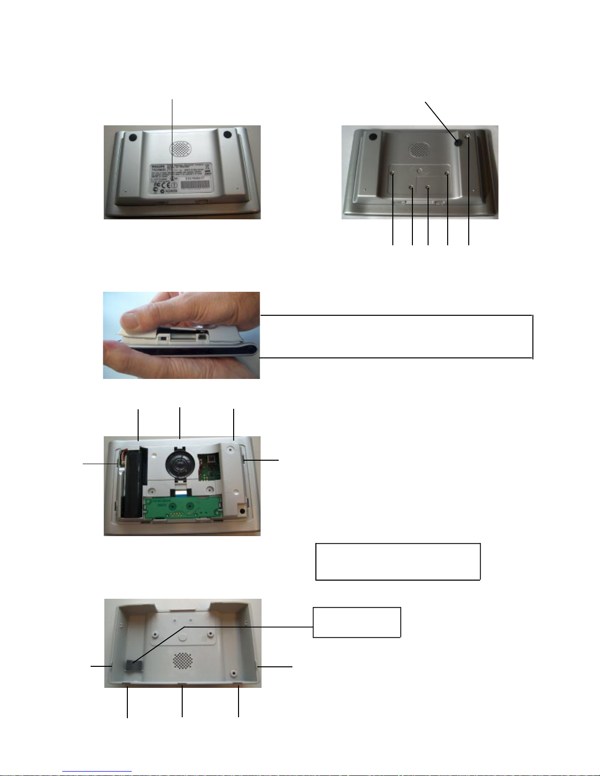
MECHANICAL INSTRUCTIONS
3. Remove 5 x screw (T orx screw M2x10).
Set Disassembly
3. Remove the bottompart cover item 20 by pulling it (bottom side)
on the place as shown in the picture.
3. overview guide holes.
(for info only)
3. overview guideline.
(for info only)
Note that battery is accessible now for replacement !
for replacement see: Set re-assembly on page 3-2
it is recommanded to order the battery (item 251) same
with a new approbation sticker (item 676) and new
rubber feets (item 07).
Battery replacement set: 1 X item 251
1 X item 676
2 X item 07
1. Remove carefully the approbation sticker
item 676 with the help of a label remover.
2. Remove one rubber feet item 07
on the right upper corner to make
the screw accessible.
location of adhesive
Damper item 06
2-2
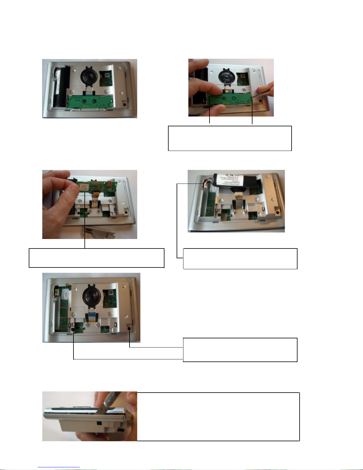
MECHANICAL INSTRUCTIONS
Set Disassembly
5a. Disconnect PB (item 1002) to release the flex-cable
(unlock connector 1003 with the help of a pincet).
5b. Take battery out, disconnect battery plug
(item 251) on connector 1701
4. Remove PB (item 1002) includes docking
insert (item 22) by release the two
“plastic snap hooks” as shown in the picture.
5c. Remove 2 X screws (T orx screw M2X8)
on the position as shown in the picture.
6. - Release bottompart (item 02) from toppart (item 01).
step 1: very important is to start up with one of the “sides”
as shown in the picture.
- Put a sharp knife between toppart and bottompart and use
this as a lever to separate the two parts.
- Important: push up the bottompart compared with the toppart
to unlock the plastic snaps in the holes (bottompart).
2-3
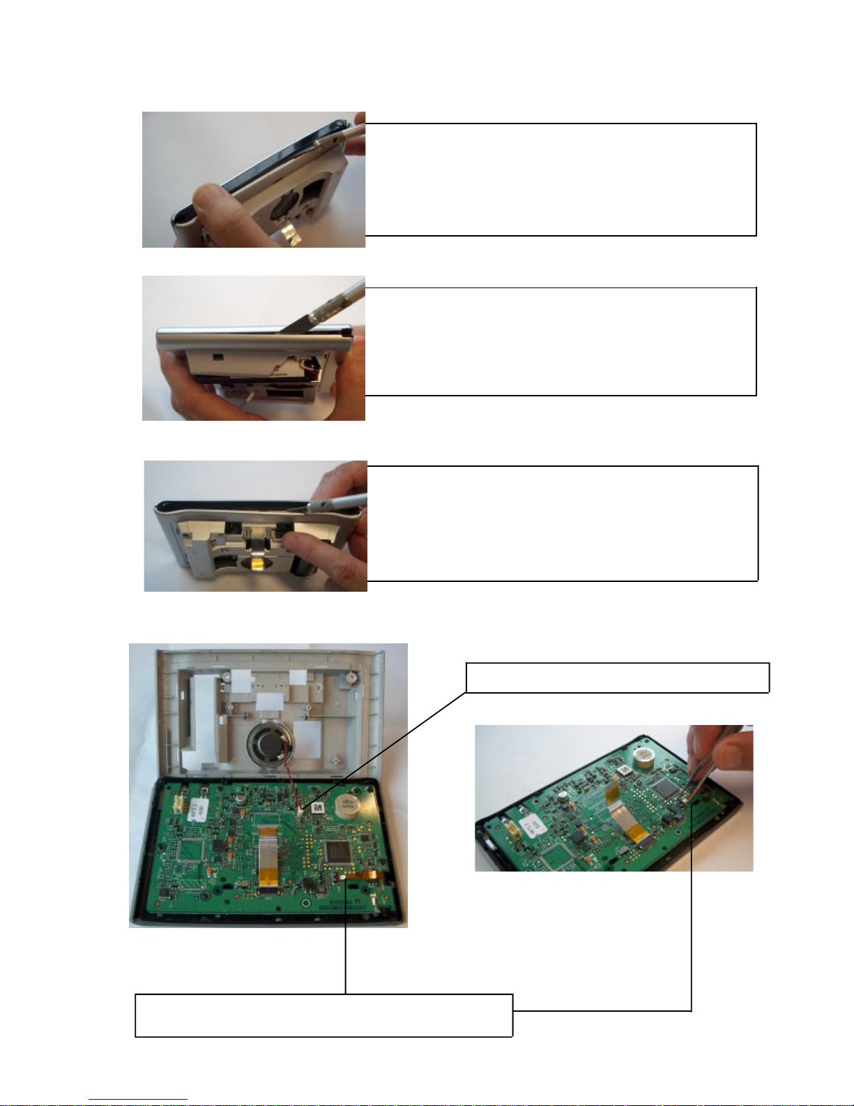
MECHANICAL INSTRUCTIONS
Set Disassembly
7. - Release bottompart (item 02) from toppart (item 01).
step 2: continue with the “top” as shown in the picture.
- Put a sharp knife between toppart and bottompart and use
this as a lever to separate the two parts.
- Important: push up the toppart compared with the bottompart.
to unlock the plastic snaps in the holes (bottompart).
8. - Release bottompart (item 02) from toppart (item 01).
step 3: continue with the “other side” as shown in the picture
- Put a sharp knife between toppart and bottompart and use
this as a lever to separate the two parts.
- Important: push up the bottompart compared with the toppart
to unlock the plastic snaps in the holes (bottompart).
9. - Release bottompart (item 02) from toppart (item 01).
step 4: finally continue with the “under side” as shown
in the picture.
- Put a sharp knife between toppart and bottompart and use
this as a lever to separate the two parts.
- Important: push up the toppart compared with the
bottompart. (as shown in the picture).
10a. Disconnect the speaker plug (connector 1601).
10b unlock connector 1402 with the help of a pincet and release
the flex-cable from the touchscreen (item 10).

2-4
MECHANICAL INSTRUCTIONS
Set Disassembly
1 1. To release the PB (item 1001), remove
5 X screws (Torx M2X6) as shown in
the picture.
item 08
keymat stdby
item 09
keymat cursor
item 13
lower key hinge
item 25
spring pen
item 01
toppart sub assy
12. Remove the following components from
the toppart sub assy (item 01).
13. Remove the following components from
the toppart sub assy (item 01)
Be carefully:
item 01 + item 10
toppart sub assy + touchscreen
preserve this subsam assy for the rest
untouched!!. don’t remove anything else
as mentioned in this list.
item 28
Cursor holder
TSU9600
item 27
Cursor ring assy
TSU9600
remove 2 X screw
M2X4
item 05
Backlight key
 Loading...