

Philips DL1, DRL1, DL1D, DRL1D, MA5 Installation Instructions Manual
100 Craftway Dr.
Littlestown, Pennsylvania 17340-0128
Phone: (717) 359-7131
INSTALLATION INSTRUCTIONS:
DL1/DRL1/DL1D/DRL1D
INCANDESCENT
STAINLESS
CABLE
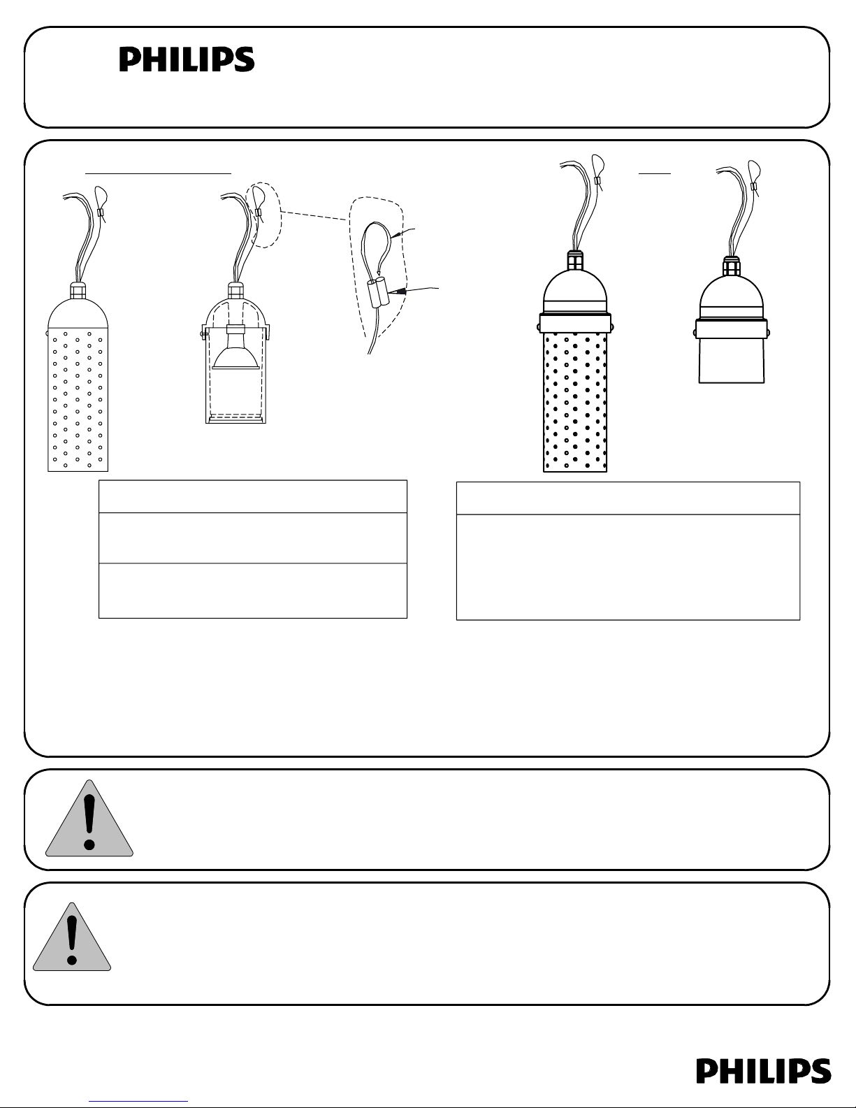
DL1
Possible lamps for incandescent fixtures:
DL1 - 27W #1156 (included)
DRL1 - 35W MR16 Bi-pin
20W MR16 Bi-pin (not supplied)
INSTALLATION
1. Always make sure power is OFF before installing or servicing these fixtures.
2. For incandescent fixtures: Install specified lamp. The screws on the side must be removed to install the lamp.
For LED fixtures: The LED modules are factory installed and are not replaceable. Magnetic low voltage
transformer is required.
3. Use the cable crimp (included) to hang the fixture. Insert end of stainless cable through one side of crimp,
and back through the other side, forming a loop as shown above. Adjust to desired length and crimp tight.
Cut off excess stainless cable.
4. Connect to power using the Low Voltage Connector included with the fixture.
DRL1
Single Contact Bayonet Base
(not supplied) - US only
CABLE
CRIMP
LED Modules (Factory Installed/Not Replaceable)
DL1DC2/DRL1DC2 - 3.7W Cool White
DL1DW2/DRL1DW2 - 3.7W Warm White
DL1DC3/DRL1DC3 - 6.4W Cool White
DL1DW3/DRL1DW3 - 6.4W Warm White
DL1D
LED
DRL1D
This fixture is intended for installation in accordance with the National Electrical Code and local code
specifications. Failure to adhere to these codes and instructions may result in serious injury and/or damage
to the ballast and void the warranty. These instructions do not purport to cover all details or variations in
equipment, nor to provide for every possible contingency related to installation, operation, maintenance,
or mounting situation. Should specific problems occur that are not addressed by these instructions, contact
your Sales Representative or distributor for assistance. Retain these instructions for future reference.
INSTRUCTIONS PERTAINING TO A RISK OF FIRE OR INJURY TO PERSONS-IMPORTANT SAFETY INSTRUCTIONS
Lighted lamp is HOT! WARNING- To reduce the risk of FIRE OR INJURY TO PERSONS: Turn off/unplug and
allow to cool before replacing lamp. Lamp gets HOT quickly! Contact only switch/plug when turning on.
Do not touch hot lens, guard, or enclosure (see diagram/picture). Keep lamp away from materials that
may burn. Do not touch the lamp at any time. Use a soft cloth. Oil from skin may damage lamp. Do not
operate the luminaire fitting with a missing or damaged shield. SAVE THESE INSTRUCTIONS.
Xenon lamps do not require additional shielding.
32000968, revision E
page 1 of 2
LOW VOLTAGE CABLE CONNECTOR INSTRUCTIONS
Low voltage cable connector to be used with 10 or 12 gauge supply cable and 18 gauge fixture cable. Philips
recommends using SPT-3 water resistant (marked "WA", "W" or similar marking) supply cable such as our SCW50010/BSCW500-10 or our SCW100-12/BSCW100-12. Philips also recommends ordering the entire system, which includes the
power console (maximum 25 Amps, 15 Volts per circuit), fixture(s) (low voltage cable connector included) and supply
cable to ensure proper installation and operation.
When using our supply cable, it can be laid on top of the ground, placed under "ground cover" (that is, shallow burial less
than 6 inches or 15.2 cm deep), or directly buried in accordance with the NEC. If not using our cable, per UL 1838-Standard
for Low Voltage Landscape Lighting Systems, the secondary cable must be SPT-3 or suitable for wet locations, sunlight
resistant and direct burial per UL 493 and sized per UL 1838, and it must be buried less than 6 inches (15.2 cm).
Philips recommends a minimum depth of 4 inches when burying in the lawn to prevent damage from aerators or other lawn
plugging equipment.
The 18 gauge fixture cable (provided with fixture) must be protected by routing in close proximity to the fixture or secured
to a building structure such as a house or deck. The fixture cable must be cut off so that it is connected to the low voltage
cable connector within 6 inches (15.2 cm) of the fixture or the building structure. When making an underground connection
to the 10 or 12 gauge supply cable (not provided), the fixture cable must not be buried more than 6 inches (15.2 cm).
WARNING-Mount the luminaire in or on non-combustible mounting surfaces only.
WARNING-Risk of Electric Shock. Install all luminaires 10 feet (3.05m) or more from a pool, spa, or fountain.
Connect the supply cable to the terminals on the power console (transformer) and turn ON.
1.
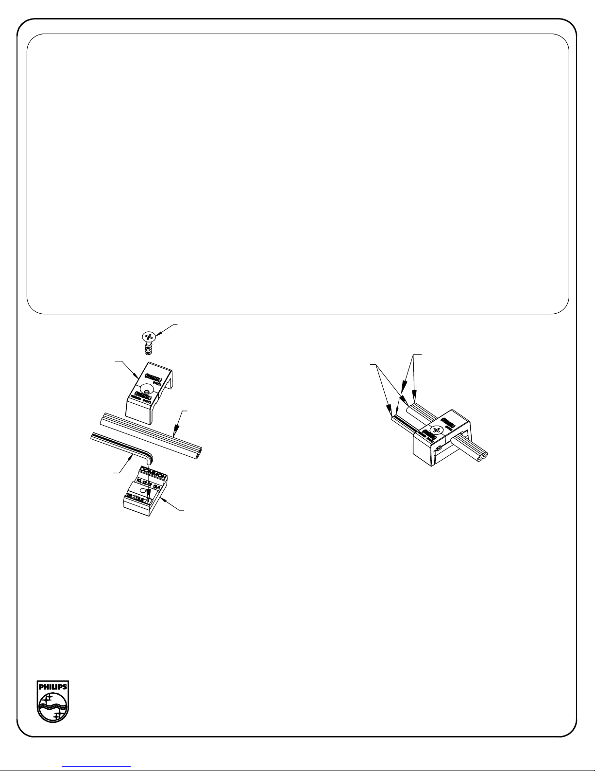
Disassemble the connector by removing the Phillips head screw.
2.
Inspect the connector to ensure the prongs are straight. If the prongs are bent, straighten with pliers.
3.
Insert the end of the fixture cable into the square opening in the connector body. Bend wire over so that wire is laying in
4.
the recess marked '18 GA'. This will help hold the wire in place while performing steps 5 and 6. Only 2-wire cable is to be
used and the common (smooth) wire and hot (ribbed) wires must be oriented as shown.
Press the supply cable into the recess marked '10,12/2 GA' on the connector body. Again the common (smooth) wires
5.
and the hot (ribbed) wires must be oriented as shown.
Press the connector cover onto the connector body, making sure the screw holes line up with each other.
6.
Assemble the connector by tightening the Phillips head screw. NOTE: Make sure the metal prongs in the connector
7.
pierce all 4 wires; the fixture will light as the prongs pierce the wires.
screw
cover
fixture cable
common (smooth)
hot (ribbed)
supply cable
body
32000968, revision E
page 2 of 2
 Loading...