

Philips M8031B, M8033C, 865299 Service Manual

Philips M8031B, M8033C & 865299
Part Number 4535 641 52251
Service Guide
Philips M8031B, M8033C & 865299
15”, 17” & 19” LCD Color Displays
Patient Monitoring
*453564152251*


1Table of Contents
1 Introduction 3
Who Should Use This Guide 3
Responsibility of the Manufacturer 3
Warnings and Cautions 4
2 Installation (M8031B & M8033C) 5
Dimensions 5
M8031B 15” Display 5
Power Supply 6
M8033C 17” Display 7
Installation 8
Positioning 8
Mounting Instructions 10
Desk Stand (Optional) 10
Connections M8031B 11
Connections M8033C 13
Connecting AC Power (M8031B) 14
Connecting AC Power (M8033C) 15
Connecting Digital Video (DVI) 16
Connecting Analog Video (XGA) 17
Connecting the Touch Screen 18
3 Installation (865299) 19
Dimensions 19
865299 19” Display 20
Power Supply 22
Installation 22
Positioning 22
Mounting Instructions 23
Rear Mounting Using the VESA Interface 24
Connections 865299 24
Touch Interface Connection 25
Connecting the Video Cable 25
Connecting the Serial and USB Touchscreen Cable 25
Connecting the Speaker Cable 26
Connecting the Power Cable 26
4 Testing and Maintenance 29
Introduction 29
1

Terminology and Definitions 29
Tests Recommended When Performing... 30
Installation 30
Repair 30
Testing Sequence 31
Visual Inspection 31
Before Each Use 31
After Each Service, Maintenance or Repair Event 31
Power On Test 31
Safety Testing 32
Warnings, Cautions and Safety Precautions 32
Safety Test Procedures 33
Hints for Correct Performance of Safety Tests 33
Guideline for Performance of Safety Tests 34
S(1): Protective Earth Resistance Test 35
S(2): Equipment Leakage Current Test - Normal Condition 36
S(3): Equipment Leakage Current Test - Single Fault Condition 37
Reporting of Test Results 37
Carrying Out and Reporting Tests 39
Tes t R ep or t 3 9
Evaluation 40
Evaluation of Test Results 40
Explanation of Symbols Used 41
After Installation, Testing or Repair 41
5 Troubleshooting 43
Signal missing 43
Cable disconnected 44
6 Repair and Disassembly 45
Backlight Replacement (M8031B & M8033C only) 45
Tools required 45
M8031B Backlight Replacement 46
Removing the LCD Panel from the Display Unit 46
Replacing the Backlights 54
M8033C Backlight Replacement 59
7 Part Numbers 65
2

This Service Guide contains technical details for the M8031B 15”, the M8033C 17” and the 865299
19” LCD Color Display.
This guide provides a technical foundation to support effective troubleshooting and repair. It is not a
comprehensive, in-depth explanation of the product architecture or technical implementation. It offers
enough information on the functions and operations of the display so that engineers who repair them
are better able to understand how they work.
Who Should Use This Guide
This guide is for biomedical engineers or technicians responsible for troubleshooting, repairing, and
maintaining Philips’ patient monitoring systems. A good understanding of the English language is a
requirement.
1
1Introduction
Responsibility of the Manufacturer
Philips only considers itself responsible for any effects on safety, EMC, reliability and performance of
the equipment if:
• assembly operations, extensions, re-adjustments, modifications or repairs are carried out by persons
authorized by Philips, and
• the electrical installation of the relevant room complies with national standards, and
• the instrument is used in accordance with the instructions for use.
To ensure safety and EMC, use only those Philips parts and accessories specified for use with the
monitor. If non-Philips parts are used, Philips is not liable for any damage that these parts may cause to
the equipment.
This document contains proprietary information which is protected by copyright. All Rights Reserved.
Reproduction, adaptation, or translation without prior written permission is prohibited, except as
allowed under the copyright laws.
Philips Medizin Systeme Böblingen GmbH
Hewlett-Packard Str. 2
71034 Böblingen, Germany
The information contained in this document is subject to change without notice.
Philips makes no warranty of any kind with regard to this material, including, but not limited to, the
implied warranties or merchantability and fitness for a particular purpose.
3

1 Introduction Warnings and Cautions
Philips shall not be liable for errors contained herein or for incidental or consequential damages in
connection with the furnishing, performance, or use of this material.
Warnings and Cautions
In this guide:
•A warning alerts you to a potential serious outcome, adverse event or safety hazard. Failure to
observe a warning may result in death or serious injury to the user or patient.
•A caution alerts you where special care is necessary for the safe and effective use of the product.
Failure to observe a caution may result in minor or moderate personal injury or damage to the
product or other property, and possibly in a remote risk of more serious injury.
4
2Installation (M8031B & M8033C)
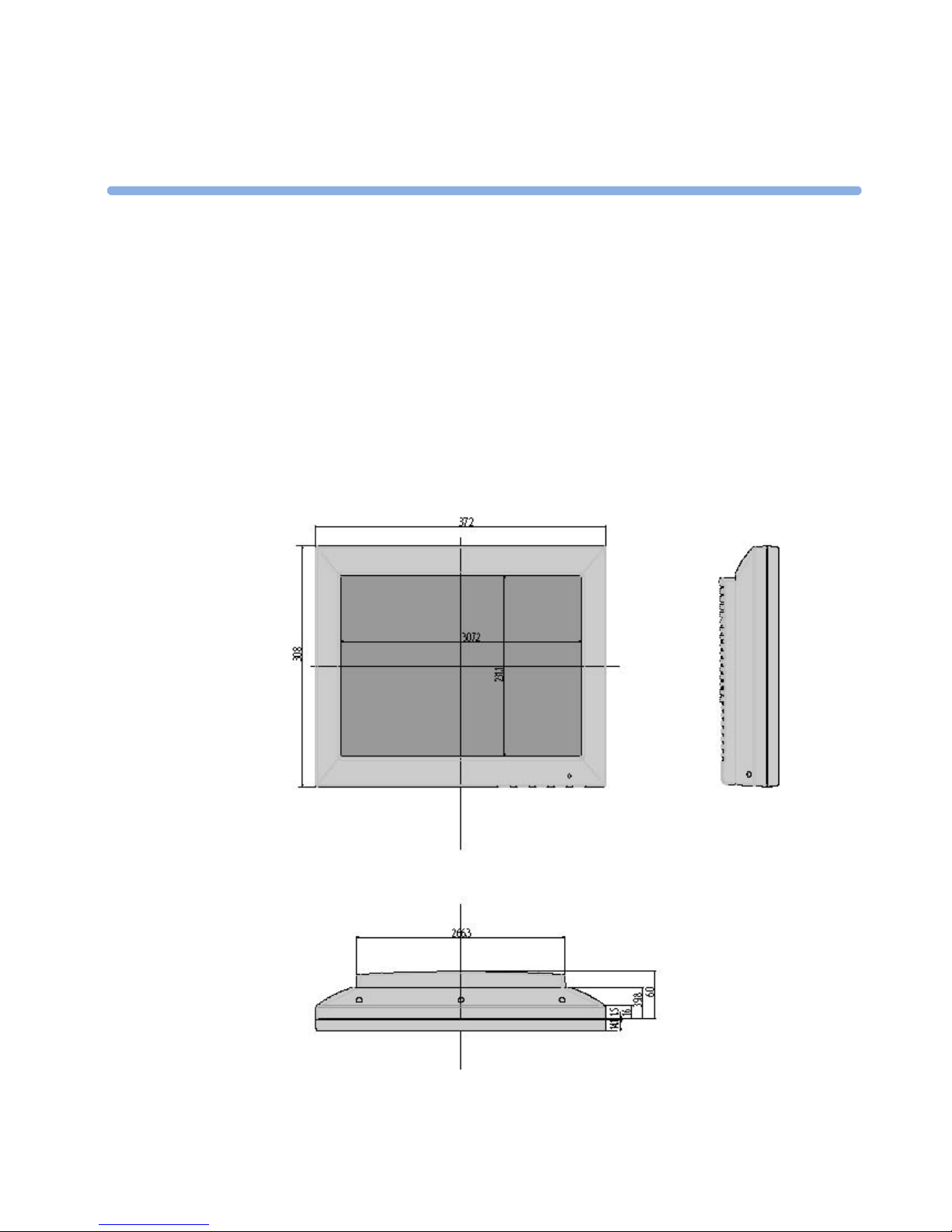
Dimensions
The following graphics show the dimensions of the display and the power supply. Please allow for a
sufficient amount of space for installation of the display.
M8031B 15” Display
Dimensions: in mm; Weight: approx. 5 kg without desk stand
2
5
2 Installation (M8031B & M8033C) Dimensions
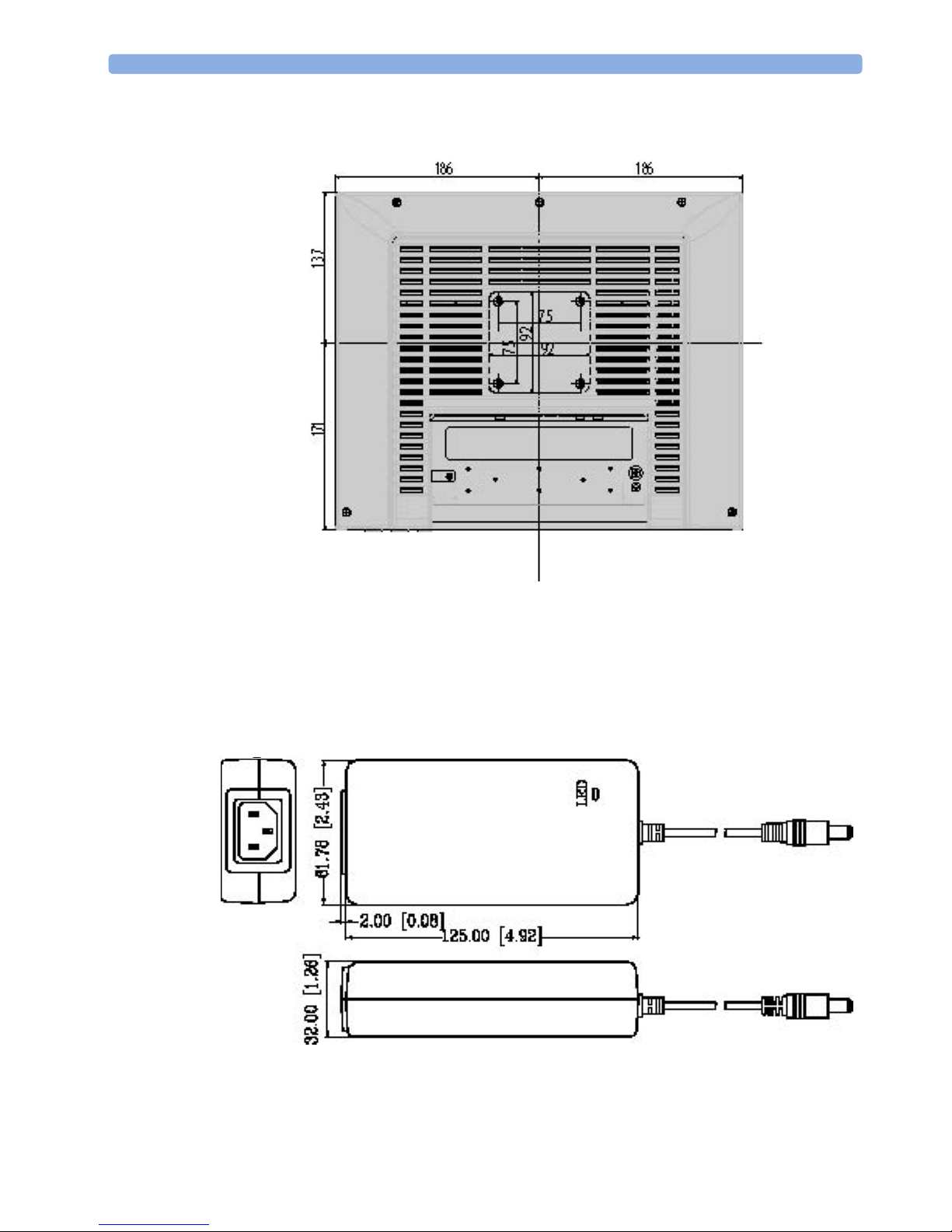
Power Supply
Dimensions: mm (inches)
Weight: 373g (13,2 Oz).
6
Dimensions 2 Installation (M8031B & M8033C)
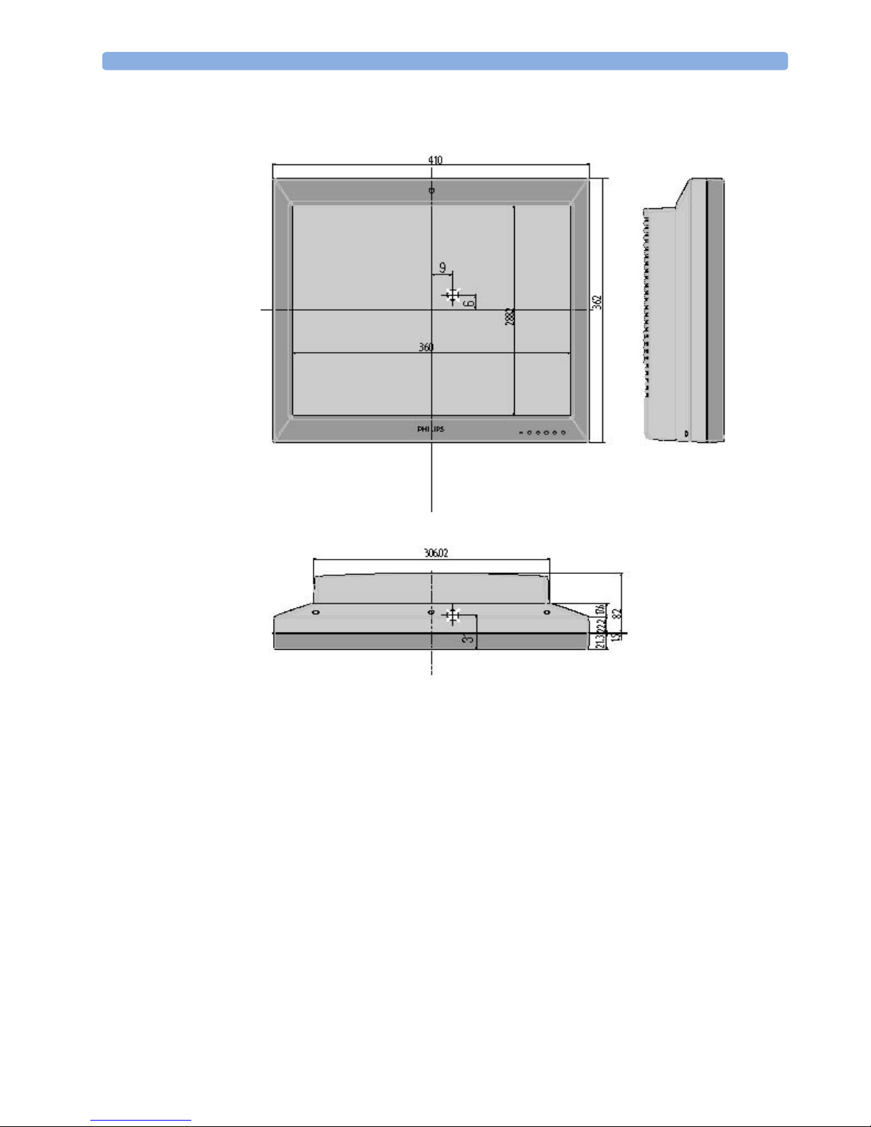
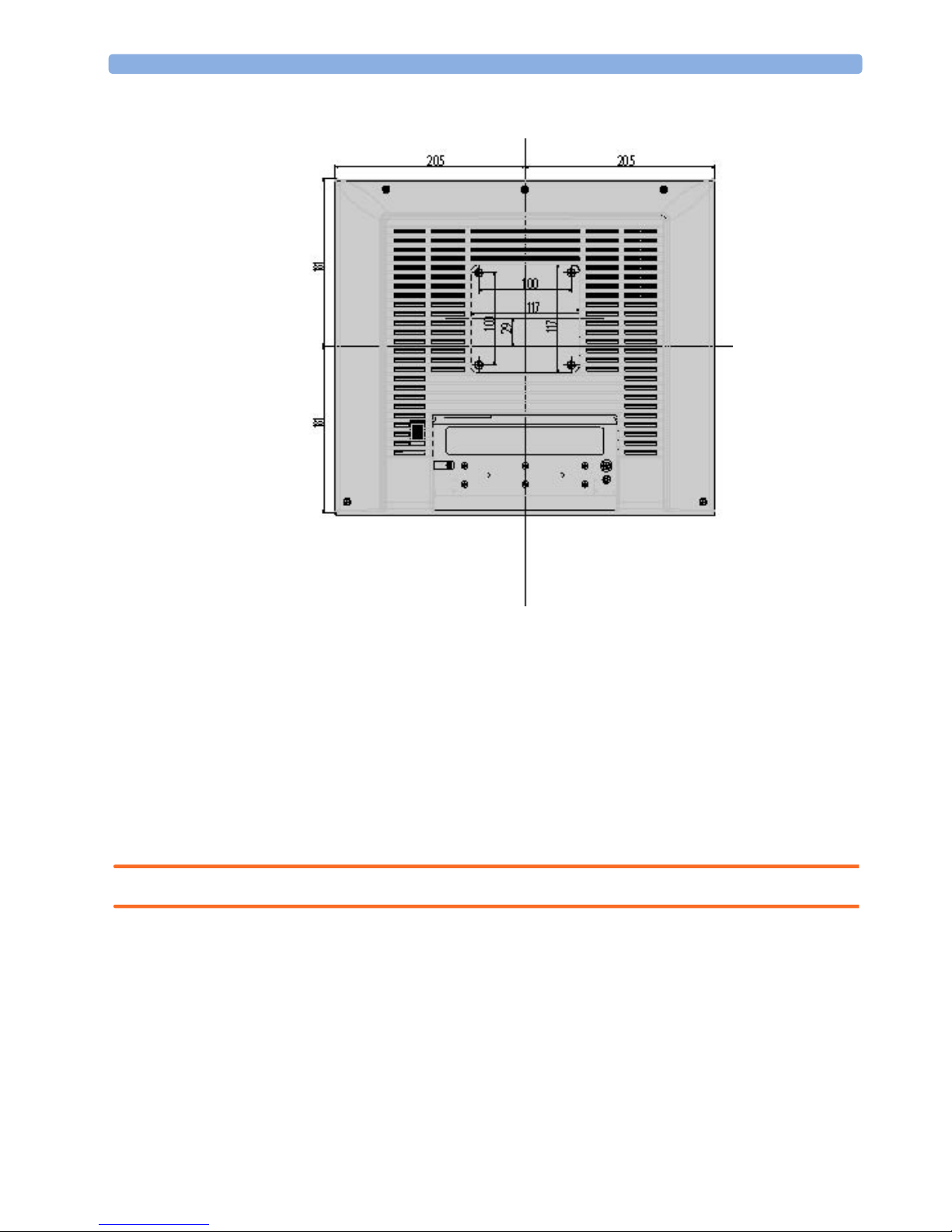
M8033C 17” Display
Dimensions: in mm; Weight: approx. 7kg without desk stand
7
2 Installation (M8031B & M8033C) Installation
Installation
We recommend that you install the display near a grounded wall outlet in an area that is relatively free
of glare from sunlight or other sources of bright light. Before unpacking the display, prepare the
mounting or desk stand which should be used with the display.
NOTE Before installing this display, please refer to the user’s guides of your host device in order to confirm
compatibility.
Positioning
WARNING When positioning this equipment, ensure that the mains plug and socket are easily accessible.
While unpacking the display, inspect it and other package contents for shipping damage. If physical
damage is evident or if the display does not meet the specified operational requirements of the patient
safety checks or the extended self check when the equipment is received, notify the carrier and the
nearest Philips Sales/Support Office immediately. Philips will arrange for immediate repair or
replacement of the instrument without waiting for the claim settlement by the carrier. Keep all packing
material in case you need to ship, store or return the display.
8

Installation 2 Installation (M8031B & M8033C)
After unpacking the display, make sure the following items are included:
•display
•AC Power Supply
• Mains cord set 1,8-meter
•Video Signal cable
• Touch screen cable
• User and Service Documentation
9
2 Installation (M8031B & M8033C) Mounting Instructions
Mounting Instructions
WARNING It is the customer’s responsibility to have the attachment of the mounting hardware to the ceiling, wall,
or mounting rail and the construction of the ceiling, wall or mounting rail evaluated for structural
integrity and compliance with all local, state and any other required codes by a registered, professional,
structural and/or mechanical engineer. Ensure that this commitment has been met before assembling
mounts. Incorrect mounting and use of inappropriate mounting material may lead to injury. It is the
customer’s responsibility to ensure that the mounting procedures have been performed correctly and
the appropriate mounting devices have been used.
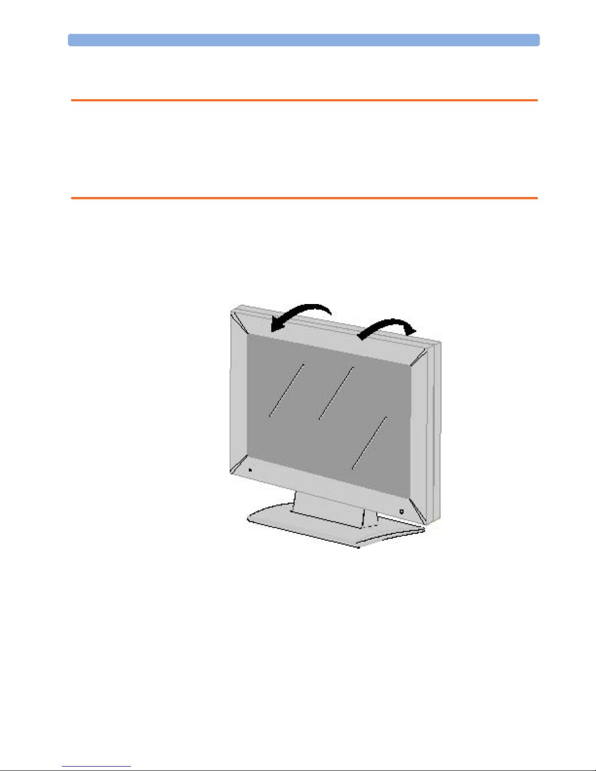
Desk Stand (Optional)
With the desk stand (Part No.: M8031-04701, 12NC: 451261001901) you can tilt the display to the
most comfortable viewing angle.
5°
15°
For other mounting options please refer to the Philips IntelliVue Mounting Solutions Website.
10
Connections M8031B 2 Installation (M8031B & M8033C)
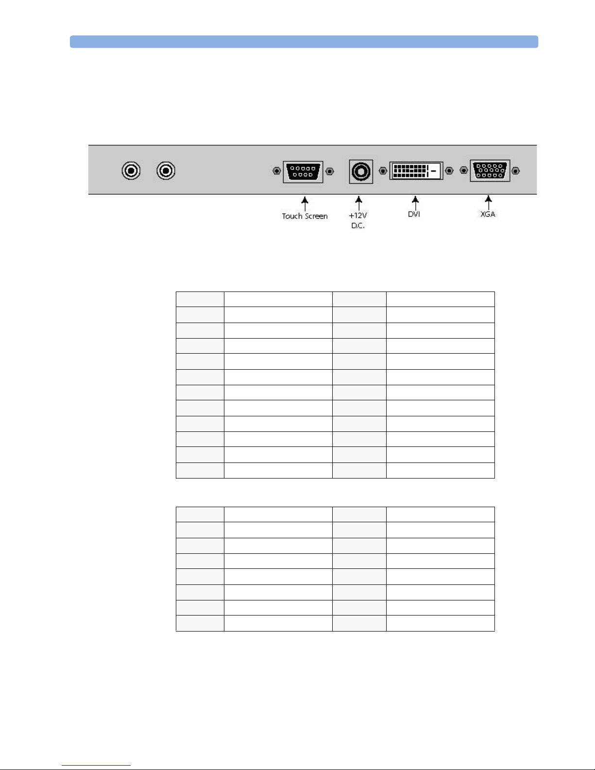
Connections M8031B
The graphic below shows the display connectors. These are located on the back of the display below
the mounting plate and are accessible from the bottom.
• +12V D.C. Connection (Power jack)
• DVI INPUT (Microcross™ DVI-D female connector)
Pin 1
Pin 2
Pin 3
Pin 4
Pin 5
Pin 6
Pin 7
Pin 8
Pin 9
Pin 10
Pin 11
Pin 12
D2_RX - (T.M.D.S.)
D2_RX + (T.M.D.S.)
GND (Data 2 shield)
N.C.
N.C.
SCL (For DDC)
SDA (For DDC)
N.C.
D1_RX - (T.M.D.S.)
D1_RX + (T.M.D.S.)
GND (Data 1 shield)
N.C.
Pin 13 N.C.
Pin 14 +5V Power
Pin 15 GND
Pin 16 Hot Plug Detect
Pin 17 D0_RX - (T.M.D.S.)
Pin 18 D0_RX + (T.M.D.S.)
Pin 19 GND (Data 0 shield)
Pin 20 N.C.
Pin 21 N.C.
Pin 22 GND (Clock shield)
Pin 23 CK_RX + (T.M.D.S.)
Pin 24 CK_RX - (T.M.D.S.)
• VIDEO INPUT XGA Connection (DSUB15 female connector)
Pin 1
Pin 2
Pin 3
Pin 4
Pin 5
Pin 6
Pin 7
Pin 8
R-in
G-in
B-in
N.C.
GND
GND
GND
GND
Pin 9 N.C.
Pin 10 GND
Pin 11 GND
Pin 12 SDA-Vesa
Pin 13 H.S.-in
Pin 14 V.S.-in
Pin 15 SCL-Vesa
11

2 Installation (M8031B & M8033C) Connections M8031B
• RS 232 Connection (DSUB9 female connector))
Pin 1
Pin 2
Pin 3
Pin 4
Pin 5
N.C
TX
RX
N.C.
GND
Pin 6 N.C.
Pin 7 N.C
Pin 8 N.C
Pin 9 N.C.
12
Connections M8033C 2 Installation (M8031B & M8033C)
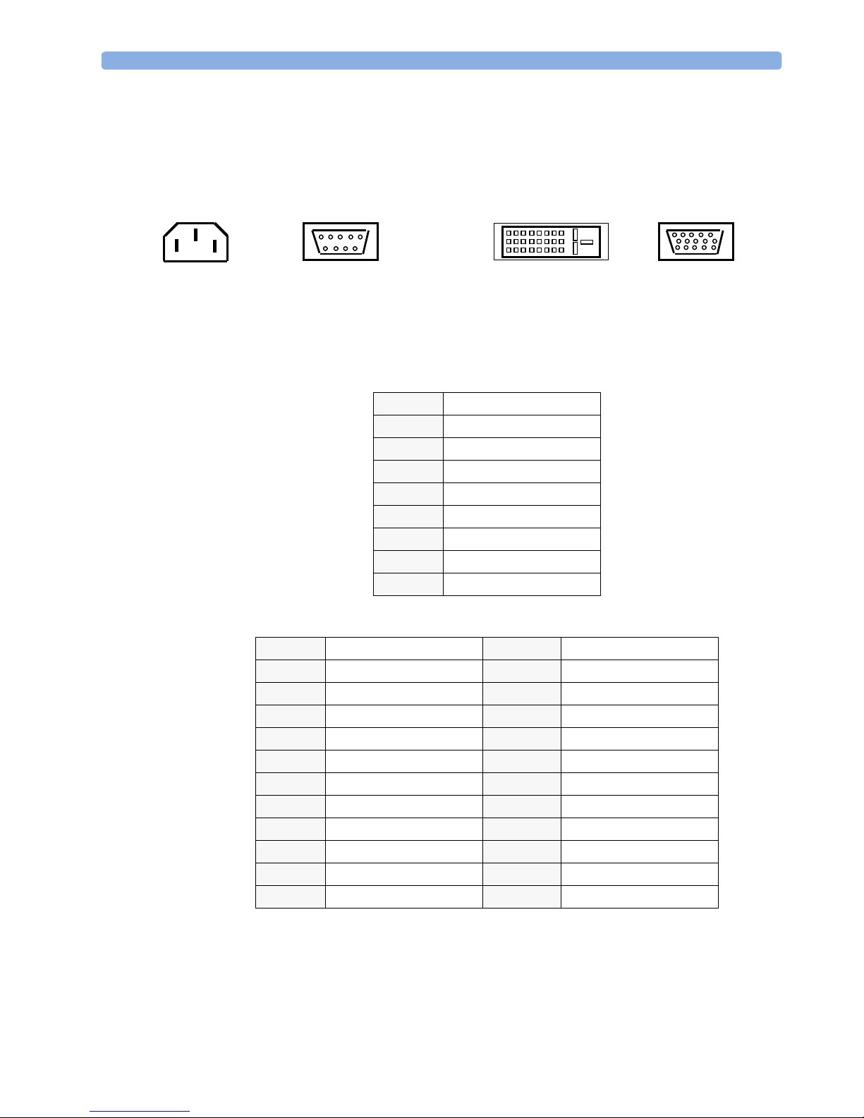
Connections M8033C
The graphic below shows the display connectors. These are located on the back of the display below
the mounting plate and are accessible from the bottom.
Power Touch Screen
• CEE 22-6A IEC320 male pin receptacle connector
• RS232 DSUB-9 connector pinout
Pin 1
Pin 2
Pin 3
Pin 4
Pin 5
Pin 6
Pin 7
Pin 8
Pin 9
• DVI 24-pin connector Digital Video Input
Pin 1
Pin 2
Pin 3
Pin 4
Pin 5
Pin 6
Pin 7
Pin 8
Pin 9
Pin 10
Pin 11
Pin 12
RX2RX2+
GND
N.C.
N.C.
Vesa_SCL
Vesa_SDA
N.C.
RX1RX1+
GND
N.C.
Tx-Data
Rx-Data
Ground
-
-
-
-
DVI
Pin 13 N.C.
Pin 14 +5V
Pin 15 GND
Pin 16 sense
Pin 17 RX0Pin 18 RX0+
Pin 19 GND
Pin 20 N.C.
Pin 21 N.C.
Pin 22 GND
Pin 23 RXC+ (clock)
Pin 24 RXC-
SXGA
13
2 Installation (M8031B & M8033C) Connections M8033C
• Input DSUB-15 connector (VGA type) Analog RGB
Pin 1
Pin 2
Pin 3
Pin 4
Pin 5
Pin 6
Pin 7
Pin 8
RED
GREEN
BLUE
N.C.
GND
GND
GND
GND
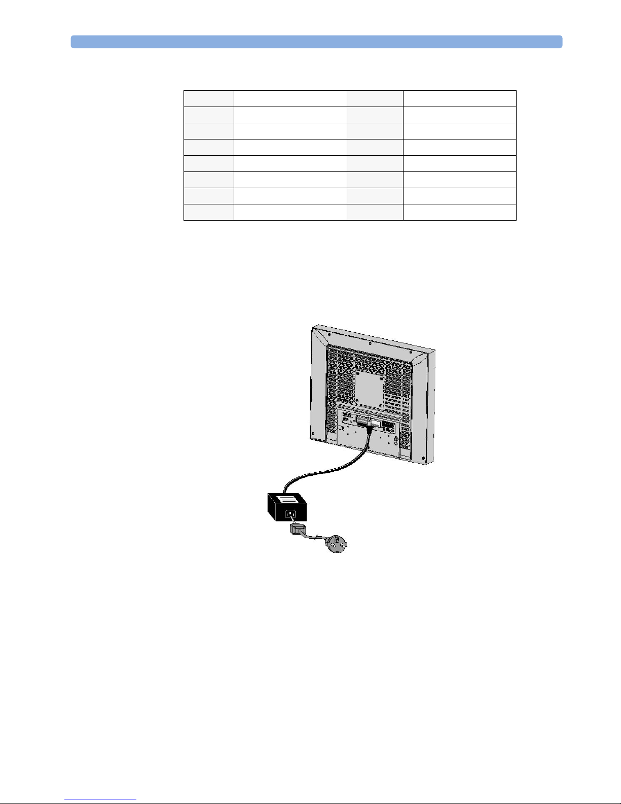
Connecting AC Power (M8031B)
Plug the receptacle of the AC power cord into the AC power adapter, then plug the power connector of
the adapter into the power port on the display.
This power port is located at the back of the display.
Pin 9 N.C.
Pin 10 GND
Pin 11 GND
Pin 12 Vesa_SDA
Pin 13 Hsync
Pin 14 Vsync
Pin 15 Vesa_SCL
14
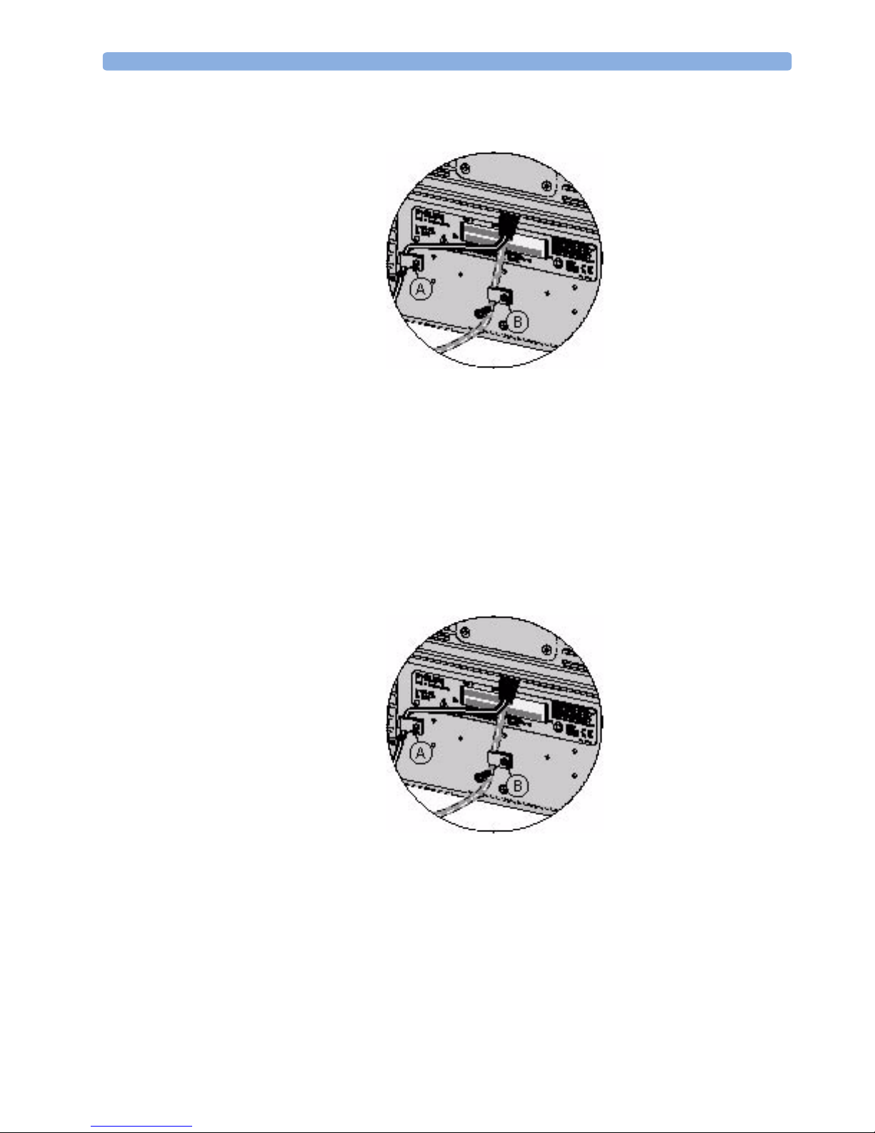
Connections M8033C 2 Installation (M8031B & M8033C)
The power connector should be fixed to the cabinet with the proper cable clamp and screw.
Insert the plug end of the power cord into a grounded wall outlet.
If needed add the Power Supply Holder M8031-64001 (451261001931) to your installation.
Connecting AC Power (M8033C)
Plug the receptacle of the AC power cord into the power port on the display. This power port is located
at the back of the display.
NOTE The M8033C Display has an integrated power supply.
The power connector should be fixed to the cabinet with the proper cable clamp and screw.
Insert the plug end of the power cord into a grounded wall outlet.
15
2 Installation (M8031B & M8033C) Connections M8033C
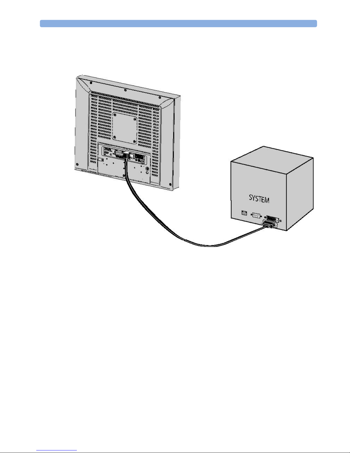
Connecting Digital Video (DVI)
With both system and display powered off, connect the digital video cable from the display to the
system’s DVI video port.
Make sure the video cable connector is securely connected to the system video port.
Switch the display on first, and then switch on the system.
16
Connections M8033C 2 Installation (M8031B & M8033C)
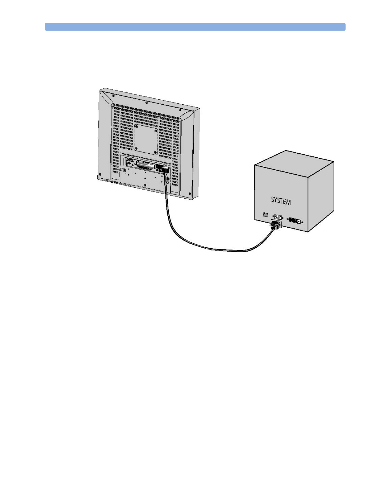
Connecting Analog Video (XGA)
With both system and display powered off, connect the analog video cable from the display to the
system’s D-SUB video port.
Make sure the video cable connector is securely connected to the system video port.
Switch the display on first, and then switch on the system.
17

2 Installation (M8031B & M8033C) Connections M8033C
Connecting the Touch Screen
Connect the display’s RS-232 serial port to the system’s serial port using the appropriate cable.
18

Dimensions
The following graphics show the dimensions of the display and the power supply. Please allow for a
sufficient amount of space for installation of the display.
3
3Installation (865299)
19
 Loading...