How it Works
Log In / Sign Up
Buy Points
How it Works
FAQ
Contact Us
Questions and Suggestions
Users
Philips
Loading...
M
M204878
M2052/00
2
M2052/01
M2052/11
M206878
M2132/00
M2132/11
M2152/00
2
M2152/11
M2182/00
2
M2192
M2192-05
M2239CLE1T
M2244EL1
M25/00
10
M2505
2
M253515
M253578
M2537-15
M253778
M253815
M253878
M2540
M2540A
M254215
M254278
M259378
M259678
M2600
M2600A
M2636B TeleMon B
M267378
M271415
M271478
M2715-15
M271578
M2720
M272578
M2922
M2922A
M2922A FM-2
10
M2925A
M2926A
M2BT
M2BTBK
M2BTBK/27
M2L/27
M3
2
M3000A
M3001A
M3046
M3046A
2
M310
2
M315
2
M3151SB/FR
M330
6
M3301
2
M3301PW
M3301SB
M3301W
2
M3301W-51
M335
4
M3351W-05
M341578
M341678
M341778
M342078
M342278
M3451B/FR
M350
M3500B
M3501W
M3501W/34
M351
M3535A
4
M3535A HeartStart MRx
M3536A
4
M3536A HeartStart MRx
M3860A
M3861A
M3921A
M3922A
M3923A
M3924A
M3926A
M3927A
M3928A
M3929A
M4
2
M4735A
M5066A
3
M5068A
2
M5085A
M550
10
M5501
M5501BW
M5501WA
M5501WG
4
M5501WR
2
M5529A
Loading...
Loading...
Nothing found
M3046
Service Manual
243 pgs
5.47 Mb
0
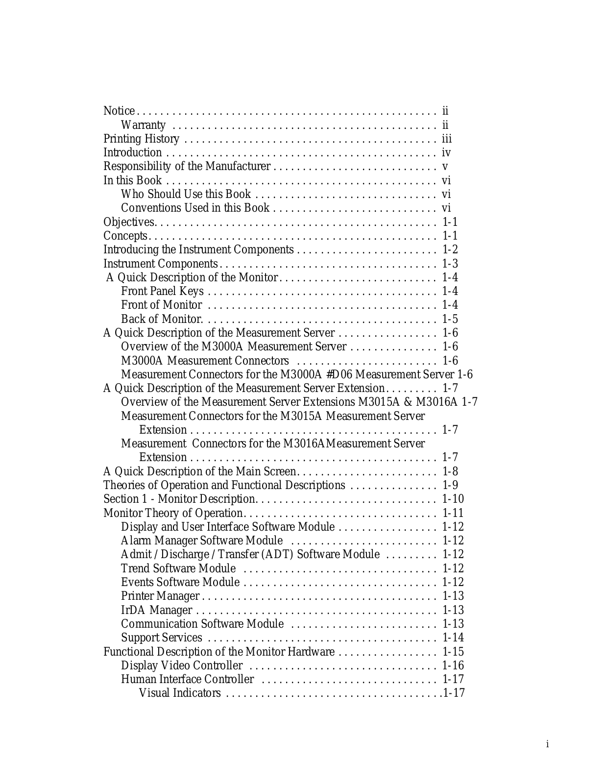
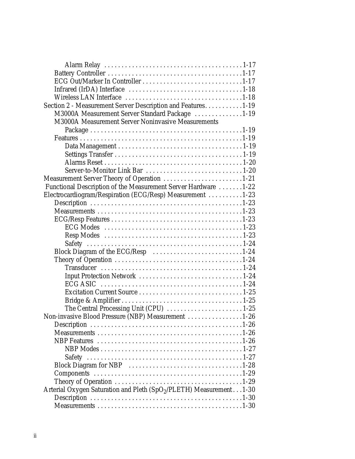
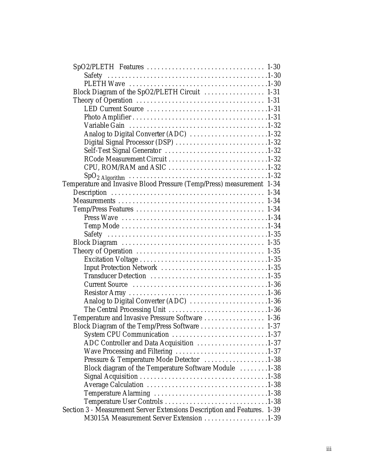
Table of contents
Loading...
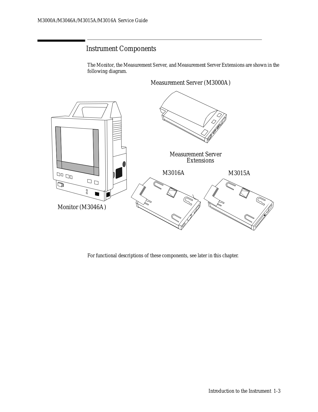
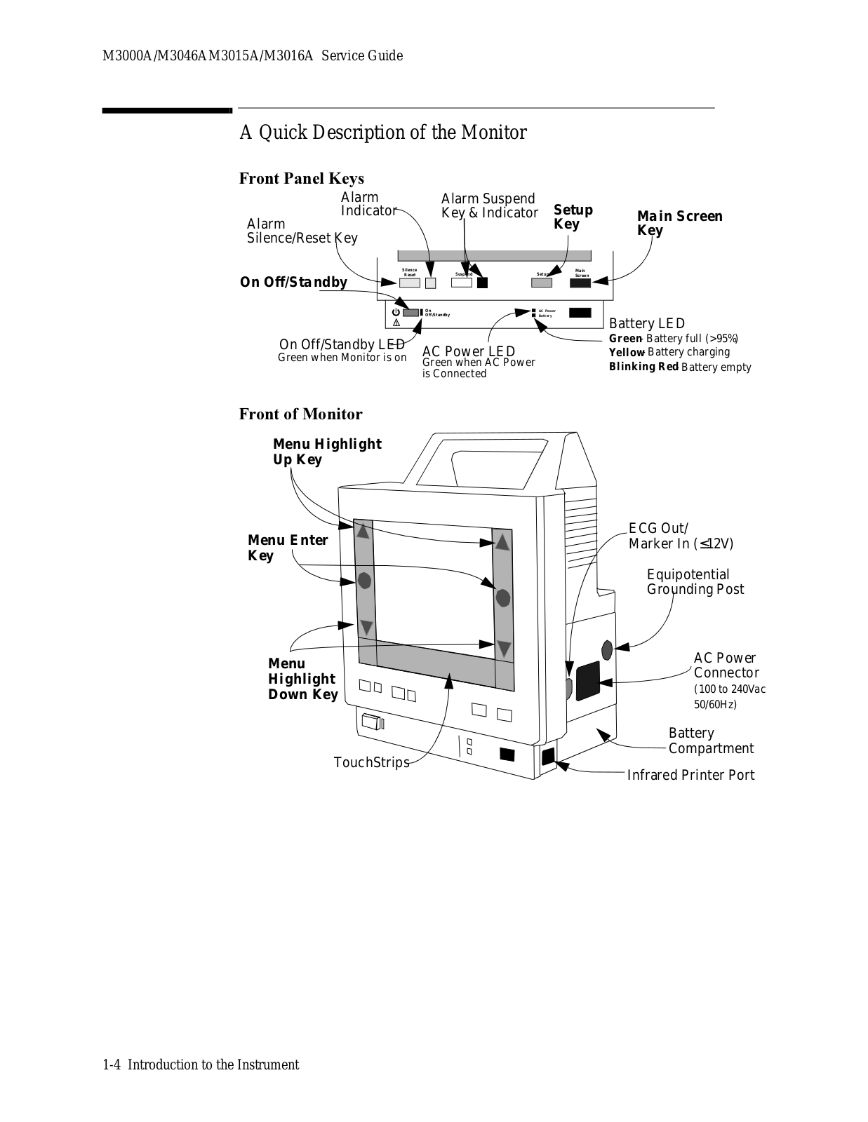
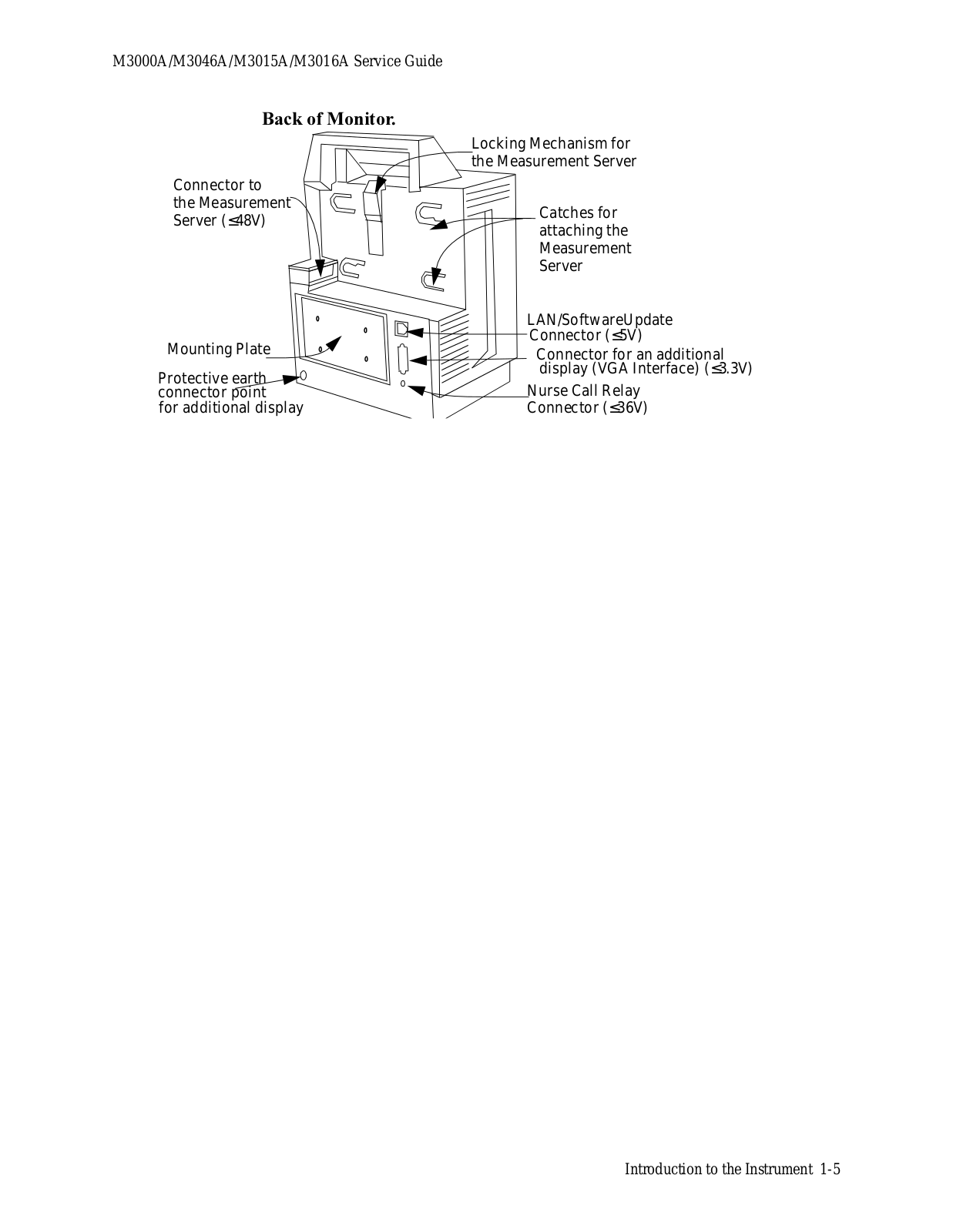
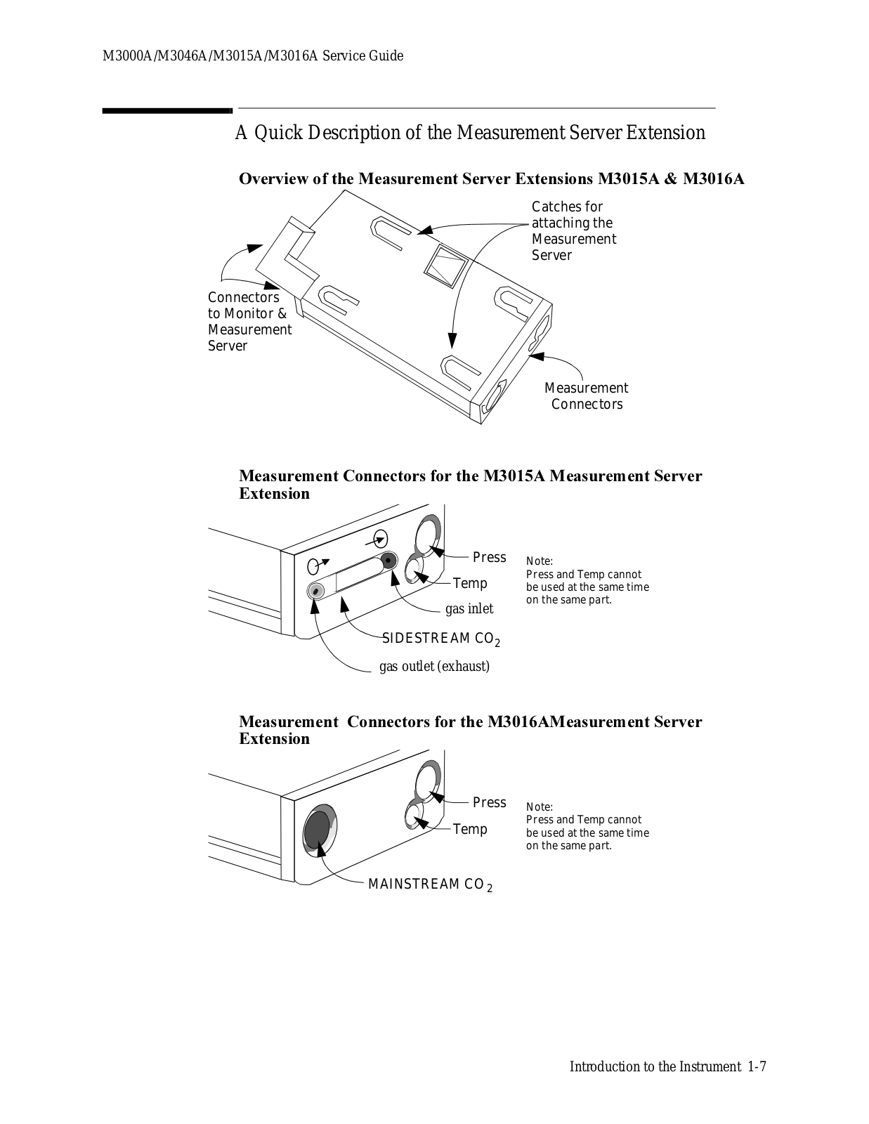
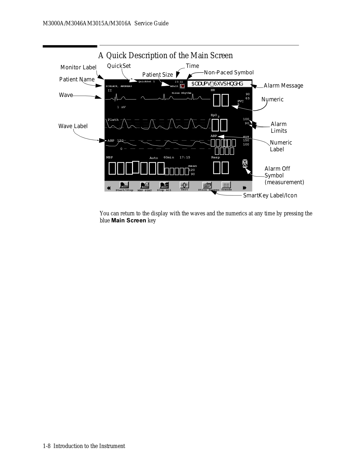
Philips M3046 Service Manual
...
Philips Service Manual
Download
Specifications and Main Features
Frequently Asked Questions
User Manual
Download
Loading...
+
213
hidden pages
Unhide
You need points to download manuals.
1 point = 1 manual.
You can buy points or you can get point for every manual you upload.
Buy points
Upload your manuals
 Loading...