

Page 1

Philips M1032A VueLink
External Device
Service Booklet
PHI
Part Number M1032-9000Y
4512 610 18581
Published in October 2006
Edition 22
Y.00.00
Page 2

Notice
Important
Philips makes no warranty of any kind with regard to this material, including, but
not limited to, the implied warranties of merchantability and fitness for a particular
purpose. Philips shall not be liable for errors contained herein or for incidental or
consequential damages in connection with the furnishing, performance or use of
this material.
This document contains proprietary information that is protected by copyright. All
rights are reserved. No part of this document may be photocopied, reproduced or
translated to another language without prior written consent of Philips Medical
Systems. The information contained in this document is subject to change without
notice. Philips assumes no responsibility for the use or reliability of its software on
equipment that is not furnished by Philips.
United States federal law restricts these devices to sale by or on the order of a
physician.
2
Page 3

Intended Use
Description The Philips M1032A VueLink module is a plug-in module for use with a Philips
IntelliVue, V24 or V26 Patient Monitor or a Philips CMS Patient Monitoring
System.
The Philips M1032A VueLink module is powered via the patient monitor.
Purpose The Philips M1032A VueLink module transmits information from a connected
external device to a Philips IntelliVue, V24 or V26 Patient Monitor or a Philips CMS
Patient Monitoring System. The Philips M1032A VueLink module is not a
therapeutic device.
Environ-
ment
The Philips M1032A VueLink module is intended to be used in a clinical
environment by trained healthcare professionals. It is not intended for home use.
3
Page 4

Indications for Use
Condition The use of a Philips M1032A VueLink module is generally indicated when the
clinician decides there is a need to include the physiological and device parameters
and waves and alarms generated by external devices into the Philips IntelliVue, V24
or V26 Patient Monitor or a Philips CMS Patient Monitoring System.
Part of Body
or Type of
Tissue with
Which the
Device Inter-
acts
Frequency
of Use
Physiologi-
cal Purpose
Patient Pop-
ulation
Prescrip-
tion Versus
Over-the-
Counter
The Philips M1032A VueLink module does not contact the body or tissue of the
patient. Signals are obtained from external devices.
The Philips M1032A VueLink module is indicated for use when prescribed by a
clinician.
The Philips M1032A VueLink module is indicated when the purpose is to gain
information for treatment, to assess adequacy of treatment, or to rule out causes
of symptoms. The Philips M1032A VueLink module is well suited for patient
monitoring.
Please refer to the documentation describing the external device.
The Philips M1032A VueLink module is a prescription device.
4
Page 5

Warnings, Cautions and Notes
In this guide:
Warning
•A
warning
alerts you to a potential serious outcome, adverse event or
safety hazard.
Failure to observe a warning may result in death or serious injury to the
user or patient.
Caution A caution alerts you where special care is necessary for the safe and effective
use of the product.
Failure to observe a caution may result in minor or moderate personal injury
or damage to the product or other property, and possibly in a remote risk of
more serious injury.
Note A note gives special instructions to highlight an operating procedure or practice.
Notes may precede or follow the applicable text.
5
Page 6

Responsibility of the Manufacturer
Philips Medical Systems only considers itself responsible for any effects on safety,
reliability and performance of the equipment if:
• assembly operations, extensions, re-adjustments, modifications or repairs are
carried out by persons authorized by Philips, and
• the electrical installation of the relevant room complies with national
standards, and
• the Philips M1032A VueLink module is used in accordance with the
instructions for use contained in this document, and in the relevant chapter
of the user documentation for the patient monitor into which the module is
plugged (Philips IntelliVue, V24 or V26 Patient Monitor or a Philips CMS
Patient Monitoring System).
Warning
• Failure on the part of the responsible individual hospital or institution
employing the this equipment to implement a satisfactory maintenance
schedule may cause undue equipment failure and possible health
hazards.
The maintenance schedule is defined in the Testing and Maintenance
chapter of the IntelliVue Patient Monitor Service Guide, the Philips CMS
Patient Monitoring System Service Guide, or the Philips V24/V26
Component Monitoring System Service Guide, corresponding to your
monitor.
Note Not all the device drivers are available in all countries.
The Instructions for Use for all drivers are translated into the following languages:
Czech, Danish, Dutch, Estonian, Finnish, French, German, Greek, Hungarian,
Italian, Japanese, Norwegian, Polish, Portuguese, Romanian, Russian, Simplified
Chinese (China), Slovak, Spanish, Swedish, Traditional Chinese (Taiwan), Turkish.
The driver software may not be available in all of these languages. Please refer to the
CMS-PM softserver (
http://pww.softserver.anr.ms.philips.com/navigation.asp,
6
Page 7

subfolder Vuelink, subfolder Additional Information) for a list of the translated
drivers
that are available.
Please also check your local regulatory and business requirements for permission to
sell.
Philips authorized technical personnel are responsible for the setup, configuration
and repair of the VueLink module and all related Philips equipment. The
configuration, setup and repair of external devices furnished by manufacturers other
than Philips Medical Systems must be carried out by local site personnel, or by
representatives of the external device manufacturer.
Philips Medical Systems is not responsible for any problems arising from inaccurate
or erroneous data displayed on the Philips patient monitor that is received from
external devices furnished by manufacturers other than Philips Medical Systems.
Philips Medical Systems makes every effort to ensure that signal names are
maintained between the Philips patient monitor and any interfaced external devices.
However, signal names within the Philips patient monitor also need to remain
consistent. This means that in some cases the wave and numeric labels used on the
Philips monitor may be different from those used on the interfaced external device.
Philips Medical Systems will not be held responsible for any errors in the
configuration of the VueLink module for connection to free-analog devices.
If manufacturers other than Philips Medical Systems make changes to any VueLink
supported device, Philips Medical Systems will try to ensure that interfacing to that
device remains possible. However, Philips Medical Systems reserves the right to
discontinue interfacing to any device.
7
Page 8

Introduction
This Service Guide contains technical details for the connection of external devices
to the VueLink module. It is not a comprehensive, in-depth explanation of the
product architecture or technical implementation.
Who Should
Use This
Guide
How to Use
This Booklet
This guide is for biomedical engineers or technicians responsible for connecting
external devices to Philips patient monitoring systems using the VueLink module.
This booklet provides information on the worldwide external devices that can be
connected to the VueLink module. It should be printed and inserted into Appendix
A of the VueLink Module Handbook, completely replacing the existing worldwide
driver information.
The information contained in this document is subject to change without notice.
Philips Medizin Systeme Böblingen GmbH
Hewlett-Packard Str. 2
71034 Böblingen
Germany
© 2006 Philips Medizin Systeme Böblingen GmbH
All rights are reserved.
Reproduction in whole or in part is prohibited without the prior written consent of
the copyright holder.
8
Page 9

Connecting your Device to VueLink
There are two different ways to connect your Device to VueLink:
• Connection via a Supported Device driver.
This uses one of the following device outputs:
–Analog
– RS-232 Digital
– Analog/Digital combination
• Connection via a Free Analog Device driver.
This only uses device analog outputs.
Supported Device Drivers
Supported Device Drivers are preconfigured in the VueLink module. A dedicated
ready-prepared VueLink cable is available for connecting the external device to the
module. (Please refer to page A-4 for cable part numbers).
Connecting your Device to VueLink
Free Analog Device Drivers
Free Analog Device Drivers must be manually configured into the module at
installation. A Free Analog VueLink cable is available for connecting the Free
Analog external device to the VueLink module. One end of the cable is
unterminated and must be prepared for connection to the external device on-site.
(Please refer to page B-4 for cable option part numbers).
9
Page 10

Connecting your Device to VueLink
10
Page 11

Contents
Connecting your Device to VueLink . . . . . . . . . . . . . . . . . . . . . . . . . . . . . . . 9
Supported Device Information . . . . . . . . . . . . . . . . . . . . . . 15
Driver Part Numbers for Supported Devices . . . . . . . . . . . . . . . . . . . . . . . . 16
VueLink Cable Overview . . . . . . . . . . . . . . . . . . . . . . . . . . . . . . . . . . . . . . . . 17
Auxiliary Devices . . . . . . . . . . . . . . . . . . . . . . . . . . . . . . . . . 23
Abbott Oximetrix 3 - SO2 Monitor . . . . . . . . . . . . . . . . . . . . . . . . . . . . . . . . 23
Critikon Dinamap 1846 / 1846 SX - NBP Monitor . . . . . . . . . . . . . . . . . . . . 25
Danmeter AAI/AEP Monitor. . . . . . . . . . . . . . . . . . . . . . . . . . . . . . . . . . . . . . 27
Nellcor® N-200 - SpO2 Monitor. . . . . . . . . . . . . . . . . . . . . . . . . . . . . . . . . . 29
Nellcor® N-100C - SpO2 Monitor . . . . . . . . . . . . . . . . . . . . . . . . . . . . . . . . 31
Ventilators . . . . . . . . . . . . . . . . . . . . . . . . . . . . . . . . . . . . . . 33
Nellcor Puritan-Bennett 740 / 760 / 840 Ventilators. . . . . . . . . . . . . . . . . . . 33
Puritan-Bennett 7200a / 7200ae Ventilator . . . . . . . . . . . . . . . . . . . . . . . . . . 36
Dräger Babylog 8000 Ventilator . . . . . . . . . . . . . . . . . . . . . . . . . . . . . . . . . . . 38
Dräger Evita Ventilator . . . . . . . . . . . . . . . . . . . . . . . . . . . . . . . . . . . . . . . . . . 40
Dräger Evita 2 Ventilator . . . . . . . . . . . . . . . . . . . . . . . . . . . . . . . . . . . . . . . . 42
Dräger Evita 2 Dura, Dräger Evita 4 & Dräger Evita XL Ventilators . . . . . . 44
Dräger Graphic Screen for Babylog 8000 . . . . . . . . . . . . . . . . . . . . . . . . . . . 46
Dräger Graphic Screen for Savina . . . . . . . . . . . . . . . . . . . . . . . . . . . . . . . . . 48
Dräger Savina . . . . . . . . . . . . . . . . . . . . . . . . . . . . . . . . . . . . . . . . . . . . . . . . . 50
GE Engström Carestation Ventilator . . . . . . . . . . . . . . . . . . . . . . . . . . . . . . . 52
Hamilton Veolar, Veolar FT, and Amadeus Ventilators. . . . . . . . . . . . . . . . . 54
BEAR 1000 Ventilator . . . . . . . . . . . . . . . . . . . . . . . . . . . . . . . . . . . . . . . . . . . 56
Infrasonics® Infant Star / ISV Ventilator . . . . . . . . . . . . . . . . . . . . . . . . . . . . . 58
Siemens SCM 990 Ventilator . . . . . . . . . . . . . . . . . . . . . . . . . . . . . . . . . . . . . 61
Siemens 900 C/D/E Ventilator . . . . . . . . . . . . . . . . . . . . . . . . . . . . . . . . . . . . 64
Maquet Servo 300/300A Ventilator . . . . . . . . . . . . . . . . . . . . . . . . . . . . . . . . 66
Maquet SERVO-i Ventilator . . . . . . . . . . . . . . . . . . . . . . . . . . . . . . . . . . . . . . 68
Maquet SERVO-s Ventilator . . . . . . . . . . . . . . . . . . . . . . . . . . . . . . . . . . . . . . 70
Gas Analyzers . . . . . . . . . . . . . . . . . . . . . . . . . . . . . . . . . . . . 73
HP M1025A/B Gas Analyzer . . . . . . . . . . . . . . . . . . . . . . . . . . . . . . . . . . . . . . 73
Datex Capnomac (II and Ultima) Gas Analyzer . . . . . . . . . . . . . . . . . . . . . . . 75
Dräger Vamos Variable Anaesthetic Gas Monitor . . . . . . . . . . . . . . . . . . . . . 78
11
Page 12

Ohmeda RGM 5250 Respiratory Gas Monitor . . . . . . . . . . . . . . . . . . . . . . . .80
Ohmeda Rascal II Anesthetic Gas Monitor . . . . . . . . . . . . . . . . . . . . . . . . . . .82
Anesthesia Machines . . . . . . . . . . . . . . . . . . . . . . . . . . . . . . .85
Dräger Cato Anesthesia Device. . . . . . . . . . . . . . . . . . . . . . . . . . . . . . . . . . . .85
Dräger Cicero Anesthesia Machine . . . . . . . . . . . . . . . . . . . . . . . . . . . . . . . . .87
Dräger Cicero EM Anesthesia Machine . . . . . . . . . . . . . . . . . . . . . . . . . . . . . .89
Dräger Fabius GS/Tiro Anesthesia Machine. . . . . . . . . . . . . . . . . . . . . . . . . . .91
Dräger Julian Anesthesia Workstation. . . . . . . . . . . . . . . . . . . . . . . . . . . . . . .93
Dräger Pallas Anesthesia Workstation . . . . . . . . . . . . . . . . . . . . . . . . . . . . . .95
Dräger PM 8050 Anesthesia Machine . . . . . . . . . . . . . . . . . . . . . . . . . . . . . . .96
Dräger Primus/Apollo Anesthesia Workstation . . . . . . . . . . . . . . . . . . . . . . .98
Dräger Zeus Anesthesia Device . . . . . . . . . . . . . . . . . . . . . . . . . . . . . . . . . . . .100
GE Aestiva and Avance. . . . . . . . . . . . . . . . . . . . . . . . . . . . . . . . . . . . . . . . . . .102
GE Aisys . . . . . . . . . . . . . . . . . . . . . . . . . . . . . . . . . . . . . . . . . . . . . . . . . . . . . .105
North American Dräger Narkomed 2B and Narkomed 2C Anesthesia Systems107
North American Dräger Narkomed 4 Anesthesia System . . . . . . . . . . . . . . .112
North American Dräger Narkomed GS Anesthesia System. . . . . . . . . . . . . .114
North American Dräger Narkomed 6000 Anesthesia System . . . . . . . . . . . .116
Ohmeda 7800/7810 . . . . . . . . . . . . . . . . . . . . . . . . . . . . . . . . . . . . . . . . . . . . .118
Ohmeda 7900 . . . . . . . . . . . . . . . . . . . . . . . . . . . . . . . . . . . . . . . . . . . . . . . . . .120
Ohmeda Modulus CD Anesthesia Machine . . . . . . . . . . . . . . . . . . . . . . . . . . .122
Taema Alys Anesthesia Machine. . . . . . . . . . . . . . . . . . . . . . . . . . . . . . . . . . . .125
Auxiliary Plus Devices . . . . . . . . . . . . . . . . . . . . . . . . . . . . . .127
Aspect Medical Systems A-2000™ BIS™ Monitor . . . . . . . . . . . . . . . . . . . . .127
Baxter Explorer Cardiopulmonary Monitor . . . . . . . . . . . . . . . . . . . . . . . . . .129
B|Braun SpaceCom . . . . . . . . . . . . . . . . . . . . . . . . . . . . . . . . . . . . . . . . . . . . . .131
Braun FM Device Information . . . . . . . . . . . . . . . . . . . . . . . . . . . . . . . . . . . . .134
Diametrics Medical IRMA SL Series 2000 . . . . . . . . . . . . . . . . . . . . . . . . . . . .136
Diametrics Medical Trendcare Monitor. . . . . . . . . . . . . . . . . . . . . . . . . . . . . .138
Edwards CardiacOutput-Oximetry Monitor Family . . . . . . . . . . . . . . . . . . . .140
Fresenius Vial Base A/DPS/MVP . . . . . . . . . . . . . . . . . . . . . . . . . . . . . . . . . . . .144
GE DINAMAP ProCare 100 Series . . . . . . . . . . . . . . . . . . . . . . . . . . . . . . . . .146
i-STAT® 1 Analyzer . . . . . . . . . . . . . . . . . . . . . . . . . . . . . . . . . . . . . . . . . . . . .148
Mortara ELI 100/STM 12-Lead Monitor . . . . . . . . . . . . . . . . . . . . . . . . . . . . . .150
Organon Teknika TOF-Watch SX . . . . . . . . . . . . . . . . . . . . . . . . . . . . . . . . . .152
Free Analog Device Information . . . . . . . . . . . . . . . . . . . . .155
12
Page 13

Free Analog Device Information . . . . . . . . . . . . . . . . . . . . . . . . . . . . . . . . . . . 155
Configuring the Free Analog Device . . . . . . . . . . . . . . . . . . . . . . . . . . . . . . . . 156
Dräger Evita Ventilator . . . . . . . . . . . . . . . . . . . . . . . . . . . . . . . . . . . . . . . . . . 158
Engström ELSA/EAS Anesthesia System . . . . . . . . . . . . . . . . . . . . . . . . . . . . . 166
Nellcor N1000 and N2500 Multi-Function Monitor . . . . . . . . . . . . . . . . . . . 174
Radiometer Transcutaneous pO2/pCO2 Monitor . . . . . . . . . . . . . . . . . . . . . 182
13
Page 14

14
Page 15

A1
Supported Device Information
This appendix contains information about the supported devices that can be
connected to the VueLink module. The following information is provided for each
supported device:
• The part number of the corresponding device driver.
• The configuration settings required on the external device.
• The placement of the output connectors on the external device.
A cable matrix has also been compiled, detailing the cable part numbers for each
supported device.
Caution Only use cables specified by Philips Medical Systems when connecting
supported devices to the VueLink module. Use of unauthorized or incorrect
cables may result in damage to supported devices and may cause incorrect
data to be displayed on the Philips patient monitor.
The configuration settings required on the external devices are detailed on the
following pages. Procedures on how to configure the external devices are not
provided. Configuration procedures can be found in the documentation supplied
with the external devices. Philips personnel are only responsible for configuring
Philips manufactured external devices.
Note The signal labels used on the Philips patient monitor may be different from those
given on the external device. The labels used on the Philips patient monitor are
listed in the Philips M1032A VueLink External Device Instructions for Use.
Supported Device Information 15
Page 16
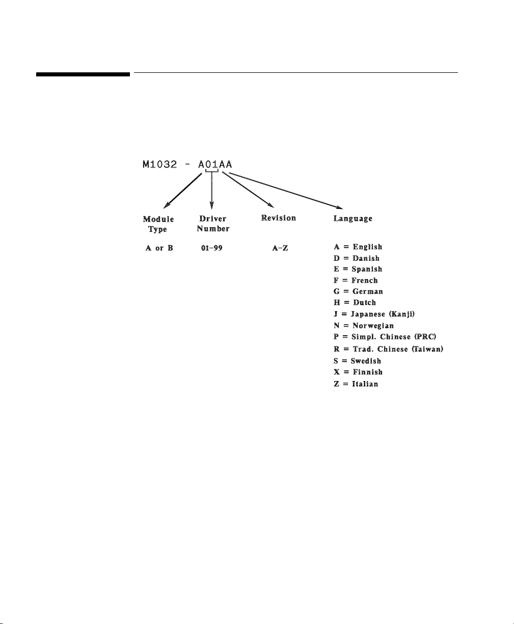
Driver Part Numbers for Supported Devices
Driver Part Numbers for Supported Devices
Each driver is allocated a part number, using the driver key detailed below:
16 Supported Device Information
Page 17

VueLink Cable Overview
3 Separate part numbers are assigned to each VueLink Cable:
M1032A KXX option To order a cable with a new module.
M1182A KXX option To order a cable for an existing module or for
M1032-XXXXX option To order a cable for an existing module from
The Supported Device cable options are detailed in the matrix opposite:
VueLink Cable Overview
VueLink Cable Overview
upgrades (Sales).
SMO/SLI. (Support or Immediate Requirement)
Device
New Module
Option (M1032A #)
Patient Monitor
Cable Option
(M1182A #)
SMO/SLI
(M1032-)
Option
2m 4m 2m 4m 2m 4m
Auxiliary Devices
Abbott Oximetrix 3 K73 - K73 - 61619 61620
Critikon 1846/1846 SX K72 - K72 - 61613 61614
Danmeter AAI/AEP Monitor K56 - K56 - 61693 -
Nellcor N-200 K71 - K71 - 61617 61618
Nellcor N-100C K70 - K70 - 61615 61616
Ventilators
Dräger Babylog 8000 - K2H - K2H - 61644
Dräger Evita K24 K2E K24 K2E 61629 61630
Dräger Evita 2 - K2G - K2G - 61643
Supported Device Information 17
Page 18

VueLink Cable Overview
VueLink Cable Overview
Patient Monitor
Cable Option
(M1182A #)
SMO/SLI
(M1032-)
Option
Device
New Module
Option (M1032A #)
2m 4m 2m 4m 2m 4m
Dräger Evita 2 dura
- K2M - K2M - 61680
Dräger Evita 4
Dräger Evita XL Ventilator
Dräger Graphic Screen for
- K29 - K29 - 61604
Babylog 8000
Dräger Graphic Screen for Savina - K28 - K28 - 61604
Dräger Savina - K27 - K27 - 61644
GE Engström Carestation - K2N - K2N - 61607
Hamilton Amadeus - 271 - 271 - 61673
Hamilton Veolar - 271 - 271 - 61673
Maquet Servo 300 - K2F - K2F - 61642
Maquet SERVO-i - K23 - K23 - 61696
Maquet SERVO-s - K26 - K26 - 61696
Nellcor Puritan Bennett 740 - K25 - K25 - 61665
Nellcor Puritan Bennett 760 - K25 - K25 - 61665
Nellcor Puritan Bennett 840 - K25 - K25 - 61665
Puritan-Bennett 7200a/ae K20 K2A K20 K2A 61621 61622
Siemens 900 C/D/E K21 K2B K21 K2B 61623 61624
Siemens SCM 990 K22 K2C K22 K2C 61625 61626
BEAR 1000 - K2K - K2K - 61657
18 Supported Device Information
Page 19

VueLink Cable Overview
VueLink Cable Overview
Device
New Module
Option (M1032A #)
Patient Monitor
Cable Option
(M1182A #)
SMO/SLI
Option
(M1032-)
2m 4m 2m 4m 2m 4m
Infrasonics Infant Star / ISV - K2J - K2J - 61645
Gas Analyzers
Datex Capnomac (II & Ultima) K41 - K41 - 61633 -
Dräger Vamos K4A - K4A - 61695 -
Philips M1025A/B K40 - K40 - 61631 -
Ohmeda RGM 5250 (old)
1
- - - - 61635 -
Ohmeda RGM 5250 (new) K43 - K43 - 61636 -
Ohmeda Rascal II K45 - K45 - 61664 -
Anesthesia Machines
Dräger Cato K02 - K02 - 61602 -
Dräger Cicero K01 - K01 - 61601 -
Dräger Cicero EM mono K10 - K10 - 61675 -
Dräger Cicero EM color - K12 K12 - 61685
Dräger Fabius GS/Tiro K49 - K49 - 61700 -
Dräger Julian K11 - K11 - 61681 -
Dräger Pallas K4C - K4C - 61694 -
Dräger PM 8050 270 - 270 - 61676 -
Dräger Primus/Apollo K48 - K48 - 61694 -
Dräger Zeus - K4B - K4B - 61666
Supported Device Information 19
Page 20

VueLink Cable Overview
VueLink Cable Overview
Device
New Module
Option (M1032A #)
Patient Monitor
Cable Option
(M1182A #)
SMO/SLI
(M1032-)
2m 4m 2m 4m 2m 4m
GE Aestiva K15 - K15 - 61684 -
GE Aisys K16 - K16 - 61684 -
GE Avance K15 - K15 - 61684 -
2
Narkomed 2B/2C
NAD
2
NAD
Narkomed 4
2
NAD
Narkomed GS
2
Narkomed 6000
NAD
K05 - K05 - 61605 -
K06 - K06 - 61605 -
K47 - K47 - 61605 -
K46 - K46 - 61605 -
Ohmeda Modulus CD K03 - K03 - 61603 -
Ohmeda 7800 K07 - K07 - 61658 -
Ohmeda 7810 K08 - K08 - 61659 -
Ohmeda 7900 K09 - K09 - 61678 -
Option
Taema Alys 274 - 274 - 61674 -
Auxiliary Plus Devices
Aspect Medical Systems
- K52 - K52 - 61687
A-2000 BIS Monitor
Baxter Explorer K74 - K74 - 61651 -
Baxter Vigilance - - - - 61652 -
B|Braun SpaceCom - K59 - K59 - 61649
Braun FM - 275 - 275 - 61691
20 Supported Device Information
Page 21

VueLink Cable Overview
VueLink Cable Overview
Device
New Module
Option (M1032A #)
Patient Monitor
Cable Option
(M1182A #)
SMO/SLI
Option
(M1032-)
2m 4m 2m 4m 2m 4m
Braun FM software revision < 3.0 - - - - - 61648
Diametrics Medical IRMA SL
- K54 - K54 - 61688
Series 2000
Diametrics Medical Trendcare
- K55 - K55 - 61689
monitor
Edwards CardiacOutput-
K75 - K75 - 61692 -
Oximetry Monitor Family
Fresenius Vial Base A/DPS/
- 277 - 277 - 61682
MVP
GE DINAMAP ProCare 100
- K78 - K78 - 61606
Series Patient Monitor
i-STAT
®
1 Analyzer
- K58 - K58 61667
Mortara ELI 100/STM - K76 - K76 - 61653
Organon Teknika
K53 - K53 - 61686 -
TOF-Watch SX
Free Analog Devices
Free Analog K60 K6A K60 K6A 61611 61612
Open Interface Cable (25-pin
- K6B - K6B - 61654
digital/analog)
Open Interface Cable (9-pin
- K6C - K6C - 61699
digital)
1. Old cable only available for support in case an existing cable fails.
2. NAD = North American Dräger
Supported Device Information 21
Page 22

VueLink Cable Overview
22 Supported Device Information
Page 23

Auxiliary Devices
Abbott Oximetrix 3 - SO2 Monitor
Device Driver Name: Abbott Oximetrix 3
Device Driver P/N: M1032-A07rl
Supported Devices: Oximetrix (R)3 SO
Connection: RS-232 Digital (Fixed configuration)
Switch Settings: Factory default
where:
r = revision
l = language
Monitor (version 104 and
2
105)
Baud Rate: 1200
Word Length: 8 bits
Stop Bits: 1
Start Bits: 1
Parity: None
A2
Auxiliary Devices 23
Page 24
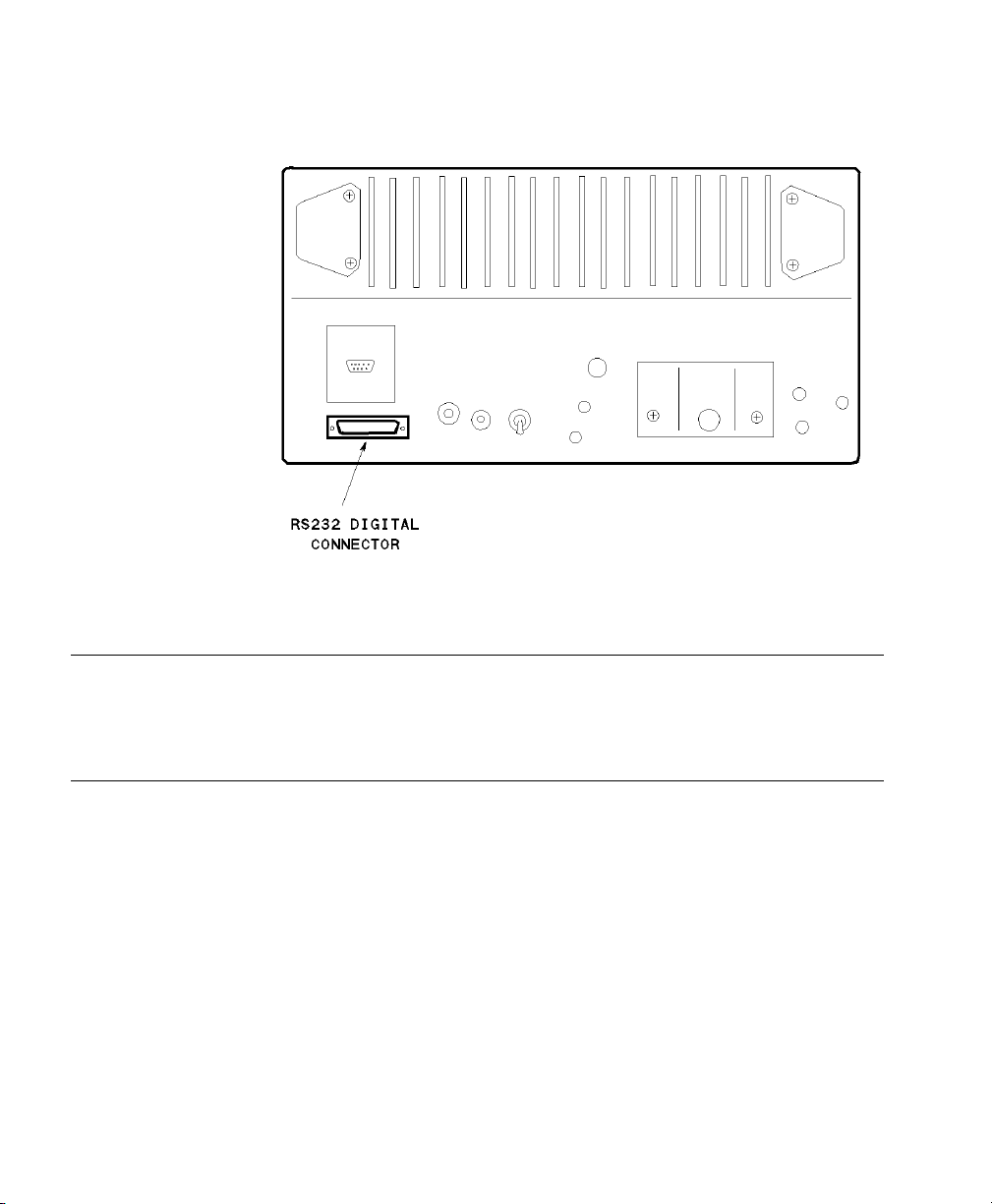
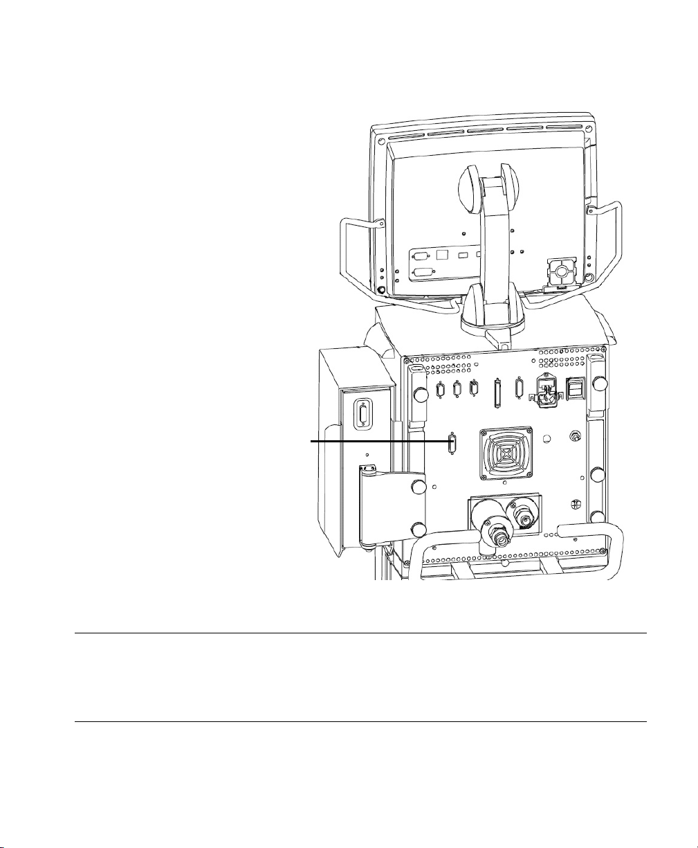
Abbott Oximetrix 3 - SO2 Monitor
Abbott Oximetrix 3 - SO2 Monitor Rear Panel
Note
Please refer to the Philips M1032A VueLink External Device Instructions for Use
for exact details of waves, numerics, INOPs and alarms available from the external
device and via Philips
24 Auxiliary Devices
patient monitoring network.
Page 25

Critikon Dinamap 1846 / 1846 SX - NBP Monitor
Critikon Dinamap 1846 / 1846 SX - NBP Monitor
Device Driver Name: Critikon 1846 / 1846 SX
Device Driver P/N: M1032-A06rl
where:
r = revision
l = language
Supported Devices: Critikon 1846 (with software revision 1846RCM
and 1846PRBG)
Critikon 1846 SX (with software revision SXRCH
and SXPRDH)
Connection: RS-232 Digital (Fixed configuration)
Baud Rate: 600
Word Length: 8 bits
Stop Bits: 1
Parity: None.
Switch Settings: Factory default
Auxiliary Devices 25
Page 26
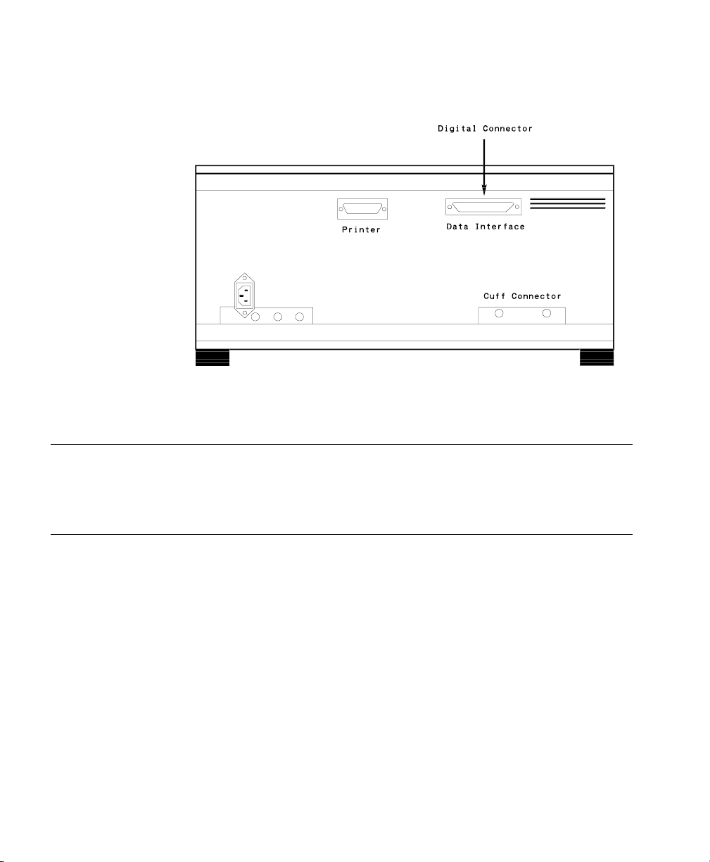
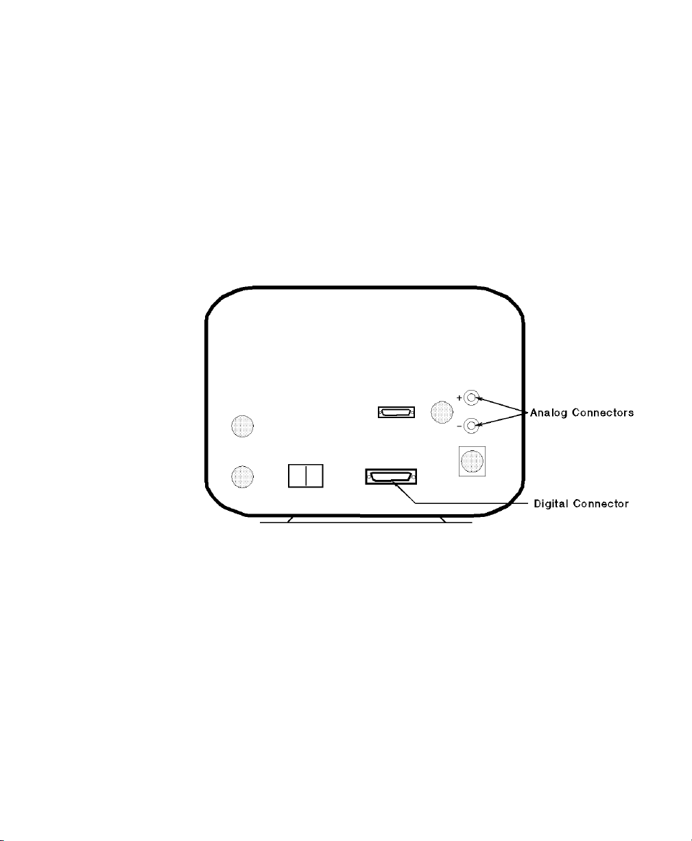
Critikon Dinamap 1846 / 1846 SX - NBP Monitor
Critikon Dinamap 1846 / 1846 SX - NBP Monitor Rear Panel
Note
Please refer to the Philips M1032A VueLink External Device Instructions for Use
for exact details of waves, numerics, INOPs and alarms available from the external
device and via Philips
26 Auxiliary Devices
patient monitoring network.
Page 27

Danmeter AAI/AEP Monitor
Device Driver Name: AAI/AEP Monitor
Device Driver P/N: M1032-A08rl
Supported Devices: Danmeter AAI/AEP Monitor (SBC(software)
Connection: RS-232 Digital (at the rear of the device)
Danmeter AAI/AEP Monitor
where:
r = revision.
l = language.
Version 1.5)
Baud Rate: 9600 (Low
1
)
Word Length: 8 bits
Stop Bits: 1
Start Bits: 1
Parity: None
Protocol: Device Link (ON
1
)
Danmeter AAI/AEP Monitor Rear Panel
1. Must be set and verified according to the document “AAI/AEP Monitor Directions for Use”.
Auxiliary Devices 27
Page 28

Danmeter AAI/AEP Monitor
Note Please refer to the Philips M1032A VueLink External Device Instructions for Use
for exact details of waves, numerics, INOPs and alarms available from the external
device and via Philips
patient monitoring network.
28 Auxiliary Devices
Page 29

Nellcor® N-200 - SpO2 Monitor
Device Driver Name: Nellcor® N-200
Device Driver P/N: M1032-A05rl
Supported Devices: Nellcor® N-200
Connection: Analog / RS-232 Digital combination
Switch Settings: See table below:
Name Number Position
Nellcor® N-200 - SpO2 Monitor
where:
r = revision
l = language
Baud Rate: 9600
Word Length: 8 bits
Stop Bits: 2
Parity: None
Analog: 1 alarm, 1 wave.
SCALE and OUTPUT VOLT Switches 1 UP
2 DOWN
DIP Switches 1 Either
2 DOWN
3 DOWN
4 UP
5 DOWN
6Either
7 UP
8 DOWN
Auxiliary Devices 29
Page 30
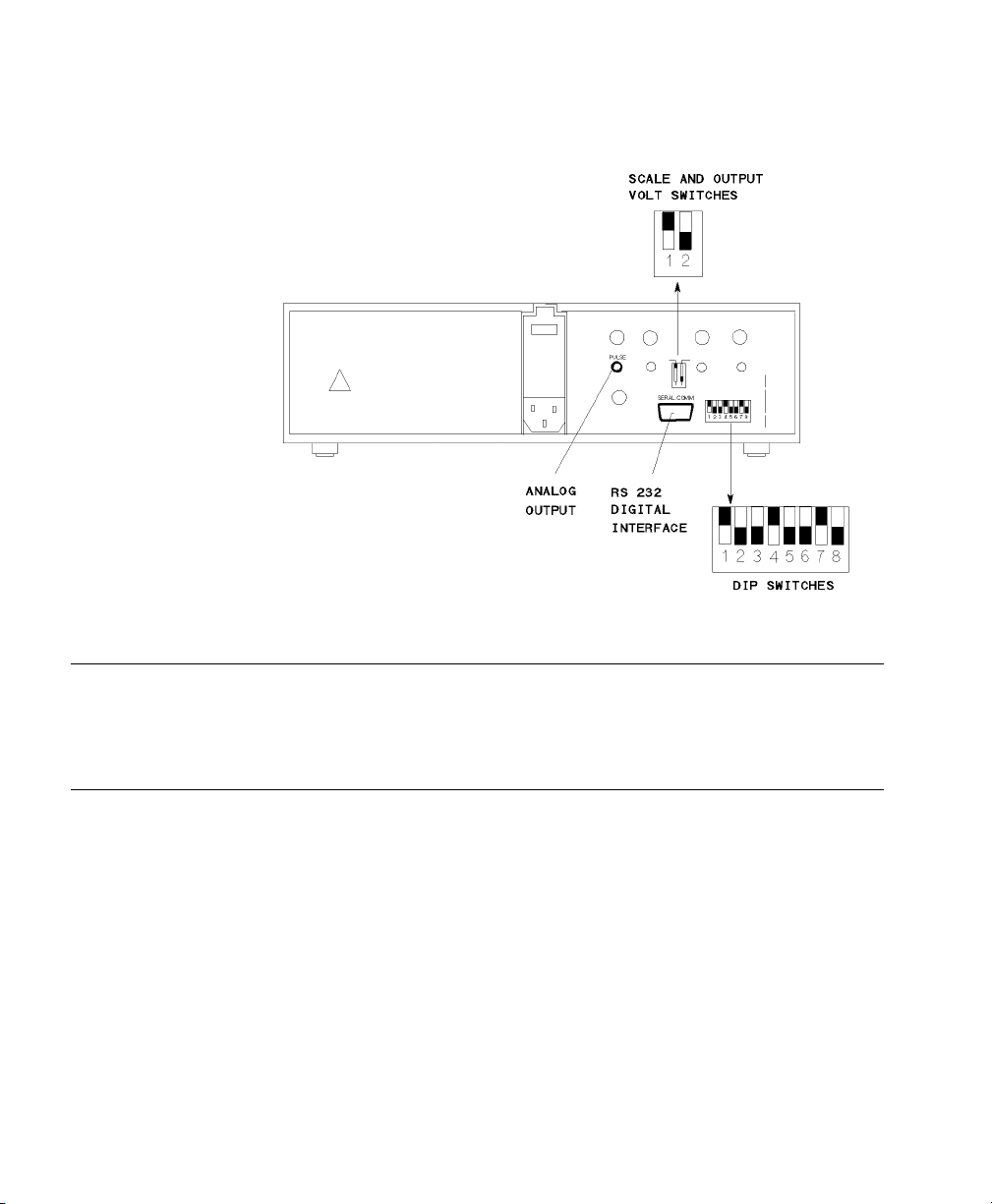
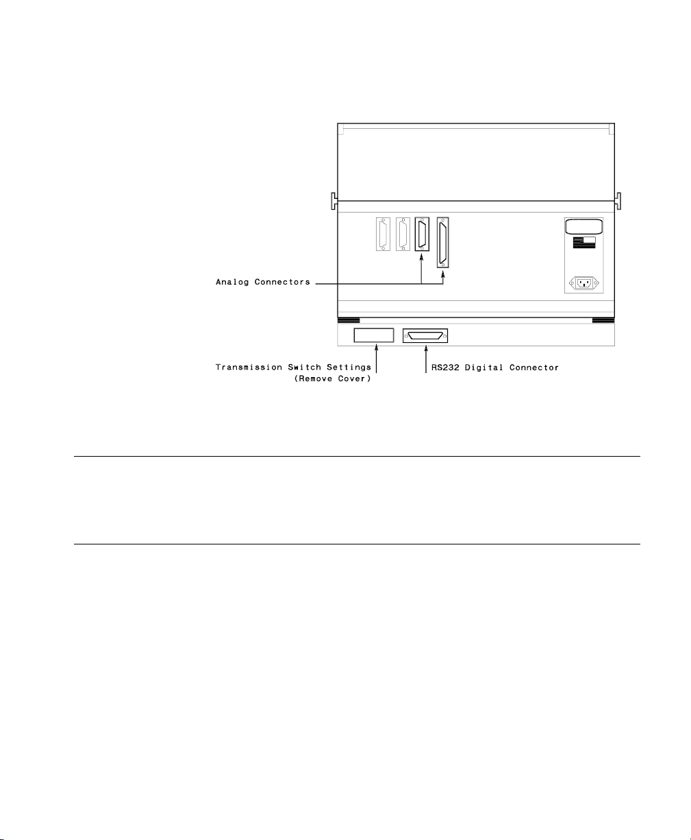
Nellcor® N-200 - SpO2 Monitor
Nellcor® N-200 - SpO2 Monitor Rear Panel
Note
Please refer to the Philips M1032A VueLink External Device Instructions for Use
for exact details of waves, numerics, INOPs and alarms available from the external
device and via Philips
30 Auxiliary Devices
patient monitoring network.
Page 31

Nellcor® N-100C - SpO2 Monitor
Device Driver Name: Nellcor® N-100
Device Driver P/N: M1032-A04rl
Supported Devices: Nellcor® N-100
Connection: Analog: 1 wave, 2 numerics, no alarms
Switch Settings: Set range switch to 0-10 V.
Nellcor® N-100C - SpO2 Monitor
where:
r = revision
l = language
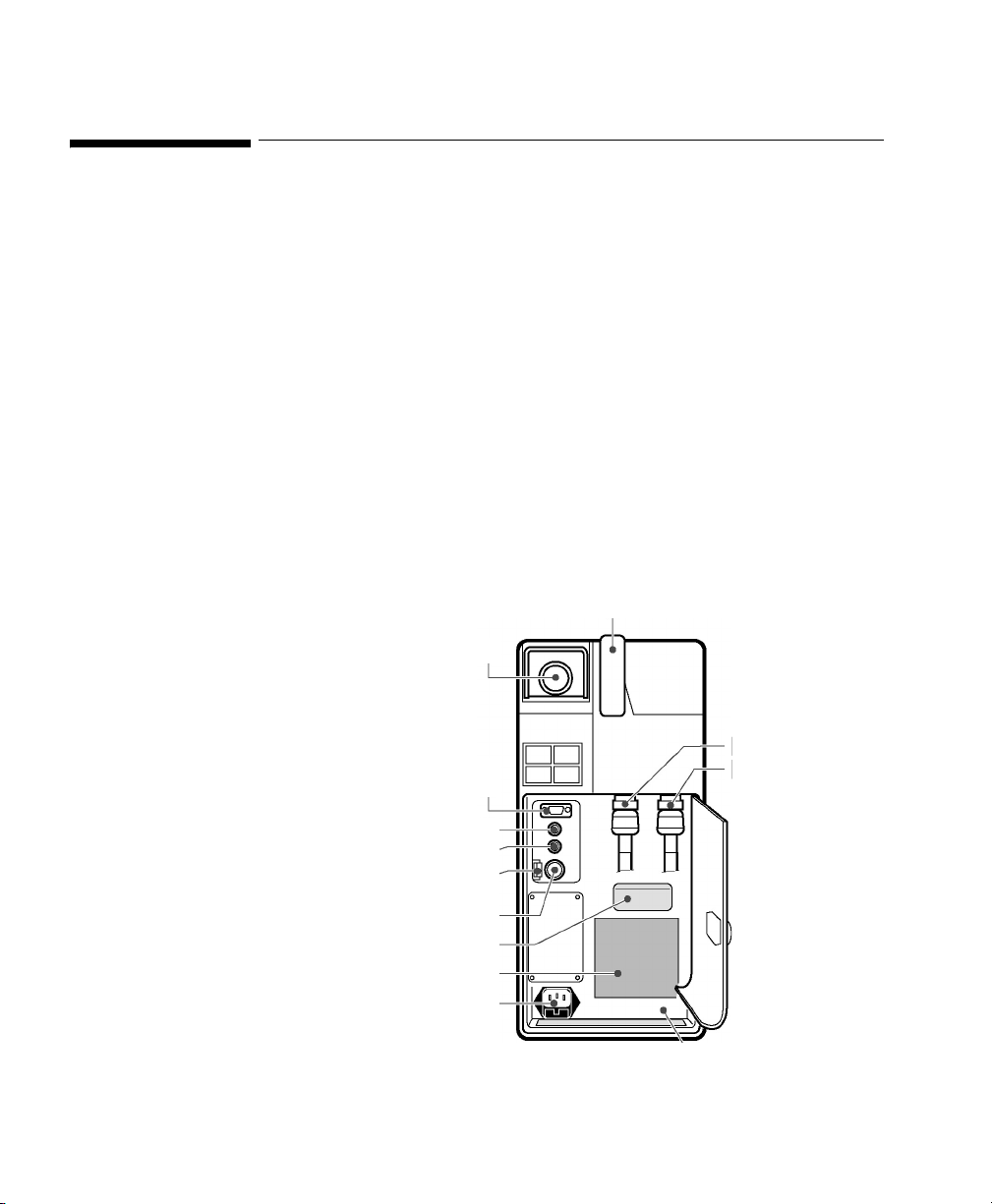
Nellcor® N-100C - SpO2 Monitor Rear Panel
Auxiliary Devices 31
Page 32

Nellcor® N-100C - SpO2 Monitor
Note The VueLink cable can get stuck in the outer cabinet without providing proper
contact to the connectors. Apply moderate force to overcome this problem.
Note Please refer to the Philips M1032A VueLink External Device Instructions for Use
for exact details of waves, numerics, INOPs and alarms available from the external
device and via Philips
patient monitoring network.
32 Auxiliary Devices
Page 33

Ventilators
Nellcor Puritan-Bennett 740 / 760 / 840 Ventilators
Device Driver Name: NPB740/760/840
Device Driver P/N: M1032-B48rl
where:
r = revision
l = language
Supported Devices: NPB 740 (sw rev. J).
NPB 760 (sw rev. J).
NPB 840 (sw rev. J).
Connection: RS-232 Digital
A3
Baud Rate: 9600
Word Length: 8 bits
Stop Bits: 1
Start Bits: 1
Parity: None
Note
Ventilators 33
RS-232 parameters must be set and verified according to the Nellcor PuritanBennett Service Manual
Page 34

Nellcor Puritan-Bennett 740 / 760 / 840 Ventilators
RS-232(A)
NPB 740 / 760 Ventilator Side Panel
RS-232
NPB 840 Ventilator Rear Panel
34 Ventilators
Page 35

Nellcor Puritan-Bennett 740 / 760 / 840 Ventilators
Note Please refer to the Philips M1032A VueLink External Device Instructions for Use
for exact details of waves, numerics, INOPs and alarms available from the external
device and via Philips
patient monitoring network.
Ventilators 35
Page 36

Puritan-Bennett 7200a / 7200ae Ventilator
Puritan-Bennett 7200a / 7200ae Ventilator
Device Driver Name: Bennett 7200a/ae
Device Driver P/N: M1032-B02rl
where:
r = revision
l = language
Supported Devices: Puritan-Bennett 7200a (sw rev. V English only).
Puritan-Bennett 7200ae (sw rev. D for Eng, Sp,
Fr, Ger and Ital).
Connection: Analog / RS-232 Digital combination
Baud Rate: 9600
Word Length: 7 bits
Stop Bits: 1
Parity: Even
Analog: 2 waves
Switch Setting: Internal; must be set by customer (see Puritan-
Bennett User Guide).
36 Ventilators
Page 37

Puritan-Bennett 7200a / 7200ae Ventilator
Puritan-Bennett 7200a / 7200ae Ventilator Rear Panel
Note
Please refer to the Philips M1032A VueLink External Device Instructions for Use
for exact details of waves, numerics, INOPs and alarms available from the external
device and via Philips
Ventilators 37
patient monitoring network.
Page 38

Dräger Babylog 8000 Ventilator
Dräger Babylog 8000 Ventilator
Device Driver Name: Dräger Babylog 8000 Ventilator
Device Driver P/N: M1032-B24rl
Supported Devices: Dräger Babylog 8000 with:
Supported Device Options: None
Connection: RS-232 Digital
where:
r = revision
l = language
• SW Revision: 5.01
• Digital Interface (optional): Babylink on
MEDIBUS protocol 3.00.
Baud Rate: 9600
1
Word Length: 8 bits (fixed)
Stop Bits: 1 (fixed)
1
Parity: None
Handshake: Software (fixed)
1
Protocol: MEDIBUS
(BabyLink)
Switch Settings: Factory default
1. Must be set and verified in accordance with Dräger Babylog 8000 User’s Manual.
38 Ventilators
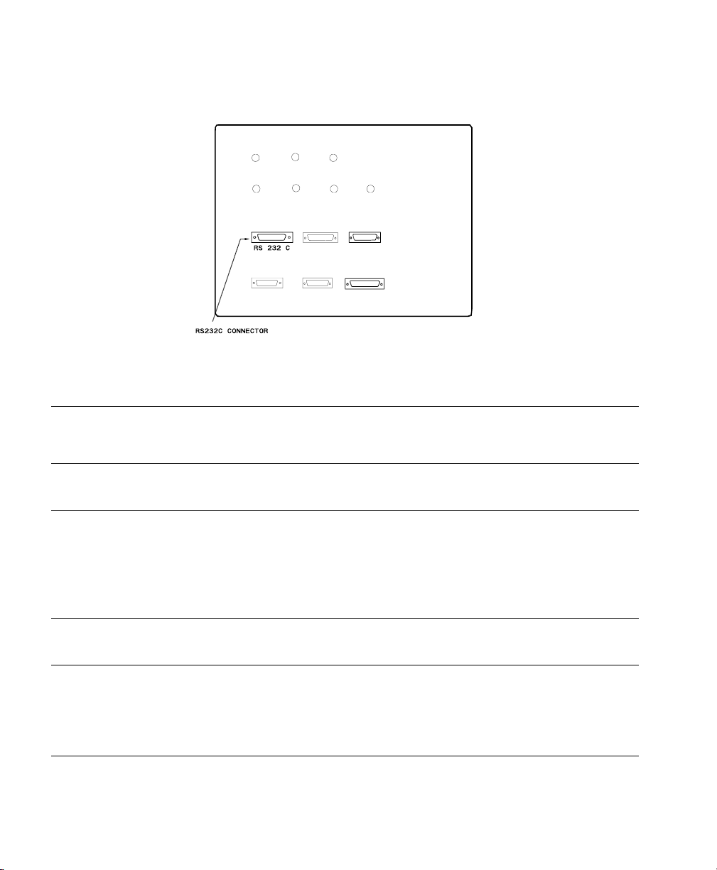
Page 39

RS-232
Connector
Dräger Babylog 8000 Ventilator
Dräger Babylog 8000 Rear Panel
Note
Please refer to the Philips M1032A VueLink External Device Instructions for Use
for exact details of waves, numerics, INOPs and alarms available from the external
device and via Philips
Ventilators 39
patient monitoring network.
Page 40

Dräger Evita Ventilator
Dräger Evita Ventilator
Device Driver Name: Dräger Evita Ventilator
Device Driver P/N: M1032-B11rl
Supported Devices: Dräger Evita Typ 8410614 with
Connection: Analog / RS-232 Digital combination exchange
where:
r = revision
l = language
• DW-Bus analog interface option number
8303940.
• digital interface option number 8305327
• SW Revision 11.01, 13.01 and 14.01, 13.02 or
14.02 for the digital interface and the Dräger
Evita Ventilator.
Baud Rate: 9600
Word Length 7 bits (fixed)
Stop Bits: 2 (fixed)
Parity: Even (fixed)
Handshake: Software (fixed)
Analog: 2 waves
Switch Settings: Factory default
40 Ventilators
Page 41

Dräger Evita Ventilator
Dräger Evita Ventilator Rear Panel
Note Please ensure that the first two digits of the software version number shown on the
Dräger Evita display after switching on the device are the same as the first two digits
of the version number on the Evita’s interface cards.
Note Please refer to the Philips M1032A VueLink External Device Instructions for Use
for exact details of waves, numerics, INOPs and alarms available from the external
device and via Philips
Ventilators 41
patient monitoring network.
Page 42

Dräger Evita 2 Ventilator
Dräger Evita 2 Ventilator
Device Driver Name: Dräger Evita 2 Ventilator
Device Driver P/N: M1032-B23rl
Supported Devices: Dräger Evita 2 with:
Supported Device Options: None
Connection: RS-232 Digital Channel A. (Channel B can also
where:
r = revision
l = language
• SW Revision 2.00.
• Digital interface (optional): EvitaLink 2.00 on
MEDIBUS protocol 3.00.
be used as an alternative when set up as follows.)
Baud Rate: 19200
1
Word Length: 8 bits (fixed)
Stop Bits: 1
Parity: Even
1
1
Handshake: Software (fixed)
Protocol: MEDIBUS
1
1. These settings are fixed for digital channel A. If channel B is used, they must be set and verified
according to the Dräger Evita 2 User’s Manual.
42 Ventilators
Page 43

Dräger Evita 2 Ventilator
Dräger Evita 2 Ventilator Rear Panel
Note
Please refer to the Philips M1032A VueLink External Device Instructions for Use
for exact details of waves, numerics, INOPs and alarms available from the external
device and via Philips
Ventilators 43
patient monitoring network.
Page 44

Dräger Evita 2 Dura, Dräger Evita 4 & Dräger Evita XL Ventilators
Dräger Evita 2 Dura, Dräger Evita 4 & Dräger Evita XL
Ventilators
Device Driver Name: Dräger Evita 2 DuraVentilator
Dräger Evita 4
Dräger Evita XL
Device Driver P/N: M1032-B41rl
where:
r = revision
l = language
Supported Devices: Dräger Evita 2 Dura with:
• SW Revision 4.10.
• MEDIBUS protocol 4.00.
Dräger Evita 4 with:
• SW Revision 4.10.
• MEDIBUS protocol 4.00.
Dräger Evita XL with:
• SW Revision 6.00.
• MEDIBUS protocol 4.00.
Supported Device Options: None
Connection: RS-232 C
Baud Rate: 19200
Word Length: 8 bits (fixed)
Stop Bits: 1
Parity: Even
Handshake: None
44 Ventilators
Page 45

Dräger Evita 2 Dura, Dräger Evita 4 & Dräger Evita XL Ventilators
com 1
Dräger Evita 2 Dura, Evita 4 and Evita XL Ventilator Rear Panel
Note
Please refer to the Philips M1032A VueLink External Device Instructions for Use
for exact details of waves, numerics, INOPs and alarms available from the external
device and via Philips
Ventilators 45
patient monitoring network.
Page 46

Dräger Graphic Screen for Babylog 8000
Dräger Graphic Screen for Babylog 8000
Device Driver Name: Dräger Graphic Screen for Babylog 8000
Device Driver P/N: M1032-B64rl
where:
r = revision
l = language
Supported Devices: Dräger Babylog 8000 Software 5.01
MEDIBUS Version 3.00.
Dräger Graphic Screen version 2.n
MEDIBUS Version 4.00.
Supported Device Options: None
Connection: RS-232 port COM3 on rear side of the Graphic
Screen
Baud Rate: 9600
Word Length: 8
Sart Bits: 1
Stop Bits: 1
Parity: None
Protocol: MEDIBUS
Note
46 Ventilators
All RS 232 port settings are fixed.
Page 47

Dräger Graphic Screen for Babylog 8000
Dräger Graphic Screen Rear Panel
Note
Please refer to the Philips M1032A VueLink External Device User's Information for
Dräger for Graphic Screen for Babylog 8000 for exact details of numerics, INOPs
and alarms available from the external device via Philips patient monitoring
network.
Ventilators 47
Page 48

Dräger Graphic Screen for Savina
Dräger Graphic Screen for Savina
Device Driver Name: Dräger Graphic Screen for Savina
Device Driver P/N: M1032-B63rl
Supported Devices: Dräger Savina Software 3.01
Connection: RS-232 port on rear side
where:
r = revision
l = language
MEDIBUS Version 4.00
Dräger Graphic Screen version 2.n
MEDIBUS Version 4.00.
Baud Rate: 19200
Data Bits: 8
Start Bits: 1
Stop Bits: 1
Parity: None
Protocol: MEDIBUS
Note
48 Ventilators
All RS 232 port settings are fixed.
Page 49

Dräger Graphic Screen for Savina
Dräger Graphic Screen Rear Panel
Note
Please refer to the Philips M1032A VueLink External Device User's Information for
Dräger for Graphic Screen for Savina for exact details of numerics, INOPs and
alarms available from the external device via Philips patient monitoring network.
Ventilators 49
Page 50

Dräger Savina
Dräger Savina
Device Driver Name: Dräger Savina
Device Driver P/N: M1032-B66rl
where:
r = revision
l = language
Supported Devices: Dräger Savina Software 3.01
MEDIBUS Version 4.00
Connection: RS-232 port on rear side
Baud Rate: 19200
Data Bits: 8
Start Bits: 1
Stop Bits: 1
Parity: None
Protocol: MEDIBUS
50 Ventilators
Page 51

RS 232
Dräger Savina
Dräger Savina Rear Panel
Note
Please refer to the Philips M1032A VueLink External Device User's Information for
Dräger for Savina for exact details of waves, numerics, INOPs and alarms available
from the external device via Philips patient monitoring network.
Ventilators 51
Page 52

GE Engström Carestation Ventilator
GE Engström Carestation Ventilator
Device Driver Name: GE Engström
Device Driver P/N: M1032-B67rl
where:
r = revision
l = language
Supported Devices: GE Engström Software 3.x
Ohmeda Com 1.3 Serial Protocol
Connection: RS-232 port on rear side (Port 4)
Baud Rate: 19200
Data Bits: 7
Start Bits: 1
Stop Bits: 1
Parity: Odd
52 Ventilators
Page 53
RS232
GE Engström Carestation Ventilator
GE Engström Carestation Ventilator Rear Panel
Note
Please refer to the Philips M1032A VueLink External Device Instructions for Use
for exact details of waves, numerics, INOPs, and alarms available from the external
device, and via Philips
Ventilators 53
patient monitoring network.
Page 54

Hamilton Veolar, Veolar FT, and Amadeus Ventilators
Hamilton Veolar, Veolar FT, and Amadeus Ventilators
Device Driver Name: Ve olar
1
Amadeus
Device Driver P/N: M1032-B19rl
where:
r = revision
l = language
Supported Devices: • Veolar and Veolar FT Ventilators
Control Processor and Front Panel
sw rev: V30 and V33
Interface sw rev: NIK01
• Amadeus Ventilator
Control Processor and Front Panel
sw rev: A31
Interface sw rev: NIK01
Connection: RS-232 Digital
Baud Rate:9600
2
Word Length: 7 bits (fixed)
Stop Bits: 2 bits (fixed)
Parity: EVEN (fixed)
Handshake: Flag control
Program Selector: Position 9
2
2
1. The product name Veolar is used throughout to describe both the Hamilton Veolar Ventilator,
and the Hamilton Veolar FT Ventilator.
2. Must be set by Hamilton Service Engineer before connecting to VueLink.
54 Ventilators
Page 55

Hamilton Veolar, Veolar FT, and Amadeus Ventilators
Hamilton Veolar Ventilator Rear Panel
Hamilton Amadeus Ventilator Rear Panel
Note
Please refer to the Philips M1032A VueLink External Device Instructions for Use
for exact details of waves, numerics, INOPs, and alarms available from the external
device, and via Philips
Ventilators 55
patient monitoring network.
Page 56

BEAR 1000 Ventilator
BEAR 1000 Ventilator
Device Driver Name: BEAR 1000
Device Driver P/N: M1032-B28rl
Supported Devices: Bear 1000 (Basic and Comprehensive) SW
Connection: Analog (2 waves) / RS-232 Digital combination.
where:
r = revision
l = language
Release 9.7
Bear GD 1000 Graphics Display (optional)
Software P/N 51001-02007
No graphics display:
Baud Rate: 9600 (Bear 1000 ventilator)
Graphics display:
Baud Rate: 19200 (Bear 1000 ventilator)
9600 (graphics display)
Word Length: 8-bits (fixed)
Stop Bits: 1 (fixed)
Parity: None (fixed)
The 15-pin connector should be connected to the analog port on the ventilator. The
9-pin connector should either be connected to the RS-232 port on the ventilator, if
56 Ventilators
Page 57

BEAR 1000 Ventilator
no Graphics Display is present, or to the Digital Out port on the Graphics Display.
In the latter case, the RS-232 gender adapter must also be used.
BEAR 1000 Ventilator Rear Panel
Note
Please refer to the Philips M1032A VueLink External Device Instructions for Use
for exact details of waves, numerics, INOPs and alarms available from the external
device and via Philips
Ventilators 57
patient monitoring network.
Page 58

Infrasonics® Infant Star / ISV Ventilator
Infrasonics® Infant Star / ISV Ventilator
Device Driver Name: Infrasonics® Infant Star / ISV
Device Driver P/N: M1032-B30rl
where:
r = revision
l = language
Supported Devices:
• Original Infant Star Ventilator (yellow casing):
• Standard Model TÜV Approved
• High Frequency Model TÜV
• Enh. High Frequency Model TÜV
(software version 49, 51)
Approved (software version 46, 50,
52)
Approved (software version 82, 83)
• New Infant Star ISV Ventilator (grey casing):
• Standard Model ISV 500 TÜV
Approved (software version 105, 107)
• High Frequency Model ISV 950
(software version 107)
58 Ventilators
Page 59
Infrasonics® Infant Star / ISV Ventilator
Connection: The device driver supports the following
configuration for the serial communications port:
Baud Rate: 1200
Word Length: 8 bits
Stop Bits: 2
Parity: None
Analog: 1 wave
These settings are fixed and cannot be changed.
Switch Settings: None
Original Infrasonics Infant Star Ventilator Rear Panel
Ventilators 59
Page 60

Infrasonics® Infant Star / ISV Ventilator
New Infrasonics Infant Star Ventilator Rear Panel
Note
Please refer to the Philips M1032A VueLink External Device Instructions for Use
for exact details of waves, numerics, INOPs and alarms available from the external
device and via Philips
60 Ventilators
patient monitoring network.
Page 61

Siemens SCM 990 Ventilator
Device Driver Name: Siemens SCM 990 AD (Adult)
Device Driver P/N: M1032-B08rl (Adult)
Supported Devices: Siemens 900 C/D/E with Servo Computer
Connection: Analog / RS-232 Digital combination
Siemens SCM 990 Ventilator
Siemens SCM 990 NEO (Neonatal)
M1032-B14rl (Neonatal)
where:
r = revision
l = language
Module 990 (serial number 713 or greater, sw rev
2.0).
Baud Rate: 9600
Word length : 8 bit s
Stop Bits: 1
Parity: Even.
Analog: 2 waves, 1 alarm,
1 numeric.
Switch Settings: See following table.
Transmission Switch Settings
Ventilators 61
Page 62

Siemens SCM 990 Ventilator
Transmission Switch Settings
Name
Switch
Number
Position
ADDRESS Code Switches 1 0-9 (ANY)
20-9 (ANY)
PARITY Switches (for RS-232
1ON
configuration)
2ON
3OFF
4OFF
BAUD RATE switch 1 5
Note The restart switch is to the right of the BAUD RATE switch. If any of the above
switches are changed during power-on; the device power must be switched off and
on.
62 Ventilators
Page 63
Siemens SCM 990 Ventilator
Siemens SCM990 Ventilator Rear Panel
Note
Please refer to the Philips M1032A VueLink External Device Instructions for Use
for exact details of waves, numerics, INOPs and alarms available from the external
device and via Philips
Ventilators 63
patient monitoring network.
Page 64

Siemens 900 C/D/E Ventilator
Siemens 900 C/D/E Ventilator
Device Driver Name: Siemens 900 C/D/E AD (Adult)
Siemens 900 C/D/E NEO (Neonatal)
Device Driver P/N: M1032-B03rl (Adult)
M1032-B07rl (Neonatal)
where:
r = revision
l = language
Supported Devices: Siemens 900 C/D/E
Connection: Analog: 2 waves, 5 numerics, 1 alarm.
Switch Settings: Factory default
Note Please ensure that the infant / adult switch on the Siemens Ventilator is in the
correct position.
64 Ventilators
Page 65

Siemens 900 C/D/E Ventilator
Siemens 900 C/D/E Ventilator Rear Panel
Note Please refer to the Philips M1032A VueLink External Device Instructions for Use
for exact details of waves, numerics, INOPs and alarms available from the external
device and via Philips
patient monitoring network.
Ventilators 65
Page 66

Maquet Servo 300/300A Ventilator
Maquet Servo 300/300A Ventilator
Device Driver Name: Maquet Servo 300/300A
Device Driver P/N: M1032-B20rl
Supported Devices: Maquet Servo 300/300A
Connection: Port N82 on rear side
where:
r = revision
l = language
Software revision 2.01
Baud Rate: 9600
1
Word length : 8 bit s
Stop Bits: 1
Parity: Even.
Protocol: SV300CI EXTENDED
1. Must be set and verified according to the Maquet Servo 300/300A User Manual
66 Ventilators
Page 67

Maquet Servo 300/300A Ventilator
Maquet Servo 300 Ventilator Rear Panel
Note
The analog cable previously connecting the VueLink module to port N81 is no
longer supported.
All waves and numerics are now transferred to the VueLink module using the digital
cable connected to port N82.
Note Please refer to the Philips M1032A VueLink External Device Instructions for Use
for exact details of waves, numerics, INOPs and alarms available from the external
device and via Philips
Ventilators 67
patient monitoring network.
Page 68
Maquet SERVO-i Ventilator
Maquet SERVO-i Ventilator
Device Driver Name: Maquet SERVO-i
Device Driver P/N: M1032-B55rl
Supported Devices: SERVO-i
Connection: Computer Interface Emulator
where:
r = revision
l = language
System version 2.0, 3.0
Baud Rate: 9600
Word length : 8 bit s
Start Bits: 1
Stop Bits: 1
Parity: Even
RS 232 Port
Maquet SERVO-i Ventilator Right Panel
68 Ventilators
Page 69

Maquet SERVO-i Ventilator
Note Please refer to the Philips M1032A VueLink External Device Instructions for Use
for exact details of waves, numerics, INOPs and alarms available from the external
device and via Philips
patient monitoring network.
Ventilators 69
Page 70

Maquet SERVO-s Ventilator
Maquet SERVO-s Ventilator
Device Driver Name: Maquet SERVO-s
Device Driver P/N: M1032-B65rl
Supported Devices: SERVO-s
Connection: Computer Interface Emulator
where:
r = revision
l = language
System version 3.0
Baud Rate: 9600
Word length : 8 bit s
Start Bits: 1
Stop Bits: 1
Parity: Even
70 Ventilators
Page 71

Maquet SERVO-s Ventilator
RS 232
Maquet SERVO-s Ventilator Back Panel
Note
Please refer to the Philips M1032A VueLink External Device Instructions for Use
for exact details of waves, numerics, INOPs and alarms available from the external
device and via Philips
Ventilators 71
patient monitoring network.
Page 72

Maquet SERVO-s Ventilator
72 Ventilators
Page 73

HP M1025A/B Gas Analyzer
Device Driver Name: Philips M1025A/B
Device Driver P/N: M1032-B06rl
Supported Devices: Philips M1025A (Protocol Rev. A, serial Number
Connection: RS-232 Digital
A4
Gas Analyzers
where:
r = revision
l = language
31xx and lower) and Philips M1025B.
Baud Rate: 9600
Parity: Even
Stop Bit: 1
Data Bit: 8
Handshake: Hardwired
Hardwire Mode: Switched Lines
Text Line: Ignore
Monitor Message: Ignore
Switch Settings: Use Philips M1025A/B screen configurations.
Gas Analyzers 73
Page 74

HP M1025A/B Gas Analyzer
Philips M1025A/B Gas Analyser Rear Panel
Note
Please refer to the Philips M1032A VueLink External Device Instructions for Use
for exact details of waves, numerics, INOPs and alarms available from the external
device and via Philips
patient monitoring network.
74 Gas Analyzers
Page 75

Datex Capnomac (II and Ultima) Gas Analyzer
Datex Capnomac (II and Ultima) Gas Analyzer
Start Up Procedure
The driver automatically identifies the connected device at start-up. For this reason,
the following start-up procedure must be followed whenever the user changes the
Datex Device, even if it is the same model:
1. Turn off the Datex Device.
2. Plug in and Set up the VueLink Module and connect the cable.
3. Turn on the Datex Device.
Note
Warning
To ensure proper operation of the VueLink module and accurate data, the start up
procedure described above must be carried out:-
• If the Datex device is turned off.
• If the VueLink module or cable is unplugged.
• Whenever the Datex device is selected.
• After re-entering monitoring mode.
• In order to avoid damaging the Datex device, the VueLink cable should
only be connected to, or disconnected from, the Datex device when it is
switched off.
Device Driver Name: DATEX
Device Driver P/N: M1032-B13rl
where:
r = revision
Gas Analyzers 75
Page 76

Datex Capnomac (II and Ultima) Gas Analyzer
Supported Devices: • Datex Capnomac II
Connection: Analog / RS-232 Digital combination
Switch Settings: Factory default
l = language
• Datex Capnomac II four channel analog
output option
•Datex Ultima
All units shipped after Feb 21st 1994
Baud Rate: 1200
Word Length: 8 bits
Stop Bits: 1
Parity: None
Analog: 1 wave on Capnomac II
3 waves on Capnomac II
four channel analog output option
4 waves on Capnomac
Ultima
76 Gas Analyzers
Page 77

Datex Capnomac (II and Ultima) Gas Analyzer
Datex Capnomac (II and Ultima) Gas Analyzer rear Panel
Note
Please refer to the Philips M1032A VueLink External Device Instructions for Use
for exact details of waves, numerics, INOPs and alarms available from the external
device and via Philips
Gas Analyzers 77
patient monitoring network.
Page 78

Dräger Vamos Variable Anaesthetic Gas Monitor
Dräger Vamos Variable Anaesthetic Gas Monitor
Device Driver Name: Dräger Vamos
Device Driver P/N: M1032-B54rl
where:
r = revision
l = language
Supported Devices: Dräger Vamos Software 2.0
MEDIBUS Version 4.03
Connection: MEDIBUS RS-232 port on rear side
Baud Rate: 9600
Data Bits: 8
Start Bits: 1
Stop Bits: 1
Parity: even
1
COM 1
(Medibus)
Dräger Vamos Rear Panel
1. Must be set and verified according to the Dräger Vamos User’s Manual.
78 Gas Analyzers
Page 79

Dräger Vamos Variable Anaesthetic Gas Monitor
Note Please refer to the Philips M1032A VueLink External Device Instructions for Use
for exact details of waves, numerics, INOPs and alarms available from the external
device and via Philips
patient monitoring network.
Gas Analyzers 79
Page 80

Ohmeda RGM 5250 Respiratory Gas Monitor
Ohmeda RGM 5250 Respiratory Gas Monitor
Device Driver Name: Ohmeda RGM 5250 Respiratory Gas Monitor
Device Driver P/N: M1032-B22Bl
where:
r = revision
l = language
Supported Devices: Ohmeda RGM 5250 with SW Revision 6.0
Supported Device Options: • Anesthetic Agent
•SpO
2
Connection: Analog / RS-232 Digital
Baud Rate: 1200
Word Length: 7 bits
Stop Bits: 1
Parity: Odd
Handshake: None
Hardwire mode: Uni-directional
Print Period: 10 sec
80 Gas Analyzers
Page 81

Ohmeda RGM 5250 Respiratory Gas Monitor
Ohmeda RGM 5250 Rear Panel
Note
Please refer to the Philips M1032A VueLink External Device Instructions for Use
for exact details of waves, numerics, INOPs and alarms available from the external
device and via Philips
Gas Analyzers 81
patient monitoring network.
Page 82

Ohmeda Rascal II Anesthetic Gas Monitor
Ohmeda Rascal II Anesthetic Gas Monitor
Device Driver Name: Ohmeda Rascal II
Device Driver P/N: M1032-B44rl
where:
r = revision
l = language
Supported Devices: Ohmeda Rascal II Anesthetic Gas Monitor with
SW Revision 1.12
Connection: RS-232 Digital and Analog
Baud Rate: 9600 (fixed)
Word Length: 8 bits (fixed)
Stop Bits: 1 (fixed)
Parity: None (fixed)
Ohmeda Rascal II Rear Panel
82 Gas Analyzers
Page 83

Ohmeda Rascal II Anesthetic Gas Monitor
Note Please refer to the Philips M1032A VueLink External Device Instructions for Use
for exact details of waves, numerics, INOPs and alarms available from the external
device and via Philips
patient monitoring network.
Gas Analyzers 83
Page 84

Ohmeda Rascal II Anesthetic Gas Monitor
84 Gas Analyzers
Page 85

Anesthesia Machines
Dräger Cato Anesthesia Device
Device Driver Name: Dräger Cato Anesthesia Device
Device Driver P/N: M1032-B25rl
Supported Devices: Dräger Cato - Screen Type PM 8050 CD with
Supported Device Options: None
A5
where:
r = revision
l = language
• SW Revision 2.01, 2.02
• Digital interface: MEDIBUS protocol 3.00
Connection: RS-232 Digital
Baud Rate: 9600
Word Length: 8 bits fixed)
Stop Bits: 1 (fixed)
Parity: Even (fixed)
Handshake: Software (fixed)
Protocol: MEDIBUS
1. Must be set and verified according to the Dräger Cato User's Manual.
Anesthesia Machines 85
1
1
Page 86

Dräger Cato Anesthesia Device
Dräger Cato Rear Panel
Note
Please refer to the Philips M1032A VueLink External Device Instructions for Use
for exact details of waves, numerics, INOPs and alarms available from the external
device and via Philips
patient monitoring network.
86 Anesthesia Machines
Page 87

Dräger Cicero Anesthesia Machine
Device Driver Name: Dräger Cicero Anesthesia Machine
Device Driver P/N: M1032-B12rl
Supported Devices: PM8020 datamanager
Connection: RS-232 Digital
Switch Settings: A jumper must be set inside the Cicero in order
Dräger Cicero Anesthesia Machine
where:
r = revision
l = language
Software revision 4.6 only
Baud Rate: 9600 (fixed)
Word Length: 8 bits fixed)
Stop Bits: 1 (fixed)
Parity: Even (fixed)
to get wave output. This must be done by your
local Dräger Representative.
Dräger Cicero Anesthesia Machine Rear Panel
Anesthesia Machines 87
Page 88

Dräger Cicero Anesthesia Machine
Note VueLink supports Isoflurane, Enflurane and Halothane gases only. If the Cicero is
configured with any other unsupported gas, Philips cannot accept any responsibility
for information displayed on the Philips patient monitor via VueLink.
Note Please refer to the Philips M1032A VueLink External Device Instructions for Use
for exact details of waves, numerics, INOPs and alarms available from the external
device and via Philips
patient monitoring network.
88 Anesthesia Machines
Page 89

Dräger Cicero EM Anesthesia Machine
Device Driver Name: Dräger Cicero EM Anesthesia Machine
Device Driver P/N: M1032-B36rl
where:
r = revision
l = language
Supported Devices: PM 8060 datamanager Software revision 2.01
only.
Connection: RS-232 Digital
Baud Rate: 9600
Word Length: 8 bits fixed)
Stop Bits: 1 (fixed)
Parity: Even (fixed)
Handshake: Software (fixed)
Protocol: MEDIBUS
Dräger Cicero EM Anesthesia Machine
1
1
1. Must be set and verified according to the Dräger Cicero EM User's Manual.
Anesthesia Machines 89
Page 90
Dräger Cicero EM Anesthesia Machine
Dräger Cicero EM Rear Panel
Note
To access the connectors, open the Cicero EM housing.
Note VueLink supports Isoflurane, Enflurane, Halothane, Sevoflurane, and Desflurane
gases only. If the Cicero EM is configured with any other unsupported gas, Philips
cannot accept any responsibility for information displayed on the Philips patient
monitor via VueLink.
Note Please refer to the Philips M1032A VueLink External Device Instructions for Use
for exact details of waves, numerics, INOPs and alarms available from the external
device and via Philips
90 Anesthesia Machines
patient monitoring network.
Page 91

Dräger Fabius GS/Tiro Anesthesia Machine
Dräger Fabius GS/Tiro Anesthesia Machine
Device Driver Name: Dräger Fabius GS/Tiro
Device Driver P/N: M1032-B53rl
where:
r = revision
l = language
Supported Devices: Dräger Fabius GS/Tiro Software 3.01
Connection: RS-232 port COM1
Baud Rate: 9600
Word Length: 8
Start Bits: 1
Stop Bits: 1
Parity: Odd
Protocol: Medibus
1
1.
1.
1.
1.
1. Must be set and verified according to the Dräger Fabius GS/Tiro Technical Service Manual.
Anesthesia Machines 91
Page 92

Dräger Fabius GS/Tiro Anesthesia Machine
Dräger Fabius GS/Tiro Rear Panel showing the location of COM1
Note
Please refer to the Philips M1032A VueLink External Device Instructions for Use
for exact details of waves, numerics, INOPs and alarms available from the external
device and via Philips
92 Anesthesia Machines
patient monitoring network.
Page 93

Dräger Julian Anesthesia Workstation
Device Driver Name: Dräger Julian
Device Driver P/N: M1032-B42rl
where:
r = revision
l = language
Supported Devices: PM 8055 datamanager
• Software Revision 3.02.
• Digital Interface: MEDIBUS Protocol 3.00.
Connection: RS-232 Digital
Baud Rate: 9600
Word Length: 8 bits (fixed)
Stop Bits: 1 (fixed)
Parity: Even (fixed)
Handshake: Software (fixed)
Protocol: MEDIBUS
Dräger Julian Anesthesia Workstation
1
1
1. Must be set and verified according to the Dräger Julian Anesthetic Workstation User's Manual.
Anesthesia Machines 93
Page 94

Dräger Julian Anesthesia Workstation
Dräger Julian Rear Panel
Note
VueLink supports Isoflurane, Enflurane, Halothane, Sevoflurane and Desflurane
gases only. If the Dräger Julian is configured with any other unsupported gas, Philips
cannot accept any responsibility for information displayed on the Philips patient
monitor via VueLink.
Note Please refer to the Philips M1032A VueLink External Device Instructions for Use
for exact details of waves, numerics, INOPs and alarms available from the external
device and via Philips
94 Anesthesia Machines
patient monitoring network.
Page 95

Dräger Pallas Anesthesia Workstation
Device Driver Name: Dräger Pallas
Device Driver P/N: M1032-B62rl
where:
r = revision
l = language
Supported Devices: Dräger Pallas Software 3.01
MEDIBUS Version 4.03
Connection: RS-232 port COM1 on rear side
Baud Rate: 9600
Data Bits: 8
Start Bits: 1
Stop Bits: 1
Parity: even
Protocol: MEDIBUS
Dräger Pallas Anesthesia Workstation
1
COM 1
(Medibus)
Dräger Pallas Rear Panel
Note
Please refer to the Philips M1032A VueLink External Device Instructions for Use
for exact details of waves, numerics, INOPs and alarms available from the external
device and via Philips
1. Must be set and verified according to the Dräger Pallas User’s Manual.
Anesthesia Machines 95
patient monitoring network.
Page 96

Dräger PM 8050 Anesthesia Machine
Dräger PM 8050 Anesthesia Machine
Device Driver Name: Dräger PM 8050
Device Driver P/N: M1032-B32rl
where:
r = revision
l = language
Supported Devices: Dräger PM 8050 with:
• Software Revision 2.02, 2.03.
• Digital Interface: MEDIBUS Protocol 3.00.
Connection: RS-232 Digital
Baud Rate: 9600
Word Length: 8 bits (fixed)
Stop Bits: 1 (fixed)
Parity: Even (fixed)
Handshake: Software (fixed)
Protocol: MEDIBUS
1
1
1. Must be set and verified according to the Dräger PM 8050 User's Manual.
96 Anesthesia Machines
Page 97

Dräger PM 8050 Anesthesia Machine
Dräger PM 8050 Rear Panel
Note
VueLink supports Isoflurane, Enflurane, Halothane, Sevoflurane and Desflurane
gases only. If the Dräger PM
8050 is configured with any other unsupported gas,
Philips cannot accept any responsibility for information displayed on the Philips
patient monitor via VueLink.
Note Please refer to the Philips M1032A VueLink External Device Instructions for Use
for exact details of waves, numerics, INOPs and alarms available from the external
device and via Philips
patient monitoring network.
Anesthesia Machines 97
Page 98

Dräger Primus/Apollo Anesthesia Workstation
Dräger Primus/Apollo Anesthesia Workstation
Device Driver Name: Dräger Primus/Apollo
Device Driver P/N: M1032-B52rl
where:
r = revision
l = language
Supported Devices: Dräger Primus Software 2.02
MEDIBUS Version 4.03
Dräger Apollo Software 3.0
MEDIBUS Version 4.03
Connection: RS-232 port COM1 on rear side
Baud Rate: 9600
Data Bits: 8
Start Bits: 1
Stop Bits: 1
Parity: even
Protocol: MEDIBUS
1
1. Must be set and verified according to the Dräger Primus/Apollo User’s Manual.
98 Anesthesia Machines
Page 99

Dräger Primus/Apollo Anesthesia Workstation
COM 1
(Medibus)
Dräger Primus/Apollo Rear Panel
Note
Please refer to the Philips M1032A VueLink External Device Instructions for Use
for exact details of waves, numerics, INOPs and alarms available from the external
device and via Philips
Anesthesia Machines 99
patient monitoring network.
Page 100

Dräger Zeus Anesthesia Device
Dräger Zeus Anesthesia Device
Device Driver Name: Dräger Zeus
Device Driver P/N: M1032-B58rl
Supported Devices: Dräger Zeus Software 3.n
Connection: RS-232 port COM1 or COM2 on rear side
where:
r = revision
l = language
• MEDIBUS Version 4.03
Baud Rate: 9600
1
Word Length: 8
Stop Bits: 1
Parity: Even
Protocol: MEDIBUS
1. Must be set and verified according to the Dräger Zeus User's Manual.
100 Anesthesia Machines
 Loading...