

Philips HTS3270/12/05, HTS3269/12, HTS3277/12, HTS3270, HTS3270/12 Service Manual
...
©
Copyright 2009 Philips Consumer Electronics B.V. Eindhoven, The Netherlands
All rightsreserved. No part of this publication may be reproduced, stored in a retrieval system or
transmitted, in any form or by any means, electronic, mechanical, photocopying, or otherwise
without the prior permission of Philips.
Published by ET-SL0906 Service Audio Printed in The Netherlands Subject to modification
HTS3270/12/05
DVD Home Theatre System
© 3141 785 33330
Version 1.0
TABLE OF CONTENTS
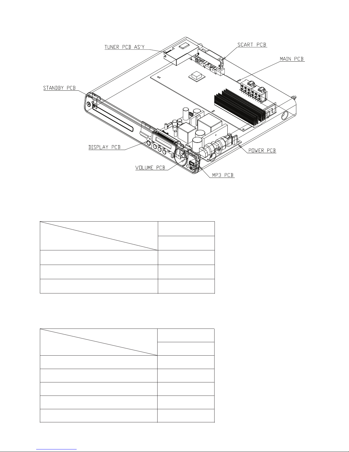
Location of PCB Boards ............................................ 1-2
Versions Variation ...................................................... 1-2
Measurement Setup .................................................. 1-4
Specifications ............................................................ 1-3
Service Aids .............................................................. 1-5
ESD & Safety Instruction .......................................... 1-6
Lead-free soldering Information ................................ 1-7
Setting procedure & Repair Instructions........................ 2
Disassembly I n s tructions & Service positions ..............3
Block & Wiring Diagram ................................................ 4
DISP+LED+VOL Board.................................................. 5
MAIN Board....................................................................6
Power Board .................................................................. 7
MP3 IN Board ................................................................ 8
Mechanical Exploded View & Part List........................10
Scart Board.................................................................... 9
Revision List ................................................................11
Chapter
1 - 2
LOCATION OF PCB BOARDS
VERSION VARIATION:
Type/Versions
Features
HTS3270
Output Power - 420W
Voltage (110~240V)
MP3 Link
MAIN Board
DISP+LED+VOL Board
Scart Board
Type/Versions
Board in used
HTS3270
C
C
C
/12/05
SERVICE SCNARIO MATRIX:
/12/05
x
x
x
*C = Component Level Repair
Power Board
C
MP3 IN Board
C

1 - 3
SPECIFICATIONS
Playback media
DVD-Video, DVD+R/+RW, DVD-R/-RW, DVD+R DL, CD-R/
CD-RW, Audio CD, Video CD/SVCD, Picture CD, MP3-CD,
WMA-CD, DivX-CD, USB ash drive
Amplifier
Total output power . . . . . . . . . . . . . . . . . . . . . . . . . . . . . . . . . . . . . . . . . . . . . . . . . . . . . . . . . . . . . . . ......
Home Theatre mode . . . . . . . . . . . . . . . . . . . . . . . . . 420 W(2 X 100 + 4 X 55)
Frequency response . . . . . . . . . . . . . . . . . . . . . . . . . . . . . . . . . . . . . . . . . . 40 Hz ~ 20 kHz
Signal-to-noise ratio . . . . . . . . . . . . . . . . . . . . . . . . . . . . . . . . . . . . . . . . . . . . . . . . . . . . . . > 60 dB
............................................................................... (A-weighted)
Input sensitivity . . . . . . . . . . . . . . . . . . . . . . . . . . . . . . . . . . . . . . . . . . . . . . . . . . . . . . . . . . . . . . . . . . . . ......
AUX . .. . .. . .. . .. ... . .. . .. ... . .. . .. . .. ... . .. . .. ... . .. . .. . .. ... . .. . .. ... . .. . .. . .. ... . 400 mV
SCART TO TV . . . . . . . . . . . . . . . . . . . . . . . . . . . . . . . . . . . . . . . . . . . . . . . . . . . . . . . . . . . . . . . 250 mV
MP3 LINK . .. . .. ... . .. ... . .. ... . .. ... . .. ... . .. ... . .. ... . .. ... . .. ... . .. ... . .. ... . 250 mV
Disc
Laser Type . . . . . . . . . . . . . . . . . . . . . . . . . . . . . . . . . . . . . . . . . . . . . . . . . . . . . . . . Semiconductor
Disc diameter . . . . . . . . . . . . . . . . . . . . . . . . . . . . . . . . . . . . . . . . . . . . . . . . . . . . . . . . . . . 12cm / 8cm
Video decording . . . . . . . . . . . . . . . . . . . . . . . . . . . . . . . . . . . . MPEG1/ MPEG2 / DivX
................................................................................. / DivX Ultra
Video DAC . . . . . . . . . . . . . . . . . . . . . . . . . . . . . . . . . . . . . . . . . . . . . . . . . . . . . . 12 bits, 108 MHz
Signal system . .. . .. .. . .. . .. ... . .. ... ... . .. ... ... . .. .. . .. . .. ... . .. ... .. PAL / NTSC
Video S/N ..... ........... ........ ........... ........ ........... ................... 56 dB
Audio DAC . . . . . . . . . . . . . . . . . . . . . . . . . . . . . . . . . . . . . . . . . . . . . . . . . . . . . . . . . 24 bits / 96 kHz
Frequency response . . . . . . . . . . . . . . . . . . . . . . . . . . . . . . . . . . . . . . . . . . . . . . . . . . . . . . . . . . . . ......
............................................................ 4 Hz - 20 kHz (44.1 kHz)
............................................................... 4 Hz - 22 kHz (48 kHz)
............................................................... 4 Hz - 44 kHz (96 kHz)
PCM . . . . . . . . . . . . . . . . . . . . . . . . . . . . . . . . . . . . . . . . . . . . . . . . . . . . . . . . . . . . . . . . . . . . . . . . . . IEC 60958
Dolby Digital ........ ................. .............. ... IEC 60958, IEC 61937
DTS ..... ........... ........ ........... ........ ........... . IEC 60958, IEC 61937
Radio
Tuning range ..... ........... ........ ........ FM 87.5–108 MHz (50 kHz)
2 6 dB quieting sensitivity . . . . . . . . . . . . . . . . . . . . . . . . . . . . . . . . . . . . . . . . . . FM 22 dBf
IF rejection ratio . . . . . . . . . . . . . . . . . . . . . . . . . . . . . . . . . . . . . . . . . . . . . . . . . . . . . . . . . . FM 60 dB
Signal-to-noise ratio . . . . . . . . . . . . . . . . . . . . . . . . . . . . . . . . . . . . . . . . . . . . . . . . . . . . FM 50 dB
Harmonic distortion . . . . . . . . . . . . . . . . . . . . . . . . . . . . . . . . . . . . . . . . . . . . . . . . . . . . . . . . . FM 3%
Frequency response . . . . . . . . . . . . . . . . . . . . . . . . . . . . . . . . . . . . FM 180 Hz~10 kHz
........................................................................................./ ±6dB
Stereo separation . .. . .. ... . .. ... . .. ... . .. ... . .. ... . .. ... . .. FM 26 dB (1 kHz)
Stereo Threshold . . . . . . . . . . . . . . . . . . . . . . . . . . . . . . . . . . . . . . . . . . . . . . . . . . . . . . . . FM 29 dB
USB
C ompatibility . . . . . . . . . . . . . . . . . . . . . . . . . . . . . . . . . . . . . . . . . . . . . . Hi-Speed USB (2.0)
Class support . . . . . . . . . . . . . . . . . . . . . . . . . UMS (USB Mass Storage Class)
File system ........ ................. .............. ... .. FAT12, FAT16, FAT32
Main Unit
Power supply . . . . . . . . . . . . . . . . . . . . . . . . . . . . . . . . . . . . . . . . 110–240 V; ~ 50–60 Hz
Power consumption . . . . . . . . . . . . . . . . . . . . . . . . . . . . . . . . . . . . . . . . . . . . . . . . . . . . . . . . . . . 80 W
Standby power consumption . .. ... ... ... . .. .. . .. . .. .. . .. . .. .. . .. . .. .. . . < 1 W
Dimensions (WxHxD) . .. .. ... ... .. . .. .. ... .. . .. .. ... 360 x 57 x 331 (mm)
Weight ..... ........... ........ ........... ........ ........... ................... ...2.87 kg
Speakers
System . . . . . . . . . . . . . . ............................................. full range satellite
Speaker impedance . . . . . . . . . . . . 4 ohm (centre),8 ohm (Front/Rear)
Speaker drivers ........ .................................................................
Centre/Front/Rear . . . . . . . . . . . . . . .................................. 3” full range
Frequency response . . . . . . . . . . . . . . ..........................150 Hz ~ 20 kHz
Dimensions (WxHxD) . .. .. ... ... .. ...................................................
- Centre/Front/Rear ........... ... ............... 100 x 100 x 75 (mm)
Weight ..... ..................................................................................
- Centre . . . . . . . . . . . . . . ........................................................0.66 kg
- Front . . . . . . . . . . . . . . ..........................................................0.39 kg
- Rear . . . . . . . . . . . . . . ...........................................................0.38 kg
Subwoofer
Impedance . . . . . . . . . . . . . . ......................................................... 4 ohm
Speaker drivers ........ ............................... 165 mm (6.5”) woofer
Frequency response . . . . . . . . . . . . . . ............................40 Hz ~ 150 Hz
Dimensions (WxHxD) . .. .. ... ... .. ................ 123 x 310 x 369 (mm)
Weight ..... ...................................................................... 3.88 Kg
Laser specification
Type . . . . . . . . . . . . . . ...................... Semiconductor laser GaAIAs (CD)
Wave length . . . . . . . . . . . . . . .. 645 - 665 nm (DVD),770 - 800 nm (CD)
Output power . . . . . . . . . . . . . . ................6 mW (DVD),7 mW (VCD/CD)
Beam divergence . . . . . . . . . . . . . . ..................................... 60 degrees.
Speci cations subject to change without prior notice.
1 - 4
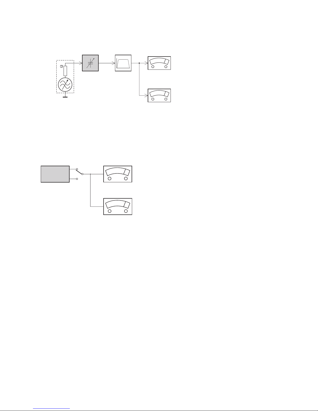
LEVEL METER
e.g. Sennheiser UPM550
with FF-filter
S/N and distortion meter
e.g. Sound Technology ST1700B
L
R
DUT
CD
Use Audio Signal Disc
(replaces test disc 3)
SBC429 4822 397 30184
Bandpass
250Hz-15kHz
e.g. 7122 707 48001
LF Voltmeter
e.g. PM2534
DUT
RF Generator
e.g. PM5326
S/N and distortion meter
e.g. Sound Technology ST1700B
Use a bandpass filter to eliminate hum (50Hz, 100Hz) and disturbance from the pilottone (19kHz, 38kHz).
Ri=50
Tuner FM
MEASUREMENT SETUP
1 - 5
Service Tools:
Universal Torx driver holder .................................4822 395 91019
Torx bit T10 150mm ...........................................4822 395 50456
Torx driver set T6-T20 .........................................4822 395 50145
Torx driver T10 extended .....................................4822 395 50423
Compact Disc:
SBC426/426A Test disc 5 + 5A ...........................4822 397 30096
SBC442 Audio Burn-in test disc 1kHz .................4822 397 30155
SBC429 Audio Signals disc .................................4822 397 30184
Dolby Pro-logic Test Disc ....................................4822 395 10216
SERVICE AIDS
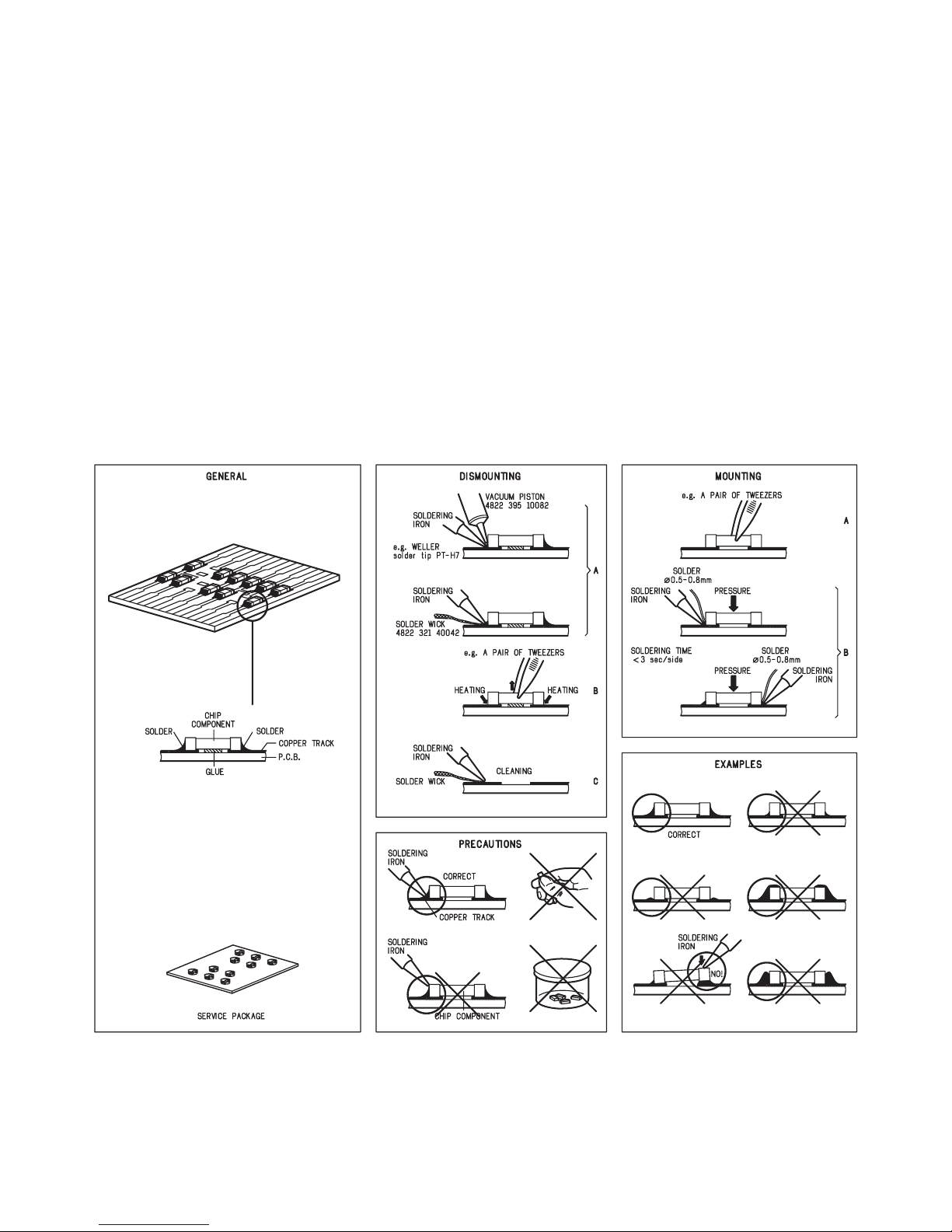
HANDLING CHIP COMPONENTS
1 - 6
1 - 7
2 - 12 - 1
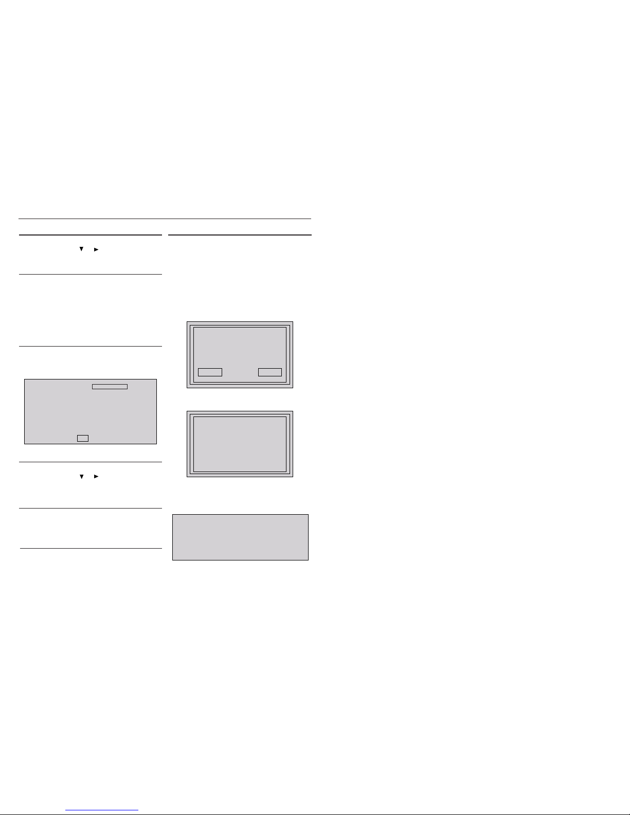
System , Region Code , etc. Setting Produre
1)System Reset
a) Press “SETUP“ button on R/C,TV will show setup menu
b) Select the menu using the and
on R/C
c) Go preference page to do system reset
2)Region Code Change
a) In open mode, press”9” “9“ “9“ “9“ on R/C,then input desired
number to change region code :
1 USA
2 EU
3 AP
4 Australia ,NZ , Latam
5 Russia , INDIA
6 CHINA
3)Version Control Change
a) In open mode, press “1“ “5“ “9“ on R/C
b) Press “ok” button to con rm
c) TV will show message as below:
7) Upgrading new software
a) Copy “software les” into a CD-R
b) Open the CD Door,then insert the CD-R program disc
c) Close the CD Door
d) VFD will show:
“Loading“
“Erase” -- erase the ash memory
“Writing” about 1 minute
“done “
* the system will switch off and on again automatically.
e) OSD will show:
Current model HTS3270/12/05
Version: XX.XX.XX Release:XXXX.XX.XX
region :2 Servo:XX.XX.XX.XX
8032:XX.XX.XX.XX RISC: XX.XX.XX.XX
MCU:XX.XX
If current model does not match you set use down arrow
key on the remote to change
OK
CAUTION!
This information is confi dential and may not be
distributed.Only a qualifi ed se rvice person should
reprogram the Region Code.
4)Password Change
a) Press “SETUP“ button on R/C,TV will show setup menu
b) Select the menu using the and on R/C
c) Go preference page select “password“ to change
* 000000 is default password supplied.
5)Check on the Software Version
a) Open the CD Door
b) Press “INFO“ button on R/C
c) TV will show the version on screen
upgrade le detected
Do you wish to continue with
the software upgrade?
OK Cancel
f) Select “OK”, OSD will show:
upgrade in progress...
V327X
please do not unplug or
switch off the device.
6)Trade model
a) Press “Open/Close “ button on R/C
b) Press “2” “5” “9” on R/C,VFD will display “TRA ON “ or “TRA
OFF“
2 - 22 - 2
REPAIR INSTRUCTIONS (ONE)
2 - 32 - 3
REPAIR INSTRUCTIONS (TWO)
2 - 42 - 4
REPAIR INSTRUCTIONS (THREE)
3 - 1 3 - 1
DISASSEMBLY INSTRUCTIONS
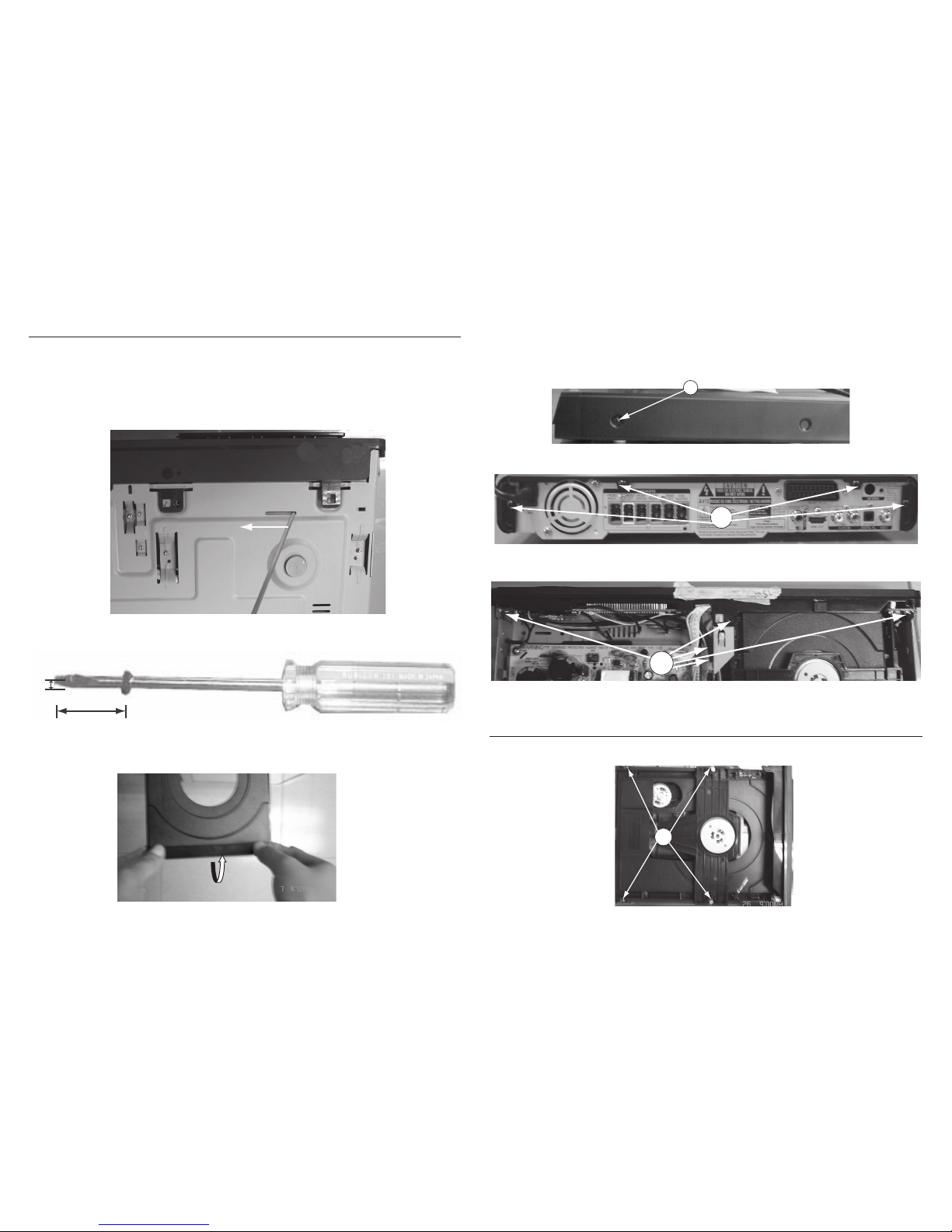
3) Loosen 6 screws and remove the Top Cover by lifting the rear portion upwards before sliding it out towards the rear.
- 1 screw “A” each on the left & right side as shown in gure 4.
- 4 screws “B” at the back panel as shown in g ure 5.
4) Loosen 5 screws “C“ at the front panel bracket as in g ure 6 to remove the front panel.
24mm
mm2
Figure 2
Dismantling of the Front Panel Assemble
1) Open the DVD Tray by using the Open/Close Button while the Set is ON and disconnect the mains supply after removing the Tray
Cover.
Note: If this is not possible, the DVD Tray has to be open manually.
Take a mini screw driver about 2mm diameter and make a marking 24mm from the tip as shown in gure 2 . Place the set on its
side, insert the mini screw driver till the marking and slide it towards the left as shown in gure 1 until the Tray moves out of the Front
Panel.
2) Return the set to its upright position and remove the Tray Cover as shown in Figure 3 and close the tray manually by pushing it back
in.
Figure 1
Qvti
Figure 3
Figure 4
A
Figure 5
B
Figure 6
C
Dismantling of the DVD Module
1) Loosen 4 screws “ D “ at the DVD Module as shown in gure 7.
Figure 7
D
 Loading...