

Page 1
M3535A/M3536A
Instructions for Use
HeartStart MRx
Page 2

Page 3

1Table of Contents
1 Introduction 3
Overview 3
Intended Use 5
Defibrillation Therapy 5
Synchronized Cardioversion Therapy 5
Noninvasive Pacing Therapy (Optional) 5
12-Lead ECG Analysis (Optional) 6
Noninvasive Blood Pressure (NBP) Monitoring (Optional) 6
CO2 Monitoring (Optional) 6
Pulse Oximetry (SpO2) Monitoring (Optional) 6
Indications for Use 7
Safety Considerations 8
Documentation and Training 8
2 Getting Acquainted 9
Basic Orientation 10
Front Panel 10
Side Panels 11
Top Pa n e l 12
Back Panel 13
M3538A Lithium Ion Battery 14
Battery Capacity 14
Battery Life 14
Operating Modes 14
Password Security 15
Display Views 15
General Status 16
Wave Se ct or s 17
Parameter Blocks 18
Soft Key Labels 18
Display Menus 19
Message Windows 19
High Contrast Display 20
Controls 20
Therapy Knob 20
General Function Buttons 21
Defibrillation Controls 22
Soft Keys 22
Indicators 23
i
Page 4

Responding to Alarms 24
Entering Patient Information 25
Continued Use 25
Return to Owner 26
3 Setting Up 27
Attaching the Carrying Case and Accessory Pouches 27
Storing Accessories 29
Connecting the ECG Cable 31
Connecting the SpO2 Cable 32
Connecting the NBP Interconnect Tubing 33
Connecting the CO2 Nasal FilterLine
Connecting the Therapy Cable 35
Installing Paper 36
50mm Printer 36
75mm Printer 37
Installing Batteries 38
Charging Batteries 38
Battery Safety 38
Installing the AC Power Module 39
Installing the Data Card 40
®
34
4 ECG and Arrhythmia Monitoring 41
Overview 41
Monitoring View 42
Preparing to Monitor ECG 43
Electrode Placement 45
Lead Selection 47
Lead Choices 47
Selecting the Lead 48
Arrhythmia Monitoring 48
Aberrantly-Conducted Beats 49
Intermittent Bundle Branch Block 49
Heart Rate and Arrhythmia Alarms 50
Arrhythmia Alarm Latching 50
INOP Messages 51
Setting Alarms 52
Changing Heart Rate or Vtach Alarm Limits 52
Enabling/Disabling Heart Rate and Arrhythmia Alarms 52
Responding to HR and Arrhythmia Alarms 52
Displaying an Annotated ECG 53
Arrhythmia Learning/Relearning 54
Troubleshooting 54
ii
Page 5

5 Semi-Automated External Defibrillation 55
AED View 56
Preparation 57
Using AED Mode 59
Step 1 - Turn the Therapy Knob to AED 59
Step 2 - Follow the Screen and Voice Prompts 60
Step 3 - Press the Orange Shock Button, if Prompted 62
Troubleshooting 63
6 Manual Defibrillation and Cardioversion 65
Overview 65
Code View 66
Preparing for Defibrillation 67
Using Multifunction Electrode Pads 67
Using External Paddles 68
Using Pediatric Paddles 69
Using Internal Paddles 69
Defibrillating (asynchronously) 70
Performing Synchronized Cardioversion 72
Preparing for Synchronized Cardioversion 72
Delivering a Synchronized Shock 73
Delivering Additional Synchronized Shocks 74
Disabling the Sync Function 74
Troubleshooting 74
7 Noninvasive Pacing 75
Overview 75
Alarms 76
Pacing View 77
Demand Mode Versus Fixed Mode 78
Preparing for Pacing 79
Demand Mode Pacing 80
Fixed Mode Pacing 81
Defibrillating During Pacing 82
Troubleshooting 82
iii
Page 6

8 Pulse Oximetry 83
Overview 83
Understanding Pulse Oximetry 84
Selecting a Sensor 85
Applying the Sensor 87
Monitoring SpO
Pleth Wave 89
2
88
Setting SpO2 Alarms 90
Changing the SpO2 Alarm Limits 90
SpO2 Desat Alarm 90
Enabling/Disabling the SpO2 Alarms 90
Setting Pulse Rate Alarms 91
Enabling/Disabling the Pulse Rate Alarms 91
Changing the Pulse Rate Alarm Limits 91
Disabling the SpO2 Monitoring Function 92
Caring for Sensors 92
Troubleshooting 92
9 Noninvasive Blood Pressure 93
Overview 93
Preparing to Measure NBP 94
Measuring NBP 96
Changing the NBP Schedule 96
Alarms 97
Changing NBP Alarms 97
Enabling/Disabling NBP Alarms 97
Troubleshooting 97
10 Monitoring Carbon Dioxide 99
Overview 99
Preparing to Measure EtCO
Selecting the Accessories 100
Setting Up Microstream EtCO2 Measurements 101
Using the Nasal FilterLine 101
Using the FilterLine and Airway Adapter 101
Measuring EtCO
2
Setting Up the EtCO2 and AwRR Alarms 102
Changing the EtCO2 Alarm Limits 103
Enabling/Disabling the EtCO2 Alarms 103
Changing the AwRR Alarm Limits 103
Changing the Apnea Time Alarm Limit 104
Enabling/Disabling AwRR Alarms 104
Disabling the EtCO2 Monitoring Function 104
Troubleshooting 104
iv
2
100
102
Page 7

11 12-Lead ECG 105
Overview 105
Preview Screen 106
Preparation 106
Acquiring the 12-Lead ECG 108
12-Lead Report 109
Accessing Stored Reports 109
Improving Signal Quality 111
Adjusting Wave Size 111
12-Lead Filters 112
Troubleshooting 112
12 12-Lead ECG Transmission 113
Overview 113
Setting Up for Bluetooth Transmission 115
Adding a Bluetooth Device 115
Pairing a Bluetooth Device with the HeartStart MRx 115
Changing Bluetooth Profiles 116
Additional Bluetooth Device Information 116
Transmitting to a Configured Site using Bluetooth 117
Setting Up for RS 232 Transmission 118
Transmitting to a Configured Site Using RS 232 120
Transmitting to a Manually Entered Fax Number 121
Transmission Status 122
Transmitting Stored 12-Lead Reports 123
Cancelling Transmission 123
Troubleshooting 124
13 Configuration 125
Overview 125
Accessing the Configuration Menu 125
Setting the Date and Time 126
Modifying Settings 126
Saving Configuration Settings to a Data Card 127
Loading Configuration Settings from a Data Card 127
Restoring the Default Settings 127
Printing Configuration Settings 127
Configurable Parameters 128
v
Page 8

14 Data Management 141
Overview 141
Copying from Internal Memory 142
Viewing and Erasing the Data Card 142
Printing the Event Summary 143
Printing the 12-Lead ECG Report 143
Events Recorded 144
Marking Events 148
Printing Events 149
15 Maintenance 151
Overview 151
Automated Tests 152
Automated Test Summary 153
Ready For Use Indicator 155
Shift Checklist and Operational Check 156
Weekly Shock Test 156
Operational Check (Versions Prior to B.05) 157
Performing the Operational Check 157
Operational Check Report for Versions Prior to B.05 162
Operational Check Summary 165
Operational Check (Versions B.05 and Greater) 166
Performing the Operational Check 167
Operational Check Report for Versions B.05 or Greater 173
Operational Check Summary 177
Battery Maintenance 178
Battery Capacity 178
Battery Life 178
Charging Batteries 179
Battery Calibration 179
Storing Batteries 180
Discarding Batteries 181
Cleaning Instructions 182
Monitor/Defibrillator 182
Printer Printhead 182
Paddles, Therapy Cable 183
ECG Cable 183
Carrying Case 184
NBP Cuff 184
SpO2 Sensor and Cable 184
Disposing of the HeartStart MRx 185
Disposing of Empty Calibration Gas Cylinders 185
Supplies and Accessories 186
vi
Page 9

16 Troubleshooting 193
Symptoms 194
Audio Tones and Alarm Indications 210
Calling for Service 211
17 Specifications and Safety 213
Specifications 213
General 213
Defibrillator 213
ECG and Arrhythmia Monitoring 216
Display 218
Battery 218
Thermal Array Printer 219
Noninvasive Pacing 219
SpO2 Pulse Oximetry 220
NBP 221
EtCO2 221
AwRR 222
Calibration Gas for CO2 Measurement System 223
12-Lead ECG 223
Patient Data Storage 223
Environmental (M3535A) 223
Environmental (M3536A) 225
Symbol Definitions 227
Clinical Performance Summary - Defibrillation 230
Methods 230
Results 230
Conclusion 230
Clinical Performance Summary - Cardioversion 231
Methods 231
Results 231
Conclusion 232
Clinical Performance Summary - Internal Defibrillation 233
Overview 233
Methods 233
Results 233
Conclusion 233
vii
Page 10

Safety Considerations 234
General 234
Defibrillation 236
Battery 237
Supplies and Accessories 238
Electromagnetic Compatibility 238
Reducing Electromagnetic Interference 238
Restrictions for Use 239
Emissions and Immunity 239
Guidance and Manufacturer’s Declaration 239
Index 247
viii
Page 11

Notice
About This Edition
Edition 4
Printed in the USA
Publication number M3535-91900
To determine the product level version to which the
Instructions for Use are applicable, refer to the version
level appearing on the back cover of this book or on the
label of the User Documentation CD-ROM that
accompanied this device. This information is subject to
change without notice.
Philips shall not be liable for errors contained herein or
for incidental or consequential damages in connection
with the furnishing, performance, or use of this material.
Edition History
Edition Print Date
1 December, 2003
2 June, 2004
3 October, 2004
4 October, 2005
Copyright
Medical Device Directive
The HeartStart MRx complies with the requirements of
the Medical Device Directive 93/42/EEC and carries the
mark accordingly.
0123
Manufacturer
Philips Medical Systems
3000 Minuteman Road
Andover, MA 01810
Authorized EU-representative
Philips Medizin Systeme Böblingen GmbH
Hewlett Packard Str. 2
71034 Böblingen
Germany
Canada EMC:ICES-001
For the Declaration of Conformity Statement, please see
the Philips Medical web site at http://
incenter.medical.philips.com/PMSPublic. Scroll over the
Quality and Regulatory Tab located in the upper left
corner of the window. Click to select Regulatory by
Modality. Then click to select Defibrillators and select
the entry for Declaration of Conformity (DoC)
War ning
.
Copyright © 2005
Koninklijke Philips Electronics N.V.
All rights are reserved. Permission is granted to copy and
distribute this document for your organization’s internal
educational use. Reproduction and/or distribution
outside your organization in whole or in part is
prohibited without the prior written consent of the
copyright holder.
SMART Biphasic is a registered
trademark of Philips.
Use of supplies or accessories other than those
recommended by Philips may compromise product
performance.
THIS PRODUCT IS NOT INTENDED FOR HOME
USE.
IN THE U.S., FEDERAL LAW RESTRICTS THIS
DEVICE TO SALE ON OR BY THE ORDER
OF A PHYSICIAN.
Radio frequency (RF) interference from nearby
transmitting devices may degrade the performance of the
HeartStart MRx. Electromagnetic compatibility with
surrounding devices should be assessed prior to using the
monitor/defibrillator.
1
Page 12

These Instructions for Use contain the following conventions:
WARNING Warning statements describe conditions or actions that can result in personal injury or loss of life.
CAUTION Caution statements describe conditions or actions that can result in damage to the equipment or loss of
data.
NOTE Notes contain additional information on usage.
"Voice" represents voice prompt messages
Text represents messages that appear on the display
[Soft key] represents soft key labels that appear on the display above the
button to which they correspond.
2
Page 13

Thank you for choosing the HeartStart MRx monitor/defibrillator. Philips Medical Systems welcomes
you to its family of resuscitation devices.
The HeartStart MRx is designed to meet your monitoring and resuscitation needs by providing
advanced, multi-parameter monitoring functions and a full range of defibrillation therapies. This guide
provides instructions for the safe and proper operation of the device, as well as set-up, configuration,
and maintenance information.
Be sure to familiarize yourself with the features and operation of the HeartStart MRx prior to its use.
Overview
The HeartStart MRx is a lightweight, portable, monitor/defibrillator. It provides four modes of
operation: Monitor, Manual Defib, AED, and Pacer (optional).
1
1Introduction
In Monitor Mode you can monitor up to four ECG waveforms, acquired through a 3-, 5-, or 10-lead
ECG set. Optional monitoring of pulse oximetry (SpO
carbon dioxide (EtCO
display and alarms are available to alert you to changes in the patient’s condition.
Monitor Mode also provides an optional 12-Lead ECG function, enabling you to preview, acquire,
store, and print 12-lead ECG reports, with or without analysis/interpretation.
Manual Defib Mode offers simple, 3-step defibrillation. You analyze the patient’s ECG and, if
appropriate: 1) select an energy setting, 2) charge, and 3) deliver the shock. Defibrillation may be
performed using paddles or multifunction electrode pads. Manual Defib Mode also allows you to
perform synchronized cardioversion and internal defibrillation. If desired, use of Manual Defib Mode
may be password protected (for Version A.02 and later devices).
In AED Mode, the HeartStart MRx analyzes the patient’s ECG and determines whether a shock is
advised. Voice prompts guide you through the 3-step defibrillation process, providing easy-to-follow
instructions and patient information. Voice prompts are reinforced by messages that appear on the
display.
Both Manual Defib and AED Mode incorporate the Philips’ low energy SMART Biphasic waveform
for defibrillation. The Q-CPR™ option, available in both Manual Defib and AED Modes, offers realtime, measurement and corrective feedback on the rate, depth, and duration of CPR compressions, as
well as the frequency and volume of ventilations. It also provides notification of lack of CPR activity.
For more information about Q-CPR refer to the Instructions for Use Addendum for Q-CPR.
NOTE Q-CPR™ is a trademark of Laerdal Medical.
) are also available. Measurements from these parameters are presented on the
2
), noninvasive blood Pressure (NBP), and
2
3
Page 14

1 Introduction Overview
Optional Pacer Mode offers noninvasive transcutaneous pacing therapy. Pace pulses are delivered
through multifunction electrode pads, using a monophasic waveform. If desired, use of Pacer Mode
may be password protected (for Version A.02 and later devices).
The HeartStart MRx is powered by rechargeable lithium ion batteries. Available battery power is easily
determined by viewing the convenient battery power indicators located on the device display or by
checking the gauge on the battery itself. Additionally, an external AC or DC Power Module may be
applied as a secondary power source and for continual battery charging.
The HeartStart MRx performs Automated Tests on a regular basis. The results of these tests are
reported to the Ready For Use (RFU) indicator. Prominently displayed, the RFU indicator
communicates the status of your device, letting you know it is operating correctly, needs attention, or is
unable to deliver therapy. In addition, performing the specified Operational Check ensures that the
HeartStart MRx is functioning properly.
The HeartStart MRx automatically stores critical event data in its internal memory, such as Event
Summaries and 12-Lead Reports. The HeartStart MRx also enables you to store data and event
information on an optional data card for downloading to Philips’ data management solution,
HeartStart Event Review Pro.
The HeartStart MRx is highly configurable to better meet the needs of diverse users. Be sure to
familiarize yourself with your device’s configuration before using the HeartStart MRx. See
“Configuration” on page 125.
4
Page 15

Intended Use 1 Introduction
Intended Use
The HeartStart MRx is for use in hospital and pre-hospital settings by qualified medical personnel
trained in the operation of the device and qualified by training in basic life support, advanced cardiac
life support or defibrillation.
When operating as a semi-automatic external defibrillator in AED Mode, the HeartStart MRx is
suitable for use by medical personnel trained in basic life support that includes the use of an AED.
When operating in Monitor, Manual Defib or Pacer Mode, the HeartStart MRx is suitable for use by
healthcare professionals trained in advanced cardiac life support.
Defibrillation Therapy
Defibrillation therapy is the definitive method for termination of a variety of potentially fatal
arrhythmias. The HeartStart MRx provides this therapy through the application of a brief biphasic
pulse of electricity to the cardiac muscle. This electrical energy is transferred through attached paddles
or disposable multifunction electrode pads applied to the patient’s bare chest.
NOTE Successful resuscitation is dependent on many variables specific to the patient’s physiological state and
the circumstances surrounding the patient event. Failure to have a successful patient outcome is not a
reliable indicator of monitor/defibrillator performance. The presence or absence of a muscular response
to the transfer of energy during electrical therapy is not a reliable indicator of energy delivery or device
performance.
Precautions for Manual Defibrillation Therapy
Defibrillating asystole can inhibit the recovery of natural pacemakers in the heart and completely
eliminate any chance of recovery. Asystole should not be routinely shocked.
Precautions for AED Therapy
The AED algorithm is not designed to handle erratic spiking problems caused by a properly or
improperly functioning pacemaker. In patients with cardiac pacemakers, the HeartStart MRx may
have reduced sensitivity and not detect all shockable rhythms.
NOTE The HeartStart MRx AED mode is not intended for children under 8 years of age. For children older
than 8 years, the American Heart Association recommends that standard operating procedures for
AEDs be followed. See the American Heart Association Guidelines 2000 for Cardiopulmonary
Resuscitation and Emergency Cardiovascular Care. Dallas, Texas; AHA; 2000.
Synchronized Cardioversion Therapy
The HeartStart MRx provides synchronized cardioversion therapy by delivering a biphasic, electrical
stimulus to the heart immediately following an R-wave detected in the ECG measurement. The
SMART Biphasic waveform utilized in the HeartStart MRx has undergone clinical testing
demonstrating its effectiveness for cardioversion of atrial fibrillation.
Noninvasive Pacing Therapy (Optional)
The HeartStart MRx provides noninvasive transcutaneous pacing by delivering a monophasic,
electrical stimulus to the heart. This stimulus is intended to cause cardiac depolarization and
myocardial contraction. The medical care provider selects the stimulus output and rate settings. The
energy is delivered through multifunction electrode pads applied to the patient’s bare chest.
5
Page 16

1 Introduction Intended Use
12-Lead ECG Analysis (Optional)
The HeartStart MRx 12-lead ECG function uses the Philips 12-Lead Algorithm to analyze acquired
12-lead ECG signals from adult and pediatric patients. The algorithm provides an analysis of
amplitudes, durations, and morphologies of the ECG waveforms and the associated rhythm, based on
the age and sex of the patient. Measurements and interpretive statements are offered to the clinician on
an advisory basis only. This information is to be used in conjunction with the clinician’s knowledge of
the patient, the results of the physical examination, the ECG waveforms, and other clinical findings.
Noninvasive Blood Pressure (NBP) Monitoring (Optional)
Oscillometric devices measure the amplitude of pressure changes in the occluding cuff as the cuff is
deflated from above the systolic pressure. The amplitude suddenly increases as the pulse breaks through
the occlusion in the artery. The pressure at which this occurs is very close to the systolic pressure. As the
cuff pressure is decreased further, the pulsations increase in amplitude, reach a maximum (which
approximates to the mean pressure), and then diminish rapidly. The index of diastolic pressure is taken
where this rapid transition begins.
Studies have shown that, especially in critical cases (arrhythmia, vasoconstriction, hypertension, shock),
oscillometric devices are more accurate and consistent than devices using other noninvasive measuring
techniques.
The readings obtained from automatic oscillometric devices almost always deviate from those produced
by the auscultatory technique. It is of particular importance to understand these deviations in
environments such as Emergency and Recovery Departments where comparisons with intra-arterial
measurements are seldom available.
CO2 Monitoring (Optional)
Capnometry is the measurement and numerical display of end-tidal CO2 (EtCO2) or the maximum
expired CO
the concentration or partial pressure of expired CO
The capnograph provides information not only regarding pulmonary function, but also indirect
cardiac function, ventilator function and perfusion.
concentration during a respiratory cycle. The capnograph is a graphical representation of
2
during a respiratory cycle in a “waveform” format.
2
Pulse Oximetry (SpO2) Monitoring (Optional)
A pulse oximeter is a noninvasive device that indicates the oxygen saturation (SpO2) of arterial blood.
This measurement is obtained through a probe that directs red and near infrared light through arterial
beds. Hemoglobin absorbs these lights differently when it is bound with oxygen. Pulse oximetry
measures this difference and translates the measurement into a saturation percentage that is displayed
as an SpO
reading.
2
6
Page 17

Indications for Use 1 Introduction
Indications for Use
The HeartStart MRx is for use for the termination of ventricular tachycardia and ventricular
fibrillation.
The device is for use by qualified medical personnel trained in the operation of the device and qualified
by training in basic life support, advanced cardiac support, or defibrillation. It must be used by or on
the order of a physician.
The SMART Biphasic waveform utilized in the HeartStart MRx has previously undergone clinical
testing in adults. These trials support the waveform’s effectiveness for defibrillation of ventricular
tachyarrhythmias at 150J. There are currently no clinical studies related to the use of the SMART
Biphasic waveform in pediatric applications.
Manual Defibrillation
Asynchronous defibrillation is the initial treatment for ventricular fibrillation and ventricular
tachycardia in patients who are pulseless and unresponsive. Synchronous defibrillation is indicated for
termination of atrial fibrillation.
Asynchronous defibrillation therapy is contraindicated in patients that exhibit one or any combination
of the following:
• Responsiveness
• Spontaneous breathing
•Palpable pulse
AED Therapy
An AED is to be used in the presence of a suspected cardiac arrest on patients of at least 8 years of age
that are:
• Unresponsive
•Not breathing
•Pulseless
An AED is not to be used on patients that exhibit one or any combination of the following:
• Responsiveness
• Spontaneous breathing
•Palpable pulse
Noninvasive Pacing Therapy
The pacing option is intended for treating patients with symptomatic bradycardia. It can also be
helpful in patients with asystole, if performed early.
Noninvasive pacing is contraindicated in the treatment of ventricular fibrillation. Noninvasive pacing
in the presence of severe hypothermia may be contraindicated.
7
Page 18

1 Introduction Safety Considerations
12-Lead ECG
The 12-Lead ECG function is to be used where the clinician decides to evaluate the electrocardiogram
of adult and pediatric patients as part of decisions regarding possible diagnosis, potential treatment,
effectiveness of treatment or to rule out causes for symptoms.
Noninvasive Blood Pressure
The NBP option is intended for use to determine the noninvasive measurement of arterial blood
pressure for adult and pediatric patients.
NBP monitoring is contraindicated in neonatal patients or infants whose upper arm circumference is
less than 13 cm.
End-tidal CO
2
The EtCO2 option is intended for noninvasive monitoring of exhaled carbon dioxide (EtCO2) and to
provide a respiration rate for adult, pediatric, and neonatal patients.
Pulse Oximetry
The SpO2 option is intended for use when it is beneficial to assess oxygen saturation level for adult and
pediatric patients.
Safety Considerations
General warnings and cautions that apply to use of the HeartStart MRx are provided in “Specifications
and Safety” on page 213. Additional warnings and cautions specific to a particular feature are provided
in the appropriate section of this guide.
WARNING Electric shock hazards exist internally. Do not attempt to open the device. Refer servicing to qualified
personnel.
Documentation and Training
Available documentation and training for the HeartStart MRx includes:
• HeartStart MRx Instructions for Use
• HeartStart MRx Quick Reference Cards
• HeartStart MRx Battery Application Note
• HeartStart MRx Web-based User Training (Located at:
www.medical.philips.com/goto/mrxtraining. Enter training access password: meetMRx.)
• HeartStart MRx User Training Video
Other Application Notes can be found on the Philips website at:
www.medical.philips.com/goto/productdocumentation.
8
Page 19

2Getting Acquainted
The HeartStart MRx is designed with your needs in mind. Controls, indicators, and menus are
carefully organized to facilitate ease of use, and display information is tailored to the current task.
This chapter will acquaint you with the HeartStart MRx operational modes, display views, controls,
and indicators. It also provides general information on use of the device.
2
NOTE If your HeartStart MRx does not have optional SpO
or 12-lead ECG transmission functionality, disregard these controls and the related information
described in this chapter.
, CO2, NBP, Pacing, 12-lead ECG acquisition,
2
9
Page 20
2 Getting Acquainted Basic Orientation
Basic Orientation
HeartStart MRx controls, indicators, and connections are carefully organized to facilitate ease of use.
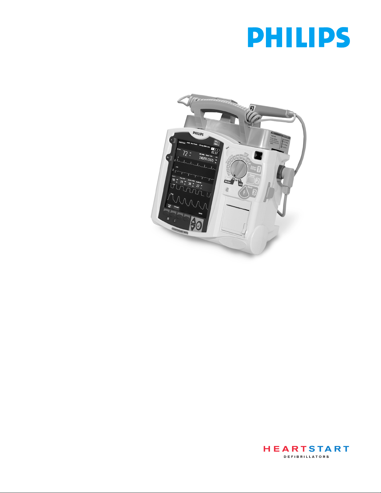
Front Panel
The front panel contains operational controls and indicators, as shown below.
Figure 1 Basic Orientation (Front)
Label Recess
Mark Event
button
Lead Select
button
Display
External Power Indicator
Synchronized Cardioversion
(Sync) Button
c
n
y
S
u
u
n
n
a
a
M
M
l
l
a
a
20
M
30
15
P
e
e
D
D
1-10
acer
onitor
A
D
120
b
b
150
i
i
100
f
f
70
50
n
O
O
n
O
ff
AED
Ready For Use (RFU)
Indicator
Therapy Knob
dult
ose
170
200
S
elect
E
nergy
1
C
harge
CHARGE button
SHOCK button
2
S
hock
3
Printer
(50 mm)
Printer Door
Printer Door
Latch
Print button
Speaker
Alarm Pause
button
Event Summary
button
Soft keys (4 total)
Navigation buttons
Menu Select button
The front panel also contains the printer and speaker.
Additional controls and indicators are on the paddles (if used) and batteries.
NOTE A palette of colored decals is included with your HeartStart MRx. These colored decals may be applied
to the label recesses located on the device handle to aid in identification. Use an indelible marker to
print identification information on the decal.
10
Page 21
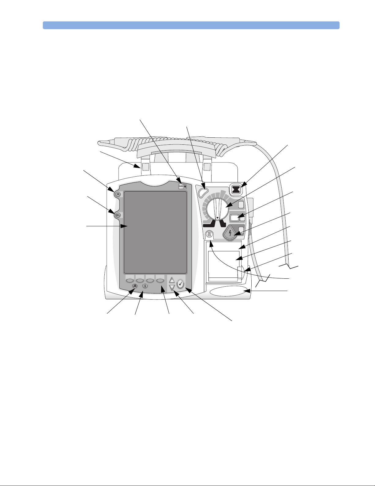
Basic Orientation 2 Getting Acquainted
Side Panels
The left side of the HeartStart MRx has ports for monitoring cables, including ECG, pulse oximetry
). The ECG port may be used to
2
Therapy Connector
CO2 Inlet Port
CO2 Outlet Port
(SpO2), noninvasive blood pressure (NBP), and carbon dioxide (CO
connect a 3-, 5-, or 10-lead patient cable. The ECG Out jack may be used to connect to an external
monitor. There is also a telephone jack (for future use).
The right side of the HeartStart MRx has a therapy port for paddles (external or internal) or
multifunction electrode pads. It also has a slot for a data card to transfer patient information.
Figure 2 Basic Orientation (Right/Left Sides)
2
O
C
r
c
i
M
1
2
™
m
a
e
r
t
s
o
G
C
E
NBP Port
ECG Port
SpO2 Port
Data Card
ECG Out (Sync)
Jack
RJ11 Telephone
G
C
E
Jack
11
Page 22
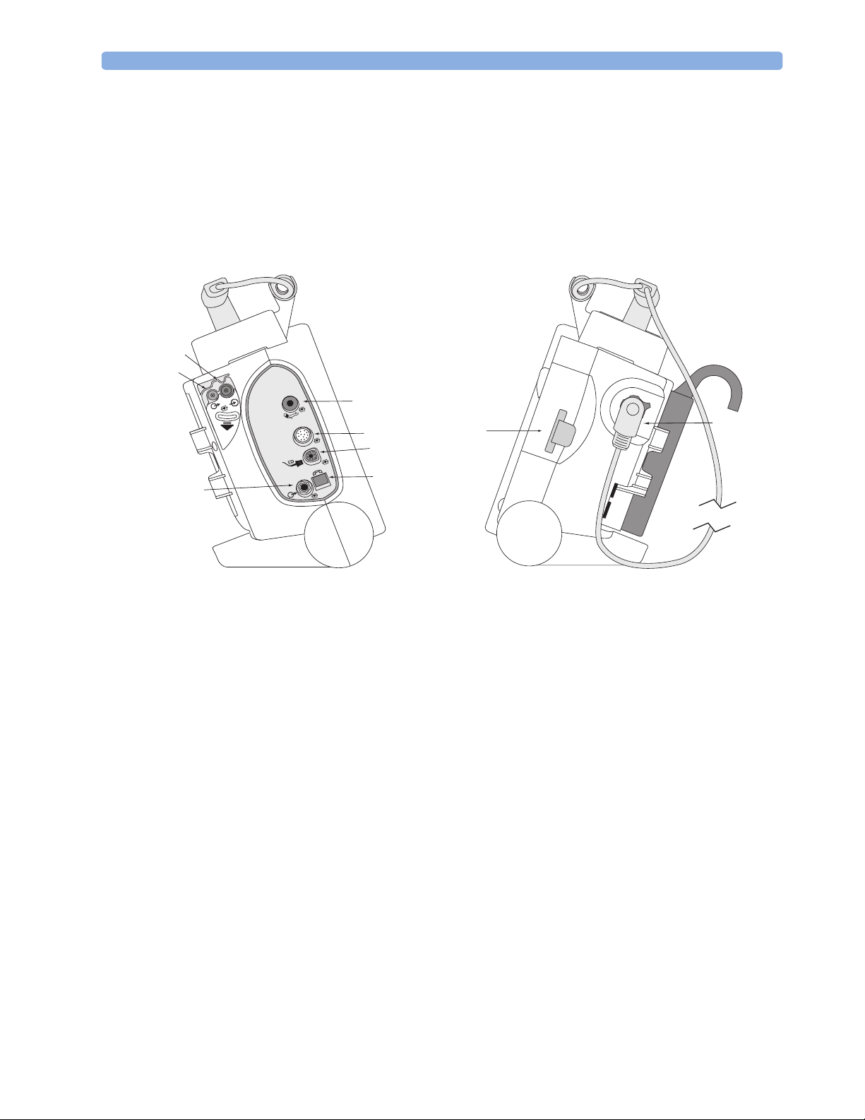
2 Getting Acquainted Basic Orientation
Top Panel
The top of the HeartStart MRx has a handle and basic operating instructions. If optional external
paddles are present, they reside on the top panel as shown.
Figure 3 Basic Orientation (Top - with Optional Paddles)
12
Page 23
Basic Orientation 2 Getting Acquainted
L
A
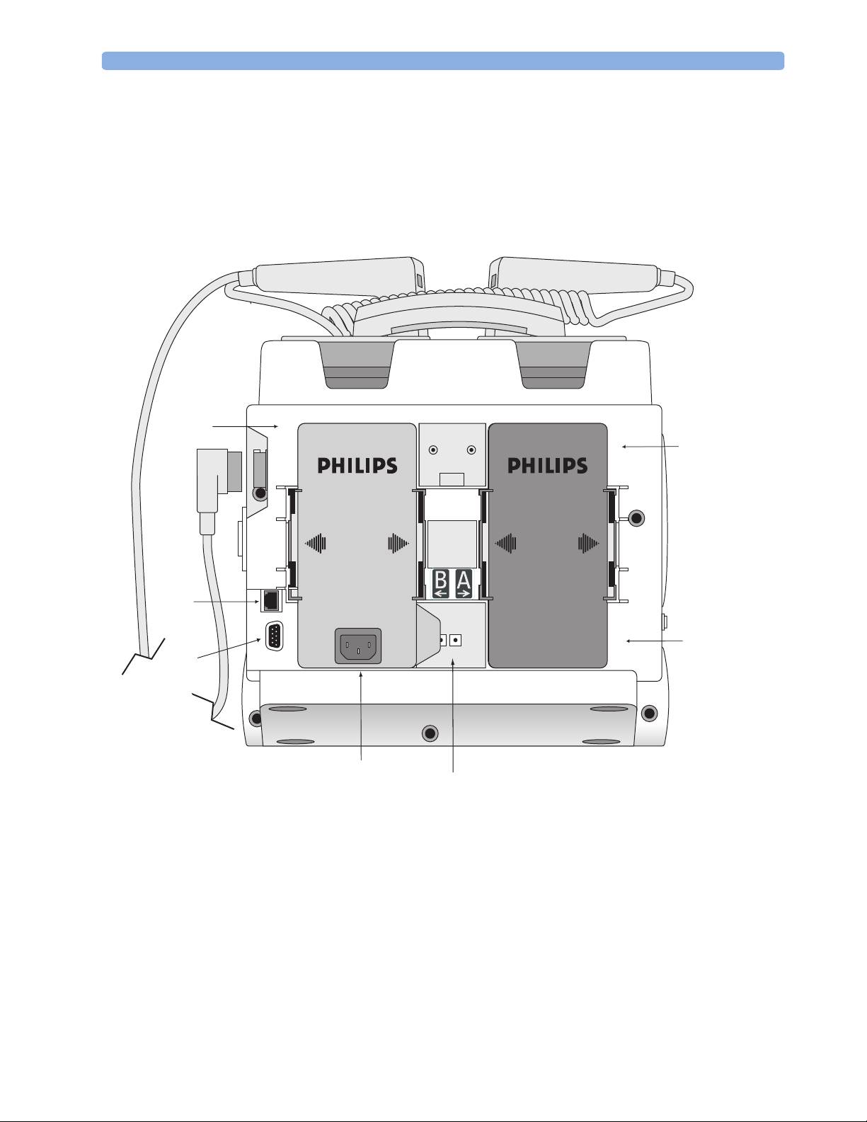
Back Panel
The back panel of the HeartStart MRx has two compartments for lithium ion batteries. Compartment
B may instead be used to connect an AC power module. Between the battery compartments is a DC
Power Input port.
The back panel also has an RS 232 serial port for 12-lead ECG transmission. The LAN port is for
factory use only.
Figure 4 Basic Orientation (Back)
Battery/AC
Compartment B
Battery
Compartment
AN Connection
Battery
RS 232 Serial Port
AC Power Module
DC Power Input
13
Page 24

2 Getting Acquainted M3538A Lithium Ion Battery
M3538A Lithium Ion Battery
The HeartStart MRx uses the M3538A Lithium Ion Battery. The battery has a fuel gauge with 5 LED
indicators, each representing a charge of approximately 20% of capacity. Press the fuel gauge button to
illuminate the fuel gauge.
NOTE A battery should be used as the primary power source, with AC/DC as a secondary source, if desired. If
an AC/DC power module is used as the only power source, the HeartStart MRx will take longer to
charge to the desired energy level.
Battery Capacity
A new, fully-charged M3538A battery, operating at room temperature 25oC(77oF), provides
approximately 5 hours of monitoring, with ECG, SpO
measured every 15 minutes, or at least 50 full-energy discharges.
Battery Life
Battery life depends on the frequency and duration of use. When properly cared for, the M3538A
Lithium Ion battery has a useful life of approximately 2 years. To optimize performance, a fully (or
nearly fully) discharged battery should be charged as soon as possible.
and CO2 monitored continuously and NBP
2
Operating Modes
The HeartStart MRx has four clinical modes of operation, each with a customized display view. The
modes are as follows:
Table 1 Operating Modes and Views
Mode of Operation Display View Description
Monitor Mode Monitoring View, or
12-Lead View
AED Mode AED View Used to analyze ECG and if necessary,
Manual Defib Mode Code View Used to perform asynchronous and
Pacer Mode Pacing View Used to perform demand or fixed mode
NOTE Upon returning to a clinical mode from a non-clinical mode such as Configuration or Data
Management, all settings are re-set to the device’s default values.
Used to monitor ECG, take an optional
12-lead ECG, and monitor optional
parameters such as SpO
perform semi-automatic external
defibrillation.
synchronous defibrillation (cardioversion).
pacing.
, EtCO2 and NBP.
2
14
Page 25
Display Views 2 Getting Acquainted
Password Security
Access to Manual Defib Mode and Pacer Mode may be password protected (for Version A.02 and later
devices) if enabled in Configuration. If enabled, you will be prompted to enter the password upon
moving the Therapy Knob to either the Pacer position or an energy selection. The password is entered
by using the Navigation buttons to select the password numbers and then selecting Done to complete
the entry. The Charge button and the [Start Pacing] soft key remain inactive until the
C
harge
2
password is entered.
WARNING Use of the Manual Therapy Security password requires the clinician to know and remember the
password, as defined in Configuration. Failure to enter the correct password will prevent the delivery of
manual defibrillation or pacing therapy. Prior to selecting this Configuration option, review this
potential risk with your Risk Manager.
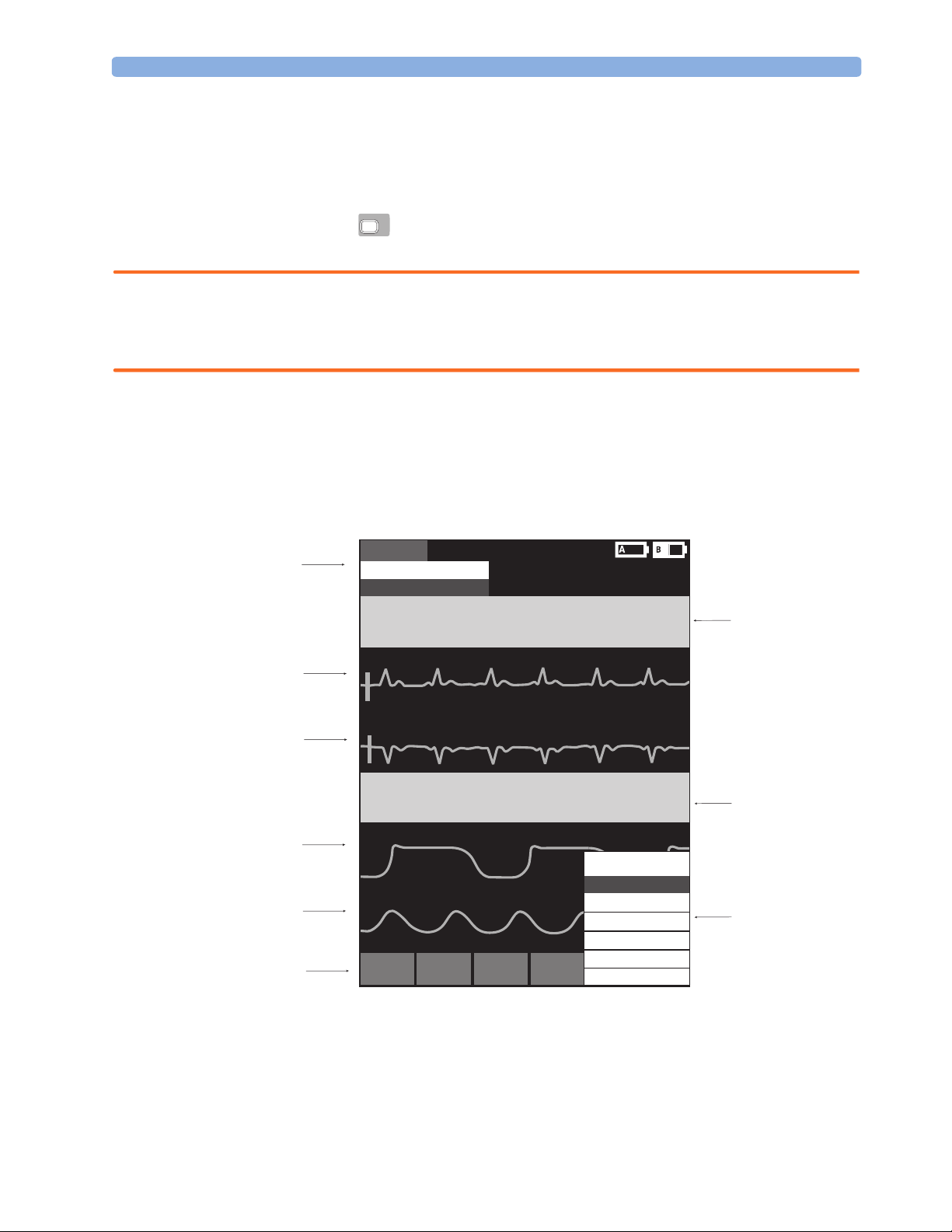
Display Views
The HeartStart MRx display layout is segmented as shown in Figure 5.
Figure 5 Display Layout
General Status
Area
Mark Event
Inops Area
ECG/HR alarms (R or Y)
HRHR
000000
Wav e
Sector 1
Wav e
Sector 2
Wav e
Sector 3
Wav e
Sector 4
Soft Keys
ECG Wave 1ECG Wave 1
Wave 2Wave 2
SpO2SpO2 etCO2
100
Wave 3
Wave 4
Softkey#1Softkey#2Softkey#3Softkey
100
90
120120
6060
Pulse
000
02 Mar 2003 10:52Adult Paced
HH:MM:SS
NBP q 30 10:40
000/000(000)
AwRR
000
#4
50
000
30
120
50
SYS
160
90
rhythm statusrhythm status
30
8
Main Menu
Volume
Waves
Measurements/Alarms
Patient Info
Other
Exit
Parameter
Block 1
Parameter
Block 2
Menu
Area
The content of these areas varies with the display view and the function being performed.
15
Page 26

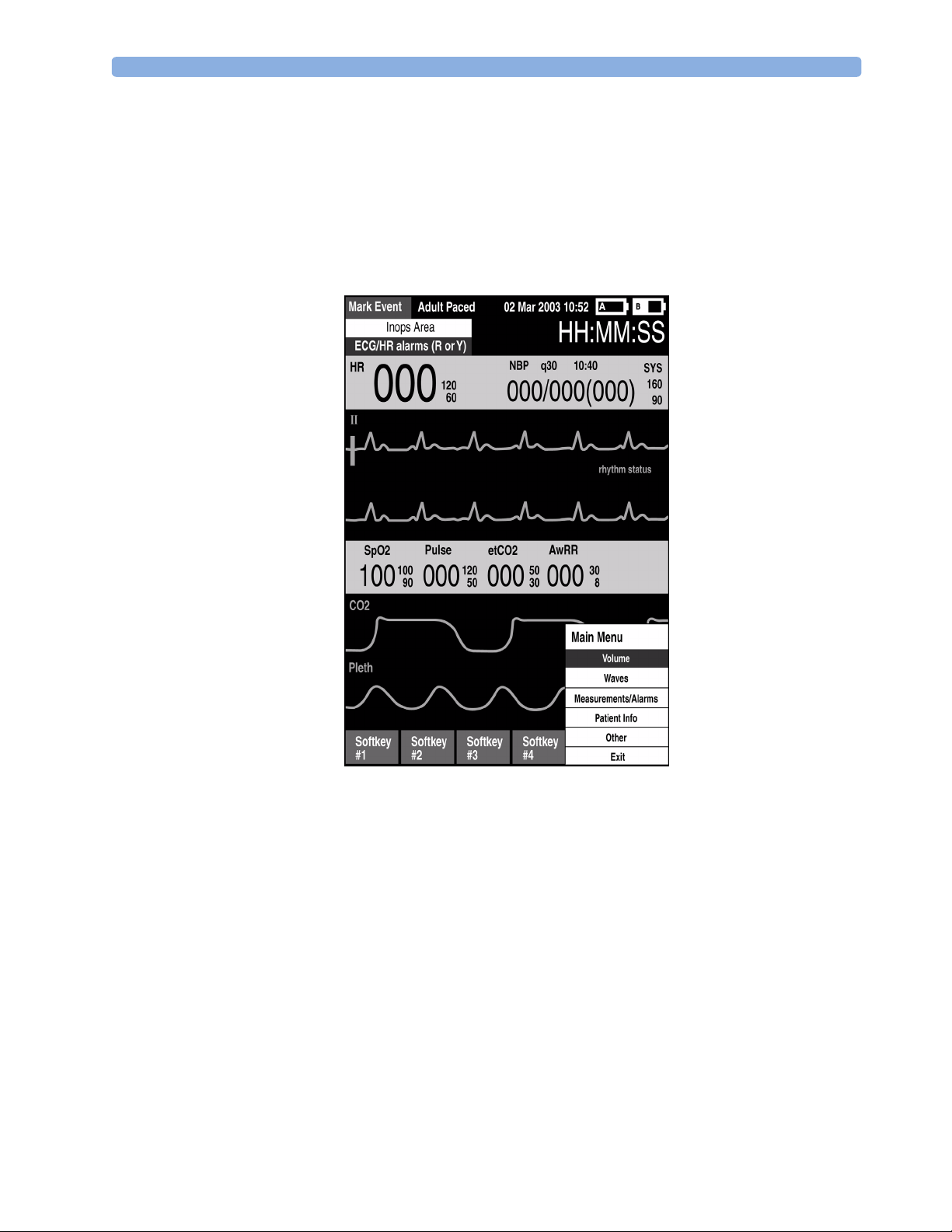
2 Getting Acquainted Display Views
y
General Status
The general status area of the display contains:
• Mark Event button label
• Patient information
Some modes of operation allow for the entry of patient information via a menu choice. If no
information is entered, the patient category is defaulted to Adult, unless configured otherwise, and
the pacing status is set to Non-Paced, unless the Paced status is set to Paced for an internally paced
patient, or the HeartStart MRx is pacing the patient. In Pacer Mode, Paced status is not displayed.
• Date and time
• Battery power indicators
Battery icons, labeled “A” and “B”, correspond with the battery compartments located at the back of
the HeartStart MRx. Each battery icon displays the current available battery power, ranging from
hollow (fully discharged) to full (fully charged), as shown in Figure 6. If the AC Power Module is
inserted in Compartment B, the no battery icon is displayed.
Figure 6 Battery Charge Level Indicators
AA
No Battery Empty Battery 25% Capacity 50% Capacity 75% Capacity 100% Capacit
A
AAA
• Inop statements
Inop statements appear in the top left of the display if equipment problems are detected.
• ECG/HR alarm status
Alarm messages communicate arrhythmia alarms, as well as overall alarm status (alarms off, alarms
paused).
•Event Timer
An Event Timer communicates the elapsed time since the device was turned on.
16
Page 27
Display Views 2 Getting Acquainted
Wave Sectors
The HeartStart MRx is configured to populate each wave sector with a predetermined waveform, when
powered on in Monitor, Manual Defib, or Pacer Mode. Figure 7 shows the default Waves
configuration choices. See “Configuration” on page 125 for more information.
A dashed line in a wave sector or an empty wave sector indicates that the waveform source is not
connected to the HeartStart MRx. Wave sectors may contain a variety of information, as appropriate to
the parameter, view, and task. Additionally, ECG wave sectors contain a calibration bar.
Figure 7 Default Waves Configuration
Wave Sector 1
Wave Sector 1 will only contain an ECG waveform. This is the waveform used by the arrhythmia,
heart rate derivation, and AED analysis algorithms. This waveform may be acquired through the
therapy port for pads/paddles or the monitoring port for 3-, 5-, or 10-lead electrodes. If the configured
source is not connected to the HeartStart MRx when turned on, the first valid ECG source is displayed
in Wave Sector 1. Once the configured source is available, it automatically populates Wave Sector 1.
Should the configured source then become invalid, a Leads Off condition is displayed. The HeartStart
MRx does not revert to the initial source of ECG.
NOTE If Pads are configured as the primary ECG source for Wave Sector 1, the ECG patient cable must be
connected to the MRx and to the monitoring electrodes on the patient in order to change the ECG
source to a Leads selection.
NOTE When monitoring using a 3-lead ECG set, the MRx displays only 1 ECG lead at a time.
17
Page 28

2 Getting Acquainted Display Views
Wave Sectors 2-4
Wave Sectors 2 through 4 are automatically populated when parameter sources (cables/tubing) are
connected to the HeartStart MRx. If the parameter source is the configured choice of a particular wave
sector, it is displayed in that wave sector. If you connect a parameter source that is not configured to be
displayed, it is displayed in the first empty wave sector. If you subsequently connect the configured
parameter source, it does not replace the current parameter, instead it populates the first available
empty wave sector.
Changing Displayed Waveforms
Wave Sector 1 has a dedicated Lead Select button to change the displayed lead/source. Waveforms
displayed in other wave sectors may be changed for the current patient through the display menu. See
“Display Menus” on page 19.
Parameter Blocks
Measurements for displayed waveforms and monitored parameters are provided in the parameter
blocks. Parameter Block 1 always contains the heart rate and HR alarm settings. The NBP schedule,
measurements, and alarm settings are also displayed in Parameter Block 1. Parameter Block 2 contains
measurements and alarm settings for SpO
measurement is labeled and displays the current value and the high and low alarm limit settings or the
(alarms off) icon. A “-?-” is displayed until a valid measurement can be obtained.
, Pulse, EtCO2 and Airway Respiration Rate (AwRR). Each
2
and EtCO2 measurements are activated when the associated parameter cable/tubing is
SpO
2
connected. When the SpO
and requests approval to turn off the measurement.
Parameter Alarm Messages are displayed in the space above each numeric value, replacing the
parameter label.
Soft Key Labels
The four soft key labels correspond to the soft key buttons located immediately below. These labels
change, as appropriate, according to the current display view and function. Soft key labels appearing as
grey text indicate that the soft key is inactive.
and EtCO2 cable/tubing is disconnected, a prompt message informs you
2
18
Page 29

Display Views 2 Getting Acquainted
Display Menus
Menus with controls and options specific to each function of the HeartStart MRx are easily accessible
through the Menu Select and Navigation buttons located on the front panel. Menus are used to adjust
volume, select waveforms for display, set alarms, schedule measurements, enter patient information,
perform the Operational Check, generate reports, and a variety of other tasks. Menus and submenus
are organized to allow you to conveniently make selections and enter information.
To display a menu, press the Menu Select button. Then use the up or down Navigation
buttons to scroll through the available choices until the desired selection is highlighted. To activate the
selection, press the Menu Select button. Press Exit to close the menu without activating a selection.
Figure 8 Sample Menu
HR/Arrhythmia
Relearn Rhythm
Alarms Off
HR Limits
VTACH Limits
Message Windows
Periodically, message windows appear on the display to provide additional status information, alert you
to an error or a potential problem, or direct you to take action. Remain alert to these messages. If a
response is required, as shown in Figure 9, use the Navigation and Menu buttons to highlight and
select the appropriate answer.
Figure 9 Sample Message Window
Exit
Configuration Not Saved - Exit Anyway?
Yes
No
19
Page 30

2 Getting Acquainted Controls
High Contrast Display
To optimize visibility of the MRx display when used in bright sunlight, Version A.02 and later devices
provide a High Contrast feature which may be enabled. In this view, the MRx display appears using a
yellow background with all other screen elements appearing in black or shades of gray. High Contrast
is enabled in Manual Defib, Pacer and Monitor Modes by pressing the Menu Select button and
selecting High Contrast On from the Main Menu.
NOTE The High Contrast feature does not display colors configured as red or blue, therefore, be sure your
device is configured correctly with the appropriate parameter color settings. See Table 16 on page 132
in Configuration.
Controls
The Therapy Knob is used to turn the HeartStart MRx on in the desired mode of operation. Operating
controls are organized by function, with general function buttons located along the left and bottom
sides of the display, defibrillation controls to the right of the display, and soft keys immediately below
the display. (See Figure 1.)
Therapy Knob
The Therapy Knob serves as the power switch for the HeartStart MRx. It can be set to:
•Off
• AED - to enable AED Mode for automated external defibrillation.
• Monitor - to enable Monitor Mode for 3- or 5-lead ECG monitoring, 12-lead ECG acquisition, or
monitoring of optional parameters such as SpO2, CO2, and NBP.
• Pacer - to enable Pacer Mode (optional) for demand or fixed mode pacing.
• Manual Defib - to enable Manual Defib Mode for asynchronous or synchronous defibrillation
(cardioversion) at the selected energy setting.
In Manual Defib Mode the defibrillation energy settings are labeled as 1-9, 10, 15, 20, 30, 50, 70, 100,
120, 150, 170, and 200 Joules. If your unit is equipped with the optional pacing function, the energy
settings are labeled as 1-10, 15, 20, 30, 50, 70, 100, 120, 150, 170, and 200 Joules.
20
Page 31

Controls 2 Getting Acquainted
General Function Buttons
The general function buttons control monitoring or non-critical resuscitation activities. They include:
Mark Event button - allows you to insert a time-stamped annotation in the Event Summary Report to
note events as they occur, including the administration of certain drugs. A Mark Event button label
appears at the top left corner of the display.
Lead Select button - changes the ECG lead in Wave Sector 1. Pressing this button cycles through the
available ECG waves, changing the displayed wave and label. The list of available ECG waves is based
on the current lead set and device configuration, and includes pads or paddles, if the corresponding
cable is connected to the device.
Alarm Pause button - The Alarm Pause button pauses all visual and audible physiological alarms and
audible inops for the configured time interval. At the end of the pause interval, each alarm returns to its
previous setting (On or Off). Pressing the Alarm Pause button during the pause interval also returns
alarms to their previous settings.
Print button - The Print button initiates a continuous print-out of the primary ECG and the
waveform displayed in Wave Sector 2, either real-time or with a 10-second delay, depending on your
configuration.
Event Summary button - The Event Summary button prints the current or most recent Event
Summary report.
Menu Select button - Pressing the Menu Select button either brings up the current menu or confirms
a menu selection.
Navigation buttons - The Navigation buttons display the current menu just as the Menu Select
button does. Additionally, within any menu or list, these buttons move to the next or previous item in
the list. They also increase or decrease numbers or values in a sequence. They may be held down to
accelerate through the available choices.
21
Page 32

2 Getting Acquainted Controls
Defibrillation Controls
The defibrillation controls are shown in Figure 10. They include the:
Therapy Knob - Enables AED or selects an energy for Manual Defib Mode defibrillation or
cardioversion.
Charge Button - Charges the defibrillator to the selected Manual Defib energy setting. Used only in
Manual Defib Mode. In AED Mode, the defibrillator charges automatically.
Shock Button - Delivers a shock through multifunction electrode pads or switchless internal paddles.
In AED mode a 150J shock is delivered. In Manual Defib Mode, the shock is delivered at the selected
Manual Defib energy setting.
NOTE When external paddles or switched internal paddles are used, once the HeartStart MRx is fully
charged, the shock is delivered by pressing the Shock button(s) on the paddles.
Sync Button - Toggles between synchronized energy delivery used during cardioversion and
asynchronous energy delivery used during defibrillation.
Figure 10 Defibrillation Controls
Soft Keys
c
Sync
Button
Therapy
Knob
n
y
S
b
b
i
i
100
f
f
e
e
70
D
D
l
l
a
a
50
u
u
n
n
a
a
30
M
M
20
15
1-10
acer
onitor
O
P
M
A
dult
D
ose
120
150
n
O
170
200
S
elect
E
nergy
1
C
harge
O
n
ff
AED
S
hock
3
2
Charge
Button
Shock
Button
The soft keys perform the function displayed as a label appearing immediately above on the display.
The labels (and, therefore, the function) change appropriately for the various modes of operation and
are described in the chapters which follow.
22
Page 33

Controls 2 Getting Acquainted
Indicators
The HeartStart MRx indicators provide a visual display of device status.
Ready For Use Indicator The Ready For Use (RFU) indicator is located on the upper, right corner of
the device. It indicates the status of the therapy delivery functions of the monitor/defibrillator using the
following definitions:
• A blinking black hourglass symbol indicates the shock, pacing, and ECG functions of the
device are ready for use. Sufficient battery power is available for device operation. Additionally, a
blinking black hourglass, together with the presence of external power (AC or DC), indicates that
installed battery(s) are being charged.
• A blinking red “X” and a periodic audio chirp indicate no battery is present or a low battery
condition. The device can be used, but its operation time is limited. If a battery is inserted and
charging, the audio chirp is not present.
• A solid red “X” and a periodic audio chirp indicate a failure has been detected that may
prevent the delivery of defibrillation therapy, pacing, or ECG acquisition. When turned on, the
device displays inop messages for the failures detected.
• A solid red “X” without periodic audio chirps indicates either there is no power available, or
the device cannot power on. If, after power is supplied, the indicator reverts to the blinking black
hourglass symbol, the device is once again ready for use.
NOTE The RFU indicator may briefly display a solid red "X" when initially turning the device on, when
switching between clinical and non-clinical operating modes, and at the start of any automated test.
External Power Indicator The external power indicator is located above the display. It is green if
power is being provided by an external AC or DC power source. See Figure 11.
Figure 11 External Power Indicator
NOTE The external power indicator will momentarily go out when charging for defibrillation with a charged
battery installed. This is normal operation, as the device is switching its power source to the battery for
a faster charge time.
23
Page 34

2 Getting Acquainted Responding to Alarms
Responding to Alarms
When an alarm condition occurs and an alarm is indicated, visually and audibly, there are several ways
to respond. Initially:
1 Attend to the patient.
2 Identify the alarm(s) indicated.
3 Silence the alarm(s). When an alarm is announced, the audio pause label (see Figure12) is
presented above the Navigation and Menu Select buttons. Pressing any of these buttons will silence
the alarm audio while you are attending to the patient.
Figure 12 Audio Pause Label
AUDIO PAUSE
For devices with
serial numbers US001XXXXX
Then:
4 Address the alarm condition on the HeartStart MRx. The menu shown in Figure 13 appears.
Figure 13 Sample Alarm Response Menu
AUDIO PAUSE
For devices with
serial numbers US002XXXXX
SpO2 Alarm
Alarms Off
Acknowledge
New Limits
Alarms Off Turns the monitoring parameter’s alarms off. The alarm message is no longer displayed,
and the icon appears next to the parameter value.
Acknowledge The alarm message continues to display and, if after 2 minutes the alarm condition still
exists, the alarm audio and response sequence occurs again.
New Limits Adjust the parameter limits accordingly.
WARNING Although the Alarm Pause button can be used when responding to alarms, the response procedures
described above are recommended.
NOTE The information above does not pertain to Heart Rate or Arrhythmia Alarms. For information about
responding to these alarms, see “Responding to HR and Arrhythmia Alarms” on page 52.
24
Page 35

Entering Patient Information 2 Getting Acquainted
Entering Patient Information
Patient information may be entered for the following:
•Name
•ID
• Patient Category
•Age
•Sex
•Paced
Information is entered using the Patient Info menu. Patient Name is entered using 2 alphabetical lists,
one to enter the last name, followed by another to enter the first name. When each name is complete,
select Done or Cancel to close the patient name menu without saving.
Continued Use
Once a patient event is started, the Continued Use feature is activated. This feature facilitates
continued treatment of the same patient by retaining the current settings and the patient record when
the HeartStart MRx is turned off for less than 10 seconds, for instance when switching between AED
and Manual Defib Modes or when the Therapy Knob is inadvertently moved to Off. When turned on
within the 10 second time period, the HeartStart MRx retains the most recent settings, including:
• Alarm settings
• Wave Sector settings
•Event Timer
• QRS, alarm tone, and voice prompt volumes
•ECG gain
• Pacing settings
• Patient record in the Event Summary Report; new data is appended to the record.
The Sync feature remains active if the HeartStart MRx is turned off for less than 10 seconds. However,
Sync is disabled when AED Mode is activated, and must be turned on upon returning to Manual
Defib Mode.
NOTE The Continued Use feature will not function if all sources of power (battery and external AC/DC
power modules) are removed from the device, even briefly.
25
Page 36

2 Getting Acquainted Return to Owner
Return to Owner
The Return to Owner feature is available in Version A.02 and later devices and allows the owner of the
HeartStart MRx to enable a specified loan period, after which the borrower of the MRx will be
reminded to return the device to its owner as identified on the display. The feature is password
protected in Configuration and enabled through the Other Menu, where the owner can activate,
deactivate, and specify the length of the loan period.
NOTE Monitoring and defibrillation functions are suspended while the Return to Owner set-up screen is
displayed.
NOTE The appearance of the loan expiration message does not disable monitoring and defibrillation
functionality.
To enable the Return to Owner feature:
1 Press the Menu Select button.
2 Select Other from the menu and press the Menu Select button.
3 Select Return To Owner and press the Menu Select button.
4 Press the [Activate] soft key.
5 Enter the number of days in the loan period and press the Menu Select button.
6 Press the [Exit Return-To] soft key.
To disable the Return to Owner feature:
1 Press the Menu Select button.
2 Select Other from. the menu and press the Menu Select button.
3 Select Return To Owner and press the Menu Select button.
4 Press the [Deactivate] soft key.
5 Enter the password and press the Menu Select button.
6 Press the [Exit Return-To] soft key.
26
Page 37

3
3Setting Up
This chapter provides the basic set-up information you need to prepare your device for operation and
to connect the optional monitoring accessories to your HeartStart MRx.
NOTE If your HeartStart MRx does not have optional SpO
functionality, or optional accessory pouches, disregard these features and the related information
described in this chapter.
Before using the HeartStart MRx, review the configuration settings of your device. Confirm and
update the settings as appropriate.
, CO2, NBP, Pacing, or 12-lead ECG
2
Attaching the Carrying Case and Accessory Pouches
The HeartStart MRx accessory pouches are designed to hold your essential monitoring and
defibrillation accessories. Follow the procedures below for assembly and recommended accessory
placement.
1 Disconnect all external power and remove all batteries.
2 Lower the device into the sleeve of the carry case. The rear base of the device fits in the sleeve
socket.
Paddle Tray
a. If paddles are connected, disconnect them from the Therapy port and remove them from the
paddle tray.
b. Remove the 4 T-15 screws from the tray plates.
c. Gently lift the paddle tray up, leaving all wires connected.
Handle Only
a. Remove the handle cover by pushing in on either side of the handle cover and lifting up.
b. Remove the 2 T-15 screws.
c. Remove the handle.
d. Gently lift the cap plate up.
27
Page 38

3 Setting Up Attaching the Carrying Case and Accessory Pouches
3
Fold the two sleeve flaps over the top of the device, positioning them so that the screw holes are
exposed.
4 Replace the paddle tray or cap plate, as appropriate, so that the molded openings fit over the sleeve
flaps.
5 Secure the front and rear cinch straps using the metal rings provided.
6 Perform an Operational Check as described in, “Maintenance” on page 151.
7 Attach the side pouches using the snaps located inside the pouch pockets.
Figure 14 Accessory Pouch Assembly and Accessory Placement
28
Page 39

Storing Accessories 3Setting Up
(
(
(
(
(
(
(
(
(
(
(
(
(
(
(
(
(
(
(
(
(
(
(
(
(
(
(
(((
(
(
(
(
(
(
(
(
(
(
(
(
(
(
(
(
(
(
(
(
(
(
(
(
(
(
(
(
(
(
(
(
(
(
(
(
(
(
(
(
(
(
(
(
(
(
(
(
(
(
(
(
(
(
(
(
(
(
(
(
(((
(
(
(
(
(
(
(
(
(
(
(
(
(
(
(
(
(
(
(
(
(
(
(
(
(
(
(
(
(
(
(
(
(
(
(
(
(
(
(
(
(
(
(
(
(
(
(
(
(
(
(
(
(
(
(
(
(
(
(
(
(
(
(
(
(
(
(
(
(
(
(
(
(
(
(
(
(
(
(
(
(
(
(
(
(
(
(
(
(
(
(
(
(
(
(((
(
(
(
(
(
(
(
(
(
(
(
(
Storing Accessories
1 Store parameter cabling and accessories as shown below.
2 Route the ECG cabling underneath the paper storage cylinder.
29
Page 40

3 Setting Up Storing Accessories
(
(
(
(
(
(
(
(
(
(
(
(
((
(
(
(
(
(
(
(
(
(
(
(
(
(
(
(
(
((
(
(
(
(
(
(
(
(
3 Attach the Therapy cable and route it through cable fastener loop, securing the cable just below the
strain relief.
4 Attach the rear pouch using the buckles provided.
NOTE Depressions are provided on the inside of the rear pouch should you wish to make a cut-out to
accommodate external power.
(
(
(
(
(
(
(
(
(
(
(
(
(
(
(
(
(
(
(
(
(
(
(
(
(
(
(
(
(
(
(
(
(
(
(
(
(
(
(
(
(
(
(
(
(
(
(
(
(
(
(
(
(
(
(
(
(
(
(
(
(
(
(
(
(
(
(
(
(
(
(
(
(
(
(
WARNING When using the carry bag to transport the HeartStart MRx, it is important to position it with the
display facing away from the body. If not, the Therapy Knob may be bumped and inadvertently moved
from its current position.
30
Page 41

Connecting the ECG Cable 3Setting Up
Connecting the ECG Cable
To connect a 3-, 5- or 10-lead cable:
1 Align the ECG cable with the white ECG port, as shown in Figure 15. The white key marker on
the ECG cable faces the top of the device.
2 Push the ECG cable firmly into the ECG port, until the white portion of the cable connector is no
longer visible.
Figure 15 Connecting the ECG Patient Cable
2
CO
1
2
ECG
ECG
31
Page 42

3 Setting Up Connecting the SpO2 Cable
Connecting the SpO2 Cable
To connect the SpO2 cable:
1 Hold the cable connector with the flat side facing front, as shown in Figure 16.
2 Insert the cable into the blue SpO
the cable connector is no longer visible.
Figure 16 Connecting the SpO
port on the HeartStart MRx and push until the blue portion of
2
Cable
2
O
2
C
1
2
G
C
E
G
C
E
32
Page 43

Connecting the NBP Interconnect Tubing 3Setting Up
Connecting the NBP Interconnect Tubing
To connect the NBP Interconnect Tubing:
1 Insert the NBP Interconnect Tubing into the red NBP port as shown in Figure 17.
2 Attach the NBP Interconnect Tubing fitting to the NBP cuff.
Figure 17 Connecting NBP Interconnect Tubing / NBP Cuff
2
CO
1
2
ECG
ECG
33
Page 44

3 Setting Up Connecting the CO2 Nasal FilterLine
®
Connecting the CO2 Nasal FilterLine
To connect the CO2 Nasal FilterLine®:
1 Using the end of the nasal FilterLine fitting, slide the CO
2 Insert the fitting into the CO
Inlet port as shown in Figure 18.
2
3 Turn the fitting clockwise into place.
Figure 18 Connecting the CO
Nasal FilterLine
2
2
CO
1
2
ECG
ECG
compartment door down.
2
®
®
34
Page 45

Connecting the Therapy Cable 3Setting Up
Connecting the Therapy Cable
To connect the Therapy cable:
1 Align the white pointer on the cable with the white arrow on the green Therapy port as shown in
Figure 19.
2 Insert the cable into the green Therapy port. Push until you hear it click into place.
Figure 19 Connecting the Therapy Cable
35
Page 46

3 Setting Up Installing Paper
O
er
2
O
er
2
Installing Paper
50mm Printer
To install printer paper:
1 Open the printer door by pushing on the latch as shown in Figure 20.
2 If there is an empty or low paper roll in the printer, pull up on the roll to remove it.
3 Place a new roll of printer paper into the paper well, positioning the roll so that the end of the roll
is on the bottom and the grid faces up.
4 Pull the end of the paper out past the paper roller.
5 Close the printer door.
Figure 20 Installing Paper(50mm)
M
onitor
n
O
O
ff
n
A
E
D
S
ho
c
k
3
M
onitor
n
O
O
ff
n
A
E
D
S
ho
c
k
3
36
Page 47

Installing Paper 3Setting Up
2
3
Shock
AED
Monitor
Off
On
On
2
3
Shock
AED
Monitor
Off
On
On
75mm Printer
To install printer paper:
1 Open the printer door by pushing on the latch as shown in Figure 21.
2 If there is an empty or low paper roll in the printer, pull up on the tab holding the paper roll to
remove it.
3 Place a new roll of printer paper into the paper well, positioning the roll as shown in Figure 21.
4 Pull the end of the paper out past the paper roller.
5 Close the printer door.
Figure 21 Installing Paper (75mm)
37
Page 48

3 Setting Up Installing Batteries
Installing Batteries
To install the batteries:
1 Align the M3538A Lithium Ion battery in a battery compartment.
2 Insert the battery, and press until you hear it click into place. Ensure that the latches located on
both sides of the battery are engaged fully.
Figure 22 Installing batteries
Charging Batteries
Charge batteries fully upon receipt and prior to use. Be sure to familiarize yourself with the battery
maintenance procedures discussed in “Maintenance” on page 151.
Battery Safety
Review the Application Note, M3538A Lithium Ion Battery - Characteristics and Care, provided with
your HeartStart MRx. Additionally, read the battery related warnings in “Specifications and Safety” on
page 213, prior to using the M3538A Lithium Ion Battery.
38
Page 49

Installing the AC Power Module 3Setting Up
Installing the AC Power Module
If not presently installed in your device, insert the M3539A AC power module as follows:
1 Align the M3539A AC power module in Compartment B.
2 Insert the AC power module, and press until you hear it click into place. Ensure that the latched
located on both sides of the AC power module are engaged fully.
3 Insert the power cord into the AC power receptacle.
4 Plug into an AC power outlet.
5 Check that the External Power indicator on the front panel is illuminated.
Figure 23 Installing the AC Power Module
39
Page 50

3 Setting Up Installing the Data Card
S
el
Installing the Data Card
If not presently installed in your device, install the data card as follows:
1 Insert the data card in the data card tray, sliding it under the tray clip.
2 With the front of the tray facing forward, insert the tray fully into the data card slot located on the
right side of the HeartStart MRx.
Figure 24 Installing the Data Card/Tray
e
c
t
E
nergy
1
C
harge
O
n
O
O
ff
n
r
A
E
D
2
S
ho
c
k
3
CAUTION Even if a data card is not used, the data card tray should always be installed to protect the device from
the ingress of liquids or solids.
40
Page 51

This chapter describes the basic ECG and arrhythmia monitoring functions of the HeartStart MRx
monitor/defibrillator. For specific information related to taking a 12-Lead ECG, refer to Chapter 11,
“12-Lead ECG” on page 105.
Overview
The HeartStart MRx can be used for ECG and arrhythmia monitoring. The monitoring function
allows you to monitor through:
• multifunction electrode pads, or
4
4ECG and Arrhythmia
Monitoring
• 3-, 5-, or 10-lead ECG sets.
If both pads and monitoring electrodes are connected, monitoring allows you to select a lead from the
3-, 5- or 10-lead ECG source, or to monitor through the pads.
Configurable heart rate and arrhythmia alarms clearly communicate patient status, both audibly and
visually.
41
Page 52

4 ECG and Arrhythmia Monitoring Monitoring View
Monitoring View
Monitoring View appears on the display when the Therapy Knob is in the Monitor position. Figure 25
shows the information displayed in Monitoring View.
Figure 25 Monitoring View
42
Monitoring View can display up to four ECG waves. Numeric values for heart rate and all other
available parameters are displayed, as well as any active alarm settings.
Page 53

Preparing to Monitor ECG 4 ECG and Arrhythmia Monitoring
There are two separate sources of ECG, the ECG leads connection and the Pads/Paddles connection.
Leads/pads are displayed according to your device’s configuration. Typically, Lead II is configured as
the primary ECG lead source, displayed in Wave Sector 1. You may change this during use with the
Lead Select button. You can also configure the HeartStart MRx to display up to 3 additional leads (or
pads/paddles) when turned on (see Chapter 13, “Configuration” on page 125). The leads displayed
may be changed during use through the Waves menu item.
Monitoring View displays the first valid source of ECG acquired in Wave Sector 1. For example, if
your HeartStart MRx has Lead II configured to display in Wave Sector 1, but pads are attached to the
patient and connected to the defibrillator before a valid ECG can be obtained from the monitoring
electrodes, then Pads will be displayed in Wave Sector 1. However, Lead II will take its place as soon as
it is acquired.
NOTE The ECG lead source appearing in Wave Sector 1 is used to determine heart rate and monitor
arrhythmia.
Preparing to Monitor ECG
To prepare for monitoring ECG, perform the following steps.
If monitoring via electrodes:
1 Prepare the patient’s skin prior to applying monitoring electrodes. Skin is a poor conductor of
electricity, so skin preparation is important in achieving good electrode-to-skin contact.
– Identify the appropriate electrode sites (See Figures 27 and 28.)
– If necessary, clip hair at the electrode sites (or shave sites if needed).
– Wash sites thoroughly with soap and water. (Never use ether or pure alcohol, as this increases
skin resistance.)
– Dry the electrode sites briskly to increase capillary blood flow in the tissues and to remove oil
and skin cells.
2 Attach the snaps to the electrodes before placing them on the patient.
3 Apply the electrodes by peeling them, one at a time, from the protective backing and sticking them
firmly to the patient’s skin. Refer to Figures 27 and 28 for proper electrode placement. Press
around the entire edge of each electrode to ensure they are secure. Make sure the lead wires do not
pull on the electrodes.
WARNING Be sure that the electrodes do not come in contact with other conductive materials, especially when
connecting or disconnecting the electrodes to/from the patient.
43
Page 54

4 ECG and Arrhythmia Monitoring Preparing to Monitor ECG
4
If not preconnected, connect the ECG patient cable.
– Align the keyed patient cable connector with the ECG port on the Measurement module, as
shown in Figure 26.
– Push the patient cable firmly into the ECG port until the white portion is no longer visible.
Figure 26 ECG Cable Connection
2
CO
1
2
ECG
ECG
If monitoring via multifunction electrode pads:
1 If not preconnected, connect the pads cable to the HeartStart MRx. See Figure 34 on page 57.
2 Connect the pads to the pads cable. See Figure 35 on page 58.
3 Apply the pads as directed on the package.
NOTE If monitoring for extended periods of time, monitoring electrodes and multifunction electrode pads
may need to be changed periodically. Refer to the manufacturer’s documentation for how often to
replace the monitoring electrodes or pads.
44
Page 55

Electrode Placement 4 ECG and Arrhythmia Monitoring
Electrode Placement
Figure 27 shows the typical electrode placement for a 3-lead ECG set.
Figure 27 3-lead Placement
RA/R placement: directly below the clavicle and
RA/R
(White/
Red)
–
–
II
+
I
LA/L
–
(Black/
Yellow)
near the right shoulder
LA/L placement: directly below the clavicle and
near the left shoulder
III
LL/F placement: on the left lower abdomen
LL/F
+
(Red/
+
Green)
Figure 28 shows the typical electrode placement for a 5-lead ECG set.
Figure 28 5-lead Placement
RA/R placement:directly below the clavicle and near
the right shoulder
LA/L placement: directly below the clavicle and near
the left shoulder
RL/N placement: on the right lower abdomen
RA/R
–
(White/
Red)
V/C
(Brown/
White)
aVL
+
–
LA/L
(Black/
Yellow)
I
–
aVR
III
II
aVF
LL/F placement: on the left lower abdomen
RL/N
(Green/
Black)
+
LL/F
+
(Red/
Green)
V/C placement: on the chest; the position depends on
your required lead selection. See Figure 29.
45
Page 56

4 ECG and Arrhythmia Monitoring Electrode Placement
y
The V/C lead may be placed in any of the precordial lead positions as shown in Figure 29 (V1/C1
through V6/C6).
Figure 29 V/C Electrode Placement
V1/C1 placement:fourth intercostal space at
right sternal margin.
V2/C2 placement: fourth intercostal space at
left sternal margin.
1
2
3
4
5
6
V3/C3 placement: midway between V2 and
V4.
V4/C4 placement: fifth intercostal space at
left midclavicular line.
V5/C5 placement: same level as V4 on
anterior axillary line.
V6/C6 placement: same level as V4 at left mid
line.
axillar
For accurate V/C lead placement and measurement, it is important to locate the fourth intercostal
space, as follows:
1 Locate the second intercostal space by first palpating the Angle of Lewis (the small bony
protuberance where the body of the sternum joins the manubrium). This rise in the sternum is
where the second rib is attached, and the space just below this is the second intercostal space.
2 Palpate and count down the chest until you locate the fourth intercostal space.
Figure 30 shows the typical electrode placement for a 10-lead ECG set.
Figure 30 10-lead Placement
Conventional 12-Lead ECG In conventional 12-Lead ECG
using 10 electrodes, an electrode is placed on the right arm,
left arm, right leg, and left leg. Six V/C electrodes are placed
on the chest as shown in Figure 30. The right leg electrode is
the reference electrode.
46
Page 57

Lead Selection 4 ECG and Arrhythmia Monitoring
Lead Selection
It is important to select a suitable lead for monitoring so that a QRS complex can be accurately
detected. The guidelines for lead selection are as follows:
For non-paced patients:
• QRS complex should be tall and narrow (recommended amplitude > 0.5mV).
• R-wave should be above or below the baseline (but not biphasic).
• P-wave should be smaller than 1/5 R-wave height.
• T-wave should be smaller than 1/3 R-wave height.
NOTE To prevent detection of P-waves or baselines noises as QRS complexes, the minimum detection level
for QRS complexes is set at 0.15 mV, according to AAMI-EC 13 specifications. If the ECG signal is
too weak, you may get false alarms for asystole.
For paced patients with internal/transvenous pacemakers, in addition to the above, the pace pulse
should be:
• not wider than the normal QRS complex.
• large enough to be detected (half the height of the QRS complex), with no re-polarization artifact.
NOTE Adjusting the ECG wave size on the display does not affect the ECG signal which is used for
arrhythmia analysis.
Lead Choices
Available monitoring leads vary depending upon what type of ECG cable is connected to your
HeartStart MRx and its configuration. Table 2 shows the choice of leads available for 3-, 5-, and 10lead ECG sets.
Table 2 Lead Choices
If you are using: These leads are available:
a 3-lead ECG set I, II, III
a 5-lead ECG set I, II, III, aVR, aVL, aVF, V/C
a 10-lead ECG set I, II, III, aVR, aVL, aVF,
V1/C1, V2/C2, V3/C3, V4/C4, V5/C5, V6/C6
47
Page 58

4 ECG and Arrhythmia Monitoring Arrhythmia Monitoring
Selecting the Lead
The ECG lead for Wave Sector 1 is selected through the Lead Select button or through the Waves
menu. The ECG lead for Wave Sectors 2-4 is selected through the Wa ve s menu, as follows:
1 Press the Menu Select button.
2 Using the Navigation buttons, select the Wav es menu and press the Menu Select button.
3 Select the Wave Sector and press the Menu Select button.
4 Select the desired lead and press the Menu Select button.
5 If needed, use the Navigation buttons to adjust the ECG wave size (gain) and press the Menu
Select button.
Figure 31 Waves Menu
Main Menu
Volume
Waves
Measurements/Alarms
Patient Info
Other
Exit
Waves
Wave 1
Wave 2
Wave 3
Wave 4
Exit
Wave 1
Paddles
I
II
III
aVR
aVL
aVF
V
I
S
iz
e
x
x
x
x
1/2
x
1/4
A
uto
Arrhythmia Monitoring
The HeartStart MRx uses the ST/AR Basic Arrhythmia Algorithm. Arrhythmia analysis provides
information on your patient’s condition, including heart rate and arrhythmia alarms. The HeartStart
MRx uses the ECG lead appearing in Wave Sector 1 for single-lead arrhythmia analysis.
NOTE Because the ST/AR Basic Arrhythmia Algorithm is the HeartStart MRx’s cardiotach source and is
needed to generate heart rate and heart rate alarms, the algorithm can never be disabled. However, if
desired, arrhythmia and heart rate alarms can be turned off.
During arrhythmia analysis, the monitoring function continuously:
• optimizes ECG signal quality to facilitate arrhythmia analysis. The ECG signal is continuously
filtered to remove baseline wander, muscle artifact, and signal irregularities. Also, if the Patient Paced
status is set to Yes, pace pulses are filtered out to avoid processing them as QRS beats.
4
2
1
48
• measures signal features such as R-wave height, width and timing.
• creates beat templates and classifies beats to aid in rhythm analysis and alarm detection.
• examines the ECG signal for ventricular fibrillation, asystole, and noise.
Page 59

Arrhythmia Monitoring 4 ECG and Arrhythmia Monitoring
Aberrantly-Conducted Beats
As P-waves are not analyzed, it is difficult and sometimes impossible for the algorithm to distinguish
between an aberrantly-conducted supraventricular beat and a ventricular beat. If the aberrant beat
resembles a ventricular beat, it is classified as a ventricular beat. You should always select a lead where
the aberrantly-conducted beats have an R-wave that is as narrow as possible to minimize incorrect
classifications.
Intermittent Bundle Branch Block
Bundle branch and other fascicular blocks create a challenge for the arrhythmia algorithm. If the QRS
complex changes considerably from the learned normal due to a bundle branch block, the blocked beat
may be incorrectly identified as ventricular, and may cause false PVC alarms. You should always select
a lead where the bundle branch block beats have an R-wave that is as narrow as possible to minimize
incorrect classifications.
NOTE For more information on arrhythmia analysis, refer to the Application Note, “Arrhythmia Monitoring
Algorithm” available on the web at www.medical.philips.com/goto/productdocumentation.
49
Page 60

4 ECG and Arrhythmia Monitoring Heart Rate and Arrhythmia Alarms
Heart Rate and Arrhythmia Alarms
The HeartStart MRx detects arrhythmia alarm conditions by comparing ECG data to a set of predefined criteria. An alarm can be triggered by a rate exceeding a threshold (for example HR > XX), an
abnormal rhythm (for example, Ventricular Tachycardia), or an ectopic event (for example, PVC >
limit).
HR/Arrhythmia Alarms can be generated for the conditions shown in Tables 3 and 4. Once generated,
they appear as alarm messages in the alarm status area of the display located just above the HR
numeric. The notification of an alarm is indicated by both an audible and visual alert signal.
The presence of multiple alarm conditions is quite possible. Announcing all of the detected alarms
would cause confusion and a less serious condition might hide a more serious condition. For this
reason, alarms are prioritized and categorized so that the most serious or highest priority alarm
condition is the one announced.
Arrhythmia Alarm Latching
Arrhythmia Alarms are categorized as “latching” or “non-latching” alarms. Latching alarms are
announced and remain present, regardless of whether the alarm condition still exists, until they are
either acknowledged or a higher priority alarm condition occurs. Indications for non-latching alarms
are automatically removed when their alarm condition no longer exists.
Latching and non-latching alarms are categorized in Tables 3 and 4.
Table 3 HR/Arrhythmia Red Alarms
Alarm Message Condition Indicator Latching/
Asystole No detectable beats for four
seconds in the absence of
Vfib
VFIB/VTACH A fibrillatory wave detected
for four seconds
VTACH Consecutive PVCs and HR
exceed defined limits
Extreme Brady 10 bpm below HR Low
limit, capped at 30 bpm
Extreme Tachy 20 bpm above HR High
limit capped at 200 bpm
(adult) or 240 bpm (pedi)
Red alarm message,
alarm tone
Red alarm message,
alarm tone
Red alarm message,
alarm tone
Red alarm message,
alarm tone
Red alarm message,
alarm tone
Non-Latching
Latching
Latching
Latching
Latching
Latching
50
Page 61

Heart Rate and Arrhythmia Alarms 4 ECG and Arrhythmia Monitoring
Table 4 HR/Arrhythmia Yellow Alarms
Alarm Message Condition Indication Latching/
Non-Latching
HR High The HR exceeds the configured
HR high limit
HR Low The HR is below the configured
HR low limit
PVC/min High
(value > limit)
Pacer Not Capture No QRS following a pacer pulse Yellow alarm
Pacer Not Pacing No QRS or pacer pulse detected Yellow alarm
NOTE Pacer Alarm Messages are associated with internal/transvenous pacemakers only
The number of detected PVCs in
a minute exceeds the limit of
15(adult/pedi.)
Yellow alarm
message, alarm tone
Yellow alarm
message, alarm tone
Yellow alarm
message, alarm tone
message, alarm tone
message, alarm tone
INOP Messages
INOP messages communicate conditions that prevent the device from monitoring or analyzing the
ECG. INOP messages are displayed just above the HR/Arrhythmia alarm status area. If multiple
INOP conditions exist, the associated INOP messages will cycle through, alternating every 2 seconds.
Table 5 ECG INOPS
Alarm Message Condition Indication
Non-Latching
Non-Latching
Non-Latching
Latching
Latching
Cannot Analyze ECG Cannot reliably monitor the ECG in
Wave Se c to r 1.
ECG Cable Failure During the Operational Check, a short
has been detected between a lead wire
and ground
Leads Off An electrode used for Wave Sector 1
may be off or not attached securely.
Pads /Paddles Off The multifunction electrode pads used
as the source for the Wave Sector 1 may
be off or not attached securely.
ECG Unplugged The primary ECG is derived from leads
and the ECG cable is not connected.
ECG Equip Malfunction A malfunction has occurred in the
ECG hardware.
Pads/Paddles Cable
Failure
Pads ECG Equip
Malfunction
During the Operational Check, a
failure was detected in the pads or
paddles cable during the pads/paddles
ECG test.
A device hardware failure was detected. INOP message, INOP tone
INOP message, INOP tone
INOP message, INOP tone
INOP message, INOP tone
INOP message, INOP tone
INOP message, INOP tone
INOP message, INOP tone
INOP message, INOP tone
51
Page 62

4 ECG and Arrhythmia Monitoring Setting Alarms
Setting Alarms
Alarms are automatically enabled in Monitor and Pacer Modes. In Manual Defib mode alarms are
automatically enabled if the Sync function is enabled. If the Sync function is not enabled, alarms are
enabled in Manual Defib mode using the Alarm Pause button. Alarm settings for Heart Rate (HR) and
VTACH are as configured but may be changed during operation for the current patient. The setting
for PVC Rate Limit may only be changed in response to a PVC Rate alarm condition. Settings for
other HR and arrhythmia alarms may not be changed.
Changing Heart Rate or Vtach Alarm Limits
To change the HR or Vtach Limits:
1 Press the Menu Select button.
2 Using the Navigation buttons, select Measurements/Alarms from the menu and press the Menu
Select button.
3 Select HR/Arrhythmia and press the Menu Select button.
4 Select HR or VTACH Limits and press the Menu Select button.
5 Using the Navigation buttons, select the new values and press the Menu Select button.
Enabling/Disabling Heart Rate and Arrhythmia Alarms
To enable/disable the HR and Arrhythmia Alarms,
1 Press the Menu Select button.
2 Select Measurements/Alarms from the menu and press the Menu Select button.
3 Select HR/Arrhythmia and press the Menu Select button.
4 Select Alarms On/Off and press the Menu Select button.
Responding to HR and Arrhythmia Alarms
When an alarm is announced, the audio pause label is presented above the Navigation and Menu
Select buttons. Pressing any of these buttons silences the alarm audio while you are attending to the
patient. See Figure 32.
Figure 32 Audio Pause
AUDIO PAUSE
For devices with
serial numbers US001XXXXX
Then respond to the alarm condition on the HeartStart MRx. There are two ways to respond to an HR
or Arrhythmia alarm:
AUDIO PAUSE
For devices with
serial numbers US002XXXXX
52
1 Acknowledge the alarm condition.
2 Adjust the limits using the New Limits menu.
Page 63

Displaying an Annotated ECG 4 ECG and Arrhythmia Monitoring
Displaying an Annotated ECG
You may choose to display an annotated ECG with arrhythmia beat labels in Wave Sector 2. The same
ECG source appearing in the Wave Sector 1 is displayed with a six second delay along with white
arrhythmia beat labels. See Table 6 below for additional information on beat classification.
Table 6 Arrhythmia Beat Labels
Label Description Displayed Location
N Normal Above QRS
V Ventricular Ectopic Above QRS
PPaced Above QRS
' Pacer spike Above the waveform where the pacer spike is
detected. (If the patient is both atrially and
ventricularly paced, the display will show two '
marks above the waveform aligned with the
atrial and ventricular pacing.)
L Learning Patient’s ECG Above QRS
A Artifact (noisy episode) Above the waveform where the noise is
detected.
? Insufficient information to classify beats Above QRS
I Inoperative condition (e.g. LEAD OFF) Above the waveform at start of INOP, every
second of INOP, and at end of INOP.
M Pause, Missed Beat, No QRS Above the waveform where the condition is
detected.
To display an annotated ECG:
1 Press the Menu Select button.
2 Using the Navigation buttons, Select Wave s and press the Menu Select button.
3 Select Wav e 2 and press the Menu Select button.
4 Select Annotated ECG and press the Menu Select button.
53
Page 64

4 ECG and Arrhythmia Monitoring Arrhythmia Learning/Relearning
Arrhythmia Learning/Relearning
When arrhythmia monitoring starts, a “learning” process is initiated. The goal is to learn the patient's
normal complexes and/or paced complexes (if the patient with an internal/transvenous pacemaker is in
paced rhythm). The learning process involves the first 15 valid (non-noisy) beats encountered during
the learning phase.
The family selected to represent the “normal” complex includes the beat that is the most frequently
seen, narrowest, on-time beat. For this reason, learning should not be initiated when the patient's
rhythm is primarily ventricular.
Arrhythmia learning/relearning automatically occurs when the Therapy Knob is turned to Monitor,
Pacer or Manual Defib, any time there is a change in the lead selection for Wave Sector 1, and after the
correction of a “Leads or Pads Off” INOP condition that has been active longer than 60 seconds.
Manual relearning should be initiated if the beat detection is not occurring or if beat classification is
incorrect and results in a false alarm. Remember, however, that if the same signal condition which
caused the algorithm to perform poorly still persists, relearning will not be able to correct the problem.
The problem can only be corrected by improving the quality of the signal (e.g., by selecting a different
lead.)
To initiate relearning manually,
1 Press the Menu Select button.
2 Using the Navigation buttons, select Measurements/Alarms from the menu and press the Menu
Select button.
3 Select HR/Arrhythmia and press the Menu Select button.
4 Select Relearn Rhythm and press the Menu Select button.
The messages “Learning ECG” and “Learning Rhythm” appear in the rhythm status area of the
display.
WARNING If arrhythmia relearning takes place during a ventricular rhythm or during a period of poor ECG signal
quality, ectopic beats may be incorrectly learned as the normal QRS complex. This may result in
missed detection of subsequent events of V-tach and high PVC rates.
For this reason, you should:
• take care to initiate arrhythmia relearning only when the ECG signal is noise-free.
• be aware that arrhythmia relearning can happen automatically.
• respond to any INOP messages (for example, if you are prompted to reconnect electrodes).
• always ensure that the arrhythmia algorithm is labeling beats correctly.
Troubleshooting
If your HeartStart MRx does not operate as expected during ECG monitoring, see “Troubleshooting”
on page 193.
54
Page 65

5
5Semi-Automated
External Defibrillation
The HeartStart MRx’s Semi-automated External Defibrillation (AED) Mode is designed to guide you
through standard treatment algorithms for cardiac arrest. Configuration choices allow you to
customize AED Mode to better meet the unique needs of your organization or resuscitation team.
This chapter describes how to use AED Mode. It explains the prompts that guide you through the
defibrillation process and describes how prompts vary depending upon the condition of the patient and
the configuration of your device.
For information on annotating, storing, and printing event information acquired in AED Mode, see
“Data Management” on page 141.
For information on setting configuration choices, see “Configuration” on page 125.
55
Page 66

5 Semi-Automated External Defibrillation AED View
AED View
Once the Therapy Knob is moved to AED, AED View is displayed.
Figure 33 AED View Display
Mark Event
Alarms Off
HRHR
8080
PadsPads
02 Mar 2003 10:52
02:42
Shocks: 2Shocks: 2
ANALYZING
DO NOT TOUCH PATIENT
Pause
for CPR
Wave Sectors 1 and 2 are combined so that a large ECG may be shown. The Event Timer is also large
for easier viewing. A Shock Counter is displayed just below the ECG and shows the total number of
shocks delivered to the patient in AED and Manual Defib Mode. Also below the ECG is a prominent
text message window which accompanies the voice prompts annunciated in AED Mode.
NOTE Only the ECG acquired through multifunction electrode pads is displayed in AED Mode.
56
MENU
Page 67

Preparation 5 Semi-Automated External Defibrillation
Preparation
Confirm that the patient is:
•unresponsive
•not breathing
•pulseless
Then:
1 Remove clothing from the patient’s chest. Wipe moisture from the patient’s chest and, if necessary,
clip or shave excessive chest hair.
2 Make sure the multifunction electrode pads packaging is intact and within the expiration date
shown.
3 Apply multifunction electrode pads to the patient as directed on the pads package. Use the
anterior-anterior electrode placement.
4 If not pre-connected, insert the pads cable into the green Therapy port located on the right side of
the device. See Figure 34.
Figure 34 Pads Cable Connection
57
Page 68

5 Semi-Automated External Defibrillation Preparation
5 Connect the pads to the pads cable as shown in Figure 35.
Figure 35 Pads Connection
WARNING Do not use anterior-posterior pads placement (multifunction electrode pads placed on the patient’s
chest and back). The AED algorithm used by the HeartStart MRx has not been validated using this
placement.
WARNING Do not let the multifunction electrode pads touch each other or other monitoring electrodes, lead
wires, dressings, transdermal patches, etc. Such contact can cause electrical arcing and patient skin
burns during defibrillation and may divert defibrillation current away from the heart.
WARNING During defibrillation, air pockets between the skin and multifunction electrode pads can cause patient
skin burns. To help prevent air pockets, make sure defibrillation pads completely adhere to the skin.
Do not use dried-out multifunction electrode pads.
CAUTION Aggressive handling of multifunction electrode pads in storage or prior to use can damage the pads.
Discard the pads if they become damaged.
NOTE Impedance is the resistance between the defibrillator’s pads or paddles that the defibrillator must
overcome to deliver an effective discharge of energy. The degree of impedance differs from patient to
patient and is affected by several factors including the presence of chest hair, moisture, and lotions or
powders on the skin.
The low-energy SMART Biphasic waveform is an impedance-compensating waveform that is designed
to be effective across a wide range of patients. However, if you receive a "No Shock Delivered"
message, check that the patient’s skin has been washed and dried and that any chest hair has been
clipped. If the message persists, change the pads and/or the pads cable.
58
Page 69

Using AED Mode 5 Semi-Automated External Defibrillation
Using AED Mode
To operate the HeartStart MRx in AED Mode, follow these three basic steps:
1 Turn the Therapy Knob to AED.
2 Follow the voice and screen prompts.
3 Press the orange Shock button, if prompted.
These steps are described more fully in the sections that follow.
While operating in AED Mode, the capabilities of the device are limited to those essential to the
performance of semi-automated external defibrillation. Only the ECG acquired through pads is
displayed. Previously set alarms and scheduled measurements are indefinitely paused and entry of
patient information is disabled. Additionally, the Sync, Lead Select, and Alarm Pause buttons are
inactive.
Step 1 - Turn the Therapy Knob to AED
When the HeartStart MRx is turned on in AED Mode, it checks to see if the pads cable and
multifunction electrode pads are properly connected. If the:
• pads cable is not properly attached, you are prompted to "Connect Pads Cable".
• multifunction electrode pads are not connected to the pads cable, pads are not applied to the
patient, or pads are not making proper contact with the patient’s skin, you are prompted to "Apply
Pads" and "Plug in Connector".
59
Page 70

5 Semi-Automated External Defibrillation Using AED Mode
Step 2 - Follow the Screen and Voice Prompts
Once an ECG is detected through the multifunction electrode pads, the HeartStart MRx
automatically analyzes the patient’s heart rhythm and warns you not to touch the patient as shown
in Figure 36.
Figure 36 ECG Analysis Screen in AED Mode
Shocks: 2Shocks: 2
ANALYZING
DO NOT TOUCH PATIENT
WARNING Handling or transporting the patient during ECG rhythm analysis can cause an incorrect or delayed
diagnosis. Under these circumstances, if the HeartStart MRx issues a "Shock Advised" prompt, keep
the patient as still as possible for at least 10 seconds so the HeartStart MRx can reconfirm the rhythm
analysis before you deliver a shock.
If artifact interferes with analysis, the message "Analyzing Interrupted, Do Not Touch the Patient" is
annunciated while the HeartStart MRx attempts to continue analyzing. If the artifact persists, the
message "Cannot Analyze" is annunciated and the message Paused. Attend To Patient is displayed. While
paused, analysis is suspended. Check that the pads are making proper contact with the patient’s skin
and minimize movement. Analysis resumes automatically after 30 seconds or when you press
[Resume Analyzing].
Adjusting Voice Prompt Volume
You may adjust the volume of the voice prompts at any time by accessing the Voice Volume menu.
Press the Menu Select button.
Select the desired volume level and press the Menu Select button.
60
Page 71

Using AED Mode 5 Semi-Automated External Defibrillation
Shock Advised
If a shockable rhythm is detected, the HeartStart MRx automatically charges to 150J. Charging is
accompanied by voice and screen prompts as shown in Figure 37. A steady high-pitched tone is
sounded, and the orange Shock button flashes when the device is fully charged.
Heart rhythm analysis continues while the HeartStart MRx charges. If a rhythm change is detected
before the shock is delivered and a shock is no longer appropriate, the defibrillator is disarmed.
Figure 37 Shock Advised, Charging Display
Shocks: 2Shocks: 2
SHOCK ADVISED
CHARGING
STAND CLEAR
NOTE When the HeartStart MRx is fully charged, you can disarm it any time by turning the Therapy Knob
to the “Off” position or by pressing the [Pause for CPR] soft key. Resume monitoring the patient by
turning the Therapy Knob back to AED.
No Shock Advised (NSA)
If a shockable rhythm is not detected, the HeartStart MRx tells you, "No shock advised". If the NSA
Action Configuration Choice is set to:
Monitor - the HeartStart MRx monitors the ECG and automatically resumes analysis if a potentially
shockable rhythm is detected. You are periodically prompted to "Check airway, check breathing, check
circulation. If needed, press Pause and begin CPR." The frequency of these prompts is defined in the
Monitor Prompt Interval Configuration Choice. You may press [Pause for CPR] to suspend
monitoring and administer CPR. The pause period is defined by the CPR Time Configuration
Choice.
Pause Time- analysis is suspended for the specified period, during which time you may administer
CPR and attend to the patient. A Pause status bar is displayed as shown in Figure 38. The pause period
is defined by the NSA Time Configuration Choice. At the completion of the pause period, the
HeartStart MRx resumes analyzing.
Figure 38 Paused Display
PAUSED
ATTEND TO PATIENT
Shocks: 2Shocks: 2
61
Page 72

5 Semi-Automated External Defibrillation Using AED Mode
Step 3 - Press the Orange Shock Button, if Prompted
Once charging is complete, the HeartStart MRx prompts you to "Deliver Shock Now; Press the Orange
Button Now". Make sure no one is touching the patient or anything connected to the patient. Call out
clearly and loudly, “Stay Clear.” Then press the orange Shock button to deliver a shock to the patient.
WARNING Defibrillation can cause operator or bystander injury. Do not touch the patient or equipment
connected to the patient during defibrillation.
WARNING The Shock button must be pressed to deliver a shock. The HeartStart MRx will not automatically
deliver a shock.
Delivery of the shock is confirmed by the message "Shock Delivered" and the shock counter on the
display is updated to reflect the number of shocks given. The defibrillator returns to analyzing the
patient’s heart rhythm to see if the shock was successful. Voice and text prompts continue to guide you
through additional shocks, if appropriate.
Upon completing the number of shocks in a shock series (as defined in your Shock Series
Configuration Choice), the HeartStart MRx pauses for the configured CPR Timer period and you are
prompted to "If Needed, Begin CPR". Prompts may be brief or detailed, as defined by the CPR Prompt
Configuration Choice. Analysis begins again at the completion of the pause period or when you press
[Resume Analyzing].
If you press [Pause for CPR] after a shock is delivered in the current Shock Series, the length of
the CPR Pause is defined by the CPR Timer Configuration Choice.
NOTE You may return to analyzing the patient’s heart rhythm at any time by pressing the [Resume
Analyzing] soft key.
NOTE Once prompted to "Deliver Shock Now; Press the Orange Button Now", if you do not do so within the
configured Auto Disarm time interval, the HeartStart MRx disarms itself and provides a pause for
CPR. The device resumes analyzing at the end of the configurable pause period (with a default of 30
seconds) or when the [Resume Analyzing] soft key is pressed.
62
Page 73

Troubleshooting 5 Semi-Automated External Defibrillation
Troubleshooting
If your HeartStart MRx does not operate as expected during defibrillation, see “Troubleshooting” on
page 193.
63
Page 74

Page 75

6
6Manual Defibrillation
and Cardioversion
This chapter explains how to prepare for and perform asynchronous and synchronous (cardioversion)
defibrillation using multifunction electrode pads, external paddles, and internal paddles.
NOTE Defibrillation is always performed through paddles or pads. However, during defibrillation you may
choose to monitor the ECG using an alternate ECG source (3-, 5-, or 10-lead monitoring electrodes).
If an alternate ECG source is connected, any available lead may be displayed.
For information on monitoring optional SpO
the corresponding chapter in these Instructions for Use.
, EtCO2, and NBP while in Manual Defib Mode, see
2
Overview
In Manual Defib Mode, you must assess the ECG, decide if defibrillation or cardioversion is indicated,
select the appropriate energy setting, charge the monitor/defibrillator, and deliver the shock. The entire
defibrillation process is under your control. Voice prompts are not present. However, text messages on
the display provide relevant information throughout the process. It is important to be attentive to these
messages when displayed.
The ECG strip and Event Summary are easily annotated with event information using the Mark Event
function button. See “Marking Events” on page 148 for more information.
Monitoring alarms are available in Manual Defib Mode, however, they are indefinitely paused once an
energy is selected for defibrillation. Alarms may be turned on in Manual Defib Mode by pressing the
Alarm Pause button. Alarms are also reactivated once the Therapy Knob is moved to Monitor or
Pacer.
When an energy is selected, automatic NBP measurements are discontinued. If a manual NBP
measurement is requested by pressing the [Start NBP] soft key, the NBP information, including
the current schedule, is displayed in its normal position, and scheduled NBP measurements resume.
NOTE The use of Manual Defib Mode may be password protected in Version A.02 and later devices, as
defined in Configuration. See “Password Security” on page 15.
65
Page 76

6 Manual Defibrillation and Cardioversion Code View
Code View
In Manual Defib Mode, an energy is selected and the Code View is displayed. Code View is optimized
to clearly communicate data associated with a resuscitation event. Notice the increased prominence of
the Event Timer, as well as the enlarged ECG in Wave Sectors 1 and 2 as shown in Figure 39.
Figure 39 Code View Display
Heart
Rate
ECG
(enlarged)
Mark Event
Alarms Off
HRHR
bpm
8080 02:4202:42
IIII
SpO2SpO2
%
100
CO2
100
90
120
50
bpm
Pulse
000
120
50
02 Mar 2003 10:52Adult Non-paced
EtCO2
30
mmHg
50
30
AwRR
18
Shocks: 2Shocks: 2Selected Energy: 150 JoulesSelected Energy: 150 Joules
rpm
30
8
Event
Timer
(enlarged)
Shock Status
Area
Pleth
Start
NBP
NOTE The Shock Counter displays the number of shocks delivered while in AED and Manual Defib Modes.
66
MENU
Page 77

Preparing for Defibrillation 6 Manual Defibrillation and Cardioversion
Preparing for Defibrillation
In preparation for defibrillation:
1 Connect the appropriate Therapy cable.
2 Apply the paddles or pads as described below.
Using Multifunction Electrode Pads
To prepare for defibrillation using multifunction electrode pads:
1 If not pre-connected, connect the pads cable to the HeartStart MRx by aligning the white pointer
on the pads cable connector with the white arrow on the green Therapy port. Then push until you
hear it click into place. See Figure 40.
Figure 40 Pads/Internal Paddles Cable Connection
2 Check the expiration date that appears on the pads package.
3 Inspect the packaging for any damage.
4 Connect the pads connector to the pads cable. See Figure 41.
Figure 41 Pads Connector
5 Apply the pads to the patient as directed on the pads packaging or according to your organization’s
protocol.
67
Page 78

6 Manual Defibrillation and Cardioversion Preparing for Defibrillation
Using External Paddles
To defibrillate using external paddles:
1 If not pre-connected, connect the paddles cable to the HeartStart MRx by aligning the white
pointer on the paddles cable connector with the white arrow on the green Therapy port. Then
push until you hear it click into place. See Figure 42.
Figure 42 Paddles Cable Connection
2 Remove the Paddle Set from the Paddle Tray by pulling the paddles straight up and out of the
paddle tray.
3 Apply conductive matter to the paddle electrodes.
Do not distribute conductive matter by rubbing the paddle electrodes together.
4 Apply paddles to the patient’s bare chest, using the anterior-anterior placement (or in accordance
with your organization’s protocol).
The sternum paddle contains a patient contact indicator (PCI). See Figure 43. If necessary, as
indicated by the appearance of either a red or orange LED on the PCI, adjust paddle pressure and
placement to optimize patient contact. Once proper contact is made, the PCI shows a green LED.
Figure 43 Patient Contact Indicator
Patient Contact Indicator
(PCI)
NOTE Reasonable effort should be made to obtain a reading of at least one green LED. Due to impedance,
this may not be possible for some patients, and orange LEDs may be the best that can be achieved.
68
Page 79

Preparing for Defibrillation 6 Manual Defibrillation and Cardioversion
Using Pediatric Paddles
The HeartStart MRx’s external paddle set comes with pediatric paddles included. To use the pediatric
paddles set:
1 Depress the latch at the front of the external paddle set while pulling forward on the adult paddle
electrode.
2 Store the adult paddle electrodes in the paddle tray pockets.
3 To defibrillate, see “Using External Paddles” on page 68.
NOTE Impedance is the resistance between the defibrillator’s pads or paddles that the defibrillator must
overcome to deliver an effective discharge of energy. The degree of impedance differs from patient to
patient and is affected by several factors including the presence of chest hair, moisture, and lotions or
powders on the skin.
The low-energy SMART Biphasic waveform is an impedance-compensating waveform that is designed
to be effective across a wide range of patients. However, if you receive a “No Shock Delivered”
message, check that the patient’s skin has been washed and dried and that any chest hair has been
clipped. If the message persists, change the pads and/or the pads cable.
Using Internal Paddles
To defibrillate using internal paddles:
1 Select the appropriate paddle electrode size.
2 If using switchless internal paddles, connect the paddles to the M4740A Paddle Adapter Cable.
3 Connect the paddles cable (or the paddle adapter cable) to the HeartStart MRx by aligning the
pointer on the paddles cable (or paddle adapter cable) with the white arrow on the green Therapy
port. Then push until you hear it click into place. See Figure 40.
69
Page 80

6 Manual Defibrillation and Cardioversion Defibrillating (asynchronously)
Defibrillating (asynchronously)
Once you have performed the necessary preparation for defibrillation, perform the following steps:
1 Select Energy - To select the energy setting, rotate the Therapy Knob to the desired energy level as
shown in Figure 44. Energy choices range from 1 to 200, with 150J the recommended level for
adult patients.
Figure 44 Energy Selection
c
n
y
S
b
b
i
i
f
f
e
e
70
D
D
l
l
a
a
50
u
u
n
n
a
a
30
M
M
20
15
1-10
P
acer
M
onitor
100
A
dult
D
ose
120
150
O
n
170
200
S
elect
E
nergy
1
C
harge
S
2
hock
O
n
O
ff
AED
3
Selecting the 1-10 (1-9) energy setting displays the Select Energy menu, with a default setting of
6J. The low energy setting can be changed using the Navigation buttons to increase or decrease the
desired setting. Complete your selection by pressing the Menu Select button. Your current
energy selection is shown in the Shock Status area of the display as shown in Figure 39.
WARNING Clinicians must select an appropriate energy level for defibrillation of pediatric patients.
WARNING The HeartStart MRx has a built-in limitation of 50 Joules when using internal paddles.
70
Page 81

Defibrillating (asynchronously) 6 Manual Defibrillation and Cardioversion
C
2 Charge - Press the Charge button on the front panel. If using external paddles, the charge
harge
2
button on the paddles may be used instead. As the defibrillator charges, the energy selection shown
in the Shock Status area changes to show the current charge energy. A continuous, low-pitch
charging tone sounds until the desired energy level is reached, at which point you will hear a
continuous, high-pitch charge done tone.
You may increase or decrease the selected energy at any time during charging or after charging is
complete. Simply move the Therapy Knob to the desired energy level as explained above. The
defibrillator charges to the selected energy level automatically.
To disarm the defibrillator, press [
Disarm]. If the Shock button has not been pressed within the
time period specified in the Time to Auto Disarm Configuration setting, the defibrillator disarms
automatically.
3 Shock - Confirm that a shock is still indicated and that the defibrillator has charged to the selected
energy level. Make sure no one is touching the patient or anything connected to the patient. Call
out loudly and clearly, “Stay Clear!”
If using:
– pads or switchless internal paddles, press the flashing Shock button to deliver a shock to
the patient.
– external paddles, simultaneously press the shock buttons located on the paddles to deliver a
shock to the patient.
– switched internal paddles, press the Shock button located on the paddles to deliver a shock to
the patient.
The number of shocks delivered is displayed in the Shock Status area of the display. This number
includes any shocks administered while in AED Mode.
WARNING Defibrillation current can cause operator or bystander injury. Do not touch the patient, or equipment
connected to the patient, during defibrillation.
CAUTION Alarms are turned off when an energy is selected for asynchronous defibrillation, and the “Alarms Off”
message is displayed. Alarms remain paused until toggled on using the Alarm Pause button, the Sync
function is enabled, or the Therapy Knob is moved to Monitor or Pacer.
71
Page 82

6 Manual Defibrillation and Cardioversion Performing Synchronized Cardioversion
Performing Synchronized Cardioversion
Synchronized Cardioversion allows you to synchronize delivery of the defibrillator shock with the
R-wave of the ECG being monitored in Wave Sector 1. You may choose to perform synchronized
cardioversion through either:
• multifunction electrode pads, or
• external paddles
When using paddles, you should monitor the ECG through monitoring electrodes connected to a 3-,
5- or 10-lead ECG cable or a Philips bedside monitor. You may choose to monitor through an
alternate source when using pads, as well. Cardioversion is still delivered through either pads or
paddles.
Preparing for Synchronized Cardioversion
In preparation for synchronized cardioversion:
1 Perform the tasks as described in “Preparing for Defibrillation” on page 67
2 If monitoring through a 3-, 5-, or 10-lead ECG cable, plug the ECG cable into the ECG port on
the HeartStart MRx and apply monitoring electrodes to the patient.(See “ECG and Arrhythmia
Monitoring” on page 41.)
3 Use the Lead Select button to select pads, paddles or a lead from attached monitoring
electrodes. The selected ECG source should have a clear signal and a large QRS complex. (See
“Lead Selection” on page 47.)
NOTE When the patient is already connected to Philips bedside monitoring equipment, an external ‘Sync’
cable plugs into the ECG Output jack of the bedside monitor and connects to the ECG port of the
HeartStart MRx. This connects the ECG signal from the monitor into the HeartStart MRx, where it is
displayed and synchronization occurs.
The signal from the bedside monitor is displayed as Lead II on the HeartStart MRx, even though it is
not necessarily Lead II coming from the bedside monitor.
WARNING • If you use an external monitor as the ECG source, a biomedical technician MUST verify that the
external monitor and the HeartStart MRx combination will deliver a synchronized shock within 60
ms of the peak of the R-wave. Use a 1 mV QRS complex with a QRS width of 40 ms. This
performance cannot be guaranteed with all commercially available monitors.
• When monitoring through paddles only, artifact introduced by paddle movement may resemble an
R-wave and trigger a defibrillation shock.
72
Page 83

Performing Synchronized Cardioversion 6 Manual Defibrillation and Cardioversion
Delivering a Synchronized Shock
To perform synchronized cardioversion:
1 With the Therapy Knob in the Monitor position, press the Sync button located beside the
Therapy Knob to activate the Sync function. A Sync message appears in the upper right corner of
Wave S ec to r 1.
2 Confirm that the Sync marker appears with each R-wave.
3 Turn the Therapy Knob to the desired energy level setting.
4 Press the Charge button on the HeartStart MRx or, if using paddles, the yellow charge
C
harge
2
button located on the handle of the Apex paddle. Wait until the charge has reached the energy level
selected, and you hear a continuous charge done tone.
To disarm the defibrillator, press [
Disarm]. If Shock has not been pressed within the time period
specified in the Time to Auto Disarm Configuration Choice, the defibrillator disarms
automatically.
If desired, you may increase or decrease the selected energy level after pressing the Charge button
by moving the Therapy Knob to the desired setting. The defibrillator charges to the modified
energy level automatically. Wait until the current charge reaches the selected energy level before
proceeding.
5 Make sure no one is touching the patient or anything connected to the patient. Call out clearly and
loudly, “Stay Clear!”.
6 Press and hold the Shock button on the HeartStart MRx or, if you are using external
paddles, press and hold the orange buttons on both paddles. The shock will be delivered when the
next R-wave is detected.
NOTE It is important to continue to hold the Shock button (or the paddle shock buttons) until the
shock is delivered. The defibrillator shocks with the next detected R-wave.
NOTE Should a device INOP occur while performing synchronized cardioversion, the HeartStart MRx will
not charge, or if charged, will disarm automatically.
WARNING Defibrillation current can cause operator or bystander injury. Do not touch the patient or equipment
connected to the patient during defibrillation.
73
Page 84

6 Manual Defibrillation and Cardioversion Troubleshooting
Delivering Additional Synchronized Shocks
If additional synchronized shocks are indicated, perform the following steps:
1 Make sure the Sync function is still enabled, as indicated by the presence of the Sync message in
the upper right corner of the Wave Sector 1.
2 Repeat Steps 4-6 under “Delivering a Synchronized Shock”.
The Sync function of the HeartStart MRx can be configured to either be enabled or disabled after each
shock is delivered. If configured to remain enabled and the Therapy Knob is moved to either Monitor
or Pacer, the Sync function is still enabled. However, should the Therapy Knob be moved to either the
Off or AED positions, the Sync function is disabled.
Disabling the Sync Function
To turn off the Sync function of the HeartStart MRx, press the Sync button.
Troubleshooting
If your HeartStart MRx monitor/defibrillator does not operate as expected during defibrillation, see
“Troubleshooting” on page 193.
74
Page 85

This chapter explains the noninvasive transcutaneous pacing option available with the HeartStart MRx
and describes how to perform pacing.
Overview
Noninvasive transcutaneous pacing therapy is used to deliver pace pulses to the heart. Pace pulses are
delivered through multifunction electrode pads that are applied to the patient’s bare chest.
While in Pacer Mode, the ECG strip and Event Summary are easily annotated with event information
using the Mark Event function button. See “Marking Events” on page 148 for more information.
7
7Noninvasive Pacing
NOTE For treatment of patients with implantable devices such as permanent pacemakers or cardioverter-
defibrillators, consult a physician and the instructions for use provided by the device’s manufacturer.
NOTE Waveforms, ECG monitoring, measurements, and most alarms remain active and retain their settings
when you transition from Monitor or Manual Defib Mode to Pacer Mode. However, the waveform
displayed in Wave Sector 4 is replaced by the pacing status bar.
NOTE The use of Pacer Mode may be password protected in Version A.02 and later devices, as defined in
Configuration. See “Password Security” on page 15.
75
Page 86

7Noninvasive Pacing Alarms
Alarms
Arrhythmia alarms for Pacer Not Pacing and Pacer Not Capture are associated with nontranscutaneous pacing, therefore, these alarms are off when the HeartStart MRx is in Pacer Mode. All
other red and yellow alarms are active if enabled, and their limits may be changed while in Pacer Mode.
Refer to the specific chapter for each measurement for information on changing alarm limits.
While pacing, should a Pads Off condition occur or the pads cable is disconnected, a latching, red
alarm is generated and pacing is stopped. The message, Pacing Stopped. [Pads Off] [Pads Cable Off] is
displayed in the top line of the pacing status bar. Once the condition is corrected, resume pacing by
pressing the [Resume Pacing] soft key.
While pacing in demand mode, should the ECG source for Wave Sector 1 become invalid, e.g. a Leads
Off condition or the ECG cable is disconnected, a latching, red alarm is generated and pacing is
stopped. The message, Pacing Stopped. Leads Off. is displayed in the top line of the pacing status bar.
Once the condition is corrected, resume pacing by pressing the [Resume Pacing] soft key.
When pacing in demand mode using a 3-lead ECG set, if the lead in Wave Sector 1 is changed, a
latching, red alarm is generated. The message, Pacing Stopped. Leads Off. is displayed in the top line of
the pacing status bar. Resume pacing by pressing the [Resume Pacing] soft key.
NOTE The Pacing Stopped red alarm cannot be disabled.
ECG INOPS, as described in “ECG INOPS” on page 51, are also annunciated while in Pacer Mode.
WARNING Heart rate displays and alarms function during pacing, but they can be unreliable. Observe the patient
closely while pacing. Do not rely on the indicated heart rate or heart rate alarms as a measure of the
patient’s perfusion status.
76
Page 87

Pacing View 7Noninvasive Pacing
g
Pacing View
Pacing View appears when the Therapy Knob is set to the Pacer position. Figure 45 shows information
displayed in Pacing View.
Figure 45
Mark Event
HRHR
7070
IIII
SpO2
100
100
CO2
90
Adult
120120
5050
Pulse
70
120
50
02 Mar 2003 10:52
EtCO2 AwRR
30
50
30
30
18
02:42
Pacing Markers
8
PACING ON BATTERIES
Pacing Status
70 ppm 50 mADemand Mode
Start
NBP
Pacing View includes a status block which appears in Wave Sector 4 of the display. The first line of the
status block communicates whether pacing is active or paused. If pacing is powered by batteries, this is
indicated here as well, if configured. The second line of the status block identifies the Pacer Mode
(demand or fixed), pacing rate (ppm), and pacing output (mA).
Soft keys are available for setting pacing status ([Start Pacing], [Pause Pacing],
[Resume Pacing]) and adjusting [Pacer Rate], [Pacer Output].
Resume
Pacing
Pacin
Pacer
Rate
Soft Keys
Pacer
Output
MENU
Area
77
Page 88

7Noninvasive Pacing Demand Mode Versus Fixed Mode
NOTE If pacing is interrupted for any reason, the [Resume Pacing] soft key must be pressed to
continue pacing.
A white pacing marker appears on the ECG waveform in Wave Sector 1 each time a pacer pulse is
delivered to the patient. If pacing in demand mode, white R-wave markers also appear on the ECG
until capture occurs.
NOTE R-wave markers do not appear on paced beats.
Demand Mode Versus Fixed Mode
The HeartStart MRx can deliver paced pulses in either demand or fixed mode.
•In demand mode, the pacer only delivers paced pulses when the patient’s heart rate is lower than the
selected pacing rate.
•In fixed mode, the pacer delivers paced pulses at the selected rate.
WARNING Use demand mode pacing whenever possible. Use fixed mode pacing when motion artifact or other
ECG noise makes R-wave detection unreliable or when monitoring electrodes are not available.
The HeartStart MRx requires a 3-, 5-, or 10-lead ECG cable and monitoring electrodes as the source of
the ECG during demand pacing. Pace pulses are delivered through the multifunction electrode pads,
however, the pads cannot be used to monitor the ECG and deliver pace pulses simultaneously.
NOTE The ECG derived from pads does not need to be displayed in a wave sector in order to deliver pacing
therapy.
NOTE When using demand mode, pads are not an available choice for display in Wave Sector 1, through
either the Lead Select button or the Waves menu.
78
Page 89

Preparing for Pacing 7Noninvasive Pacing
Preparing for Pacing
To prepare for pacing:
1 If not pre-connected, connect the pads cable to the HeartStart MRx by aligning the white pointer
on the pads cable with the white arrow on the green Therapy port. Then push until you hear it
click into place. See Figure 46.
Figure 46 Pads Cable Connection
2 Make sure the multifunction electrode pads packaging is intact and within the expiration date
shown.
3 Connect the pads connector to the pads cable. See Figure 47.
Figure 47 Pads Connector
4 Apply the pads to the patient as directed on the pads packaging or according to your organization’s
protocol.
5 If pacing in demand mode, apply monitoring electrodes (see “Electrode Placement” on page 45),
and connect the ECG cable to the HeartStart MRx (see “Connecting the ECG Cable” on
page 31).
NOTE If pacing for long periods of time, new monitoring electrodes and multifunction electrode pads should
be applied periodically. Refer to the manufacturer’s documentation for replacement recommendations.
79
Page 90

7Noninvasive Pacing Demand Mode Pacing
Demand Mode Pacing
To pace in demand mode:
1 Turn the Therapy Knob to the Pacer position.
The message, Pacing Paused, appears in the status block and indicates that the pacing function is
enabled, however, pace pulses are not being delivered. Pacing is enabled in demand mode, with the
configured lead displayed in Wave Sector 1. If the configured lead is set to Pads, Lead II or the first
available monitoring lead is displayed.
2 Press the Lead Select button to select the best lead with an easily detectable R-wave. (See
“Lead Selection” on page 47).
3 Verify that white R-wave markers appear above or on the ECG waveform. A single marker should
be associated with each R-wave. If the R-wave markers do not appear or do not coincide with the
R-wave, select another lead.
4 Press [Pacer Rate] and use the Navigation and Menu Select buttons to select the desired
number of pace pulses per minute. The initial rate is configurable.
5 If needed, adjust the initial pacer output. To do this, press [Pacer Output] and use the
Navigation and Menu Select buttons to select the desired output. The initial output is
configurable.
6 Press [Start Pacing]. The message, Pacing, appears.
WARNING Use care when handling the multifunction electrode pads on the patient to avoid shock hazard during
pacing.
7 Verify that white pacing markers appear on the ECG waveform.
8 Press [Pacer Output]. Then use the Navigation and Menu Select buttons to:
a. increase the output until cardiac capture occurs. Capture is indicated by the appearance of a
QRS complex after each pacing marker.
b. decrease the output to the lowest level that still maintains capture.
9 Verify the presence of a peripheral pulse.
NOTE Spontaneous beats may be present which are not associated with the delivery of pace pulses.
Additionally, if the patient’s heart rate is above the pacer rate, pace pulses are not delivered and,
therefore, pacing markers do not appear.
To stop delivery of pace pulses, press [Pause Pacing]. Once paused, press [Resume Pacing] to
resume delivery of pace pulses.
You may also stop delivery of pace pulses by moving the Therapy Knob off the Pacer position.
WARNING When Pacing in demand mode, the ECG cable must be directly connected from the patient to the
HeartStart MRx.
80
Page 91

Fixed Mode Pacing 7Noninvasive Pacing
WARNING If you are using the pacing function with battery power and the Low Battery Alarm is annunciated,
connect the device to external power or insert a fully charged battery.
NOTE Routinely assess the patient’s cardiac output.
NOTE Pacing will not start if there is a problem with the multifunction electrode pads connection or patient
contact. Pace pulses will not be delivered if there is a problem with the ECG monitoring electrodes
connections. If either situation occurs, a system message is displayed to alert you that a lead is
disconnected or that the pads have a poor connection.
Fixed Mode Pacing
To pace in fixed mode:
1 Turn the Therapy Knob to the Pacer position.
The message, Pacing Paused, appears and indicates that the pacing function is enabled, however,
pace pulses are not being delivered. Pacing is enabled in demand mode, with the configured lead
displayed in Wave Sector 1. If the configured lead is set to Pads, Lead II or the first available
monitoring lead is displayed.
2 Change the pacer mode to fixed mode, using the menu selections shown below in Figure 48
Figure 48 Changing Pacer Modes
Main Menu
Pacer Mode
Volum e
Waves
Measurements/Alarms
Patient Info
Other
Exit
3 Use the Lead Select button to select the desired lead for viewing.
4 Press [Pacer Rate] and use the Navigation and Menu Select buttons to select the desired
number of paced pulses per minute. The initial rate is configurable.
5 If needed, adjust the initial pacer output. To do this, press [Pacer Output] and use the
Navigation and Menu Select buttons to select the desired output. The initial output is
configurable.
6 Press [Start Pacing]. The message, Pacing, appears.
Pacer Mode
Demand
Fixed
WARNING Use care when handling the multifunction electrode pads on the patient to avoid shock hazard during
pacing.
7 Verify that white pacing markers appear on the ECG waveform.
81
Page 92

7Noninvasive Pacing Defibrillating During Pacing
8 Press [Pacer Output]. Then use the Navigation and Menu Select buttons to:
a. increase the output until cardiac capture occurs. Capture is indicated by the appearance of a
QRS complex after each pace pulse marker.
b. decrease the output to the lowest level that still maintains capture.
9 Verify the presence of a peripheral pulse.
10 To pause or stop pacing:
–Press [Pause Pacing] to stop the delivery of paced pulses to the patient, or
– Move the Therapy Knob off the Pacer position.
Defibrillating During Pacing
Should it be necessary to defibrillate the patient during pacing, refer to the procedure for defibrillating
in Manual Defib Mode in Chapter 6, or AED Mode in Chapter 5. Once the Therapy Knob is moved
from the Pacer position to a Manual Defib Mode energy setting or AED, pacing is stopped.
To resume pacing after defibrillation, repeat the pacing procedure, as described in “Demand Mode
Pacing” on page 80 or “Fixed Mode Pacing” on page 81. When pacing is resumed, pacing settings
selected prior to defibrillation (mode, rate, and output) are retained. Be sure to confirm that cardiac
capture has been maintained.
CAUTION Pacing must be turned off before defibrillating with a second defibrillator. The HeartStart MRx can be
damaged as a result.
Troubleshooting
If your HeartStart MRx does not operate as expected during pacing, see Chapter 15,
“Troubleshooting” on page 193.
82
Page 93

Pulse Oximetry (SpO2) monitoring is one of the tools available to assist in assessing a patient’s cardiac
and respiratory systems. This chapter explains how pulse oximetry works and describes how to use the
HeartStart MRx to monitor SpO
Overview
Pulse oximetry is a noninvasive method of continuously measuring oxygen saturation (SpO2) in
arterial blood. The resultant SpO
arterial blood which are saturated with oxygen.
8Pulse Oximetry
.
2
reading indicates the percentage of hemoglobin molecules in the
2
8
WARNING Do not rely solely on SpO
caused by:
• Incorrect sensor application or use.
• Significant levels of dysfunctional hemoglobins (such as carboxyhemoglobin or methemoglobin).
• Injected dyes such as methylene blue, or intravascular dyshemoglobins such as methemoglobin or
carboxyhemoglobin.
• Exposure to excessive illumination such as surgical lamps (especially those with a xenon light
source), bilirubin lamps, fluorescent lights, infrared heating lamps, or direct sunlight.
The HeartStart MRx allows you to monitor SpO2 while in Monitor, Manual Defib, and Pacer Modes.
NOTE For more information on SpO
readings; assess the patient at all times. Inaccurate measurements can be
2
, refer to the Application Note, Philips Pulse Oximetry.
2
83
Page 94

8Pulse Oximetry Understanding Pulse Oximetry
r
Understanding Pulse Oximetry
A pulse oximetry sensor sends light through patient tissue to a receiver on the other side of the sensor.
As Figure 49 shows, light emitting diodes transmit red and infrared light through peripheral areas of
the body, such as a finger.
Figure 49 Pulse Oximetry Sensor
Light Emitting
Diodes
Photodetecto
A photodetector positioned opposite the light emitting diodes compares light absorption before and
after pulsation. The amount of light getting through reflects the blood flow in the arterioles. This
measurement of light absorption during pulsation is translated into an oxygen saturation percentage
and an SpO
For accurate SpO
• The patient must have perfusion in that extremity.
value is displayed.
2
measurements, the following conditions must apply:
2
• The light emitter and the photodetector must be directly opposite each other.
• All of the light from the emitter must pass through the patient’s tissue.
• The sensor site should be free of vibration and excessive motion.
• Power cables should be kept away from the sensor cable and connector.
84
Page 95

Selecting a Sensor 8Pulse Oximetry
Selecting a Sensor
Table 7 shows the SpO2 sensors that may be used with the HeartStart MRx.
Tab le 7 Sp O
Sensors
2
Sensor Ty pe Patient Type Patient Size Sensor Site
M1191A Reusable Adult >50 kg Finger
M1192A Reusable Pediatric
Small Adult
M1193A Reusable Adult >50 kg Thumb
M1194A Reusable Adult
Pediatric
M1195A Reusable Pediatric 4-15 kg Finger
M1131A Disposable Adult/
Pediatric
M1903B Disposable Pediatric 10-50 kg Finger
M1904B Disposable Adult > 30 kg Finger
NOTE M1903B and M1904B sensors are available outside the US only.
CAUTION • Do not use disposable sensors in high humidity environments or in the presence of fluids which may
15-50 kg Finger
>40 kg Ear
> 20 kg Finger
contaminate sensor and electrical connections, causing unreliable or intermittent measurements.
• Do not use disposable sensors on patients who have allergic reactions to the adhesive.
• Do not use the ear transducer on patients with small ear lobes, as incorrect measurements may
result.
NOTE To use Nellcor sensors (M1903B, M1904B), you must connect the M1943B Nellcor adapter cable to
the HeartStart MRx.
85
Page 96

8Pulse Oximetry Selecting a Sensor
The most important factor when selecting a sensor is the position of the light emitting diodes in
relation to the photodetector. When a sensor is applied, the diodes and the photodetector must be
opposite each other. Sensors are designed for patients with a specific weight range and for specific sites.
Be sure to:
• Select a sensor appropriate for the patient’s weight.
• Select a sensor site with adequate perfusion. Improve perfusion at the site by rubbing or warming
the site.
• Avoid application to sites with edematous tissue.
Reusable Sensors may be reused on different patients after they have been cleaned and disinfected (see
the manufacturer’s instructions supplied with the sensor).
Disposable Sensors should be used only once and then discarded. They may be relocated to another
sensor site on the patient if the first location does not give the desired results. Disposable sensors must
not be reused on different patients.
NOTE A 2-meter SpO
extension cable (M1941A) is available for use with the HeartStart MRx.
2
86
Page 97

Applying the Sensor 8Pulse Oximetry
Applying the Sensor
Follow the manufacturer’s directions for applying and using the sensor, making sure to observe any
warnings or cautions. For the best results:
• Make sure the sensor is dry.
• If the patient is moving, secure the sensor cable loosely to the patient.
• Make sure the transducer is not too tight. Too much pressure can cause venous pulsation or can
impede the blood flow, resulting in low readings.
• Keep power cables away from the sensor cable and connection.
• Avoid placing the sensor in an environment with bright lights. If necessary, cover the sensor with
opaque material.
• Avoid placing the sensor on an extremity with an arterial catheter, blood pressure cuff, or
intravenous infusion line.
WARNING • Failure to apply the sensor properly may reduce the accuracy of the SpO
• Inspect the sensor application site at least every two hours for changes in skin quality, correct optical
alignment, and proper sensor application. If skin quality is compromised, change the sensor site.
Change the application site at least every four hours. More frequent checking may be required due
to an individual patient’s condition.
•Using an SpO
the cable so that no inductive loops are formed. If the sensor does not appear to be operating
properly, remove it immediately from the patient.
CAUTION Do not use more than one extension cable (M1941A).
Position the sensor cable and connector away from power cables to avoid electrical interference.
sensor during MR imaging can cause severe burns. Minimize this risk by positioning
2
measurement.
2
87
Page 98

8Pulse Oximetry Monitoring SpO
2
Monitoring SpO
To monitor SpO2:
1 Connect the appropriate sensor cable to the to the HeartStart MRx as described in “Connecting
the SpO
2 Apply the sensor to the patient.
3 If the HeartStart MRx is not turned on, turn the Therapy Knob to Monitor.
4 The default patient category is set to adult. If necessary, use the Patient Info menu to access Patient
Category and select the correct patient category setting (adult/pediatric). This is used to optimize
the calculation of the SpO
A -?- is displayed in Parameter Block 2 while the oxygen saturation is initially measured and a value is
calculated. In a few seconds a value appears, replacing the -?-. As the patient’s oxygen saturation
changes, the SpO
If SpO
turned off, the symbol is displayed instead of the alarm limits. SpO
“Setting SpO
The patient’s pulse rate as derived from pulse oximetry, is also displayed in Parameter Block 2. If pulse
rate alarms are turned on, alarm limits are displayed to the right of the pulse rate value. If alarms are
turned off, the symbol is displayed instead of the alarm limits. Pulse alarms are off by default. See
“Setting Pulse Rate Alarms” on page 91.
Cable” on page 32.
2
value is updated continuously. See Figure 50.
2
alarms are turned on, alarm limits are displayed to the right of the SpO2 value. If alarms are
2
Alarms” on page 90.
2
2
and pulse values.
2
alarms are on by default. See
2
Figure 50 SpO
SpO
SpO
100
%
2
2
100
90
and Pulse / Parameter Block 2
2
bp
P
ul
se
110
m
120
50
EtCO2
34
mm
H
50
30
g
AwRR
18
rpm
30
8
88
Page 99

Monitoring SpO
2
Pleth Wave
The pleth wave is displayed in the configured Wave Sector (with a default of Wave Sector 4), if
available. If the configured Wave Sector is already populated, the pleth wave is displayed in the first
available empty Wave Sector. It is drawn at an approximate speed of 25 mm/second. Grid lines are
displayed to indicate signal quality.When signal quality is good, the pleth wave is auto scaled to the
grid lines. When signal quality is poor, the size of the pleth wave is proportionately decreased.
8Pulse Oximetry
Figure 51 Pleth Wave Size
When the Therapy Knob is moved to an energy setting, the SpO
and Pulse values, as well as the pleth
2
wave, continue to be displayed. When the Therapy Knob is moved to Pacer, the pacing status bar
appears in Wave Sector 4, replacing the waveform in that sector. However, the SpO
and Pulse values
2
and alarm settings are retained even if the pleth wave is no longer displayed. If the Therapy Knob is
moved to AED, SpO
and pulse related information is no longer monitored.
2
89
Page 100

8Pulse Oximetry Setting SpO2 Alarms
Setting SpO
Alarms are annunciated if measurements fall outside the configured limits for high or low SpO2, or if
the measurement falls below the configured SpO
Alarms are on unless you turn them off during use. Once disabled, alarms remain off until they are
turned on.
WARNING Turning off alarms prevents all alarms associated with the SpO
If an alarm condition occurs, NO alarm indication will be given.
Alarms
2
Desat Limit.
2
Changing the SpO2 Alarm Limits
To change the SpO2 Alarm Limits, perform the following steps:
1 Press the Menu Select button.
2 Using the Navigation buttons, select the Measurements/Alarms menu and press the Menu Select
button.
3 Select SpO
4 Select SpO
5 Using the Navigation buttons, select the new high limit value and press the Menu Select button.
and press the Menu Select button.
2
Limits and press the Menu Select button.
2
measurement from being annunciated.
2
6 Select the new low limit value and press the Menu Select button.
SpO2 Desat Alarm
The HeartStart MRx also provides an alarm for SpO2 Desat Limit. The SpO2 Desat alarm provides an
additional limit setting below the low limit setting to notify you of potentially life threatening decreases
in oxygen saturation. This additional limit setting is preset through the Configuration menu.
NOTE If the SpO
Limit value is automatically adjusted to the SpO
below this limit, the SpO
Low Limit alarm value is set below the configured SpO2 Desat Limit, the SpO2 Desat
2
Desat Limit alarm is announced.
2
Enabling/Disabling the SpO2 Alarms
To e na bl e th e Sp O2 Alarms, perform the following steps:
1 Press the Menu Select button.
2 Using the Navigation buttons, select the Measurements/Alarms menu and press the Menu Select
button.
3 Select SpO
4 Select Alarms On/Off and press the Menu Select button.
NOTE While an NBP measurement is in progress, SpO
and press the Menu Select button.
2
Low Limit alarm value. Should the SpO2 reading fall
2
INOP messages are suppressed for up to 60 seconds.
2
90
 Loading...